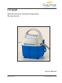
1
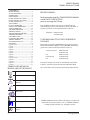
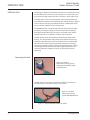
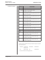
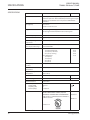
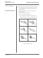
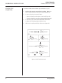
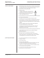
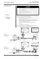
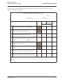
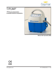
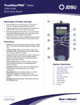
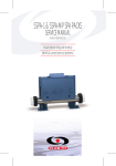
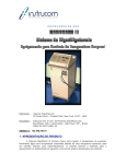
T/PUMP®
TP600 & 700 Series Localized Temperature
Therapy System
Service Manual
www.gaymar.com
P/N 100987000 Rev A 12/08
SERVICE MANUAL
TP600 & 700 Series T/PUMP
CONTENTS
BEFORE YOU BEGIN . . ..........................................2
SAFETY PRECAUTIONS........................................3
INTRODUCTION.....................................................4
PUMP FEATURES....................................................6
KEYPAD FEATURES TP600 SERIES.....................7
KEYPAD FEATURES TP700 SERIES.....................8
KEYPAD FEATURES TP702..................................9
SPECIFICATIONS..................................................10
CLIK-TITE® CONNECTORS.................................. 11
COLDER®-STYLE CONNECTORS...................... 12
START-UP PROCEDURE..................................... 13
SHUTDOWN PROCEDURE................................ 13
STORAGE/CLEANING.........................................14
WATER TEMPERATURE CONTROL.................. 16
THEORY OF OPERATION................................... 17
FUNCTIONAL CHECK......................................... 18
DISASSEMBLY/REASSEMBLY...........................24
TROUBLE SHOOTING......................................... 26
REPLACEMENT PARTS LIST..............................32
WARRANTIES........................................................ 33
Figure 1.a & 1b.......................................................4
Figure 2....................................................................6
Figure 3....................................................................7
Figure 4....................................................................8
Figure 5....................................................................9
Figure 6..................................................................11
Figure 7..................................................................12
Figure 8..................................................................17
Figure 9.a & 9b....................................................18
Figure 10...............................................................21
Figure 11...............................................................29
Figure 12...............................................................30
Figure 13...............................................................31
SYMBOLS USED WITHIN THIS
MANUAL AND ON THE PRODUCT
BEFORE YOU BEGIN . . .
Read and understand this T/PUMP SERVICE MANUAL
and all SAFETY PRECAUTIONS
prior to servicing the T/Pump.
Only qualified medical service personnel should repair or
perform function tests on the T/Pump. Contact your dealer or
Gaymar's Technical Service Department for assistance:
Telephone: (800) 828-7341
(716) 662-2551
TO RETURN PUMPS TO FACTORY FOR REPAIR OR
EXCHANGE
Merchandise returned to GAYMAR must be accompanied by a
Return Goods Number (RG#), issued by GAYMAR, authorizing
goods to be returned. Contact Customer Service at:
Customer Service:
Fax:
International:
Fax:
(800) 828-7341
(716) 662-2551
(800) 993-7890
(716) 662-8757
(716) 662-0730
Provide the model, serial number, and detailed nature of the
problem. You will be given a Return Goods Number (RG#).
The serial number can be found on the bottom of the T/Pump.
Warm Water Fill Line
Cold Water Fill Line
Attention, consult Operator's
Manual.
Water Levels
Water Flow
Dangerous Voltage
Type BF Applied Part
T/PUMP, T/PAD, Mul•T•Pad, Clik-Tite, and Gaymar are registered
trademarks of Gaymar Industries, Inc. U. S. PATENT 4,068,870
© 2008. Gaymar Industries, Inc. All rights reserved.
Do not penetrate with sharp
object.
2
www.gaymar.com
SERVICE MANUAL
TP600 & 700 Series T/PUMP
SAFETY
PRECAUTIONS
SAFETY PRECAUTIONS
• Risk of explosion. Do not use in the presence of flammable
anesthetics.
• Risk of electric shock. Disconnect power before servicing the
T/Pump.
• This device pumps temperature controlled water through a
pad. Set the pad temperature only as directed by and under the
guidance of the prescriber.
• Check the skin integrity of the body surface to which therapy is
applied. Evaluate patient response to temperature application.
• Check patient's skin for adverse reactions every 30 minutes or as
directed by the prescriber.
• Failure to adhere to these warnings could result in patient injury.
• The following Groups/Conditions require additional surveillance:
Group/Condition at risk
Potential Injury
Pediatric patients: The portion of an Hyperthermia/
infant’s skin surface in contact with
Hypothermia
a pad, in relationship to their body
mass, can potentially affect their body
temperature.
Patients with impaired circulation
Ischemia
Areas of application under pressure
Ischemia
• Only qualified medical service personnel should repair the
T/Pump. Improper repair may result in death or serious injury,
equipment damage, or malfunction.
• Use T/Pump TP600 & TP700 series controls with Mul•T•Pads. For
catalog numbers and descriptions, see page 5.
• Do not place additional heat sources between the patient and pad.
Skin damage may result.
• Federal law restricts this device to sale by or on the order of a
physician.
• Do not cover the control unit with blankets, pillows or other
insulating materials. Air flow is required to maintain system
performance.
www.gaymar.com
3
INTRODUCTION
INTRODUCTION
SERVICE MANUAL
TP600 & 700 Series T/PUMP
Heat therapy is effective in the dilation of blood vessels, thereby increasing
the blood flow to the heated area. Heat therapy has a variety of uses, the
most common being treatment of aches and pains in joints and muscles.
Cooling therapy assists in vasoconstriction, decreasing blood flow and
decreasing the metabolism in the affected area. Cooling therapy is applied
in the acute phase of injury minimizing blood loss, inflammation of the
tissue, and can be effective in pain management.
The GAYMAR T/Pump® Localized Temperature Therapy System provides
therapy by warming or cooling the enclosed water, and circulating it
through the Gaymar Mul•T•Pad. The pad is connected to the Gaymar
T/Pump with easy‑to‑use Clik•Tite® or Colder®-style connectors.
The Mul•T•Pad provides the interface for delivering the temperature
therapy. The unique button design allows water to flow and provides
trouble-free operation when the pad is folded to form a customized fit.
This reduces the number of pads your facility must keep in inventory.
The pads are applied to the part of the body requiring therapy, and the
circulating water maintains the pad at the setpoint temperature. The
setpoint temperature (TP700 series only) can be locked to prevent
tampering.
Connecting the Pads
Figure 1a: Localized
Temperature Therapy System
with Single Pad with the TP650
and TP700 Series.
The Mul•T•Pads can be interconnected using Clik-Tite® connectors to
provide therapy to more than one body site at a time.
Figure 1b: Localized
Temperature Therapy
System with Multiple Pads.
Figure 1: Single Pad, Multiple Pad Connections
4
www.gaymar.com
SERVICE MANUAL
TP600 & 700 Series T/PUMP
Catalog Descriptions
INTRODUCTION
Catalog #
TP650
Product Name
Classic Control Unit
TP700/TP702 Professional Control Unit
TP22B * Mul•T•Pad: 15"w x 22"l (38cm x 56cm)
All Polymer. 10 per carton
TP22C * Mul•T•Pad: 15"w x 22"l (38cm x 56cm)
Nonwoven fabric on one side, pliable polymer on the
other side. 1 per carton
TP3E* Mul•T•Pad: 3"w x 23"l (8cm x 58cm)
Nonwoven fabric on one side, pliable polymer on the
other side. 10 per carton
TP12E Mul•T•Pad: 13"w x 18"l (33cm x 46cm)
Nonwoven fabric on one side, pliable polymer on the
other side. 20 per carton
TP22E Mul•T•Pad: 15"w x 22"l (38cm x 56cm)
Nonwoven fabric on one side, pliable polymer on the
other side. 20 per carton
TP26E Mul•T•Pad: 18"w x 26"l (46cm x 66cm)
Nonwoven fabric on one side, pliable polymer on the
other side. 10 per carton
TP22G Mul•T•Pad: 15"w x 22"l (38cm x 56cm)
Heavy Polymer, Reuseable. 10 per carton
TP650C
Classic Control Unit with Colder®-style connectors
TP700C
Professional Control Unit with Colder®-style connectors
TP612E Mul•T•Pad: 13"w x 18"l (33cm x 46cm)
Nonwoven fabric on each side with Colder®-style
connectors. 10 per carton
TP622E Mul•T•Pad: 15"w x 22"l (38cm x 56cm)
Nonwoven fabric on each side with Colder®-style
Connectors. 10 per carton
TP626E Mul•T•Pad: 18"w x 26"l (33cm x 46cm)
Nonwoven fabric on each side with Colder®-style
Connector. 10 per carton
* Non-CE Products
To order any of these products contact your dealer or Gaymar's Customer
Service Department at:
Telephone: 716-662-2551
Fax:
International:
716-662-8757
Fax:
716-662-0730
800-828-7341
800-993-7890
Or, visit our website at www.gaymar.com
www.gaymar.com
5
SERVICE MANUAL
TP600 & 700 Series T/PUMP
FEATURES
PUMP FEATURES
Easy to Use
Keypad
See Keypad Features TP600 series, TP700 series
and TP702.
Attached hose
10 ft (305 cm) dual hose. Connectors allow pads to
be connected to the pump (Figures 1A and 1B).
Flow indicator
Indicates no flow. Turns off heater if pump is tipped.
Warm/Cool
Delivery
Three setpoints on the TP600 series.
Four temperature setpoints on the TP700 series.
Therapy Cycles
(TP700 series
only)
Choose from 20-minute, 30-minute, or Continuous
cycles.
On/Standby
Button
Indicates power is supplied to the unit.
Over Temp
Safety
Thermostat
Limit thermostat shuts off pump and heater if the
high temperature limit is exceeded.
Self Check
Automatic system check at startup.
Hose/cord
Management
Convenient and easy storage areas for hose and
cord.
Comfortable
Handle Design
Designed for a more comfortable grip when moving
the pump.
Dual Micro
Processor
Two electronic circuits, one over temperature
sensing circuit.
Tethered EasyOpen Cap
Prevents misplacing the cap. Only 1/4 of a turn is
needed to remove or secure the cap.
Handle Vents
The vents in the handle allow air flow to keep the
motor and heater inside the unit cool.
Easy to Use Keypad On/Standby Button
Handle Vents
Comfortable Handle
Flow Indicator
Tethered Easy-Open Cap
Cord storage
Temperature
Setpoints for warm
Therapy Time Cycles
(TP700 series only)
Hose storage
Hose Connections
Figure 2: T/Pump Features
6
www.gaymar.com
SERVICE MANUAL
TP600 & 700 Series T/PUMP
FEATURES
KEYPAD FEATURES
TP600 SERIES
Figure 3: TP600 Series Keypad
Indicator/
Warning
Light
See the Troubleshooting section.
Water Flow
Check hoses and clamps for kinks or occlusions.
Water Level
Check water level.
www.gaymar.com
Setpoints
Press the button at the bottom of the setpoint indicator
to toggle through the three setpoints.
High Heat is 107°F (42°C).
Low Heat is 100°F (38°C).
Cooling is 50°F (10°C).
On/Standby
Button
Green indicates the unit is on.
Yellow indicates power is supplied to the unit but the
unit is not on.
7
SERVICE MANUAL
TP600 & 700 Series T/PUMP
FEATURES
KEYPAD FEATURES
TP700 SERIES
Figure 4: TP700 Series Keypad
Indicator/
Warning
Light
See the Troubleshooting section.
Water Flow
Check hoses or clamps for kinks or occlusions.
Water Level
Check water level.
8
Setpoints
Press the button at the bottom of the setpoint indicator
to toggle through the four setpoints. Temperatures are
identified in °C and °F.
Setpoint
Lock
Prevents tampering.
Press and hold for 2 seconds to lock or unlock the
setpoint.
Therapy
Cycles
Continuous cycle, 30-minute cycle or 20-minute cycle.
On/Standby
Button
Green indicates the unit is on.
Yellow indicates power is supplied to the unit but the
unit is not on.
www.gaymar.com
SERVICE MANUAL
TP600 & 700 Series T/PUMP
FEATURES
KEYPAD FEATURES
TP702
!
T/Pump
®
C
42
38
35
10
F
Professional
107
100
95
50
30
20
Figure 5: TP702 Keypad
Indicator/
Warning Light
Control Panel
See the Troubleshooting section.
T/Pump Professional CE
100269
Water Flow
Check hoses or clamps for kinks or occlusions.
Water Level
Check water level.
Setpoints
Press the button at the bottom of the setpoint
indicator to toggle through the four setpoints.
Temperatures are identified in °C and °F.
Setpoint Lock
Prevents tampering.
Press and hold for 2 seconds to lock or unlock the
setpoint.
Therapy
Cycles
Continuous cycle,
30-minute cycle
20-minute cycle.
Green indicates the unit is on.
Yellow indicates power is supplied to the unit but the
unit is not on.
www.gaymar.com
9
SERVICE MANUAL
TP600 & 700 Series T/PUMP
SPECIFICATIONS
SPECIFICATIONS
120V Models
230V Models
Electrical Classification
Class I equipment with Type BF applied part suitable for
continuous operation. Not classified for protection against ingress
of liquid. Not classified for use in the presence of flammable
anesthetics.
Size (approx.)
11.5” x 8” x 8”
29.2cm x 20.3cm x 20.3cm
Weight
6.5 lbs (2.9 kg) when empty
9 lbs (4.0 kg) with unit filled with water to heating level
Reservoir capacity
93 oz (2.75 l) maximum
Flow rate
9 gph (34 lph) minimum with pad attached
Ambient operating
temperature
60°F to 90°F (15.6°C to 32.2°C )
Environmental conditions
for transport and storage
-20°F to 120°F (-28°C to 48°C )
At uncontrolled RH
Temperature setpoints
TP650 Classic
107°F (42°C) High heat
100°F (38°C) - Low heat
50°F (10°C) - Cooling
TP700 Professional
107°F (42°C)
100°F (38°C)
95°F (35°C)
50°F (10°C)
TP702
42ºC
38ºC
35ºC
10ºC
Average temperature
accuracy
±2°F at 107°F (±1°C at 42°C)
Maximum Contact Surface
Temperature
107°F (42°C)
High Limit Safety
Temperature
111°F to 118°F
(44°C to 48°C)
Power cord
International (harmonized) 3-wire cordset
Modular
Current leakage
300 microamperes maximum
500µA Max
Ground resistance
0.5 ohm max
Electrical requirements
Voltage (VAC)
Frequency (Hz)
Current (amps)
120±10%
60
3.1 amperes
Certifications
230+ 10%
50 Hz
1.6 A
MEDICAL ELECTRICAL EQUIPMENT WITH
EN 60601-1-2
RESPECT TO ELECTRICAL SHOCK, FIRE, AND
MECHANICAL HAZARDS ONLY IN ACCORDANCE
IEC 60601-1
WITH UL 60601-1, AND CAN/CSA C22.2 NO 601.1,
ASTM F 2196-2002
EN 60601-1
EN 60601-1-2
10
www.gaymar.com
SERVICE MANUAL
TP600 & 700 Series T/PUMP
CLIK-TITE® CONNECTORS
OPERATING INSTRUCTIONS
The TP600 & 700 Series T/Pump is supplied with Clik-Tite® connectors.
To connect and disconnect Clik-Tite® connectors from hose to pad:
Note: Refer to Figure 1B on page 4
when connecting multiple pads.
1. Insert male fittings into female fittings with a twisting motion
(Figures 6A and 6B).
2. When fittings are fully inserted, snap locking ring into place
(Figures 6C and 6D).
3. To disconnect, reverse the procedure.
4. To open or close the hose pinch clamps:
• Open the clamp by pushing the serrated end (Figure 7B).
• Close the clamp by pressing the clamp together (Figure 7C).
6A
6B
6C
6D
7B
7C
Figure 6: Clik-Tite® Connectors
www.gaymar.com
11
SERVICE MANUAL
TP600 & 700 Series T/PUMP
OPERATING INSTRUCTIONS
COLDER®-STYLE
CONNECTORS
To connect and disconnect Colder®-style connectors to a pad:
1. Push the male coupling onto the female coupling. When you
hear an audible click, the connectors are joined (Figure 7A).
2. To open or close the hose pinch clamps:
• Open the clamp by pushing the serrated end (Figure 7B).
• Close the clamp by pressing the clamp together (Figure 7C)
3. To disconnect, press down on the thumb tab of the female
coupling. The couplings will partially disconnect.
4. Pull the male coupling out fully to disconnect (Figure 7D).
7A
7B
7C
7D
Figure 7: Colder®-Style Connectors
12
www.gaymar.com
SERVICE MANUAL
TP600 & 700 Series T/PUMP
START-UP PROCEDURE
OPERATING INSTRUCTIONS
1. Before filling the pump, always attach a pad to the connector hose or
close the clamps on the connector hose ends. Make sure that there
are no kinks in the hose or pad. Open the hose clamps.
2. Open the fill cap on top of the pump.
3. To fill for cooling:
a. Fill with cold water to the Cooling water line.
b. Fill with ice to the full capacity of the reservoir.
4. To fill for heating, fill with room temperature
water to the Heating water line.
5. Plug the T/Pump into a properly grounded Hospital Grade receptacle.
6. Press the On/Standby button.
The light next to the selected temperature begins to flash.
7. Use the keypad to set the temperature as directed by the prescriber.
For the TP700 Series only, after setting the temperature, press and
hold the lock Temperature Setpoint button for 2 seconds to lock the
setpoint.
Note: If you toggle past the desired setpoint, keep toggling to
start at the beginning of the setpoint column.
If warming, the selected water temperature will be reached in
approximately 11 minutes and the light next to the selected
temperature becomes steady.
8. Check the water level. If it drops below the operating level, add water.
9. Apply the Mul•T•Pad to the patient as prescribed. Follow the
Mul•T•Pad instructions.
10. Position the pump at or above the level of the pad.
Note: If the pump is placed below the pad(s), water will drain
into the pump when it is shut off. If the pump has been overfilled
or if multiple pads are connected, excess water can leak.
SHUTDOWN PROCEDURE
1. Press the On/Standby button so that the Standby light is lit.
2. Unplug the T/Pump.
3. Close all hose clamps.
4. Disconnect pad(s) from pump.
To prevent water spillage, always disconnect pad from pump with
connectors raised above the level of the pad and pump.
5. Coil the hose, and attach the Clik-Tite® connectors together on the
hose (See Figure 5), where applicable.
6. Secure the hose to the T/Pump using the tube set strap.
7. Wrap the power cord around the unit.
www.gaymar.com
13
SERVICE MANUAL
TP600 & 700 Series T/PUMP
STORAGE / CLEANING
STORAGE / CLEANING
Storage (Short term)
Less than 1 day
1. Close the hose clamps.
2. Disconnect the pad.
3. Connect ends of the connector hoses together, where applicable.
4. Open the hose clamps.
5. Leave water in the reservoir.
6. Coil and fasten the hose using the tube set strap and wrap the power
cord around the unit.
Storage (Long term)
1. Drain the pump. (See instructions below.)
2. Coil the hose, rather than folding it, to prevent hose kinks.
3. Fasten the hose using the tube set strap and wrap the power cord
around the unit.
Draining
1. Disconnect the T/Pump from AC power.
2. Clamp the hose clamps.
3. Disconnect the pad or hoses from one another, keeping hoses at or
above the level of the T/Pump.
4. Open the hose clamps.
5. Remove the fill cap and invert the T/Pump over a sink.
6. When all fluid has drained from the hoses and reservoir, replace the
fill cap.
7. Connect the hoses together, where applicable.
14
www.gaymar.com
SERVICE MANUAL
TP600 & 700 Series T/PUMP
Institutional
(Hospital) Cleaning
Instructions
STORAGE / CLEANING
Note: Clean and change the water monthly or more often depending on
use.
Clean the outer surfaces of the T/Pump with one of the following:
• A damp cloth and soapy water.
• A spray cleaner such as Fantastik
• A mild abrasive cleanser without bleach.
1. Prepare a germicidal solution according to the manufacturer's
instructions. Use AirKem A-33, available from Ecolabs, Inc., 370
Wabasha, St. Paul, MN 35102 (phone: 1 800 247‑5362), or from
GAYMAR, product catalog MTA33.
2. Drain the pump.
3. Connect hose set together.
4. Fill the reservoir to the Heating water line on the back of the
reservoir.
5. (TP650) Select Low Heat on the keypad.
(TP700 Series) Select the 95°F (35°C) temperature setpoint on the
keypad.
6. Start the T/Pump, and circulate the solution for one hour.
7. Drain the solution and refill the pump with clean water.
NOTE: In a home environment, perform only step 2 and the refill instructions in step 7.
Pads / Accessories
Only use Mul•T•Pads®. The unique button design allows optimal water
flow and provides trouble-free operation when the pad is folded. This
reduces the number of different sizes of pads your facility must keep in
inventory.
The Mul•T•Pads with Clik-Tite® connectors can be interconnected to
provide therapy to more than one body site at a time (Figure 1B,
page 4). Refer to Catalog Descriptions on page 5 for a list of various pads
and ordering information.
www.gaymar.com
15
WATER TEMPERATURE CONTROL
WATER TEMPERATURE
CONTROL:
There are three devices that control the operation of the heater in the
GAYMAR T/Pump:
•
•
•
FLUID SYSTEM:
SERVICE MANUAL
TP600 & 700 Series T/PUMP
The temperature is thermistor controlled (fig 8, item 8). This
temperature is selectable from the operator's keypad (fig 8, item
10). To prevent unauthorized temperature setting changes, a
lockout key is available on the TP700 "Professional" model.
The limit thermostat (fig 8, item 2) is mounted on the brass
manifold block (figure 8, item 6). This thermostat senses water
temperature flowing to the pad and will shut off the heater if the
water temperature exceeds specific limits (120ºF). The purpose
of the limit thermostat is to prevent the pump from providing
water at too high a temperature to the pad.
The control of the selected temperature is performed by a dual
thermistor (fig 8, item 1) Dual Processor design. The Control
Processor reads its thermistor and determines if heat is required.
If heat is required it sends a signal to an Over Temperature
Processor. The Over Temperature Processor reads its thermistor,
and insures the temperature is below the over temperature
value, before it allows the heater (fig 8, item 5) to turn on.
The pump is a sump configuration magnetically coupled to an
impedance protected, shaded pole AC Motor (fig 8, item 3).
The return hose fitting (fig 8, item 7) is machined internally to act as an
orifice. This maintains a back pressure in the pad to make it resistant to
flow restrictions.
16
www.gaymar.com
SERVICE MANUAL
TP600 & 700 Series T/PUMP
THEORY OF OPERATION
10
1
9
2
3
8
7
6
4
5
Item
Description
1
PC Board (Temperature Controller)
2
Manifold Backup Limit Thermostat
3
Pump Motor
4
Tray Assembly
5
Cartridge Heater
6
Brass Manifold Block
7
Return Hose Fitting
8
Temperature Sensor
9
Housing Front Assembly
10
Ribbon to Front Keypad
Figure 8: T/Pump Components
www.gaymar.com
17
SERVICE MANUAL
TP600 & 700 Series T/PUMP
FUNCTIONAL CHECK
FUNCTIONAL CHECK
INTERVAL
REQUIRED
EQUIPMENT
• Only qualified service personnel should perform this Functional
Check. Improperly following the test procedure may result in
equipment damage.
• Do not perform this Functional Check with an empty reservoir.
Damage to the T/Pump may result.
• Read through and understand each step before performing the
test.
To assure optimum performance, dependability and safety, the following
Functional Check should be performed once per year (or as specified in
the facility's preventive maintenance program).
• TFC1 or equivalent (Thermometer with 30º F to 125ºF (-2ºC to 52º)
range with 2ºF (1ºC) accuracy.
• TPT9 is used to measure the temperature and the flow of the
water entering the pad. (To use with Colder style connectors, also
order adapter hose P/N 77926-000.)
• Stop Watch for testing Over-Temperature Safety Circuit
• Mul•T•Pad
• Test Probe, T/Pump P/N:100925000
Note: To order a TFC1, TPT9, Test Probe and Mul•T•Pad, contact your
dealer or Gaymar's Customer Service Department.
NOTE: If the flow meter is
connected in reverse, the flow
meter will indicate no flow.
Reverse the pump connections
so that the male fitting (with
black O ring) is on the supply
side.
T/Pad, size "12" or "22":
Be sure pad is flat and
at same level as pump.
TFC1:
Fill well
with water
before inserting
thermometer.
Figure 9a:
Functional Check
Setup (Clik-Tite)
TPT9:
9 GPH
minimum.
Read at top
of float.
Plug into a properly
grounded outlet.
Fitting and tube closest
to front of T/Pump
Male Clik-Tite connector
(black O ring)
T/Pad, size "12" or "22":
Be sure pad is flat and
at same level as pump.
NOTE: If the flow meter is connected
in reverse, the flow meter will indicate
no flow. Reverse the pump hose
connections to change the direction
of flow.
TFC1:
Fill well
with water
before inserting
thermometer.
Figure 9b:
Functional Check
Setup (Colder)
Plug into a properly
grounded outlet.
18
Fitting and tube closest
to front of T/Pump
TPT9:
9 GPH
minimum.
Read at top
of float.
Adaptor Hose Assembly
www.gaymar.com
SERVICE MANUAL
TP600 & 700 Series T/PUMP
FUNCTIONAL CHECK
Operating
Temperatures, Flow
and Over-Temperature
Safety Circuit Check
This section provides a complete check of all T/Pump functions. Follow
the steps in this section carefully, paying particular attention to each
step, and its expected result. If at any time the expected result can not
be verified, press the On/Standby button to stop the test, then restart
the procedure. If after a second attempt the expected result can not be
verified, press the On/Standby button to stop the test, then unplug the T/
Pump and call your dealer or Gaymar's Technical Service Department for
assistance.
Test Setup
Connect the T/Pump to the TPT9 and Mul•T•Pad as shown in Figure 9a, 9b.
Physical Condition Check
1. Examine the plug and line cord along its entire length for physical
damage, such as cuts or cracked insulation. A damaged line cord
should be replaced rather than repaired. Check the quality of the strain
relief of the line cord.
2.Examine membrane panel for cuts or cracks. If damaged, replace.
3. Visually inspect pump. Check for cracked or damaged plastic parts.
Be sure unit is unplugged. Remove four (4) screws from the handle
area. Remove four (4) screws securing upper housings to tray. Perform
visual inspection of all internal parts. Remove any accumulated dirt
with a vacuum cleaner or compressed air hose.
4. Check connectors for cracks, missing O rings, or other damage.
Replace connectors if necessary.
Flow & Operating
Temperature Test
Note: Stay present for the full duration of the test to observe all readings
and to prevent damage to the T/Pump.
1. Attach a pad to the connector hose (See Figure 9a/9b). Then, unkink
the pad and hose. Open the hose clamps.
2. Open the fill cap on top of the pump.
3. Fill with room temperature water to the Heating water line.
4. Plug the T/Pump into a properly grounded Hospital Grade receptacle.
The T/Pump performs its self test of the lights and audible alarm,
with light pattern and short audible beep.
The T/Pump goes to Standby mode with only the Standby light
on.
5. Press the On/Standby button.
6. Press and hold the Temperature Setpoint button.
7. While still holding the Temperature Setpoint button, press the On/
Standby button. Hold both buttons simultaneously for 3 seconds and
then release.
The T/Pump gives a long audible beep, and the Warning light
flashes.
Note: If at any time the Function
test needs to be stopped, press
the On/Standby button.
The T/Pump goes into Operating Temperature Function Test
mode, and the:
•
•
www.gaymar.com
T/Pump starts pumping with the Standby light on with a flow of
9 GPH minimum.
107°F (42°C) setting is selected.
19
SERVICE MANUAL
TP600 & 700 Series T/PUMP
FUNCTIONAL CHECK
•
•
Continuous light is on (TP700 Series Only).
System disables the Wave feature to maintain a steady 107°F
supply of water to the pad.
The T/Pump controls to 107°F (42°C) at the inlet to the pad for 15
minutes, the duration of the test.
8. After 13 minutes, verify with the TPT9 that the Temperature is at
107°F +/- 2°F (42ºC+/-1°C) and flow is 9 GPH minimum.
Note: If the T/Pump does not reach the temperature and flow,
press the On/Standby button, unplug the unit, check the pad
and hoses for kinks and start over.
9. After 15 minutes, observe that the T/Pump starts the Over
Temperature Safety Circuit Test.
The T/Pump gives a three long beeps with the Warning light on.
This signals the start of the Over Temperature Safety Circuit Test.
Note: If the system does not shut
down in an over temperature
condition in 30 seconds, press the
On/Standby button, then unplug
the T/Pump. Contact your dealer
or Gaymar’s Technical Service
Department for assistance
Telephone: (800) 828-7341
(716) 662-2551
10. Start the stop watch to make sure the Over Temperature condition is
detected in 30 seconds.
WARNING: If this step is not followed, damage to the T/Pump
may result.
• The T/Pump gives a long beep and flash of the Warning light.
• The pump stops. No water will be flowing to the pad.
• The Heater is turned on at 100% power with no flow.
• The 107ºF (42ºC) Setpoint light starts flashing.
• The 20-minute cycle light starts flashing (TP700 Series Only).
• When the T/Pump detects an Over Temperature Condition
(temperature trip point of 115ºF +5ºF [46ºC +2ºC], the T/Pump
gives an audible beep and flashes the Warning light. The system
then cycles and goes into Standby mode with the Warning light
on.
11. When the Warning light turns on, stop the Stop-Watch.
12. Restart the Stop-Watch to make sure the T/Pump cools down to a
point where the thermostat resets and the Warning light turns off in
60 minutes.
Or, to speed up the cool down, go to step 13.
13. To speed up the cool down:
a. Unplug the T/Pump.
b. Refill the reservoir with room temperature tap water.
c. Restart the unit in Cooling mode.
The system starts cooling down in Standby mode. The
thermostat resets within 5 minutes.
The test is completed.
14. Shut down the T/Pump as described on page 13.
20
www.gaymar.com
SERVICE MANUAL
TP600 & 700 Series T/PUMP
BACKUP LIMIT THERMOSTAT TEST
FUNCTION CHECK
This test is used to insure the temperature at the pad stays below a safe
level in an over temperature condition.
Figure 10: Connection of Test Temperature Sensor
Test Procedure:
1. To perform this test you will need to open the tray assembly (Refer
to section DISASSEMBLY/REASSEMBLY) to install the Test probe, as
shown in figure 10.
2. Attach a pad to the connector hose (See Figure 9a/9b). Then unkink
the pad and hose. Open the hose clamps.
3. Open the fill cap on top of the pump.
4. Fill with room temperature water to heating water line.
5. Plug the T/Pump into a properly grounded Hospital Grade receptacle.
The T/Pump performs its self test of the lights and audible alarm,
with light pattern and short audible beep.
6.
7.
8.
9.
10.
www.gaymar.com
The T/Pump goes to Standby mode with only the Standby light
on.
Press the On/Standby button. The T/Pump starts running at
the default Setpoint of 100ºF (38ºC). Note: The Control & Over
Temperature processor are reading the room temperature. This
makes the system "believe" it will always require the heater due to
the temperature the processors read is below the required Setpoint.
This will drive the water flowing through the system to a temperature
that will "trip" the thermostat (in approximately 10 to 15 minutes).
Record the peak temperature read by the thermometer. The
temperature recorded must be between 108ºF (42.2ºC) and 119ºF
(48.3ºC). If the thermostat operates outside its intended range, it
must be replaced. After the thermostat "Trips" the system will cool
down to a temperature that resets the thermostat (in approximately
20 to 25 minutes). This "Trip"/Reset cycle will continue until the unit
is put back into Standby mode.
Press the On/Standby button. The T/Pump goes into Standby mode.
Unplug the T/Pump.
Unplug the Test probe, and plug the Original Temperature Sensor
back in.
Close the unit. (Refer to section DISASSEMBLY/REASSEMBLY).
21
SERVICE MANUAL
TP600 & 700 Series T/PUMP
FUNCTION CHECK
LEAK TEST
• Immediately upon completion of the previous test, tilt unit
towards you so the front is down. Hold for three (3) minutes.
• Return the unit to upright position and carefully check the
reservoir tray joint for leaks. Repeat process turning pump on
back face. If leakage is found, refer to DISASSEMBLY/REASSEMBLY,
Reservoir section.
Risk of electrical shock. Be sure unit is unplugged when
performing the ground resistance test.
GROUND RESISTANCE CHECK
1. Use a ground resistance meter to measure the resistance between
the ground pin on the plug and the brass manifold block (fig 8, item
6). Contact is available through the hole where the hoses connect to
the pump. This value should not be more than 0.5 ohm.
CURRENT LEAKAGE CHECK
It will be convenient to check current leakage at this point since the unit
is full and connected to a pad.
1. Measure the maximum current leakage in all combinations of
heater "ON" or "OFF" and On/Standby "ON" or Standby. Access to
chassis ground for current leakage testing is available through the
hole where the hose connects to the pump. The highest reading
is typically less than 30 microamperes. The maximum allowable
reading is 100 microamperes (200 microamperes for 230 volt model).
Record the highest reading.
2. Disconnect leakage meter setup.
22
www.gaymar.com
SERVICE MANUAL
TP600 & 700 Series T/PUMP
FUNCTIONAL CHECK
Inspection forms vary from hospital to hospital. The following sample form is intended as a guide so that the
important parameters are recorded.
T/Pump Functional Check and Safety Inspection Form
Date:_______________
Model Number:___________________ Serial Number:___________________
Item
Value
Okay
Action
Needed?
Action
Taken
(check one)
1
Inspect physical condition (line cord, plug, housing)
Inspect hose connections and connectors
2
3
4
5
6
7
Measure flow, >9 gph (34 lph)...indicate value
Measure operating temperature @ 107ºF +2ºF...Indicate
average
Backup limit test 108ºF - 119ºF
Leak Test
Measure ground resistance, <0.5 ohm...indicate value
Measure current leakage, <100µA (120 V), <200µA (230 V)
Signature:______________________________________________________________________
www.gaymar.com
23
SERVICE MANUAL
TP600 & 700 Series T/PUMP
DISASSEMBLY/REASSEMBLY
Reservoir:
• Unplug the Unit.
• Drain the Reservoir.
• Remove the nine (9) screws which retain the Reservoir to the Tray
assembly.
• Lift the Tray assembly from the Reservoir and set aside. Note: Be
careful to keep the Upper Housing with the tray. It can be lifted
from the tray, but there are wires connecting the two parts.
Upper Front & Rear Housing:
• Perform the Steps for Reservoir disassembly.
• Remove the four (4) screws from the back of the Upper Housing
handle.
• Remove the Rear Housing to the Tray, or Front Housing.
PC Board:
• Perform the steps for Reservoir and Upper Front &Rear Housing
disassembly.
• Lift the Upper Front Housing from the Tray assembly.
• Remove the Keypad Ribbon cable (Fig. 8, Item 10) from the PC
Board (Fig. 8, item 1).
• Remove the Temperature Sensor (Fig. 8, Item 8) from the PC Board.
• Remove the 6 wires from the PC Board.
• Remove the 3 Screws from the PC Board.
Heater Kit Assembly:
• Perform the Steps for Reservoir and Upper Front & Rear Housing
disassembly.
• Remove the two (2) screws from the Manifold backup limit
thermostat (Fig 8, Item 2).
• Remove the 2 wires from the Cartridge Heater. One goes to the
PC-Board, the other goes to a neutral wiring connector.
• Remove the Temperature Sensor (Fig 8, Item 8) from the Brass
Heater Manifold.
• Cut the Gray Hose connected to the Brass Heater Manifold.
• Remove the two (2) brass fittings on the bottom of the Tray
assembly which hold the brass manifold block to the tray.
• Discard the two (2) o-rings between the brass heater manifold and
the tray assembly.
24
www.gaymar.com
SERVICE MANUAL
TP600 & 700 Series T/PUMP
DISASSEMBLY/REASSEMBLY
Heater Assembly:
•
Perform the Steps for Reservoir and Upper Front & Rear Housing
disassembly.
• Remove the 2 wires from the Cartridge Heater. One goes to the
PC-Board, the other goes to a neutral wiring connector.
Remove the (2) brass fittings on the bottom of the Tray assembly which
holds the brass manifold block to the tray.
To assembly, reverse the disassembly steps. Special attention is required
for the following:
1. Gray hose can be placed in warm water (<50°C) to facilitate
installation on manifold fittings.
2. All o-rings must be seated. The reservoir o-ring is shaped, and shape
must be aligned with the reservoir.
3. All fittings on the manifold should have teflon tape applied to prevent
leaks.
4. Insure wires are cleared from between enclosures and away from
enclosure screws.
5. Insure wires are routed away from the cooling fan blades.
6. For proper screw size and location for reservoir and housing, refer to
parts illustration and replacement parts list.
www.gaymar.com
25
SERVICE MANUAL
TP600 & 700 Series T/PUMP
TROUBLESHOOTING
TROUBLESHOOTING
Problem
Possible Cause
Remedy
T/Pump will not turn on.
The electrical cord is not plugged
into a properly grounded Hospital
Grade receptacle.
Insert the plug fully into the properly
grounded Hospital Grade receptacle.
T/Pump will not pump.
Water level is low or reservoir is
empty.
Refill with room temperature water
to proper level.
Flow indicator light is on.
Water flow to pad or hose is
restricted.
Straighten the hose.
Clamp is closed.
Open the clamp.
Water level is low or reservoir is
empty.
Refill with room temperature water
to proper level.
T/Pump is filled with water that is
too hot.
Refill with room temperature water
to proper level.
A High Heat (107°F / 42°C) or
Cooling Setpoint was selected
(50°F / 10°C).
Indication only: A Setpoint outside
body temperature range is selected.
Loss of power while unit was in a
Therapy mode. (Possible Power
Fail.)
Insert the plug fully into the
receptacle, place the unit into
Standby mode, then unplug the
T/Pump. If power is removed while
unit is in On-Mode, the Power Fail
alarm will beep for approximately 10
minutes.
Unit is running after a 20- or 30minute “Off “therapy cycle period,
has reached the desired Setpoint,
and is now timing the 20- or 30minute On cycle period (TP700
Series only).
Indication only to indicate an “On”
Therapy cycle period is timing.
Warning indicator & Audible
alarm (Flash / Beep).
The unit just went into, or came out
of Lock mode (TP700 Series only).
Safety Circuit Function Test has
started.
Note: This would be followed with
the unit starting, while still in Standby
mode.
See the Functional Check section for
details.
26
Indication only.
Note: This should only be
performed by medical service
personnel.
If this mode was started in error,
press the On/Standby button to
stop the test and go back to Standby
mode with the pump off.
www.gaymar.com
SERVICE MANUAL
TP600 & 700 Series T/PUMP
Problem
TROUBLESHOOTING
Possible Cause
Remedy
T/Pump running with the
Standby light on.
Safety Circuit Function Test has
started.
Note: This would be followed with
the unit starting, while still in Standby
mode.
See the Functional Check section
for details.
Important: This should only be
performed by medical service
personnel.
If this mode was started in error,
press the On/Standby button to
stop the test and go back to Standby
mode with the pump off.
Warning indicator on with unit
in Standby mode.
Unit shut down in an over
temperature condition.
Empty the reservoir and refill with
room temperature water.
Make sure all clamps are open.
Press the On/Standby button.
Verify flow through the pad.
The Warning light will turn off
within 5 minutes.
Safety Circuit Function Test
completed successfully.
Allow the system to cool for 60
minutes or until the Warning light
turns off.
Flow indicator and Standby
indicator are on with
T/Pump not pumping.
Unit detected a Flow warning for
more than 5 minutes, thus goes to
standby.
Reference “Flow indicator light is on”
above.
Correct the problem, and press the
On/Standby to put the unit back
into Run mode.
Temperature Setpoint light
blinking.
Unit is warming up to the selected
setpoint.
Indication only.
Unit is in Cooling mode, for longer
than 40 minutes.
Follow the shutdown procedure.
Drain the water in reservoir to ice
fill level, and refill with ice. Follow
the start-up procedure.
www.gaymar.com
27
SERVICE MANUAL
TP600 & 700 Series T/PUMP
TROUBLESHOOTING
Problem
Possible Cause
Remedy
Both the Temperature and Therapy
Cycle Setpoint lights are blinking
(TP700 Series Only).
Unit is in “Off” Therapy cycle time.
Indication only.
T/Pump will not heat.
Reservoir is empty.
Refill with room temperature water
to proper level.
Flow is blocked.
Reference “Flow indicator light is on”
above.
Therapy Cycle is off.
Wait for therapy cycle on.
Reservoir is empty.
Refill with room temperature water
to proper level.
Flow is blocked.
Reference “Flow indicator light is on”
above.
Ice is depleted.
Drain excess water to Cooling
water line and fill remainder of
reservoir with ice.
Temperature or Therapy Time
buttons do not work (TP700 Series
Only).
The buttons have been locked.
Press and hold the lock button for
two seconds.
Water leaks from hose
connectors.
Damaged O-ring.
Replace Clik–Tite® connector.
Male: P/N: 03887000
Female P./N: 038840000
Snap Clik–Tite® connector shut.
T/Pump will not cool.
Locking ring on Clik–Tite® connector
is not snapped into place (See
Figure 6)
Colder®-style connector not seated
properly.
28
Secure pad connection to pump
(See Colder®-style Connectors)
Replace connectors or pad if
defective.
www.gaymar.com
SERVICE MANUAL
TP600 & 700 Series T/PUMP
TROUBLESHOOTING
Figure 11: Wiring Diagram
www.gaymar.com
29
SERVICE MANUAL
TP600 & 700 Series T/PUMP
PARTS ILLUSTRATION
1K
2K
3K
4K
5K
6K
Figure 12: Parts Illustration for Kits
30
www.gaymar.com
SERVICE MANUAL
TP600 & 700 Series T/PUMP
PARTS ILLUSTRATION
21
41 42
45 46
14 25
33
35
4
43
36
40
51
12
39
3
17
16
26
16
2
28
11
28
1
7
31
5
6
1
37
53
10
12
7
9
52
27
13
29
32
12
30
20
18
Figure 13: Parts Illustration Continued
www.gaymar.com
31
SERVICE MANUAL
TP600 & 700 Series T/PUMP
REPLACEMENT PARTS LIST
Item
PN
Qty
1K
TP650,
100822002
1
TP700,
100822001
Description
KIT: Upper front & Rear Housing.
Includes both Front & Rear plastic
housing, Label, Keypad.
Item
PN
Qty
19
90514003
3
20
90514013
4
1
100898000
TP702
100898001
3K
TP650,
100819000
1
KIT: PC Board/Sensor Assembly - This
assembly comes with a pre-calibrated
sensor and PCB assembly. They are
a "Matched" set. Do not use the old
sensor with the new PC Board or the old
PC Board with the new sensor.
KIT: Upper Rear Housing Assembly.
Includes Rear Plastic Housing with Label.
21
90514020
4
22
90603000
1
Label Ground Identification
23
91275059
1
Screw, Mach, Flat C'Sunk HD,
24
91390000
1
Toroid, Ferrite Ring
25
91454052
2
Screw, Mach, Fillister Head
26
100092000
2
Connector Lever Nut 3 Terminal
TP650,
100818000
1
TP700,
100818001
#8 x 3/4" LG
CR SST 6-32 x 3/8 LG
KIT: Upper Front Housing Assembly.
Includes Front Plastic Housing with
Label.
27
100127000
1
Reservoir
28
100129000
1
Tray Assembly
TP702
100129001
TP702
5K
100818002
29
100130000
1
Impeller/Magnet Assembly
TP650, TP700
30
100132000
1
Impeller Housing Bottom
31
100133000
1
Impeller Housing Top
1
100821001
6K
KIT: Heater Assembly. Includes Brass
Manifold, 2 O-Rings, 4 Fittings.
TP702
32
100134000
1
Pin, Impeller
100821002
33
100139000
1
Housing, Front Assembly
100820000
1
KIT: Reservoir Assembly. Includes
Reservoir, Gasket, Rubber Feet, Label.
35
100142000
1
Housing, Rear Assembly
36
100144000
1
Heater Assembly 120 VAC
1
03394000
1
Fitting, Manifold
2
03791001
2
Strap Hose - Hose
3
04152000
1
Fan
37
100152000
1
O-Ring, Reservoir
4
04939014
1
Thermostat, Sort
39
100261000
1
Motor/Plate Assembly
5
08086000
1
Hose Assembly - Clik Tites
1
Cord, Power Assembly (Gray)
1
Membrane Panel - Professional
Heater Assembly 230 VAC
TP702
100261001
08648000
7
Source
Locally
3
Tape, Teflon, 1/4" Wide
8
Source
Locally
4
Ty-Wrap, Self Locking
9
81002000
1
Tubing, PVC, Panacea 1/4 ID x 3/8
42
100269002
1
Membrane Panel - Classic
OD x 3 1/2" LG
43
100269003
1
Membrane Panel - CE
11
81002000
90018029
Hose Assembly - Colders
TP702
100144001
6
10
1
1
12
90018075
9
13
90018082
4
40
100267000
TP702
10053-EURO
41
100269001
Tubing, PVC,Panacea 1/4 ID x 3/8
44
100275000
1
Cap, Teathered, Rivet Assembly
OD x 6" LG
45
100283000
1
Magnet Driver Assembly
Screw, Machine 4-40 x 1/2" FH
46
100286000
1
Label, Instruction TP600 Classic
Phillips
47
100286001
1
Label, Instruction TP700 Professional
Screw Mach PH CR 8-32 UNC
48
100289000
1
Label, Ratings Classic
2A x 3/8 LG S
49
100289001
1
Label, Ratings Professional
Screw, Machine Pan HD #8-32
50
100289002
1
Label, Ratings Classic W/Colder
51
100289003
1
Label, Ratings Professional W/Colder
x 1 SST
14
90049005
2
LockWasher, Spring #6 SST
15
90076018
1
Bushing, Straight Thru
16
90295019
2
O-Ring
17
90295020
1
O-Ring, Silicone
18
90385000
4
Cup, Suction
(HEYCO #1210)
32
Screw Type "BT" Thread Cutting
#6-32 x 1/4 LG SST
TP700, TP702
100819001
4K
Screw Type "B1" Thread Cutting
Pan HD SST. #6 x 7/8" LG
100822000
TP650, TP700
Screw Type "B1" Thread Cutting
Pan HD SST. #4 x 3/8" LG
TP702
2K
Description
52
100292000
1
Clip, Cord
53
100378000
1
Cap
54
100578000
1
Label, Danger
www.gaymar.com
SERVICE MANUAL
TP600 & 700 Series T/PUMP
WARRANTIES
WARRANTIES
GAYMAR equipment and products are warranted against defects in
material and workmanship under normal use, and operation from the
date of purchase, for the time periods listed below for the respective
equipment and products. Except for such warranty, GAYMAR disclaims all
other expressed and/or implied warranties including, but not limited to,
the implied warranties of merchantability and of fitness for a particular
purpose.
PUMP
All labor performed and parts provided free of charge for a period of
one (1) full year from the date of purchase, provided the equipment is
returned with prior authorization prepaid to GAYMAR Industries.
PAD, SINGLE PATIENT
USE
Free replacement of product where defects in materials and/or
workmanship are evident at time of delivery, provided the product is
returned with prior authorization prepaid to GAYMAR Industries.
PAD, REUSABLE
Free replacement of product where defects in materials and/or
workmanship occur within 90 days from date of delivery, provided
the product is returned with prior authorization prepaid to GAYMAR
Industries.
PARTS
Defective parts will be exchanged free of charge where defects in
materials and/or workmanship occur within 90 days from date of delivery,
provided the parts are returned with prior authorization prepaid to
GAYMAR Industries.
www.gaymar.com
33
SERVICE MANUAL
TP600 & 700 Series T/PUMP
GAYMAR INDUSTRIES, INC.
10 Centre Drive
Orchard Park, NY
14127-2295
Phone:
1 800 828-7341
(716) 662-2551
International:
(716) 662-8757
Fax:
1 800 993-7890
(716) 662-0748
International:
(716) 662--0730
Available in Canada through:
Waterloo Bedding Co. LTD.
825 Trillium Drive
Kitchener, ON N2R 1J9
Phone:
1.800.203.4293
519.742.4447
T/PUMPS AND T/PADS
ARE MADE IN THE USA
®
34
®
Fax:
519.742.3699
www.gaymar.com