1
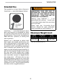
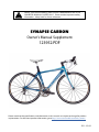
READ THIS SUPPLEMENT AND YOUR CANNONDALE BICYCLE
OWNER’S MANUAL CAREFULLY! Both contain important safety
information. Keep both for future reference.
synapse carbon
Owner’s Manual Supplement
123952.PDF
Please note that the specifications and information in this manual are subject to change for product
improvement. For the latest product information, go to http://www.cannondale.com/tech_center/
EN - 03/09
SAFETY
INFORMATION
WARNING
About This Supplement
Cannondale Owner’s Manual Supplements
provide important model specific safety,
maintenance, and technical information. They
are not replacements for your Cannondale
Bicycle Owner’s Manual.
This supplement may be one of several for
your bike. Be sure to obtain and read all of
them.
If you need a manual or supplement, or have a
question about your bike, please contact your
Cannondale Dealer immediately, or call us at
one of the telephone numbers listed on the
back cover of this manual.
You can download Adobe Acrobat PDF
versions of any Cannondale Owner’s Manuals
or Supplements from our website: http://
www.cannondale.com/bikes/tech.
• This manual is not a comprehensive
safety or service manual for your bike.
• This manual does not include assembly
instructions for your bike.
• All Cannondale bikes must be completely
assembled and inspected for proper
operation by a Cannondale Dealer before
delivery to the owner.
This supplement may include procedures
beyond the scope of general mechanical
aptitude.
Special tools, skills, and knowledge may
be required. Improper mechanical work
increases the risk of an accident. Any
bicycle accident has risk of serious injury,
paralysis or death. To minimize risk
we strongly recommend that owners
always have mechanical work done by an
authorized Cannondale retailer.
WARNING
IMPORTANT COMPOSITES MESSAGE
Your bike is made from composite materials
also known as “carbon fiber.”.
All riders must understand a fundamental
reality of composites. Composite materials
constructed of carbon fibers are strong
and light, but when crashed or overloaded,
carbon fibers do not bend, they break.
For your safety, as you own and use the
bike, you must follow proper service,
maintenance, and inspection of all the
composites (frame, stem, fork, handlebar,
seat post, etc.) Ask your Cannondale Dealer
for help.
We urge you to read PART II, Section D.
“Inspect For Safety” in your Cannondale
Bicycle Owner’s Manual BEFORE you ride.
YOU CAN BE SEVERELY INJURED,
PARALYZED OR KILLED IN AN ACCIDENT
IF YOU IGNORE THIS MESSAGE.
2
123952.PDF
Intended Use
WARNING
The intended use of your bike or frameset is
CONDITION 1 / HIGH PERFORMANCE ROAD.
UNDERSTAND YOUR BIKE AND ITS
INTENDED USE. CHOOSING THE WRONG
BICYCLE FOR YOUR PURPOSE CAN BE
HAZARDOUS. USING YOUR BIKE THE
WRONG WAY IS DANGEROUS.
Industry usage Conditions 1 - 5 are
generalized and evolving. Consult your
Cannondale Dealer about how you intend
to use your bike.
For riding on
pavement
only
CONDITION 1 / HIGH-PERFORMANCE ROAD
bikes and framesets are designed for riding
on a paved surface where the tires do not lose
ground contact. They are not intended to be
ridden off-road, cyclocross, or touring with
racks or panniers.
Material use is optimized to deliver both
light weight and specific performance. You
must understand that (1) these types of bikes
are intended to give an aggressive racer or
competitive cyclist a performance advantage
over a relatively short product life, (2) a less
aggressive rider will enjoy longer frame life, (3)
you are choosing light weight (shorter frame
life) over more frame weight and a longer
frame life, (4) you are choosing light weight
over more dent resistant or rugged frames
that weigh more. All frames that are very
light need frequent inspection for cracks that
would indicate that the frame is worn out from
fatigue. These frames are likely to be damaged
or broken in a crash. They are not designed to
take abuse or be a rugged workhorse.
Please read your Cannondale Bicycle
Owner’s Manual for more information
about Intended Use and Conditions 1-5.
Maximum Weight Limit
RIDER
lbs / kg
LUGGAGE *
lbs / kg
TOTAL
lbs / kg
275 / 125
10 / 4.5
285 / 129
* Seat Bag /Handlebar Bag Only
3
Building Up A Frameset
Bike Stands
The clamping jaws of an ordinary bike stand
can generate a crushing force strong enough
to seriously damage and ruin your bike frame.
Before building up a frameset, consult with
your Cannondale Dealer and the component
manufacturers, and discuss your riding style,
ability, weight, and interest in and patience for
maintenance.
CAUTION
Never place your bike in a bike stand by
clamping the frame.
Make sure the components chosen are
compatible with your bike and intended for
your weight and riding style.
Place your bike in a stand by extending the
seat post and positioning the stand clamp
on the extended seat post. Don’t extend
beyond the MINIMUM INSERT line marked
on the seat post.
Generally speaking, lighter weight components
have shorter lives. In selecting lightweight
components, you are making a trade-off,
favoring the higher performance that comes
with less weight over longevity. If you choose
more lightweight components, you must
inspect them more frequently. If you are a
heavier rider or have a rough, abusive or “go for
it” riding style, buy heavy duty components.
Since your carbon seat post can also be
damaged by clamping force, adjust the
stand clamp for the minimum clamping
force needed to secure the bike.
Read and follow the component manufacturers
warnings and instructions.
Protect From
Extreme Temperatures
• Protect your carbon bike from extreme
temperatures when storing or transporting it.
• Allow your bike to cool off or warm up before
you ride
• Do not store your bike in places where the
temperature will exceed 66.5C° (150°F). For
example, do not leave your bike lying flat in
a black pickup truck bed in the desert sun or
under the glass of a hatchback auto.
4
123952.PDF
Inspection & Crash
Damage of Carbon Frames
WARNING
AFTER A CRASH OR IMPACT:
Inspect frame carefully for damage (See
PART II, Section D. Inspect For Safety in your
Cannondale Bicycle Owner’s Manual.)
Repainting Or Refinishing
You should not paint over the existing finish,
refinish or repaint your bike. The carbon fiber
composites making up the frame are held
together by some extremely strong bonding
chemicals. However, these bonds can be
attacked or weakened by paint stripping or
refinishing chemicals.
WARNING
Do not ride your bike if you see any sign
of damage, such as broken, splintered, or
delaminated carbon fiber.
Repainting, painting over, retouching, or
refinishing your frame or fork can result in
severe damage leading to an accident. You
can be severely injured, paralyzed or killed.
ANY OF THE FOLLOWING MAY INDICATE
A DELAMINATION OR DAMAGE:
Refinishing chemicals : Solvents, and
strippers can attack, weaken, or destroy
the important composite chemical bonds
holding your frame together.
An unusual or strange feel to the frame
Carbon which has a soft feel or altered
shape
Creaking or other unexplained noises,
Using abrasives or sanding the frame/fork
structure, original paint, decals, or coatings
through the use of mechanical actions
such as plastic or glass bead blasting or
other abrasive methods such as sanding
or scraping can remove frame material or
weaken it.
Visible cracks, a white or milky color present
in carbon fiber section
Continuing to ride a damaged frame
increases the chances of frame failure,
with the possibility of injury or death of
the rider.
5
2
1
3
4
serial number
The serial number (1) printed and permanently affixed barcode label. Use this serial number for
warranty registration and theft recovery. See your Cannondale Bicycle Owner’s Manual for more
information on warranty registration.
bottom bracket guide
The cable guide (2) is mounted on the lower bottom bracket. Replacements are available
through a Cannondale Dealer. The kit # is KF363/.
vent
Keep the small vent hole (3) in the bottom of the bottom bracket shell clear of any dirt so that
any water can drain out. Water can enter into frame tubes through washing, condensation, wet
rides, or rain. It penetrates or can be sprayed in through water bottle bosses, seat tube, head
tube and seat post openings. Water will not chemically harm your bike. If it freezes, the ice
expansion can burst or crack the frame making it unsafe to ride. This damage is NOT covered
under your warranty.
After wet rides, remove seat post, invert bike to drain any water.
6
123952.PDF
cable routing
The top tube guide is removable so that brake cable may be routed inside the tube. The
guide is secured in the tube opening by the installed brake cable tension. Make sure the guide
is seated properly in the top tube opening when installing and connecting the rear brake.
Be sure to use ferrules on housing ends. When installing cables, make sure ferrule is seated
inside frame opening correctly.
REAR BRAKE
HOUSING
INTEGRATED GUIDE
BRAKE CABLE
FERRULE
SEAT
REAR BRAKE FRAME OPENING
REAR BRAKE
HOUSING
EXT
ENS
ION
KF
BB G363/
UID
E
FERRULE
KP063/
TOP TUBE GUIDE
SCR
EW
7
seat post
Seat Tube/Binder Preparation
Burrs or sharp edges of the seat tube insert opening can scratch the seat post. Before inserting
the seat post into the frame, do the following:
1. Remove the seat binder exposing the seat tube insert.
2. Lightly round the opening of the insert using 240 grit or lighter sand paper.
3. Apply carbon gel into the opening of the seat tube. Carbon gel has been included in the parts
boxes of 2009 Synapse Carbon. It is also available by ordering Cannondale kit KF115/.
4. To improve clamping force, lightly grease the outside surface of the seat tube insert before
reinstalling the seat binder.
5. Reinstall the seat binder.
6. Before inserting the seat post, apply carbon gel to the seat post.
7. Use a torque wrench to tighten the seat binder bolts to 6 Nm.
SEAT BINDER SHOWN REMOVED
LIGHTLY ROUND OR SMOOTH THE EDGE
OF THE OPENING WITH 240 GRIT OR
LIGHTER SANDPAPER
APPLY CARBON GEL INSIDE THE TUBE.
LIGHTLY GREASE THE SEAT TUBE INSERT
UNDER THE SEAT BINDER
KP095/
6.0 Nm, 53 In Lbs
8
123952.PDF
Saddle Clamp Assembly
1. Apply Loctite® 242 (blue) to the clamp bolt threads.
2. Make sure the seat post head is clean and dry. Do not apply grease.
NOTE: The saddle head is bonded in place. Do not attempt to remove or adjust it.
3. Assembly the parts as shown above.
4. Install the saddle so that the saddle rails locate in the slots between the inner and outer
clamps.
5. Use a torque wrench to tighten the seat saddle clamp 9 - 12 Nm.
DO NOT APPLY GREASE TO
THE SADDLE CLAMP PARTS
SEAT POST HEAD
OUTER
CLAMP
M6X50
CLAMP BOLT
Loctite® 242 (blue)
9 - 12 Nm
INNER
CLAMP
KP096/
INNER
CLAMP
OUTER
THREADED
CLAMP
Loctite® 242
(blue)
WARNING
Saddle rails aligned
with inner and outer clamp grooves.
Incorrect alignment of the saddle clamp
parts can result in the saddle moving
unexpectedly while riding. When adjusting
the saddle angle of your Synapse Carbon,
make sure the saddle rails on both sides of
the saddle are aligned with the inner and
outer clamp on both sides of the saddle.
Ask your Cannondale Dealer for assistance.
SEAT POST
SADDLE
RAILS
YOU CAN BE SEVERELY INJURED, PARALYZED,
OR KILLED IF YOU IGNORE THIS WARNING.
CORRECT
9
Cutting the Seat Post
Depending on the frame size of your Synapse Carbon, the seat post may require cutting to a
shorter length. This must be performed by a professional bike mechanic. The Synapse Carbon
frame has seat post depth in the seat tube that varies with the frame size. Small frame sizes can
accept between 110-130mm. Larger frame sizes can accept between 110-150mm.
To maximize saddle height adjustment range as well as maintain the necessary minimum insert
depth of 80mm of any seat post, the seat post must be fitted (cut) to the frame.
To cut the seat post
1. Insert an uncut post into the seat tube. Insert it until it stops inside the frame. It should slide
in easily. Do not force it into the seat tube. This is the maximum distance inside the seat tube
the post will insert.
2. Determine the maximum desired adjustment range of the saddle that maintains the required
80mm of seat post inside the seat tube.
3. Remove the excess section from the end of the seat post. You should use a cutting guide
such as Park Tool SG-7 and a carbon specific saw blade. See Figure 2. You should also lightly
sand the cut post to round and smooth the cut.
4. Re-mark the MINIMUM INSERT line 80mm up from the bottom of the cut seat post. Mark the
seat post without scoring, scratching or otherwise damaging the surface of the seat post.
Use a thin decal (automotive pin striping) or a paint marker.
NOTE: U.S. Consumer Product Safety Commission (CPSC) bicycle regulations require minimum
seat post insertion be marked on the seat post.
WARNING
If the seat post requires cutting, have it done by a professional bike mechanic with experience
cutting high-performance carbon components.
YOU CAN BE
WARNING.
SEVERELY INJURED, PARALYZED OR KILLED IF YOUR IGNORE THIS
More Information on Carbon Seat Posts
For more information about carbon fiber seat posts, see also “APPENDIX D. Care and Maintenance
of Carbon Fiber Seat Posts” in your Cannondale Bicycle Owner’s Manual.
10
123952.PDF
CUTTING GUIDE
Make a new
permanent
mark here.
SEAT POST
CUT END
Use a 220 or
lighter grit
sandpaper
to round the
cut edge.
(Saddle not shown)
SADDLE
9-12 Nm
80 - 106 In Lbs
HIEGHT
Apply the supplied carbon gel
(Cannondale KF115/) before
installing the seat post.
Tighten bolts uniformly.
SEAT POST
KP095/
6 Nm, 53 In Lbs
SEAT BINDER BOLTS
MINIMUM INSERT
80mm
SEAT TUBE
11
80mm
si bottom bracket
Compatibility
The BB shell is compatible with the BB30 Standard. See http://www.bb30standard.com/ For
information see SI Cranksets Owner’s Manual Supplement. See http://www.cannondale.com/
tech/.
Bearings
Shell bearings are sealed cartridge type and do not require lubrication. Inspect bearing
condition annually (at a minimum) and anytime the crankset assembly is disassembled or
serviced. The bearings are a press fit within the shell. Old bearings should not be reinstalled if
removed. Replace both bearings at the same time.
Replacements circlips (QC616/) are available if the circlips become damaged. The circlips can be
lifted from the BB groove (inset) by lifting the hooked end with a thin blade screwdriver.
CAUTION
DO NOT FACE, MILL OR MACHINE THE BOTTOM BRACKET SHELL FOR ANY REASON.
Doing so can result in serious damage and possibly a ruined bike frame.
SI Tools
KT011/ is a bearing removal tool. KT010/ is a set of bearing installation tools to be used with
a standard headset press. KT013/ a two piece tool set required for removing the crankarms SI
Hollowgram alloy cranksets. For information see SI Cranksets Owner’s Manual Supplement. See
http://www.cannondale.com/tech/.
Cannondale BB30 Standard Bicycle Frames
Certain Cannondale bicycle frames are manufactured using the BB30 standard. See http://
www.BB30standard.com/. It may be possible to convert a BB30 frame for use with standard
English/68mm or 73mm bottom bracket cranksets using the appropriate Cannondale frame
adapter. Other adapters, ones not specifically approved for use by Cannondale may void your
warranty.
WARNING
SERIOUS FRAME DAMAGE CAN OCCUR IF YOU ATTEMPT TO REMOVE A BB30 ADAPTER
FROM A CARBON FIBER FRAME. The bottom bracket shell of certain Cannondale bicycles
are constructed of carbon fiber (composite). If a BB30-to-Standard English adapter has been
installed, IT MUST NOT BE REMOVED.
All Adapters must be installed by a professional bike mechanic. No adapter should be
used as a frame repair part. Adapters should only be used in undamaged frames in good
condition. Improper installation or removal can result in damage and void applicable frame
warranty.
YOU CAN BE SEVERELY INJURED, PARALYZED OR KILLED IN AN ACCIDENT IF YOU
IGNORE THIS WARNING.
12
123952.PDF
QC616/
KB6180/
KP018/ (ceramic)
Park Tool Bearing Cup PressHHP-2
TOOL
Loctite® 609
(green)
groove
TOOL
BB SHELL
ADAPTER
KF365/
13
DRIVE SIDE
Bearing Inspection
1. Remove the crankarms and spindle from
the bottom bracket shell.
2. Rotate the inner bearing race of both
bearings; rotation should be smooth
quietly. No bearing play or movement
inside the shell. If the bearing is
damaged, replace both bearings with
new ones.
Bearing Removal
Frequent or routine renewal of undamaged
bearings is not recommended. Repeated
removal and reinstallation can damage the
inside BB shell surfaces resulting in poor
bearing fit.
1. To remove the bearings, position
Cannondale tool KT011/ behind the
bearing so that the tool ridges are seated
on the bearing.
2. Insert a driver (punch or drift) from the
opposite side. Locate it on the back of
the tool and use light tapping to drive the
bearing from the shell.
14
KT011/
BEARING
123952.PDF
Bearing Installation
1. Clean the inside and outside surfaces of
the bottom bracket shell..
2. Apply a high-quality bicycle bearing
grease to the inside surface of the shell.
CIRCLIPS
3. Install the square end of the circlip into
the groove first, then moving clockwise,
push the clip into the groove until it is fully
seated in the groove. Install the other
circlip the same way.
GROOVE
BB30 SHELL
4. With a headset press, and tool KT010/
install the bearings into the shell as shown.
Press the bearing until it is seated against
the circlip.
5. To finish, apply a light coating of a highquality bicycle bearing grease to both
sides of each bearing to help repel
moisture.
NOTE: Circlip removal is unnecessary for
bearing replacement unless the circlip is
damaged. damage is present. A damaged
circlip can be removed by using a small thinblade screw driver to lift the hooked end up
out of the groove and then pushing the circlip
out counter-clockwise.
KT010/
WARNING
SHARP EDGES. Circlips can have sharp
edges. Wear hand protection.
CAUTION
Do not face, mill or machine the BB30
bottom bracket shell .
Park Tool Bearing Cup PressHHP-2
15
si compression assembly
The cylindrical shape of the TOP CAP fits snugly within the carbon steering tube inside diameter
(I.D.), supporting the steerer from the clamping force of the stem. It must fit snugly inside the
I.D. of the steerer.
How to install the assembly
1. Assemble the fork, headset, spacers, and stem. Make sure that the stem bolts are loose.
2. Set up the compression assembly. “READY TO INSERT” above. The length should be about
48mm as shown above. You can do this by unthreading the top cap from the expander and
then threading it back on about 6-7 turns. The expanding parts should not be expanded.
3. Insert the SI compression assembly into the fork steerer. It should slide in snugly; the TOP
CAP closely fitting the steerer inside diameter.
4. Insert a 5mm Allen key through the access hole in the TOP CAP and into the EXPANDER BOLT.
Tighten the expander by turning clockwise to 6.8Nm, 5 ftLbs.
5. To set bearing preload, insert a 6mm allen key into the hex shape in the TOP CAP iteself.
Turn the entire TOP CAP clockwise to increase preload. Turn counter-clockwise to decrease
preload.
6. When the headset preload is correct, align handlebar and tighten the stem fork clamp bolts
to the torque specified for the stem. Consult the stem since torque values are often marked
on the stem, or consult the manufacturer’s instructions.
WARNING
USE ONLY ORIGINAL EQUIPMENT CANNONDALE SI COMPRESSION ASSEMBLY. Do not
replace it with a star nut or use any other compression or expanding wedge assembly.
DO NOT INSTALL HEADSET SPACERS ON TOP OF THE STEM. Installing spacers above the
stem will raise the TOP CAP inside the steerer removing necessary support for the steerer
tube wall. When stem bolts are tightened. the steerer tube can be damaged.
PLACE HEADSET SPACERS ONLY BETWEEN THE HEADTUBE AND THE BOTTOM OF THE
STEM.
YOU CAN BE SEVERELY INJURED, PARALYZED OR KILLED IF YOUR IGNORE THESE
WARNINGS.
16
123952.PDF
6mm
EXPLODED VIEW
TOP CAP
“READY TO INSERT”
5mm
EXPANDER BOLT
6.8N•m, 5 Ft•Lbs
KP017/
48mm
EXPANDER
Do not grease.
Cut the steerer tube
2 - 3mm below the top
of the installed stem.
CARBON
STEERER
TUBE
HEADSET SPACERS
Thread on TOP CAP.
Set EXPANDER BOLT
so that the the expanding parts
are not expanded and not loose.
STEM
55mm
HEADSET TOP CAP
MAXIMUM STACK HEIGHT
Measure from the top edge of the
headtube to the bottom edge
of the stem.
HEADTUBE
CROWN RACE
(A Headset part KB002/)
BRAKE BOLT
QC778/
17
KF
36
7/
chainstay protection
The chainstay plate ( KF367/ ) located on the right chainstay just behind the chain rings, protects
the chainstay from damage in the event the chain is dropped from the chain ring. Contact your
Cannondale Dealer for a replacement if it is becomes missing or damaged. The clear chainstay
protector (above right) provides limited protection against frame or finish damage caused by
the chain. Replacement protectors are available through a Cannondale Dealer.
rear derailleur
hanger
1.1 Nm
Loctite® 242 (blue)
Before re- installing (same or new): Clean
dropout and inspect carefully for any cracks or
damage. Clean surfaces and apply a light film
of bike grease to the dropout to minimize any
noise or “creaking” that might result from very
slight movement between the dropout and
hanger during movement of the derailleur.
Apply grease and Loctite® carefully. Do not
contaminate the male or female bolt threads
with grease which would cause the Loctite®
to be ineffective.
Check derailleur adjustment after
replacement. Readjust wheel quick release
so it is very tight. See PART I Section 4. A in
your Cannondale Bicycle Owner’s Manual.
LIGHT
GREASE
2.5 mm
KF096/
CAUTION
DO NOT USE A DERAILLEUR HANGER
ALIGNMENT TOOL TO STRAIGHTEN.
18
123952.PDF
TT LENGTH HORIZ
ST LENGTH
HT LENGTH
ST CLAMP
13.0 mm
BB DROP
RAKE 45.0
FRONT CENTER
410.0 CS LENGTH
337.0
337.0
HT ANGLE
ST ANGLE
WHEELBASE
geometry and specification
SIZE
(cm)
ST LENGTH
(cm)
TT LENGTH HORIZ
(cm)
HT ANGLE
ST ANGLE
BB DROP
(cm)
HT LENGTH
(cm)
48
51
54
56
58
61
Feminine
436
466
496
526
546
576
510
525
540
560
580
600
71°
72°
72°
72.5°
73°
73°
74.5°
74°
74°
73.5°
73°
72.5°
72
72
69
69
67
67
130
145
165
180
200
220
FRONT
CENTER
(cm)
565.8
570.7
587.3
599.1
610.3
624.9
WHEELBASE
(cm)
964.8
969.8
987.4
99.3
1011.1
1025.8
44
396
500
70.5°
76°
72
125
567.5
966.5
48
436
510
71°
74.5°
72
130
565.8
964.8
51
466
525
72°
74°
72
145
570.7
969.8
54
506
535
72.5°
74°
72
160
578
977.1
HEADSET
SEAT POST DIA.
SEAT BINDER
DROPOUT SPACING
FRONT DERAILLEUR TYPE
BOTTOM BRACKET
Campy style bearings:
41.8mm OD w/ 45° chamfers
Synapse Carbon specific
BINDER CLAMP MAX TORQUE: 6 Nm
SADDLE CLAMP TORQUE: 9-12 Nm
FRONT
100mm
REAR
130mm
BRAZE ON
BB30
68mm English (w/ adapter)
19
MAXIMUM WEIGHT LIMIT
RIDER
LUGGAGE
TOTAL
275 lbs /
125 kg
10 lbs / 4.5 kg
285 lbs /
129 kg
* Seat Bag /Handlebar Bag Only
INTENDED USE
CONDITION 1
replacement parts
ORDER
KF363/
KF055/
KF367/
KF115/
KF096/
KP063/
FRAME
BB CABLE GUIDE w/fixing bolt
INLINE ADJUSTER (QTY 2)
CHAINSTAY PLATE
SEAT POST GEL
REAR DERAILLUER HANGER
BRAKE GUIDE SLICE AERO
SEATPOST
KP095/
KP096/
SEATBINDER
5 mm Setback
SEAT POST SADDLE CLAMP
25 mm Setback
KP097/5MM
WHT: 9RCL00, 9RCL1 48-51 WHT
KP097/25MM
KP098/5MM
BLK: 9RCL00, 9RCL1 48-51 BLK
KP098/25MM
BLK: 9RCL00, 9RCL1 54-61 BLK
KP099/5MM
WHT: 9RWL00 44-51 WHT
KP099/25MM
FEMININE WHT: 9RWL00 54 WHT
WHT: 9RCL00, 9RCL1 54-61 WHT
KP100/5MM
FEM BLK: 9RWL1 44-51 BLK
KP100/25MM
FEMININE BLK: 9RWL1 54 BLK
KP101/5MM
WHT: 9RCS AND 9RWC 3,4,5,6 44-51 ALL COLORS
KP101/25MM
WHT: 9RCS AND 9RWC 3,4,5,6 54-61 ALL COLORS
KP102/5MM
WHT-SHORT: TEST RIDE 150MM LENGTH
KP102/25MM
WHT-SHORT: TEST RIDE 150MM LENGTH
ORDER
KB002/
QC778/
KP017/
ORDER
QC616/
KB6810/
KP018/
QC615/
KP023/
QC612/
QC617/
QC618/
KT010/
KT011/
KT012/
KT013/
KF365/
QC787/
KP009/
HEADSET & FORK PARTS
KIT,HEADSET,SI CRB W/15 TC
BRAKE BOLT(35mm)
SI COMPRESSION ASSY 23.6ID
SI BB30
SI CIRCLIPS (QTY 2)
SI BEARINGS (QTY 2)
SI CERAMIC BEARINGS (QTY 2)
SI BEARING SHIELD (QTY 2)
SI BEARING SHIELD SL (QTY 2)
SPINDLE-SI ROAD
SI SHIMS (QTY 5)
SI WAVE WASHER
SI BEARING PRESS TOOL(USED WITH HEADSET PRESS)
SI BEARING REMOVAL TOOL
SI LOCKRING TOOL
SI HOLLOWGRAM CRANKARM EXTRACTION TOOL
SIBB/68 ADP.INSTALL
EXTRACT CAP TOOL FOR SI CARBON CRANKSETS
ADAPTER,SIBB TO 68MM TAP
For an up to date list of kits available for your bike, please visit our Tech Center at : http://www.cannondale.
com/bikes/tech/
20