1
www.WorkshopManuals.co.uk www.maskinisten.net Operator Handbook JCB Service World Parts Centre Waterloo Park Uttoxeter England ST14 5PA tel: +44 (0) 1889 - 590312 WWW.JCB.COM 2CX, BACKHOE LOADER MACHINES From Serial Number 930000 ! THIS HANDBOOK MUST BE KEPT IN THE MACHINE AT ALL TIMES ! Publication Number 9801/8800 Purchased from www.WorkshopManuals.co.uk Jan 02 Issue 1 www.WorkshopManuals.co.uk Purchased from www.WorkshopManuals.co.uk www.maskinisten.net www.WorkshopManuals.co.uk SAFETY NOTICES ! WARNING Study This Handbook Before Starting The Machine You must understand and follow the instructions in this handbook. You must observe all relevant laws and regulations. If you are unsure about anything, ask your JCB distributor or employer. Do not guess, you or others could be killed or seriously injured. INT-1-1-1 ! CAUTION Do not fit an attachment to this machine which is not JCB approved. Consult your JCB distributor before fitting any non approved attachment. 8-4-1-6 In this handbook and on the machine there are safety notices. Each notice starts with a signal word. The meanings of the signal words are given below. !DANGER Denotes an extreme hazard exists. If proper precautions are not taken, it is highly probable that the operator (or others) could be killed or seriously injured. INT-1-2-1 !WARNING Denotes a hazard exists. If proper precautions are not taken, the operator (or others) could be killed or seriously injured. INT-1-2-2 !CAUTION Denotes a reminder of safety practices. Failure to follow these safety practices could result in injury to the operator (or others) and possible damage to the machine. INT-1-2-3 MACHINE SECURITY Vandalism and theft of unattended machines is an ever increasing problem and JCB is doing everything possible to help combat this. JCB PLANTGUARD is a comprehensive package available to help you safeguard your machine. It includes such devices as vandal proof covers, window etching, immobiliser, concealed serial number, battery isolator, Tracker security system and much more. Remember that the fitting of any one of these security devices will help to minimise not only the damage or loss of your machine but also subsequent lost productivity. It could also result in reduced insurance premiums. Your JCB Distributor or Dealer will be pleased to provide information on any of these sensible precautions. ACT NOW! INT-1-2-4 8800 - 1 Purchased from www.WorkshopManuals.co.uk www.maskinisten.net www.WorkshopManuals.co.uk CONTENTS i www.maskinisten.net i Page Page INTRODUCTION Loader controls ................................................. Standard shovel ................................................. Float, return to dig .............................................. 6-in-1 clamshovel ............................................... Auxiliary spool .................................................... 38 - 41 39 40 41 41 Stabiliser controls ............................................. 42 Backhoe controls .............................................. JCB X pattern ...................................................... JCB + pattern ...................................................... ISO pattern .......................................................... Hydraclamps ...................................................... Backhoe attachment control (if fitted) ................. 43 - 52 43 - 45 46 - 48 49 - 51 52 52 Before starting the engine ............................... 53 7 Starting the engine ........................................... 54 8-9 8 8 8 9 Jump-starting the engine ................................ 55 Preparing the machine for travel ..................... Road travelling position....................................... Site travelling position ........................................ 56 - 59 57 59 Boom and slew locks ........................................ 60 - 61 About this handbook ........................................ Using this handbook ........................................... Units of measurement ......................................... Page numbering .................................................. Left side, right side ............................................. Using the machine .............................................. 1 1 1 1 1 1 The JCB 2CX Backhoe Loader......................... 2 Safety - yours and others ................................. 3 Safety check list ................................................ General safety ..................................................... Operating safety .................................................. Maintenance safety ............................................. 3-6 3 4 5-6 Safety decals ..................................................... Identifying your machine .................................. Machine identification plate ................................ Typical machine identification number................ Typical engine identification number................... Unit Identification ................................................ OPERATION Introduction ....................................................... 21 Testing the parking brake ................................ 62 Before entering the cab ................................... 21 - 22 Getting the machine moving ............................ 63 - 64 Entering/leaving the cab Entering & leaving the cab................................... Loader control lever lock..................................... Stopping and parking the machine ................. 65 23 23 Site safety ......................................................... 66 - 67 Doors and windows .......................................... Opening and closing the door ............................ Opening and closing the front side window........ Opening and closing the rear window................. 24 - 25 24 24 25 Working with the loader.................................... Operating hints .................................................... Filling the loader shovel ...................................... Loading a truck ................................................... Getting the machine unstuck ............................. 68 - 69 68 68 69 69 Radio console .................................................... 25 Working with the backhoe................................ Operating hints .................................................... Preparing to use the backhoe ............................ Removing a bucket ............................................ Fitting a bucket.................................................... Digging ................................................................ Sideshifting the backhoe..................................... Lifting with the backhoe ...................................... Using the extending dipper ................................. 70 - 75 70 70 71 71 72 73 74 75 Operating in high and low temperatures ........ 76 Moving a disabled machine ............................. 77 Transporting the machine ................................ 78 Seat controls Option 1 - ‘Kab’ Type ......................................... Option 2 - ‘Isringhausen’ Type ........................... 26 27 Seat belt ............................................................ Fasten the seat belt ............................................ Release the seat belt .......................................... Check the seat belt is operating correctly .......... 28 28 28 28 Engine and drive controls, switches and instruments ................................ Controls .............................................................. Switches ............................................................. Instruments ......................................................... 29 - 35 30 - 31 32 - 33 34 - 35 Air conditioning and heater controls .............. 36 Fire extinguisher (when fitted) Using the fire extinguisher................................... 37 8800 - 1 Purchased from www.WorkshopManuals.co.uk www.WorkshopManuals.co.uk CONTENTS ii www.maskinisten.net ii Page Page Service requirements ........................................ Introduction ......................................................... Maintenance........................................................ Owner/Operator support ..................................... Service/Maintenance agreements....................... Lifting regulations - inspections and tests .......... 101 101 101 101 101 101 Lubricants - health and safety ......................... 102 Fuel system ........................................................ 125 - 127 Types of fuel ........................................................ 125 Fuel standards..................................................... 125 Low temperature fuels......................................... 125 Petrol ................................................................... 125 Filling the tank ..................................................... 125 Draining the fuel filter .......................................... 126 Changing the filter element ................................. 126 Draining/cleaning the sediment bowl .................. 127 Bleeding the fuel system ..................................... 127 MAINTENANCE Service schedules ............................................. 103 - 105 Loader arm safety strut .................................... Installing .............................................................. Removing ............................................................ 106 106 106 Checking for damage........................................ 107 Cleaning the machine ....................................... 107 Seat belt ............................................................. Checking the seat belt condition and security .... 108 108 Obtaining replacement parts............................ 108 ROPS/FOPS structure....................................... Checking the ROPS/FOPS structure .................. 109 109 Fire extinguisher (when fitted) Checking the fire extinguisher............................. 109 Engine Panels Removing and fitting a side panel ....................... Opening and closing the bonnet ......................... 110 110 Greasing ............................................................ 115 - 117 118 Tyres and wheels .............................................. Tyre inflation ........................................................ Checking the road wheel tightness .................... 119 119 119 Engine air filter................................................... 120 - 121 Cleaning the pre-cleaner ..................................... 120 Changing the elements ...................................... 121 Engine oil and filter............................................ Checking the oil level ......................................... Changing the oil and filter ................................... 128 128 128 Brakes ................................................................ Parking brake adjustment .................................. Checking the foot brake fluid level ..................... 129 129 129 Axles .................................................................. 130 - 131 Checking the differential oil level......................... 130 Changing the differential oil................................. 130 Checking the hub oil levels ................................. 131 Changing the hub oil .......................................... 131 Greasing (daily) .................................................. 111 - 114 Lubrication ......................................................... Syncro shuttle transmission............................. Checking the oil level ......................................... Changing the oil and filter ................................... 122 122 122 Engine cooling system...................................... 123 - 124 Adjusting the fan belt ......................................... 123 Checking the coolant level ................................. 123 Changing the coolant ......................................... 124 Hydraulic system Checking the fluid level ...................................... Changing the filter element ................................. 132 133 Electrical system Fuses .................................................................. Relays ................................................................. Link Box Fuses .................................................... Bulbs .................................................................. 134 134 135 135 Battery Warning Symbols ................................................ First aid - electrolyte ........................................... Checking the electrolyte level ............................ 136 137 137 Cab heater Changing the filter .............................................. 138 Windscreen washer .......................................... 138 Stabiliser legs .................................................... Wear Pads ........................................................... Wear Pad Adjustment ......................................... 139 139 139 Aligning the road wheels ................................. 140 Fluids, lubricants, capacities and specifications Capacities and Lubricants................................... Coolant mixtures ................................................ 141 142 OPTIONAL ATTACHMENTS Introduction ....................................................... Attachments available for your machine ............ 8800 - 1 Purchased from www.WorkshopManuals.co.uk 151 151 www.WorkshopManuals.co.uk CONTENTS iii Page Quick Release Couplings.................................. Quick release couplings - do's & don'ts ............. Connecting quick release couplings ................... Disconnecting quick release couplings............... 152 152 152 152 Excavator Quick Hitch ...................................... 153 - 155 Installing the quick hitch...................................... 153 Removing the quick hitch.................................... 153 Installing excavator quick hitch attachments ...... 154 Removing excavator quick hitch attachments .... 155 SPECIFICATION Lifting (craning) regulations ............................ 181 Safe working loads Backhoe Unit ...................................................... Loader Unit ......................................................... 181 181 Backhoe bucket weights and dimensions General purpose buckets (standard profile) ........ Grading buckets .................................................. 182 182 Weights and dimensions .................................. 183 Tyre sizes and pressures .................................. 184 Noise and Vibration Data .................................. 185 8800 - 1 Purchased from www.WorkshopManuals.co.uk www.maskinisten.net iii www.WorkshopManuals.co.uk INTRODUCTION 1 www.maskinisten.net 1 ABOUT THIS HANDBOOK Page Numbering This handbook provides information for the 2CX Backhoe Loader range of Machines. The page numbering system in this handbook is not continuous. There is a gap of a few pages between sections. This allows for the insertion of new pages in later issues of the handbook. Serial No. 930000 onwards. Using this Handbook Left Side, Right Side The illustrations in this handbook are for guidance only. Where the machines differ, the text and/or the illustration will specify. In this handbook, 'left' A and 'right' B mean your left and right when you are seated correctly in the machine. This is so whether you are facing the loader (front) or the backhoe (rear). This handbook is arranged to give you a good understanding of the machine and its safe operation. It also contains maintenance information and specification data. Read this handbook from front to back before using the machine for the first time. Particular attention must be given to all the safety aspects of operating and maintaining the machine. Using the Machine The 2CX range of machines can do many jobs. If these jobs are to be done well and safely you must know the machine, its controls and its safe operation. It is not a training manual on the art of loading. If you are a new operator, get yourself trained in the skills of using a backhoe loader before trying to work with it. If you don't, you will not do your job well, and you will be a danger to yourself and others. General warnings in this chapter are repeated throughout the book, as well as specific warnings. Read all the safety statements regularly, so you do not forget them. Remember that the best operators are the safest operators. Finally, treat this handbook as part of the machine. Keep it clean and in good condition. Do not operate the machine without a handbook in the cab. If there is anything you are not sure about, ask your JCB distributor or employer. Do not guess, you or others could be killed or seriously injured. The manufacturer's policy is one of continuous improvement. The right to change the specification of the machine without notice is reserved. No responsibility will be accepted for discrepancies which may occur between specifications of the machine and the descriptions contained in this publication. INT-1-2-5/1 Units of Measurement In this handbook, the S.I. system of units is used. For example, liquid capacities are given in litres. The Imperial units follow in parenthesis () - for example 28 litres (6 gal). S137100 8800 - `1 Purchased from www.WorkshopManuals.co.uk www.WorkshopManuals.co.uk INTRODUCTION 2 www.maskinisten.net 2 THE JCB 2CX BACKHOE LOADER Machine Description The backhoe loader is a self propelled wheeled machine with a main structural support designed to carry both a front mounted bucket loading mechanism and a rear mounted backhoe. When used in the backhoe mode, the machine normally digs below ground level with bucket motion towards the machine; the backhoe lifts, swings and discharges material while the machine is stationary. When used in the loader mode, the machine loads or excavates through forward motion of the machine, and lifts, transports and discharges material. ROPS/FOPS CAB FUEL FILLER CAP LOADER ARM SHOVEL BATTERY COVER 393841 DIPPER BOOM STABILISER LEG BUCKET HYDRAULIC TANK SIGHT GLASS 393842 8800 - 1 Purchased from www.WorkshopManuals.co.uk www.WorkshopManuals.co.uk INTRODUCTION 3 www.maskinisten.net 3 SAFETY - YOURS AND OTHERS All construction and agricultural equipment can be hazardous. When a backhoe loader is correctly operated and properly maintained, it is a safe machine to work with. But when it is carelessly operated or poorly maintained it can become a danger to you (the operator) and others. Do not work with the machine until you are sure that you can control it. In this handbook and on the machine you will find warning messages. Read and understand them. They tell you of potential hazards and how to avoid them. If you do not fully understand the warning messages, ask your employer or JCB distributor to explain them. If you are unsure of anything, about the machine or the job, ask someone who knows. Do not assume anything. Do not start any job until you are sure that you and those around you will be safe. Remember BE CAREFUL BE ALERT BE SAFE But safety is not just a matter of responding to the warnings. All the time you are working on or with the machine you must be thinking what hazards there might be and how to avoid them. INT-1-3-1/1 As well as general warnings in this chapter, specific warnings are given throughout the book. Read all safety statements regularly, so you do not forget them. SAFETY CHECK LIST General Safety ! WARNING ! WARNING Handbook You and others can be injured if you operate or maintain the machine without first studying this handbook. Read the safety instructions before operating the machine. If you do not understand anything, ask your employer or JCB distributor to explain it. Keep this handbook clean and in good condition. Do not operate the machine without a handbook in the cab, or if there is anything on the machine you do not understand. Alcohol and Drugs It is extremely dangerous to operate machinery when under the influence of alcohol or drugs. Do not consume alcoholic drinks or take drugs before or whilst operating the machine or attachments. Be aware of medicines which can cause drowsiness. INT-1-3-2 INT-1-3-9 Passengers Passengers in or on the machine can cause accidents. The JCB Backhoe Loader is a one-man machine. Do not carry passengers. ! WARNING Clothing You can be injured if you do not wear the proper clothing. Loose clothing can get caught in the machinery. Wear protective clothing to suit the job. Examples of protective clothing are: a hard hat, safety shoes, safety glasses, a well fitting overall, ear-protectors and industrial gloves. Keep cuffs fastened. Do not wear a necktie or scarf. Keep long hair restrained. INT-1-3-6 ! CAUTION INT-2-2-2 ! WARNING Raised Attachments Raised attachments can fall and injure you. Do not walk or work under raised attachments unless they are safely blocked. INT-1-3-8 ! WARNING ! CAUTION Regulations Obey all laws, work site and local regulations which affect you and your machine. Machine Modifications This machine is manufactured in compliance with legislative and other requirements. It should not be altered in any way which would affect or invalidate any of these requirements. For advice consult your JCB Distributor. INT-1-3-3 ! WARNING Care and Alertness All the time you are working with or on the machine, take care and stay alert. Always be careful. Always be alert for hazards. Reference should also be made to Optional Attachments section where appropriate. INT-1-3-10 INT-1-3-5 8800 - 1 Purchased from www.WorkshopManuals.co.uk www.WorkshopManuals.co.uk INTRODUCTION 4 www.maskinisten.net 4 SAFETY CHECK LIST (continued) Operating Safety ! WARNING ! WARNING Machine Condition A defective machine can injure you or others. Do not operate a machine which is defective or has missing parts. Make sure the maintenance procedures in this handbook are completed before using the machine. Visibility Accidents can be caused by working in poor visibility. Keep windows clean and use your lights to improve visibility. Do not operate the machine if you cannot see properly. INT-2-1-2 INT-2-1-11 ! WARNING ! WARNING Lifting Equipment You can be injured if you use faulty lifting equipment. Make sure that lifting equipment is in good condition. Make sure that lifting tackle complies with all local regulations and is suitable for the job. Make sure that lifting equipment is strong enough for the job. Electrical Circuits Understand the electrical circuit before connecting or disconnecting an electrical component. A wrong connection can cause injury and/or damage. INT-3-1-4 ! WARNING INT-1-3-7 Ramps and Trailers Water, mud, ice, grease and oil on ramps or trailers can cause serious accidents. Make sure ramps and trailers are clean before driving onto them. Use extreme caution when driving onto ramps and trailers. ! WARNING Engine The engine has rotating parts. Do not open the engine cover while the engine is running. Do not use the machine with the cover open. INT-2-2-6 INT-2-1-6 ! WARNING ! WARNING Safety Barriers Unguarded machines in public places can be dangerous. In public places, or where your visibility is reduced, place barriers around the work area to keep people away. Machine Limits Operating the machine beyond its design limits can damage the machine, it can also be dangerous. Do not operate the machine outside its limits. Do not try to upgrade the machine performance with unapproved modifications. INT-2-2-8 ! WARNING INT-2-1-4 Parking An incorrectly parked machine can move without an operator. Follow the instructions in this handbook to park the machine correctly. ! WARNING Controls You and others can be killed or injured if you operate the control levers from outside the cab. Operate the control levers only when you are seated correctly in the cab. INT-2-2-4 ! WARNING INT-2-1-3 Road Wheel Alignment At the start of each working period, and at least once a day, or if having difficulty in steering, check and, if necessary, re-align the road wheels. Hazardous Atmospheres This machine is designed for use in normal out door atmospheric conditions. It should not be used in an enclosed area without adequate ventilation. Do not use the machine in a potentially explosive atmosphere, i.e. combustible vapours, gas or dust, without first consulting your JCB Distributor. 2-1-1-10 INT-2-1-14 ! WARNING ! DANGER Sparks Explosions and fire can be caused by sparks from the exhaust or the electrical system. Do not use the machine in closed areas where there is flammable material, vapour or dust. INT-2-2-10 8800 - 1 Purchased from www.WorkshopManuals.co.uk www.WorkshopManuals.co.uk INTRODUCTION 5 www.maskinisten.net 5 SAFETY CHECK LIST (continued) Maintenance Safety ! WARNING ! WARNING Modifications and Welding Non-approved modifications can cause injury and damage. Parts of the machine are made from cast iron; welds on cast iron can weaken the structure and break. Do not weld cast iron. Contact your JCB dealer before modifying the machine. Battery Terminals The machine is negatively earthed. Always connect the negative pole of the battery to earth. When connecting the battery, connect the earth (-) lead last. INT-3-1-2/1 When disconnecting the battery, disconnect the earth (-) lead first. ! WARNING INT-3-1-9 Metal Splinters You can be injured by flying metal splinters when driving metal pins in or out. Use a soft faced hammer or drift to remove and fit metal pins. Always wear safety glasses. ! WARNING Repairs Do not try to do repairs or any other type of maintenance work you do not understand. Get a Service Manual from your JCB distributor, or get the work done by a specialist engineer. INT-3-1-3 ! WARNING Safety Strut Raised loader arms can drop suddenly and cause serious injury. Before working under raised loader arms, fit the loader arm safety strut. INT-3-1-1 ! WARNING Hydraulic Pressure Hydraulic fluid at system pressure can injure you. Before disconnecting or connecting hydraulic hoses, stop the engine and operate the controls to release pressure trapped in the hoses. Make sure the engine cannot be started while the hoses are open. 2-1-1-6 ! WARNING Communications Bad communications can cause accidents. If two or more people are working on the machine, make sure each is aware of what the others are doing. Before starting the engine make sure the others are clear of the danger areas; examples of danger areas are: the rotating blades and belt on the engine, the attachments and linkages, and anywhere beneath or behind the machine. People can be killed or injured if these precautions are not taken. INT-3-1-11/1 ! WARNING Counterweights Your machine may be fitted with counterweights. They are extremely heavy. Do not attempt to remove them. Hydraulic hoses Damaged hoses can cause fatal accidents. Inspect the hoses regularly for: Damaged end fittings Chafed outer covers Ballooned outer covers Kinked or crushed hoses Embedded armouring in outer covers Displaces end fittings. INT-3-2-5 INT- 3-3-2 INT-3-1-5 ! WARNING ! WARNING ! WARNING Fires If your machine is equipped with a fire extinguisher, make sure it is checked regularly. Keep it in the operator's cab until you need to use it. Accumulators The accumulators contain hydraulic oil and gas at high pressure. Prior to any work being carried out on the braking system they must be discharged by a JCB distributor as the sudden release of the hydraulic oil or gas may cause injury. Do not use water to put out a machine fire, you could spread an oil fire or get a shock from an electrical fire. Use carbon dioxide, dry chemical or foam extinguishers. Contact your nearest fire department as quickly as possible. Firefighters should use self-contained breathing apparatus. 7-1-1-4 INT-3-2-7/1 8800 - 1 Purchased from www.WorkshopManuals.co.uk www.WorkshopManuals.co.uk INTRODUCTION 6 www.maskinisten.net 6 SAFETY CHECK LIST (continued) Maintenance Safety (continued) ! WARNING ! WARNING Fluoroelastomeric Materials Certain seals and gaskets (e.g. crankshaft oil seal) on JCB machines contain fluoroelastomeric materials such as Viton, Fluorel and Technoflon. Fluoroelastomeric materials subjected to high temperatures can produce highly corrosive hydrofluoric acid. THIS ACID CAN SEVERELY BURN. Under no circumstances must the engine be run with the transmission in gear and only one driving wheel jacked clear of the ground, since the wheel on the ground will move the machine. INT-3-1-16 New fluoroelastomeric components at ambient temperature require no special safety precautions. Used fluoroelastomeric components whose temperatures have not exceeded 300°C require no special safety precautions. If evidence of decomposition (e.g. charring) is found, refer to the next paragraph for safety instructions DO NOT TOUCH COMPONENT OR SURROUNDING AREA. Used fluoroelastomeric components subjected to temperatures greater than 300°C (e.g. engine fire) must be treated using the following safety procedure. Make sure that heavy duty gloves and special safety glasses are worn: 1 Ensure that components have cooled then remove and place material into plastic bags. 2 Thoroughly wash contaminated area with 10% calcium hydroxide or other suitable alkali solution, if necessary use wire wool to remove burnt remains. 3 Thoroughly wash contaminated area with detergent and water. 4 Contain all removed material, gloves etc. used in this operation in sealed plastic bags and dispose of in accordance with Local Authority Regulations. DO NOT BURN FLUOROELASTOMERIC MATERIALS. If contamination of skin or eyes occurs, wash the affected area with a continuous supply of clean water or with calcium hydroxide solution for 15-60 minutes. Get medical attention immediately. INT-3-3-5/1 8800 - 1 Purchased from www.WorkshopManuals.co.uk www.WorkshopManuals.co.uk INTRODUCTION 7 www.maskinisten.net 7 SAFETY DECALS Decals on the machine warn you of particular hazards. Each decal is attached close to a part of the machine where there is a possible hazard. Read and make sure you understand the safety message before you work with or on that part of the machine. ! WARNING If you need eye-glasses for reading, make sure you wear them when reading the safety decals. Decals are strategically placed around the machine to remind you of possible hazards. Do not over-stretch or place yourself in dangerous positions to read the decals. Keep all decals clean and readable. Replace lost or damaged decals. The decals and their attachment points are shown on the following pages. Each decal has a part number printed on it, use this number to order a new decal from your JCB distributor. INT-3-3-4 ! WARNING Decals You can be injured if you do not obey the decal safety instructions. Keep decals clean. Replace unreadable or missing decals with new ones before operating the machine. Make sure replacement parts include warning decals where necessary. INT-3-3-3 INT-1-3-4 S227220 8800 - 1 Purchased from www.WorkshopManuals.co.uk www.WorkshopManuals.co.uk www.maskinisten.net 8 INTRODUCTION 8 IDENTIFYING YOUR MACHINE Machine Identification Plate Typical Machine Identification Number Your machine has an identification plate X mounted on the loader tower as shown. The serial numbers of the machine and its major units are stamped on the plate. The serial number of each major unit is also stamped on the unit itself. If a major unit is replaced by a new one, the serial number on the identification plate will be wrong. Either stamp the new number of the unit on the identification plate, or simply stamp out the old number. This will prevent the wrong unit number being quoted when replacement parts are ordered. SLP 2CX T S R E 123456 A B C D E F G A World Manufacturer Identification B Machine Model C Steer Type (T= 2WS, F=4WS) The machine and engine serial numbers can help identify exactly the type of equipment you have. D Build Type (S=Sideshift, C=Centremount, L=Loader) E Year of Manufacture: 1 = 2001 2 = 2002 3 = 2003 4 = 20047 5 = 2005 6 = 2006 7 = 2007 8 = 2008 F Manufacturer Location (E = England) G Machine Serial Number Typical Engine Identification Number AB 50262 U 500405 P A B C D E A Engine Type AB = 4 cylinder turbo B Build Number C Country of Origin D Engine Sequence Number E Year of Manufacture X S227230 8800 - 1 Purchased from www.WorkshopManuals.co.uk www.WorkshopManuals.co.uk INTRODUCTION 9 www.maskinisten.net 9 IDENTIFYING YOUR MACHINE Unit Identification The engine serial number is stamped on a label Y which is fastened to the left side of the cylinder block (looking from the rear). The Syncro Shuttle serial number is stamped on a label Z which is mounted to the rear face of the unit. The rear axle serial number is stamped on a plate W mounted to the front face of the axle, just above the propshaft coupling. The front axle serial number is stamped on a plate V mounted to the rear face of the axle. Y W S175510 S181760 V Z S181770 S175520 8800 - 1 Purchased from www.WorkshopManuals.co.uk www.WorkshopManuals.co.uk Purchased from www.WorkshopManuals.co.uk www.maskinisten.net www.WorkshopManuals.co.uk OPERATION 21 www.maskinisten.net 21 INTRODUCTION This chapter is arranged to guide you step-by-step through the task of learning how to use the machine. Read it through from beginning to end. By the end of the chapter you should have a good understanding of the machine and how to operate it. Take great care when practicing with the attachment controls. Practice in an open space. Keep people clear. Do not jerk the controls; operate them slowly until you understand the effect they have on the machine. Finally, do not rush the job of learning. Take your time and take it safely. Pay particular attention to all safety messages. They are there to warn you of possible hazards. Do not just read them; think about what they mean. Understand the hazards and how to avoid them. Remember BE CAREFUL If there is anything you do not understand, ask your JCB distributor. He will be pleased to advise you. BE ALERT BE SAFE When you have learned where the driving controls are and what they do, practice using them. Practice driving the machine in a safe, open space clear of other people. Get to know the 'feel' of the machine and its driving controls. Move on to the attachment controls only when you can drive the machine confidently and safely. BEFORE ENTERING THE CAB c Make sure the cab step and handholds are clean and dry. The following checks should be made each time you return to the machine after leaving it for any period of time. We advise you also to stop the machine occasionally during long work sessions and do the checks again. d Clean all safety decals. Replace any that are missing or cannot be read. All these checks concern the serviceability of the machine. Some concern your safety. Get your service engineer to check and correct any defects. 2 Check for Damage a Inspect the machine generally for damaged and missing parts. ! WARNING Walking or working under raised attachments can be hazardous. You could be crushed by the attachments or get caught in the linkages. b Make sure that the shovel, bucket and their teeth are secure and in good condition. c Make sure that all pivot pins are secured correctly in place. Lower the attachments to the ground before doing these checks. If you are new to this machine, get an experienced operator to lower them for you. d Inspect the windows for cracks and damage. Glass splinters can blind you. If there is nobody to help you, study this handbook until you have learned how to lower the attachments. Also make sure that the parking brake is engaged before doing these checks. e Check for oil, fuel and coolant leakages beneath the machine. 2-2-1-1 1 ! WARNING Check for Cleanliness You could be killed or injured if a machine tyre bursts. Do not use the machine with damaged, incorrectly inflated or excessively worn tyres. a Clean the windows, light lenses and rear view mirrors. 2-2-1-2 b Remove dirt and debris, especially from around the linkages, rams, pivot points and radiator. 8800 - 1 Purchased from www.WorkshopManuals.co.uk www.WorkshopManuals.co.uk OPERATION 22 www.maskinisten.net 22 BEFORE ENTERING THE CAB (continued) 3 Check the Tyres a Make sure the tyres are correctly inflated. See Tyres and Wheels (MAINTENANCE section) for a safe procedure for inflating the tyres. b Check for cut rubber and penetration by sharp objects. Do not use a machine with damaged tyres. 4 B Check the Engine Panels and Fuel/Hydraulic Fluid Filler Caps a Make sure the engine panels are fitted and secure. b Make sure the hydraulic fluid filler cap A and fuel filler cap B are tightly closed. (We also recommend that you lock the filler caps.) 391650 A 391640 8800 - 1 Purchased from www.WorkshopManuals.co.uk www.WorkshopManuals.co.uk OPERATION 23 www.maskinisten.net 23 ENTERING/LEAVING THE CAB Entering & Leaving the Cab Loader Control Lever Lock (if fitted) ! WARNING To prevent the loader arms and the backhoe from being accidentally operated when the driver is entering or leaving the cab, or driving on the highway, safety locking pins X can be installed. Entering and leaving the cab or canopy must only be made where steps and handrails are provided. Always face the machine when entering and leaving. Make sure the step(s), handrails and your boot soles are clean and dry. Do not jump from the machine. Do not use the machine controls as handholds, use the handrails. Always fit the locking pin before leaving the cab. Only remove the locking pin when you are correctly seated inside the cab. Put the pins in their stowage position during machine operation. This will prevent the pin from being misplaced. INT-2-1-7/1 Make sure the machine is stopped and correctly parked before entering or leaving the cab. When you get on and off the machine always maintain a three point contact with the handrails and step as shown at A. Do not use the machine controls or steering wheel as handholds. A X 391460 393540 8800 - 1 Purchased from www.WorkshopManuals.co.uk www.WorkshopManuals.co.uk OPERATION 24 www.maskinisten.net 24 DOOR AND WINDOWS The cab has one door, an opening rear window, an opening front side window and two non-opening rear side windows. Opening and Closing the Front Side Window Opening and Closing the Door To open the front side window, push lever C toward the rear of the machine then lift lever, while pushing window outwards, until it latches down. To close the window, first lift the lever then pull the window inwards, lower the lever and latch it. To open the door from the outside, unlock it with the key provided and press the lock barrel A. The door is fitted with an assister which will spring it open and hold it open. The window can be opened fully and secured to the rear side window. Open the window then pull lever C rearward a little way to unhook it from its pin on the frame. Close the door from the inside by pulling it firmly; it will latch itself. To open the door from the inside, pull lever B up. Swing the window right round to meet the outside of the rear side window. Push the window firmly against the rear side window to engage the knob D into rubber socket E. If extension rod F is fitted, the door can be latched partly open; swing extension rod F towards the door and hold it there while you pull the door onto it. Make sure the door latches fully onto the extension rod. To close the window, pull firmly to disengage knob D from rubber socket E. Swing the window closed and set lever C back on its pin. Then close the window as described above. Note: Do not drive the machine with the door unlatched. Otherwise it could swing open. A S145870 C S136640 F E B D S136650 S181860 8800 - 1 Purchased from www.WorkshopManuals.co.uk www.WorkshopManuals.co.uk www.maskinisten.net 25 OPERATION 25 DOORS AND WINDOWS (continued) Opening and Closing the Rear Window To open the rear window, take a firm grip on the two handles A and press lever B on both sides to release the lock mechanism. Pull the window towards the front of the machine and up as far as it will go. Release lever B then make sure the window latches in the open position. B A To close the window, press lever B on both sides to release the lock mechanism then lower the window to the closed position. Release lever B then make sure the window latches in the closed position. S223620 RADIO CONSOLE Removing/Installing the Radio If your machine has a radio fitted we suggest that you remove the radio from its carrier at the end of each working day. To remove the radio, gently pull radio carrier handle C. To install, make sure you have the radio positioned the correct way up. Otherwise you may damage the connecting pins. Gently push the radio into position. C 391811 8800 - 1 Purchased from www.WorkshopManuals.co.uk www.WorkshopManuals.co.uk OPERATION 26 www.maskinisten.net 26 SEAT CONTROLS Option 1 - ‘Kab’ Type The operator's seat can be adjusted for your comfort. A correctly adjusted seat will reduce operator fatigue. Position the seat so that you can comfortably reach the machine controls. For driving the machine, adjust the seat so that you can depress the brake pedal fully with your back against the seat back. The seat can be turned to face the backhoe controls. Remember to adjust it again if necessary. ! WARNING When turning the seat, always turn away from the loader controls. Otherwise your legs could knock the control levers. 2-2-1-7 The seat adjustments are as follows: Fore/Aft Move lever 4 upwards and slide the seat to the position you want. Release lever 4. Make sure the seat is locked in position. Height/Weight Sit on the seat. Pull knob 1 forward to disengage and slide it fully horizontal in the + direction. 4 Operate ratchet handle 2 to adjust the seat up or down to the desired height. 5 A light driver will require the pointer 3 to be close to the 'small person' symbol. To adjust the pointer in this direction operate the ratchet handle 2 with its - sign adjacent to the metal lug. 2 1 For a heavier driver, reverse the ratchet handle 2 by pulling and twisting through 180° so the + sign is adjacent to the lug and then operate the handle to bring the pointer close to the 'large person' symbol. 3 If the upwards travel of the seat is excessive, adjust the control knob 1 in the - direction to restrict the upwards motion. Swivel Push lever 5 down. Swivel the seat to face the opposite direction. Release lever 5. Make sure the seat latches in position. S181900 8800 - 1 Purchased from www.WorkshopManuals.co.uk www.WorkshopManuals.co.uk OPERATION 27 www.maskinisten.net 27 SEAT CONTROLS Option 2 - ‘Isringhausen’ Type Weight E Turn the weight adjustment dial until your weight is shown in the red shaded area of the dial. This will set the seat to the most suitable support for your weight. ! WARNING When turning the seat, always turn away from the loader controls. Otherwise your legs could knock the control levers. Note: You must be sat in the seat when adjusting the weight. The dial is calibrated in kilograms (kg). 2-2-1-7 Headrest A (optional) Backrest Angle F The headrest can be adjusted to suit, take hold of the rest and lift or lower as required. Press your back firmly against the backrest. Lift the control lever and position the backrest as required. When the backrest is in position release the control lever. Make sure the backrest has locked in position. Armrest B Not available in this application. Height and Slope G (rear) To raise or lower the rear of the seat lift the control lever. Allow the seat to move into position and then release the lever. Make sure the seat has locked in position. Swivel C To swivel, lift the lever, swivel the seat all the way around to face the opposite direction then release lever. Make sure the seat fully latches into position. There is detent 15 degrees either side of the centre line when facing front or rear to latch the seat when using the side panel controls. Height and Slope H (front) To raise or lower the front of the seat lift the control lever. Allow the seat to move into position and then release the lever. Make sure the seat has locked in position. Fore/Aft D To move the seat fore and aft, lift the bar and slide the seat to the position you want, release the bar to lock the seat. Make sure the seat is locked in position. A B F C G D H E S223680 8800 -1 Purchased from www.WorkshopManuals.co.uk www.WorkshopManuals.co.uk OPERATION 28 www.maskinisten.net 28 SEAT BELT Fasten the Seat Belt Release the Seat Belt 1 Sit correctly in the seat. Pull the belt from its reel holder in one continuous movement. 1 Press button C and pull the male fitting A from the buckle. 2 Push the male fitting A into the buckle B until it latches into position. Make sure the seat belt is not twisted and that it is over your hips not your stomach. 2 Let the seat belt retract into its reel holder. Check the Seat Belt is Operating Correctly Note: If the belt 'locks' before the male fitting A has been engaged, allow the belt to fully retract in its reel holder and then try again. The inertia mechanism may lock if you pull the belt too sharply or if the machine is parked on an incline. In such cases, ease the belt gently from its reel holder. 1 Sit correctly in the seat and fasten the seat belt as described. 2 Take hold of the seat belt as shown at D and tug. The seat belt should 'lock'. !WARNING If the seat belt does not 'lock' when you check if the seat belt is operating correctly, do not drive the machine. Get the seat belt repaired or replaced immediately. 2-2-2-1 D A C B S187820 S187810 8800 - 1 Purchased from www.WorkshopManuals.co.uk www.WorkshopManuals.co.uk www.maskinisten.net 29 OPERATION 29 ENGINE AND DRIVE CONTROLS, SWITCHES AND INSTRUMENTS 1 2 3 4 5 6 7 8 9 10 11 Steering wheel Instrument panel Steering column switch Engine starter/stop switch Gear lever Accelerator pedal Hand throttle lever Parking brake lever Brake pedal Console switches Forward/reverse lever and horn 1 3 ! 5 9 6 8 2 4 0 7 391811 8800 - 1 Purchased from www.WorkshopManuals.co.uk www.WorkshopManuals.co.uk OPERATION 30 www.maskinisten.net 30 ENGINE AND DRIVE CONTROLS, SWITCHES AND INSTRUMENTS (continued) Controls 4 ! WARNING Use this lever to engage the parking brake before leaving the machine. When driving the machine, use only the accelerator pedal to control the engine speed. Do not use the hand throttle lever to set the engine speed while driving. Note also that the transmission drive is automatically disconnected when the parking brake is engaged. 2-2-2-2 1 Gear Lever ! CAUTION To select a gear, move the lever as shown on the shift pattern. When the machine is stationary, make sure that the forward/reverse lever is at neutral (N) and the engine at idle, before selecting a gear. The parking brake must not be used to slow the machine from travelling speed, except in an emergency, otherwise the efficiency of the brake will be reduced. Whenever the parking brake has been used in an emergency, always renew the brake pads. The machine can be moved off in any gear, depending on ground conditions. To change gear on the move: 4-2-1-1/1 To engage the parking brake, pull the lever up (vertical). Check that the indicator light comes on. a Depress the transmission dump switch A on the gear lever. b Select the new gear. c Release the transmission dump switch A. 2 3 Parking Brake Lever To release the parking brake,squeeze the release lever and lower the lever as far as it will go. Check that the indicator light goes out. 5 Accelerator Pedal Brake Pedal Push this pedal down to increase engine speed. Let the pedal up to reduce engine speed. With your foot off the pedal the engine will idle (700-750 rev min). Push down on the brake pedal to slow or stop the machine. Use the brakes to prevent overspeeding down a slope. Hand Throttle Lever The stop lights should come on when the brakes are applied. Do not drive the machine unless both stop lights work correctly. Move the lever towards the side window to increase engine speed. Move the lever fully towards the seat for idling speed. There are two brake pedals. The left rear brake is operated by the left pedal. The right rear brake is operated by the right pedal. The pedals can be locked together by a steel locking bar. ! WARNING B A 6 5 1 You and others can be killed or injured if the brake pedal locking bar is not engaged as recommended. If only one brake is applied for a quick stop, the machine could swerve out of control. 2-2-2-3 4 Separate the pedals only when driving in first gear (1) off the road. Lock the pedals together when driving in any other gear off the road. Lock the pedals together when driving on the road in any gear. 2 3 391811 8800 - 1 Purchased from www.WorkshopManuals.co.uk www.WorkshopManuals.co.uk OPERATION 31 www.maskinisten.net 31 ENGINE AND DRIVE CONTROLS, SWITCHES AND INSTRUMENTS (continued) Controls (cont'd) 6 Forward/Reverse Lever & Horn ! WARNING You and others can be killed or injured if you operate the forward/reverse lever while travelling. The machine will immediately reverse direction without warning to others. Follow the recommended procedure for proper use of this selector. B 2-2-2-4 A 6 Stop the machine before moving this lever. To select forward, reverse or neutral, 'lift' and move the lever to the position shown. All four gears are available in both forward and reverse. The engine will only start if the lever is at neutral (N). The lever has 'detent' positions in forward, reverse or neutral. To move the lever from the detent position, pull the lever towards you. 5 1 4 2 To reverse direction: a Stop the machine: keep the foot brakes applied. b Let the engine speed drop to idle. c Select the new direction. 3 391811 d Release the foot brake and accelerate away. If the parking brake is engaged when the forward/reverse lever is moved away from neutral (N) an audible warning will sound and the Parking Brake Engaged Indicator will light. Press the button B on the end of the lever to operate the horn. Functions only with the starter switch at IGN. 8800 -1 Purchased from www.WorkshopManuals.co.uk www.WorkshopManuals.co.uk OPERATION 32 www.maskinisten.net 32 ENGINE AND DRIVE CONTROLS, SWITCHES AND INSTRUMENTS (continued) Switches Console Switches Rear Horn (if fitted) Press and hold down to operate the rear horn. Release the switch to stop the horn. The horn will operate only when the starter switch is set to IGN. Each switch has an insert with a graphic symbol, this symbol and the switch descriptions are detailed below. Heater Fan (if fitted) Rear Fog Light (if fitted) Press down to switch on the cab two-speed heater fan. Press further down for fast speed. It functions only with the starter switch on. Press to switch on the rear fog light. The light will come on only after dipped head lights are switched on. Side Lights/Headlights Beacon Switch Press down for side lights only. Press further down for side lights and headlights. Press to switch on the flashing beacon. Hazard Warning Lights Hydraulic Tool Circuit (H.T.C.) Switch (if fitted) Press down to switch on the hazard warning lights. The light in the switch flashes with the hazard warning lights. Press the switch to activate the hydraulic tool circuit. The circuit will only operate when the starter switch is set to IGN. Front Work Lights (if fitted) ! WARNING Trailer Hitch (if fitted) Do not drive on the road with the work lights switched on. You can dazzle other drivers and cause an accident. Press the switch to activate the hydraulic trailer pickup hitch circuit. The circuit will only operate when the starter switch is set to IGN. 2-2-2-5 Press to switch on the front work lights. The light in the switch comes on with the work lights. Rear Window Wash/Wipe (if fitted) Press down to switch on the rear window wiper. Press further down for window wash. (The switch will spring back to the 'wipe' position when you release it.) Rear Work Lights (if fitted) Press to switch on the rear work lights. The work lights will come on only after the side lights are switched on. 8800 -1 Purchased from www.WorkshopManuals.co.uk www.WorkshopManuals.co.uk OPERATION 33 www.maskinisten.net 33 ENGINE AND DRIVE CONTROLS, SWITCHES AND INSTRUMENTS (continued) Switches (cont’d) Cab Light Starter Switch Press either end of the light unit B to switch on the cab interior light. Pressing the other end will switch the light off. This is a rotary switch A, operated by the starter key. It has four positions O - IGN - H - HS. The key can be removed only with the switch set to O. O Return the key to this position to stop the engine. Make sure the transmission is in neutral, the attachments have been lowered and the parking brake is engaged before stopping the engine. IGN Putting the switch to this position connects the battery to all electrical circuits except the lights and hazard warning circuits. (The lights and hazard warning circuits are permanently live). The starter key will spring back to this position when it is released from positions H or HS H Heat position. Holding the key in the heat position switches on a glow plug. The glow plug warms the engine induction manifold for cold weather starting. Do not hold in this position for more than 15 seconds. HS Start position. Operates the starter motor to turn the engine. The cab interior light does not need the starter switch to be in the 'IGN' position before it will operate. Make sure the light is turned off when you intend to leave the machine for a long period of time. B S228690 Note: Do not operate the starter motor for more than 20 seconds at one time. Let the starter motor cool for at least two minutes between starts. Steering Column Switch 1 2 3 4 5 Windscreen Wiper Rotate the barrel 1 as follows to switch the windscreen wiper on and off. Functions only with the starter key at IGN. J Not used O Windscreen wiper off Note that the wiper does not self-park. i Windscreen wiper on ii Note that the wiper is single speed A Windscreen Washer Push the button towards the steering wheel to operate the windscreen washer. Functions only with the starter key at IGN. 391811 3 5 Direction Indicators Pull the lever towards you to indicate a right turn. Push the lever away from you to indicate a left turn. Switch the indicators off when you have completed the turn. Functions only with the starter key at IGN. 2 Headlights With the side/headlights switched on, push the lever down (away from you) for main beam. Centre position is dipped beam. 1 Headlights Flash Pull the lever upwards towards you. Functions only with the starter key at IGN. 3 8800 - 1 Purchased from www.WorkshopManuals.co.uk 4 S227560 www.WorkshopManuals.co.uk www.maskinisten.net 34 OPERATION 34 ENGINE AND DRIVE CONTROLS, SWITCHES AND INSTRUMENTS (continued) Instruments The driving indicators and gauges are grouped on an instrument panel A located at the side of the driver's seat. There are also additional warning lights B mounted in the front console. The master warning light C will show when any of the following warning lights are illuminated: 1 Tachometer Indicates the engine speed in revolutions per minute (RPM). The RPM is shown on the outer ring. Each division is 100 RPM. A green band on the scale indicates the RPM which gives best fuel economy. Operate within that band whenever possible. Air Filter Blocked Water Temperature Transmission Oil Temperature Engine Oil Pressure Parking Brake Engaged Transmission Oil Pressure 2 Hourmeter Records the total running time of the engine. Use it to keep a check of running hours during maintenance intervals. To meet legislative requirements in certain territories, an additional speedometer D may be fitted. 3 Coolant Temperature Gauge Indicates the temperature of the engine coolant. The gauge pointer will gradually swing upwards as the coolant temperature rises. All instruments power down when the starter switch is set to O, apart from the hazard warning lights indicator. 4 Fuel Gauge Indicates the level of diesel fuel in the tank. Do not let the tank run dry, or air will enter the fuel system. 1 3 10 5 0 4 15 20 1234567 25 2 A259242 391811 8800 - 1 Purchased from www.WorkshopManuals.co.uk www.WorkshopManuals.co.uk OPERATION 35 www.maskinisten.net 35 ENGINE AND DRIVE CONTROLS, SWITCHES AND INSTRUMENTS (continued) Note: If any of the following lights come on while the engine is running, stop the engine as soon as it is safe to do so. Do not use the machine until the fault is put right. Instruments (cont’d) Main Beam On - Blue Light No Charge - Red light and audible alarm Lights up when the headlight main beams are switched on. Switch the main beams off for on-coming vehicles. Lights if the battery charging circuit fails while the engine is running. The light should go out a few seconds after the engine is started. Parking Brake Engaged - Red light and audible alarm Engine Oil Pressure Low - Red light and audible alarm Lights when the parking brake is engaged with the machine in forward (F) or reverse (R). Also the alarm will sound. The light and the alarm should go out when the parking brake is released or when neutral (N) is selected. Always engage the parking brake before leaving the machine. Lights if the engine oil pressure drops too far. The light should go out when the engine is started. Transmission Oil Pressure Low - Red light and audible alarm Hazard Warning Lights On - Red flashing light Lights if the transmission oil pressure drops too far. The light should go out when the engine is started. Flashes with the hazard warning lights (even with the starter switch at O). Switch the flashers on whenever your machine is a possible hazard. Transmission Oil Temperature High - Red light and audible alarm Direction Indicators On - Green flashing light Flashes with the direction indicators. Use the indicators to signal before turning the machine. Lights if the transmission oil temperature rises too far. Air Filter Blocked - Red light and audible alarm Lights if the engine air filter clogs up. Engine Coolant Temperature High - Red light and audible alarm Lights if the engine coolant overheats. Low Brake Pressure - Red light and audible alarm In the event of a brake system hydraulic fault the red low brake pressure warning light will come on and an audible warning will sound. You should immediately park the machine and contact your local distributor. 8800 - 1 Purchased from www.WorkshopManuals.co.uk www.WorkshopManuals.co.uk OPERATION 36 www.maskinisten.net 36 AIR CONDITIONING AND HEATER CONTROLS Heater Controls Air Conditioning Controls The air conditioning and heater system is controlled by the following switches: To operate the air conditioning, press switch C to the ON position (the switch will be illuminated). A - Fan Speed Switch C - Air Conditioning Switch (if fitted) The air conditioning controls operate in the same manner as described for 'Heater Controls', except cool dehumidified air is directed via vents into the cab (not heated air). Air can be directed to the front windscreen via the two vents D located on the front console. Air can be controlled to the rear screen via vent E and to the floor via vents F and G. Rotate the control B anti-clockwise to decrease the temperature from ambient to cold. To obtain best results from the air conditioning system ensure that all doors and windows are closed. B - Temperature Control Switch On heater builds the fan has two speeds controlled by rocker switch A (air conditioning builds have three speeds). Rotate control B clockwise to increase the temperature. Rotate anti-clockwise to decrease the temperature. C D D A F G B E 391811 8800 - 1 Purchased from www.WorkshopManuals.co.uk www.WorkshopManuals.co.uk OPERATION 37 FIRE EXTINGUISHER (when fitted) Using the Fire Extinguisher The fire extinguisher should be inspected daily. ! WARNING Do not use the fire extinguisher in a confined space. Make sure that the area is well ventilated during and after using the extinguisher. 4-2-3-1 1 Remove extinguisher from its stowage bracket. 2 Remove safety pin G. 3 Aim directly at the fire, from an upwind position if possible. 4 Squeeze trigger H to operate the extinguisher, release the trigger to stop the flow. ! WARNING After any use, the extinguisher should be replaced or serviced. 4-2-3-2 G H S170520 8800 - 1 Purchased from www.WorkshopManuals.co.uk www.maskinisten.net 37 www.WorkshopManuals.co.uk www.maskinisten.net 38 OPERATION 38 LOADER CONTROLS Loader Shovel The loader shovel is operated from a single control lever A. Pressing the transmission dump pushbutton B on the lever knob quickly disconnects the transmission from the engine. This gives more power to the loader. ! WARNING B Apply the brakes when the transmission dump switch is pressed to prevent the possibility of machine runaway. 2-1-2-2 For individual loader movements (raise, lower, roll forward, roll back) the lever is moved in a '+' pattern. Combined movements can be selected by moving the lever in directions between the four main ones. For example, the shovel is raised by pulling the lever straight back; while to roll the shovel back the lever must be moved to the left. A So if you pull the lever diagonally back-and-left the shovel will both rise and roll back. The speed of loader actions depends on how far you move the lever. The further you move it the faster the action. The lever is spring-loaded to its central (hold) position. The loader will stay in any position until you move it with the control lever (see Float section). 391820 A plastic decal, located close to the control lever, shows by symbols what lever movements cause which loader actions. The symbols, lever movements and loader actions are described on the following pages. 8800 - 1 Purchased from www.WorkshopManuals.co.uk www.WorkshopManuals.co.uk OPERATION 39 www.maskinisten.net 39 LOADER CONTROLS (continued) Raise Roll Forward To raise the shovel A, pull the lever straight back. As the shovel rises, it will stay at the same angle to the ground. This is due to the parallel linkages on the loader arms. To roll the shovel forward C push the lever to the right. Roll Back Lower To roll the shovel back D pull the lever to the left. To lower the shovel B, push the lever forward. The shovel will stay at the same angle to the ground as described in Raise. 381460 381470 391890 391900 8800 - 1 Purchased from www.WorkshopManuals.co.uk www.WorkshopManuals.co.uk OPERATION 40 www.maskinisten.net 40 LOADER CONTROLS (continued) Float Return To Dig (If fitted) A special position of the lever E makes the loader arms and shovel 'float'. In this condition the shovel is free to ride up and down over the ground as the machine travels. This enables you to roll the shovel from the rolled forward position into the digging position quickly and easily. When you select Return To Dig a switch on one of the loader arms cuts off the hydraulic pressure immediately the shovel reaches the correct angle for digging. ! CAUTION If Float is selected with the loader raised, the loader will descend to ground level and 'float' across it as you travel. You will not have control over the rate of fall. To select Return To Dig pull the lever F to the left as far as it will go. You will feel a slight pressure on the lever as it passes through the Roll Back position. When the shovel stops rolling, bring the lever back into the central position. 2-2-2-7 Always lower the loader before selecting Float. To make the shovel 'float' across the ground, push the lever forwards as far as it will go and leave it there. You will feel a slight pressure on the lever as it passes through the Lower position. 381660 381480 E F 391910 391920 8800 - 1 Purchased from www.WorkshopManuals.co.uk www.WorkshopManuals.co.uk OPERATION 41 www.maskinisten.net 41 LOADER CONTROLS (continued) 6-in-1 Clamshovel Auxiliary Spool On machines fitted with a 6-in-1 clamshovel there is a second control lever next to the standard one. On these machines, the standard lever operates as described earlier. The second lever operates the clam on the 6-in-1 clamshovel. When fitted, the detent provides a 'lock' position for the auxiliary spool, located in the loader valve block. The spool is locked in position by a magnet, this means that hydraulic fluid from the pump is continuously fed to the attachment mounted on the loader arms. The two levers can be operated at the same time to produce combined loader actions. The lever movements and their effects on the shovel are shown on a plastic decal located close to the lever. This application can be used on attachments such as the sweeper collector, where the brush needs to continually rotate but the operator needs both hands free to safely drive the machine. Open Clam To Operate: To open the clam E, push the lever forward. 1 Move the control lever B fully forward or rearward as shown in the illustration. 2 Release the lever, it will hold in position. 3 To de-select, simply pull the lever back until the detent disengages Close Clam To close the clam F, pull the lever back. 381490 B 391590 391930 8800 - 1 Purchased from www.WorkshopManuals.co.uk www.WorkshopManuals.co.uk OPERATION 42 www.maskinisten.net 42 STABILISER CONTROLS ! WARNING Bystanders could be crushed and obstacles could be damaged if they are beneath the stabilisers while they are being lowered. Before lowering the stabilisers, make sure any bystanders are clear of the machine. Also make sure that there are no obstacles beneath the stabilisers. 2-2-2-10 ! WARNING You must be sitting in the driving seat when operating the stabiliser controls. Do not operate the stabilisers from outside the machine. Otherwise you could be crushed when the machine moves. The stabilisers must be down when you use the excavator, or the machine will rock violently. Each stabiliser has its own control lever and can be operated independently. 393600 Lower each stabiliser to level the machine and take the weight off of the rear tyres. The loader shovel should be used along with the stabilisers to level and steady the machine. 2-2-2-8/1 Raise Stabilisers C A D B To raise the stabilisers B and D and lower the machine, pull the levers towards the front of the machine. The stabilisers must be fully raised before the machine can be driven off. Lower Stabilisers To lower the stabilisers A and C and raise the machine, push the levers towards the rear of the machine. Stabiliser Leg/Neutral Start Interlock On some machines, an optional stabiliser leg/neutral start interlock is fitted whereby the stabiliser legs can only be raised when the forward/reverse lever is in the neutral (N) position. 8800 - 1 Purchased from www.WorkshopManuals.co.uk 273212 www.WorkshopManuals.co.uk OPERATION 43 www.maskinisten.net 43 BACKHOE CONTROLS (JCB X Pattern) JCB X Pattern ! WARNING Do not operate the backhoe controls from outside the machine, or you could be crushed by the backhoe. 2-2-3-1 On machines with JCB X Pattern control, there are two backhoe control levers. The left hand lever A operates the boom and slew. The right hand lever B operates the dipper and bucket. The stabilisers are operated as described in Stabiliser Controls. Both levers move in a 'X' pattern for individual backhoe actions. Combined actions can be selected by moving the levers in directions between the four main ones. A B Both levers can be operated at the same time, for more efficient operation. The speed of the backhoe action depends on how far you move the levers. The further you move a lever, the faster the action. Both levers are spring-loaded to their central (hold) positions. The backhoe will stay in any position until you move it with the levers. A plastic decal near the controls shows, by symbols, what lever movements cause which backhoe actions. The symbols, lever movements and backhoe actions are explained on the following pages. 393610 8800 - 1 Purchased from www.WorkshopManuals.co.uk www.WorkshopManuals.co.uk 44 OPERATION www.maskinisten.net 44 BACKHOE CONTROLS (JCB X Pattern continued) Raise Boom Slew Left To raise the boom A, pull the lever diagonally left and towards you. Before raising the boom check that it is clear overhead. To slew the boom to your left C, push the lever diagonally left and away from you. Lower Boom Note: Some backhoe buckets and attachments may collide with the stabiliser legs if slewed too far round. Check this before using different attachments. To lower the boom B, push the lever diagonally right and away from you. Slew Right To slew the boom to your right D, pull the lever diagonally right and towards you. 381500 381510 391940 391950 8800 - 1 Purchased from www.WorkshopManuals.co.uk www.WorkshopManuals.co.uk 45 OPERATION www.maskinisten.net 45 BACKHOE CONTROLS (JCB X Pattern continued) Dipper In Close Bucket To bring the dipper in E, pull the lever diagonally right and towards you. To close the bucket G pull the lever diagonally left and towards you. Note: Some backhoe attachments may collide with the boom if brought too far in. Check this before using different attachments. Open Bucket To open the bucket H push the lever diagonally right and away from you. Dipper Out To push the dipper out F, push the lever diagonally left and away from you. If the boom is already up, check that it is clear overhead before swinging the dipper out. 381530 381520 391970 391960 8800 - 1 Purchased from www.WorkshopManuals.co.uk www.WorkshopManuals.co.uk OPERATION 46 www.maskinisten.net 46 BACKHOE CONTROLS (JCB + Pattern) JCB + Pattern ! WARNING Do not operate the backhoe controls from outside the machine, or you could be crushed by the backhoe. 2-2-3-1 On machines with JCB + Pattern control, there are two backhoe control levers. The left hand lever A operates the boom and slew. The right hand lever B operates the dipper and bucket. The stabilisers are operated as described in Stabiliser Controls. Both levers move in a '+' pattern for individual backhoe actions. Combined actions can be selected by moving the levers in directions between the four main ones. A B Both levers can be operated at the same time, for more efficient operation. The speed of the backhoe action depends on how far you move the levers. The further you move a lever, the faster the action. Both levers are spring-loaded to their central (hold) positions. The backhoe will stay in any position until you move it with the levers. 393620 A plastic decal near the controls shows, by symbols, what lever movements cause which backhoe actions. The symbols, lever movements and backhoe actions are explained on the following pages. 8800 - 1 Purchased from www.WorkshopManuals.co.uk www.WorkshopManuals.co.uk 47 OPERATION www.maskinisten.net 47 BACKHOE CONTROLS JCB + Pattern (continued) Raise Boom Slew Left To raise the boom A, pull the lever towards the front of the machine. Before raising the boom, check that it is clear overhead. To slew the boom to your left C, move the lever to your left. Lower Boom Note: Some backhoe buckets and attachments may collide with the stabiliser legs if slewed too far round. Check this before using different attachments. To lower the boom B, push the lever towards the rear of the machine. Slew Right To slew the boom to your right D, move the lever to your right. 381500 381510 391980 391998 8800 - 1 Purchased from www.WorkshopManuals.co.uk www.WorkshopManuals.co.uk 48 OPERATION www.maskinisten.net 48 BACKHOE CONTROLS JCB + Pattern (continued) Dipper In Close Bucket To bring the dipper in E, pull the lever towards the front of the machine. To close the bucket G move the lever to your left. Open Bucket Note: Some backhoe attachments may collide with the boom if brought too far in. Check this before using different attachments. To open bucket H move the lever to your right. Dipper Out To push the dipper out F, push the lever towards the rear of the machine. If the boom is already up, check that it is clear overhead before swinging the dipper out. 381530 381520 G 3912000 393530 8800 - 1 Purchased from www.WorkshopManuals.co.uk H www.WorkshopManuals.co.uk OPERATION 49 www.maskinisten.net 49 BACKHOE CONTROLS (ISO Pattern) ISO Pattern ! WARNING Do not operate the backhoe controls from outside the machine, or you could be crushed by the backhoe. 2-2-3-1 On machines with ISO Pattern control, there are two excavator control levers. The left hand lever A operates the slew and dipper. The right hand lever B operates the boom and bucket. The stabilisers are operated as described in Stabiliser Controls. Both levers move in a '+' pattern for individual backhoe actions. Combined actions can be selected by moving the levers in directions between the four main ones. A B Both levers can be operated at the same time, for more efficient operation. The speed of the backhoe action depends on how far you move the levers. The further you move a lever, the faster the action. Both levers are spring-loaded to their central (hold) positions. The backhoe will stay in any position until you move it with the levers. A plastic decal near the controls shows, by symbols, what lever movements cause which backhoe actions. The symbols, lever movements and backhoe actions are explained on the following pages. 393630 8800 - 1 Purchased from www.WorkshopManuals.co.uk www.WorkshopManuals.co.uk OPERATION 50 www.maskinisten.net 50 BACKHOE CONTROLS ISO Pattern (continued) Raise Boom Slew Left To raise the boom A, pull the lever towards the front of the machine. Before raising the boom, check that it is clear overhead. To slew the boom to your left C, move the lever to your left. Lower Boom Note: Some backhoe buckets and attachments may collide with the stabiliser legs if slewed too far round. Check this before using different attachments. To lower the boom B, push the lever towards the rear of the machine. Slew Right To slew the boom to your right D, move the lever to your right. B 381510 381500 A 393660 393650 8800 - 1 Purchased from www.WorkshopManuals.co.uk www.WorkshopManuals.co.uk OPERATION 51 www.maskinisten.net 51 BACKHOE CONTROLS ISO Pattern (continued) Dipper In Close Bucket To bring the dipper in E, pull the lever towards the front of the machine. To close the bucket G move the lever to your left. Open Bucket Note: Some backhoe attachments may collide with the boom if brought too far in. Check this before using different attachments. To open the bucket H move the lever to your right. Dipper Out To push the dipper out F, push the lever towards the rear of the machine. If the boom is already up, check that it is clear overhead before swinging the dipper out. 381530 381520 F E 393640 393670 8800 - 1 Purchased from www.WorkshopManuals.co.uk www.WorkshopManuals.co.uk OPERATION 52 www.maskinisten.net 52 BACKHOE CONTROLS (continued) Hydraclamps Backhoe Attachment Control (If Fitted) The hydraclamps are operated by control knob A. A nearby decal shows the lever movements and clamp actions. For detailed instructions on operating the clamps see Sideshifting the Backhoe (OPERATION section). This control is used to operate optional backhoe attachments such as the extending dipper, rockbreaker etc. Pedal B is the rocking type, operated by heel-and-toe. It is spring-loaded to its mid-position. Speed of operation depends on how far the pedal is pressed down. The attachment will stay in any position until you move it with the pedal. Release Clamps To release the clamps, pull the knob A fully up. Tighten Clamps To tighten the clamps, push the knob A fully down. A B 239071 S239070B 8800 - 1 Purchased from www.WorkshopManuals.co.uk www.WorkshopManuals.co.uk OPERATION 53 www.maskinisten.net 53 BEFORE STARTING THE ENGINE Note: Read Operating in Low Temperatures or Operating in High Temperatures (OPERATION section) if you will be using the machine in very cold or very hot climates. 1 d Make sure that your hands and shoes are clean and dry. ! CAUTION Loose articles can fall and strike you or roll on the floor. You could be knocked unconscious, or the controls could get jammed. If that happens you will lose control of the machine. Engage the Parking brake The parking brake should have been engaged when the machine was last parked. But if it is not already engaged, engage it now. 2-2-3-7/1 e Remove or secure all loose articles in the cab such as lunch boxes, tools etc. ! DANGER Before lowering the attachments to the ground, make sure that the machine and the area around it are clear of other people. Anyone on or close to the machine could fall and be crushed by the attachments, or get caught in the linkages. f Inspect the ROPS/FOPS structure for damage. Get your JCB distributor to repair any damage. Make sure all its securing bolts are fitted and correctly tightened. See ROPS/FOPS Structure (MAINTENANCE section) for torque figures. 2-2-3-4 2 g Check round the cab for loose or missing bolts, screws etc. Replace or tighten where necessary. Lower the Attachments to the Ground Lower the backhoe bucket and loader shovel to the ground, if they are not already there. The attachments will lower themselves under their own weight when you operate the levers. Operate the levers carefully to control the rate of descent. h Inspect the seat belt (when fitted) and its mountings for damage and excessive wear. i ! CAUTION On machines fitted with hose burst protection valves the attachments cannot be lowered with the engine stopped. On these machines start the engine and lower the attachments before doing the walk round inspection. 4 Adjust the Seat Adjust the seat so that you can comfortably reach all the driving controls. You should be able to apply full brake pedal travel with your back against the seat back. 2-2-3-5 3 Check that the following are in working order: Lights, Warning Lights, Horn, Indicator Lights, All Switches, Direction Indicators, Hazard Warning Lights, Windscreen Washer and Wipers (if fitted). Do a Pre-start Inspection 5 For your own safety (and others) and for a maximum service life of your machine, do a pre-start inspection before starting the engine. Set the Rear View Mirror(s) Set the rear view mirror(s) to give you a good view close behind the machine when you are correctly seated. a If you haven't already done it, do a walk round inspection of the outside of the machine. See Before Entering the Cab (OPERATION section). 6 Fasten the Seat Belt (when fitted) b Remove dirt and rubbish from the cab interior, specially around the pedals and control levers. ! WARNING Keep the machine controls clean and dry. Your hands and feet could slide off slippery controls. If that happens you will lose control of the machine. 2-2-3-6 c Remove oil, grease and mud from the pedals, control levers and the steering wheel. 8800 -1 Purchased from www.WorkshopManuals.co.uk www.WorkshopManuals.co.uk OPERATION 54 www.maskinisten.net 54 STARTING THE ENGINE 1 Read and comply with, Before Starting the Engine on the previous page. 2 Put the Forward/Reverse Lever in Neutral 7 Once the engine has started, check that all the warning lights have gone off. Do not race the engine until the oil pressure low light has gone out. Check that the audible alarm is silent. The engine will not start unless the forward/reverse lever A is in neutral position. 3 Put the Gear Lever in Neutral Note that gear lever B is only fitted to machines equipped with Syncro Shuttle (manual) transmission. 4 Set the Hand Throttle Lever to Minimum Make sure that hand throttle lever C is set at the minimum engine revs position. 5 Switch Off the Power Take Off Drive (when fitted) Check the Warning Lights Note: If any warning lights fail to go off, or come on while the engine is running, stop the engine as soon as it is safe to do so. 8 Warm Up the Hydraulics. Operate the backhoe a few times to help warm up the hydraulic system. Note: New engines DO NOT require a running-in period. The engine/machine should be used in a normal work cycle immediately; glazing of the piston bores, resulting in excessive oil consumption, could occur if the engine is gently run-in. Under no circumstances should the engine be allowed to idle for extended periods; (e.g., warming up without load). Make sure the PTO switch is selected to the OFF position. ! WARNING Breathing the machine exhaust gases can harm and possibly kill you. Do not operate the machine in closed spaces without making sure there is good ventilation. If possible, fit an exhaust extension. If you begin to feel drowsy, stop the machine at once. Get out of the cab into fresh air. INT-2-1-10 6 Start the Engine Note: If the outside temperature is low, 0°C (32°F) or below, turn the starter switch key to the H position for 1520 seconds to warm the engine induction manifold. a Slightly depress accelerator pedal C. b Turn starter key D fully clockwise to HS to start the engine. Note: If the engine has not started after 20 seconds, release the starter switch. Wait two minutes before attempting another start. This will allow the starter motor to cool down. B A c Release the key as soon as the engine starts. d Ease off on the accelerator pedal to reduce engine speed. C D C 391811 8800 - 1 Purchased from www.WorkshopManuals.co.uk www.WorkshopManuals.co.uk OPERATION 55 www.maskinisten.net 55 JUMP-STARTING THE ENGINE ! WARNING Jump-Start Procedure Do not use a battery if its electrolyte is frozen. To prevent the battery electrolyte from freezing, keep the battery fully charged. 1 The parking brake should have been engaged when the machine was last parked. If it is not engaged, engage it now. Do not try to charge a frozen battery or jump-start and run the engine, the battery could explode. 2 Set all switches in the cab to off. ! DANGER Batteries produce a flammable gas which is explosive; do not smoke when checking the electrolyte levels. Before lowering the attachments to the ground, make sure that the machine and the area around it are clear of other people. Anyone on or close to the machine could fall and be crushed by the attachments, or get caught in the linkages. When jump-starting from another vehicle, make sure the two vehicles do not touch each other. This prevents any chance of sparks near the battery. 2-2-3-4 Switch off all circuits which are not controlled by the starter switch. 3 Lower the loader shovel to the ground, if it is not already there. It will lower itself under its own weight when you operate the lever. Operate the lever carefully to control the rate of descent. If your machine is fitted with hose burst protection valves you will not be able to lower the shovel. In this case install the safety strut. 4 Connect the positive booster cable to the positive (+) terminal on the machine battery. Connect the other end of this cable to the positive (+) terminal of the booster supply. 5 Connect the negative (-) booster cable to a suitable point on the engine. 6 Start the engine, see (OPERATION section). Do not connect a booster (slave) supply directly across the starter motor. Doing this by-passes the neutral gear safety switch. If the engine is in gear, it may 'runaway' and kill or injure bystanders. Use only sound jump leads with securely attached connectors. Connect one jump lead at a time. Check which battery terminal is positive (+) before making any connections. Keep metal straps and jewellry away from the jump lead connectors and the battery terminals - an accidental short could cause serious burns and damage equipment. Starting the Engine ! WARNING When the engine is running, there are rotating parts in the engine compartment. Before disconnecting the cables make sure that you have no loose clothing (cuffs, ties etc) which could get caught in rotating parts. This machine has a 12 volt, negative earth electrical system. The booster (slave) supply must not be higher than 12 volts. Using a higher voltage supply will damage your machine's electrical system. 2-2-4-3 If you do not know the voltage of your booster (slave) supply, then contact your JCB distributor for advice. Do not attempt to jump-start the engine until you are sure of the voltage of the booster (slave) supply. 2-2-4-1 7 Disconnect the negative booster cable from the engine. Then disconnect it from the booster supply. 8 Disconnect the positive booster cable from the positive (+) terminal on the battery. Then disconnect it from the booster supply. 8800 - 1 Purchased from www.WorkshopManuals.co.uk www.WorkshopManuals.co.uk OPERATION 56 www.maskinisten.net 56 PREPARING THE MACHINE FOR TRAVEL Tucked-in Travel Position When travelling on the road or on site there are usually local rules and safety regulations for the machine travelling position. The "Road Travelling Position' and 'Site Travelling Position' described on the following pages are recommendations that should help you to meet the requirements of these regulations; they are not necessarily the applied law: 1 2 3 PLEASE MAKE SURE THAT BEFORE TRAVELLING ON THE ROAD OR ON SITE, YOU AND YOUR MACHINE COMPLY WITH ALL THE RELEVANT LOCAL LAWS - IT IS YOUR RESPONSIBILITY. 4 Whether driving on the road or on site, there are two possible travelling positions: 1 The 'tucked in' position, i.e., the backhoe is placed across the back of the machine, as shown at A. 2 The 'central protruding' position, i.e., the backhoe is placed central and protruding from the back of the machine, as shown at B. 5 6 7 The attachments must not cause the maximum overall machine width to exceed 2.5m (8.2ft). If any part protrudes beyond the outer edge of the rear frame, it must be marked with red and white stripes to warn that a hazard exists. The boom lock must be securely fitted. In certain territories, it will be necessary to fit a bucket crowd ram safety strut. The attachments must not protrude from the back of the machine by more than 1m (3.28ft). If the attachments do protrude by more than 1m (3.28ft) then a rear protrusion plate/light must be fitted. If the attachment is removed the tipping link must be secured. Machine stability must be maintained. The rear stop/tail indicator lights (both sides) must be clearly visible from the rear of the machine. The hydraulic clamps (hydra-clamps) must be engaged. Central Protruding Travel Position Choosing the correct travelling position will depend on the type of equipment you have fitted to the backhoe. 1 Backhoe Attachments 2 3 4 We recommend that all backhoe attachments be removed before travelling on the road. However, if the machine IS driven on the road with attachments fitted, then the conditions listed under the headings Tucked-in Travel Position and Central Protruding Position should be maintained. 5 The attachments must not affect machine stability. For instance, there must be at least 20% of the total machine weight acting on the front axle. The backhoe must be set centrally on the rear frame and hydraulic clamping engaged. The boom lock must be securely fitted. In certain territories, it will be necessary to fit a bucket crowd ram safety strut. A protrusion plate/light must be fitted. If the attachment is removed the tipping link must be secured and the rear protrusion plate/light must still be fitted. B A 182290 182280 8800 - 1 Purchased from www.WorkshopManuals.co.uk www.WorkshopManuals.co.uk www.maskinisten.net 57 OPERATION 57 PREPARING THE MACHINE FOR TRAVEL (continued) Road Travelling Position Read and understand the information given on previous page. The recommendations given below ARE NOT necessarily the applied law, please make sure you are complying with the relevant local laws. Raise the front loader shovel 600 mm (24in), press switch A which will illuminate when the system is ON, roll the shovel fully back. Note: Machines without smooth ride system, roll the shovel fully back. Position it to clear the road surface by 300 mm (12 in). Note: Machines without headlights and sidelights are designed for site use, you may be breaking local laws if you travel on the road without headlights or sidelights. 3 In the UK before travelling on public roads, it is your responsibility as a user to comply with The Road Vehicles (Construction and Use) (Amendment) Regulations 1997 (“Bridge Bashing Regs.”). By way of guidance only, the following steps may be taken to comply: For UK machines fit the restraint to wrap around either the left or right loader arm and secure as shown at B. Always assess your route for overhead structures such as bridges which could be damaged by your machine. A Utilise the restraint device to ensure that the equipment is in the travelling position. IMPORTANT NOTE: Whilst this information is believed to be correct, JCB can not be aware of all circumstances in which JCB machines may be operated on a Public Highway and it is the responsibility of the user to ensure compliance with the regulations. ! CAUTION Restraints must not be used for lifting purposes. 2-2-5-8 ! WARNING On completion of your journey remove the restraints before operating the machine. Failure to comply will result in the straps breaking which may injure you or damage the machine. 391811 2-2-5-9 1 Secure the backhoe bucket inside the front loader shovel. If fitted, use the shovel mounted hanger bracket; the bucket MUST BE secured before travelling on the road. 2 Select Smooth Ride System to On (if fitted) B ! CAUTION When the Smooth Ride System is selected ON the loader arms may lift or lower slightly, make sure personnel are clear. 2-2-5-10 Use of the Smooth Ride System during loader operation not requiring power down of the loader arms will enhance machine operation by smoothing the ride across uneven surfaces. S306210 8800 - 1 Purchased from www.WorkshopManuals.co.uk www.WorkshopManuals.co.uk OPERATION 58 www.maskinisten.net 58 PREPARING THE MACHINE FOR TRAVEL (continued) Road Travelling Position (continued) 4 Set the backhoe, there are two possible positions, see Tucked-In and Central Protruding Travel Position. For UK machines fit the restraint, as shown at C. 5 If the backhoe is set central to the rear frame, attach a protrusion plate/light to the dipper. Ensure that the plate light is plugged in. 6 9 a Fit the beacon to the cab roof and plug the lead into the cab roof socket, the beacon will start flashing when switch F is pressed on. If any attachments are fitted, make them safe, for example, fit tooth guards etc. If forks are fitted, put them in the fork stowage position. b DO NOT climb on the machine to fit the beacon on the dipper E. Fully extend and lower the boom and dipper so that it is possible to fit the beacon whilst standing on the ground. Note: In certain territories you will be breaking the law if you do not fit a tooth guard to the loader shovel. Make sure you are complying with local laws. 7 Make sure the stabilisers are fully up. See Stabiliser Controls (OPERATION section). 8 Check that the road lamps, including the flashing beacon, are all in working order and clearly visible. In some territories, to meet legislative requirements, a beacon extension mount D must be fitted, or the beacon must be mounted on the E dipper, consult your JCB Distributor for advice. Note: We recommend that a flashing beacon is fitted when the machine is travelling on public highways. In certain territories you will be breaking the law if you do not fit a flashing beacon when travelling on public highways make sure you are complying with local laws. E F C D S306220 S227600 8800 - 1 Purchased from www.WorkshopManuals.co.uk www.WorkshopManuals.co.uk 59 OPERATION PREPARING THE MACHINE FOR TRAVEL (continued) Site Travelling Position Read and understand the information given on previous pages in this section. The recommendations given below ARE NOT necessarily the applied law, please make sure you are complying with the relevant local laws. 1 Select Smooth Ride System to On (if fitted) ! CAUTION When the Smooth Ride System is selected ON the loader arms may lift or lower slightly, make sure personnel are clear. 2-2-5-10 Use of the Smooth Ride System during loader operation not requiring power down of the loader arms will enhance machine operation by smoothing the ride across uneven surfaces. If Smooth Ride System is fitted and selected ON the loader can not power down. For duties other than light handling the system should be selected OFF. Raise the front loader shovel 600 mm (2ft), press switch A which will illuminate when the system is ON. Note: Machines without smooth ride system, roll the shovel fully back. Raise it to clear the road surface by 300 mm (12 in), as shown at C. 2 Set the backhoe, there are two possible positions, see Tucked-In and Central Protruding Travel Position. 3 If any attachments are fitted, make them safe. Unless you are using the forks to carry a load, put the forks in the stowage position. 4 Make sure the stabilisers are fully up. See Stabiliser Controls (OPERATION section). C 381880 3060 - 1 Purchased from www.WorkshopManuals.co.uk www.maskinisten.net 59 www.WorkshopManuals.co.uk OPERATION 60 www.maskinisten.net 60 BOOM AND SLEW LOCKS Boom Lock We recommend that the boom lock and the slew lock be engaged before travelling on the road. C Check on a daily basis that the boom lock fully engages and secures the boom. If the lock does not fully engage (or disengage) the boom stop A may need adjusting (consult your JCB Distributor). ! WARNING You or others can be killed or seriously injured if you operate the control levers from outside the cab. Operate the control levers only when you are correctly seated inside the cab. A INT-2-1-3 It is recommended that the slew lock be engaged before fitting the boom lock. B Engage the Boom Lock 1 Set the backhoe straight behind the machine, rest the boom on the ground. 2 Make sure that the boom lock B is fully raised, if necessary lift control lever C to raise the lock. 3 Close the boom ram (raise the boom). 4 Lower control lever C to lower the boom lock B, make sure that the lock is fully engaged in the boom lugs. 5 Lower the boom a little to tighten the lock. Disengage the Boom Lock 1 Raise the boom a little to release the lock. 2 Lift control lever C to raise the boom lock B. 391660 8800 - 1 Purchased from www.WorkshopManuals.co.uk www.WorkshopManuals.co.uk OPERATION 61 www.maskinisten.net 61 BOOM AND SLEW LOCKS (continued) Slew Lock We recommend that the boom lock and the slew lock be engaged before travelling on the road. ! WARNING You or others can be killed or seriously injured if you operate the control levers from outside the cab. Operate the control levers only when you are correctly seated inside the cab. INT-2-1-3 E F ! WARNING If two people are doing this job, make sure that the person working the controls is a competent operator. If the wrong control lever is moved or the controls are moved violently, the other person could be killed or injured. 2-2-6-5 It is recommended that the slew lock be engaged before fitting the boom lock. Engage the Slew Lock 1 Slew the backhoe into the required position. Make sure that hole E (in the kingpost) aligns with hole F (in the mainframe). Stop the engine. G ! WARNING Do not attempt to install or remove the slew lock pin whilst sitting in the cab, you will be leaning over the backhoe control levers. You or others can be killed or seriously injured if the control levers are accidentally operated. 2-2-3-10 2 Remove the slew lock pin G from its stowage position and fit it into the aligned holes. 391660 Disengage the Slew Lock 1 Stop the engine. 2 Remove the lock pin G and put it in its stowage position. 8800 - 1 Purchased from www.WorkshopManuals.co.uk www.WorkshopManuals.co.uk 62 OPERATION www.maskinisten.net 62 TESTING THE PARKING BRAKE SAFETY NOTICE: Ensure all routine health and safety precautions are observed before operating machines. If you have any queries concerning this test procedure or parking brake adjustment, consult your local JCB distributor. ! WARNING ! WARNING Before testing the parking brake make sure the area around the machine is clear of people. Do not use a machine with a faulty parking brake. 2-2-4-5 3-2-3-10 1 ! CAUTION Enter the machine. Fasten your seat belt and park the machine on a level dry surface. 2 Fully apply the parking brake 1. 3 Lock the brake pedals together. 4 Start the engine and raise the attachments to the appropriate travelling position. 5 Select fourth gear 2. 6 Push down hard on foot brake pedal 4. 7 Select forward drive 5. Non approved modifications to axle ratios, machine weight or wheel and tyre sizes may adversely affect the performance of the parking brake. 3-2-3-11 6 6 P 2 5 1 ! WARNING If the machine starts to move during the following test, immediately apply the foot brakes and reduce the engine speed. 4 2-2-5-1 Test the parking brake as follows: 8 Move the parking brake lever fractionally forward until the warning light 6 is just extinguished. 9 Slowly release the foot brake pedal 4. 10 If the machine has not moved, use the accelerator pedal to gradually increase the engine speed to 1500 RPM. The machine should not move. 11 Do not do this test for longer than 20 seconds. 12 Reduce the engine speed to idle and select neutral 5. 13 Return the park brake lever 1 to the fully on position from its partially applied position. 14 Lower attachments and stop the engine. 15 If the machine moved during this test, adjust the parking brake and repeat the test. See Parking Brake Adjustment (MAINTENANCE Section). 391811 8800 - 1 Purchased from www.WorkshopManuals.co.uk www.WorkshopManuals.co.uk OPERATION 63 www.maskinisten.net 63 GETTING THE MACHINE MOVING Re-aligning the Road Wheels After you have warmed up the engine and tested the parking brake, move off as described below. Read the Operating Hints, Re-aligning the Road Wheels and WARNINGS first. ! WARNING Over a long period of time, the front and rear axles may get slightly out of phase. At the start of each working period, before travelling on public roads and at least once a day, or if having difficulty in steering, check and, if necessary, re-align the road wheels. Failure to re-align the road wheels at least once per day may mean a reduction in steering effectiveness. This can lead to tyre scuffing and difficulty in steering a straight line. Operating Hints The machine can be put in motion in any gear. But do not overwork the engine unnecessarily by using too high a gear for example, on a hill. Operating in too high a gear will overheat the torque converter fluid. When moving the machine, keep it under control at all times. Stay alert for obstructions and possible hazards. 5-2-6-4 The road wheels must be aligned at least once per day, refer to the section titled Re-aligning the Road Wheels (MAINTENANCE section). Do not use the brake and transmission dump pedals as footrests. ! WARNING Do not coast the machine in neutral, you will not have full control. Also, coasting the machine will damage the transmission. Reversing at high speeds can cause accidents. Do not reverse in third or fourth (if fitted) gear with full throttle. Always drive at a safe speed to suit working conditions. Select the necessary gear before starting down a slope. Use the same gear you would use to go up the slope. Do not change gear on the slope. INT-2-2-9 ! WARNING If the load will be pushing the machine on a downslope, select first gear (1) before starting downhill. You and others can be killed or injured if you operate the forward/reverse lever while travelling. The machine will immediately reverse direction without warning to others. Follow the recommended procedure for proper use of this selector. Use the brake pedal to prevent overspeeding down a slope. 2-2-2-4 Approach deep mud in first gear (1) with all wheels straight. ! WARNING When driving the machine, use only the accelerator pedal to control the engine speed. Do not use the hand throttle lever to set the engine speed while driving. The front and rear axles are fitted with axle breathers. If the machine is to be driven into deep water (i.e. above the level of the breather), care should be taken to ensure that water does not enter the breather. 2-2-2-2 ! WARNING UNDER NO CIRCUMSTANCES must the rear axle breather be blanked off, as this could cause a reduction in brake efficiency. If the engine or steering fails, stop the machine as quickly as possible. Do not operate the machine until the fault has been corrected. INT-2-1-5 Limited Slip Differential (LSD) This is an option which can be specified on some machines to enhance traction in difficult conditions. This is achieved by transferring a high proportion of the available driving torque from the spinning wheel to the gripping wheel. The limited slip differential operates automatically and should not be confused with differential locks. Wheel slip is an indication that the limited slip limit has been reached. On high traction surfaces (concrete etc.) noise and judder may be experienced when the LSD is operating, particularly on full steering lock. The level of noise depends on the weight of the machine, the ground conditions and steering angles. Noise in the LSD is not an indication of axle damage. 8800 -1 Purchased from www.WorkshopManuals.co.uk www.WorkshopManuals.co.uk OPERATION 64 www.maskinisten.net 64 GETTING THE MACHINE MOVING (continued) 1 2 Check Your Seat Belt (when fitted) and Seat 3 Check that the attachments are in one of their travel positions. Make sure that your seat belt (when fitted) is correctly fastened. Make sure that the seat is correctly adjusted. 4 Push the brake pedal hard down. 5 Select forward (F) or reverse (R). Engage a Gear Note: When forward (F) or reverse (R) drive is selected, an audible alarm will sound and a warning light will show to remind you that the parking brake is still engaged. Make sure the procedure for moving the machine is followed in the sequence given on this page. Select a gear to suit the conditions and the job you will be doing. Note: Now that you have engaged a gear, the road wheels will be connected to the engine as soon as you move the forward/reverse lever away from neutral (N). 6 Depending on the ground condition and the gear you have selected, the machine may then try to move off before you are ready. The following procedure makes sure you keep full control of the machine. Release the parking brake. To release the parking brake, squeeze the release lever and lower the lever all the way. ! WARNING When driving the machine, use only the accelerator pedal to control the engine speed. Do not use the hand throttle lever to set the engine speed while driving. 1 2-2-2-2 3 2 7 2 4 Make sure it is safe to move off, then release the brake pedal and push down on the accelerator pedal. The machine will move smoothly away. ! WARNING 5 If the engine or steering fails, stop the machine as quickly as possible. Do not operate the machine until the fault has been corrected. 6 8 4 7 While the machine is travelling slowly, check the steering and brakes. Do not drive the machine unless the steering and brakes are working correctly. If you are not sure, assume they are faulty. 391811 8800 - 1 Purchased from www.WorkshopManuals.co.uk www.WorkshopManuals.co.uk www.maskinisten.net 65 OPERATION 65 STOPPING AND PARKING THE MACHINE Stop the machine on dry and level ground where the machine will not be a hazard or danger. 5 ! WARNING ! DANGER An incorrectly parked machine can move without an operator. Follow the instructions in this handbook to park the machine correctly. Before lowering the attachments to the ground, make sure that the machine and the area around it are clear of other people. Anyone on or close to the machine could fall and be crushed by the attachments, or get caught in the linkages. INT-2-2-4 1 Stop the Machine Ease up on the accelerator pedal A and down on the brake pedal B to bring the machine to a smooth stop. Keep the foot brake on until the parking brake has been engaged and the drive disengaged, (Steps 2 and 3). 2-2-3-4 Operate the control levers to lower the attachments to the ground. Once they are on the ground, operate them a little further so that they begin to take the weight of the machine. ! CAUTION The parking brake must not be used to slow the machine from travelling speed, except in an emergency, otherwise the efficiency of the brake will be reduced. 6 Stop the Engine Turn the starter key to the '0' position. If you are going to leave the machine, remove the starter key. 7 Switch Off All Unnecessary Switches If you are leaving the machine, make sure that all switches are set to off. If necessary, leave the hazard warning and/or side lights switched on. 8 Leave and Secure the Machine Before getting out of the machine make sure the parking brake is engaged and prevents the machine from moving. Use the handholds and step when you climb down from the machine. If you are leaving the machine, close and latch all windows and lock the door. It is recommended that the filler cap is locked. Whenever the parking brake has been used in an emergency, always renew both brake pads. 4-2-1-1/2 2 Lower the Attachments to the Ground Engage the Parking Brake Pull the brake lever D fully up. Make sure the parking brake indicator lights up. Release the foot brake. ! WARNING Do not dismount a moving machine. 3-2-3-12 3 Disengage the Drive Set the forward/reverse lever to neutral. 4 Lower the Stabilisers Lower the stabiliser legs until they just touch the ground. 3 D B 5 A 6 5 4 234010 391811 8800 - 1 Purchased from www.WorkshopManuals.co.uk www.WorkshopManuals.co.uk OPERATION 66 www.maskinisten.net 66 SITE SAFETY ! WARNING This section explains some techniques for efficient and safe use of the machine and its attachments. Attention is also drawn to the various safety aspects of operating on site. Read and understand this section before you start working with the machine. Practice using the attachments until you are completely familiar with the controls and what they do. Electrical Power Cables You could be electrocuted or badly burned if you get the machine or its attachments too close to electrical power cables. You are strongly advised to make sure that the safety arrangements on site comply with the local laws and regulations concerning work near electric power lines. Before you start using the machine, tell your work mates what you will be doing and where you will be working. On a busy site, use a signalman. Buried Electric Power Cables Before you start using the machine, check with your electricity supplier if there are any buried power cables on the site. Remember that your machine is mobile. Whenever possible, manoeuvre your machine into a position which combines safety with efficiency. If you have to choose, remember that: Overhead Electric Power Cables SAFETY MUST COME FIRST There is a minimum clearance required for working beneath overhead power cables. You must obtain details from your local electricity supplier. Choose the correct attachment for the job. Do not use an oversize bucket for rocky material. It could overload the system and shorten service life. 2-2-5-4 Safety Check List There could be dangerous materials such as asbestos, poisonous chemicals or other harmful substances buried on the site. If you uncover any containers or you see any signs of toxic waste, stop the machine and advise the site manager immediately. ! WARNING General Site Safety Before you start using the machine, inspect the job site. You could be killed or injured if the ground gives way under your machine or if piled material collapses onto it. Check for potholes and hidden debris, logs, ironwork etc. Any of these could cause you to lose control of your machine. 2-2-5-2 2-2-5-5 ! WARNING Communications Bad communications can cause accidents. If two or more people are working on the machine, make sure each is aware of what the others are doing. Before starting the engine make sure the others are clear of the danger areas; examples of danger areas are: the rotating blades and belt on the engine, the attachments and linkages, and anywhere beneath or behind the machine. People can be killed or injured if these precautions are not taken. ! CAUTION Legal Liability You and/or your company could be legally liable for any damage you may cause to public utilities. It is your responsibility to make sure that you know the locations of all public utility cables or pipes on the site which could be damaged by your machine. 2-2-5-3 ! WARNING Reworking Old Sites INT-3-1-5 ! WARNING ! WARNING Safety Barriers Water Supplies and Drains Before you start using the machine, check with your local public water supplier if there are buried pipes and drains on the site. If there are, obtain a map of their locations and follow the advice given by the water supplier. Unguarded machines in public places can be dangerous. In public places, or where your visibility is reduced, place barriers around the work area to keep people away. INT-2-2-8 You are strongly advised to make sure that the safety arrangements on site comply with the local laws and regulations concerning work near buried water pipes and drains. 2-2-5-6 8800 - 1 Purchased from www.WorkshopManuals.co.uk www.WorkshopManuals.co.uk OPERATION 67 www.maskinisten.net 67 SITE SAFETY (continued) Safety Check List (Cont'd) ! WARNING ! WARNING Work Sites Hillsides Operating the machine on hillsides can be dangerous if proper precautions are not taken. Ground conditions can be changed by rain, snow, ice etc. Check the site carefully. Operate in first gear on hillsides, when applicable, keep all attachments low to the ground. Never coast down a hill with the engine off or the transmission in neutral. Work sites can be hazardous. Inspect the site before working on it. Look for potholes, weak ground, hidden rocks etc. Check for utilities such as electric cables (overhead and underground), gas and water pipes etc. Mark the positions of the underground cables and pipes. Make sure that you have enough clearance beneath overhead cables and structures. INT-2-2-1 INT-2-2-7 ! WARNING ! WARNING Communications Bad communications can cause accidents. Keep people around you informed of what you will be doing. If you will be working with other people, make sure any hand signals that may be used are understood by everybody. Work sites can be noisy, do not rely on spoken commands. Underground Gas Pipes Before you start using the machine, check with your local gas company if there are any buried gas pipes on the site. If there are buried gas pipes we recommend that you ask the gas company for any specific advice regarding the way you should work on the site. INT-2-2-3 ! WARNING Practice You or others can be killed or seriously injured if you do unfamiliar operations without first practising them. Practice away from the work site on a clear area. Keep other people away. Do not perform new operations until you are sure you can do them safely. Some modern gas pipes cannot be detected by metal detectors, so it is essential that an accurate map of buried gas pipes is obtained before any excavation work commences. INT-2-1-1 Hand dig trial holes to obtain precise pipe locations. Any cast iron pipes found should be assumed to be gas pipes until contrary evidence is obtained. ! WARNING Banks and Trenches Banked material and trenches can collapse. Do not work or drive too close to banks and trenches where there is danger of collapse. Older gas pipes can be damaged by heavy vehicles driving over the ground above them. INT-2-2-5 LEAKING GAS IS HIGHLY EXPLOSIVE. If a gas leak is suspected, contact the local gas company immediately and warn all personnel on the site. Ban smoking, ensure that all naked lights are extinguished and switch off any engines which may be running. You are strongly advised to make sure that the safety arrangements on site comply with the local laws and regulations concerning work near buried gas pipes. 2-2-6-1/1 8800 - 1 Purchased from www.WorkshopManuals.co.uk www.WorkshopManuals.co.uk 68 OPERATION www.maskinisten.net 68 WORKING WITH THE LOADER Operating Hints Filling the Loader Shovel ! WARNING To use the JCB Backhoe Loader efficiently and safely you must know the machine and have the skill to use it. This handbook instructs you on the machine, its controls and its safe operation. It is not a training manual on the art of loading. If you are a new operator, get yourself trained in the skills of using a JCB Backhoe Loader before trying to work with it. If you don't, you will not do your job well, and you will be a danger to yourself and others. When loading with material from a high bank or pile, remove any overhang first. Watch out for sliding material. If overhanging material falls, you and your machine could be buried. 2-2-6-3 On hard surfaces, select Float. As the shovel enters the pile, start rolling the shovel back while raising it at the same time. This will sweep the shovel up the pile, gathering material as it goes. Remember that you will be driving the machine while you are using the loader. Keep alert for bystanders and possible hazards. Stay in the correct driving position. Keep your seat belt (when fitted) fastened. Pressing the transmission dump switch will give more power to the loader and speed the operation. Try to fill the shovel in one pass. Half full shovels are less productive. When working with the loader, set the backhoe straight behind the machine, as for road travel. When moving the load, roll the shovel right back to prevent spillage. Keep the loader shovel low to the ground when travelling. This increases your visibility and makes the machine more stable. When you are loading from a pile of loose material, start at the bottom and follow up the face as shown. Approach the pile with the shovel level and skimming the ground. Whenever possible, travel in reverse when you are carrying a loaded shovel downhill. Travel forward when you are going uphill. With heavily loaded shovels, do not travel faster than 8 km/h (5 mph). In tightly packed material, start at the top and work down. When removing material from stockpile, start at a shovel's height from the base. Once the height of the stockpile has been reduced, begin loading from the base. If Smooth Ride System is fitted and selected ON the loader can not power down. For duties other than light handling the system should be selected OFF. A145491 8800 - 1 Purchased from www.WorkshopManuals.co.uk www.WorkshopManuals.co.uk 69 OPERATION www.maskinisten.net 69 WORKING WITH THE LOADER (continued) Loading a Truck Getting the Machine Unstuck Put the truck(s) at an angle of about 45° to the pile, as shown. This cuts out unnecessary manoeuvring. Allow enough distance for the shovel to reach its unloading height while you are travelling, without slowing down. If the machine gets stuck in the trench, use the shovel to free it: set the drive in neutral, then roll the shovel forward as shown. Then select shovel Lower to raise the front wheels. When the front wheels are free, slowly roll the shovel back, to push the machine backwards. When the front wheels are on firm ground, select reverse and drive clear. Keep the wind on your back. This keeps dust away from you and your machine. Move your machine as close as possible to the truck before unloading. If the truck body is about as long as a shovels width, tip the load into the centre of the truck. If the truck is two shovel-widths long or more, load the front of the truck first. Do not dump the material in one sudden movement. Roll the shovel forward in stages until it is empty. Use the control lever to rock the shovel back and forth to loosen any sticky material. A145500 A145411 8800 - 1 Purchased from www.WorkshopManuals.co.uk www.WorkshopManuals.co.uk OPERATION 70 www.maskinisten.net 70 WORKING WITH THE BACKHOE Operating Hints Preparing to Use the Backhoe ! WARNING When choosing a digging position, avoid digging downhill if possible. Whenever possible, dump the load on the uphill side of the excavation. Both these precautions will help to keep the machine stable. Before you start using the backhoe, you must convert the machine into a safe and stable working platform. See Preparing to Use the Backhoe (OPERATION section) for details. 1 2-2-6-4/1 To use the JCB Backhoe Loader efficiently and safely you must know the machine and have the skill to use it. This handbook instructs you on the machine, its controls and its safe operation. It is not a training manual on the art of excavating. If you are a new operator, get yourself trained in the skills of using a JCB Backhoe Loader before trying to work with it. If you don't, you will not do your job well, and you will be a danger to yourself and others. When the machine is in the desired position on the site, roll the shovel fully forward, then lower it to take the weight off the front tyres. If Smooth Ride System is fitted, switch OFF the system then lower the shovel in order to take the weight off the front tyres. ! WARNING The machine will drop suddenly if the Smooth Ride System is selected ON when the machine is supported on the loader shovel. If you will be working with a labourer, make sure you both understand what each other will be doing. Learn and use the recognised signalling procedures. Do not rely on shouting - he will not hear you. 2-2-6-9 Note: On tarmac surfaces, do not roll the shovel fully forward. Keep the bottom of the shovel flat on the ground. This will minimise damage to the surface. Make sure the correct bucket for the job is fitted. For optimum operation regarding fuel economy, controllability and noise emission, do not exceed the green band A when using the backhoe. 10 2 Set the forward/reverse lever and gear shift lever to neutral. 3 Engage the parking brake. 4 Turn the seat to face the backhoe. Make sure the seat locks in position. Then lower the stabilisers to raise the rear tyres just clear of the ground. Adjust the stabiliser positions until the machine is level. In soft ground, put heavy duty planks beneath the stabilisers. This will spread the weight and prevent sinking. 5 Disengage the boom and slew locks, see Boom and Slew Locks (OPERATION section). 15 A 20 5 25 0 X 100RPM 1/10H 0 0 0 0 0 381310 A211700 8800 - 1 Purchased from www.WorkshopManuals.co.uk www.WorkshopManuals.co.uk OPERATION 71 www.maskinisten.net 71 WORKING WITH THE BACKHOE (continued) Removing a Bucket Fitting a Bucket 1 Note: This job is easier done by two people - one to operate the controls and one to line up the pivots. Position the Backhoe Set the backhoe straight behind the machine. Rest the bucket on level ground, with the bucket flat as shown. Block the bucket to prevent its movement. 1 Set the bucket flat on level ground as shown, using a suitable lifting device. ! WARNING Stand clear and to one side of the bucket while you remove the pivot pins. With the pivot pins removed, the bucket could roll over. ! WARNING If two people are doing this job make sure that the person working the controls is a competent operator. If the wrong control lever is moved, or if the controls are moved violently, the other person could be killed or injured. 2-2-6-6 2 Position the Bucket Remove the Pivot Pins ! WARNING 2-2-6-5 Metal Splinters You can be injured by flying metal splinters when driving metal pins in or out. Use a soft faced hammer or drift to remove and fit metal pins. Always wear safety glasses. 2 Reverse the Machine while Aligning the Dipper End with the Bucket Hinge Area. 3 Engage the Dipper INT-3-1-3 ! WARNING Unclip and remove the lynch pins A. Remove the pivot pins B. 3 Metal Splinters You can be injured by flying metal splinters when driving metal pins in or out. Use a soft faced hammer or drift to remove and fit metal pins. Always wear safety glasses. Withdraw the Dipper Using the controls, carefully lift the dipper clear of the bucket. INT-3-1-3 Carefully operate the controls to line up the holes in the dipper and tipping link with the holes in the bucket. Fit the pivot pins B and lynch pins A. A B S227530 8800 - 1 Purchased from www.WorkshopManuals.co.uk www.WorkshopManuals.co.uk 72 OPERATION www.maskinisten.net 72 WORKING WITH THE BACKHOE (continued) Digging Note: The illustration shows a typical JCB Backhoe Loader. It may not look exactly like your machine. To start the dig, reach out with the boom and dipper and position the bucket as shown. Slowly close the bucket and at the same time bring the dipper in. Make sure the bucket stays at the same angle to the ground while it travels. If necessary, at the same time apply a downward pressure on the boom, to increase the digging force on the bucket. S182460 When the bucket is full, close it fully and at the same time move the dipper out a little way. This will keep soil from building up under the machine. S182470 Swing the bucket towards the dump area. Start dumping as the bucket approaches the pile. Do not waste time by dumping too far from the excavation. Dump close to the start dig position. Swing the bucket back to the excavation and start the next dig. Note: Do not use the side of the excavation to stop the bucket. This could damage the machine. Backfill the excavation by loading the bucket with soil from the pile. Do not push the soil with the side of the bucket. S182480 8800 - 1 Purchased from www.WorkshopManuals.co.uk www.WorkshopManuals.co.uk OPERATION 73 www.maskinisten.net 73 WORKING WITH THE BACKHOE (continued) Sideshifting the Backhoe Note: Before sideshifting the backhoe, make sure that the kingpost rails are clear of debris. 1 Set the Machine Level and Stable B Use the stabilisers to set the machine level and stable, with the kingpost A vertical. 2 Position the Backhoe Rest the bucket on the ground, straight behind the machine. 3 Release the Clamps Lift knob B fully up to release the hydraclamps. 4 Loosen the Kingpost To loosen the kingpost on its rails, operate the boom up and down a few times. 5 S238410 Position the Backhoe C Raise and slew the backhoe directly to one side of the machine as shown at C. Slew to the left if you want to sideshift to the right. Slew to the right if you want to sideshift to the left. Set the bucket on the ground, with the dipper at 90° to the boom as shown. 6 Sideshift A Open the bucket. As the bucket opens, the kingpost will be pushed across the back of the machine. If the kingpost A sticks in mid-travel, raise or lower the boom slightly to keep the kingpost vertical to the rails. 7 S227521 Tighten the Clamps Once the kingpost is in the position you want, tighten the hydraclamps and operate boom up for 2-3 seconds. Push knob B fully down to tighten the hydraclamps. 8800 - 1 Purchased from www.WorkshopManuals.co.uk www.WorkshopManuals.co.uk OPERATION 74 www.maskinisten.net 74 WORKING WITH THE BACKHOE (continued) Lifting with the Backhoe The owner and/or operator must make sure that he fully understands the laws and regulations concerning the use of the JCB Backhoe Loader as an earthmover and as a crane. Consult your JCB distributor for further information. If your machine has not been fitted with an approved lifting point such as a hook or shackle A then it must not be used as a crane. Use the machine for earthmoving purposes only. Your machine may be used as a crane if it has been fitted with an approved lifting point such as a hook or shackle, if it has been tested, plated and certified for its safe working load, and if all other regulation requirements have been met (consult your JCB distributor). 1 Position the machine, see Preparing to use the Backhoe. 2 Attach the lifting chains to the shackle A. Keep the chain length as short as possible, to prevent swinging. Start the lift with the bucket closed. Set the dipper in close to the boom. 3 Open the bucket (slowly) to bring the load up and out. Then swing the dipper out to raise the load. Open the bucket to adjust the height accurately. 4 Lower the load by bringing the dipper in. ! WARNING Before lifting a load with the backhoe, read the following. Always use lifting tackle which is strong enough and in good condition. Check the load weight before choosing the lifting chains. A bucket should be fitted when lifting with the backhoe. Check that the load is not greater than the safe working load for the bucket. Lower the stabilisers to take the weight off the rear tyres. Set the machine level. Use a signalman when lifting with the backhoe. Make sure you both understand and use the recognised signals. Attach a handline to the load. Make sure the person holding the handline stands clear of the load and machine. Test the load by lifting it 25-50 mm (one or two inches) and slowly manoeuvring it across the ground with the backhoe controls. Keep all persons clear of the load and machine while the load is on the backhoe. Lower the load to the ground if you feel any instability - of the load or the machine. A Failure to take these precautions could result in death or injury. Further information on Lifting (Craning) Regulations and Safe Working Loads can be found in SPECIFICATION Section. 2-2-7-2 S212630 8800 - 1 Purchased from www.WorkshopManuals.co.uk www.WorkshopManuals.co.uk OPERATION 75 www.maskinisten.net 75 WORKING WITH THE BACKHOE (continued) Using the Extending Dipper (If Fitted) 1 Before it can be used, the extending dipper must be unlocked: Rest the bucket on the ground and remove the securing pin from position A (dipper shown extended). Stow the pin in retaining bracket B. 2 Raise the bucket clear of the ground before operating the extending dipper. 3 Use the foot-operated pedal C to extend the dipper to the required reach or depth. Extend or retract the dipper as required for dumping. 4 When not required, the dipper must be retracted and locked: S238740 a Fully retract the extending dipper. b Remove retention pin from its stowage position B, and fit in the 'lock' position shown at A. When using the dipper fully extended, take the following precautions. Otherwise the machine could become unstable or be damaged. I Make sure that you do not exceed the working capacity of the backhoe at maximum reach. II When the backhoe is shifted to one side, take care when slewing to that side. Slew the backhoe slowly, to prevent any chance of the machine becoming unstable. For the same reason, avoid dumping downhill if possible. III Do not extend or retract the dipper while you are tearing out material. 393621 8800 - 1 Purchased from www.WorkshopManuals.co.uk C www.WorkshopManuals.co.uk OPERATION 76 www.maskinisten.net 76 OPERATING IN LOW AND HIGH TEMPERATURES Low Temperatures High Temperatures In low temperature situations, take the following precautions. They will make for easier starting and prevent possible damage to your machine. In high temperature situations, take the following precautions to prevent possible damage to the machine. 1 Use the correct viscosity engine lubricating oil. 2 If available use a low temperature diesel fuel. 3 Use the correct coolant mixture. 4 Keep the battery at full charge. 5 Fill the fuel tank at the end of each work period. This will help to prevent condensation forming on the tank walls. 6 Protect the machine when not in use. Park the machine inside a building or cover it with a tarpaulin. 7 Install a cold weather starting aid. In very low temperatures, -18°C (0°F) and below, additional starting aids may be needed. Examples are fuel, oil and coolant heaters. Ask your JCB distributor for advice. 1 Use the correct viscosity engine lubricating oil. 2 Use the correct coolant mixture. 3 Check the coolant system regularly, keep the coolant at the correct level. Make sure there are no leaks. 4 Keep the radiator clean, regularly remove dirt and debris from the radiator and the engine. 5 Check the fan belt regularly. Note: Do not connect two batteries in series to give 24 volts for starting. This could burn out the induction manifold heater and starter motor. 8 Remove snow from the bonnet and air intake area (between windshield and bonnet) before starting, otherwise snow could get into the air cleaner. ! WARNING Do not attempt to operate the machine immediately after starting in cold conditions. The machine may not respond properly to control movements. Allow at least 10 minutes warm up time with the engine at half throttle. Operate the arm and bucket services to warm the hydraulic oil 3-1-1-5 8800 -1 Purchased from www.WorkshopManuals.co.uk www.WorkshopManuals.co.uk OPERATION 77 www.maskinisten.net 77 MOVING A DISABLED MACHINE Preparation for Towing Do not tow a machine unless there is no alternative. Remember that further damage might be caused to the machine by towing it. If at all possible repair the machine where it stands. If the machine must be towed read the following CAUTIONS and WARNINGS and use the procedure given here. 4 Attach the drawbar to a suitable location. ! WARNING Block the loader arms before attaching the draw-bar. 2-2-7-4 The machine is now ready for towing. Make sure you understand what the towing driver will be doing. Obey his instructions and all relevant regulations. ! CAUTION Towing a machine too far or too fast can damage the transmission. Do not tow the machine further than one mile. Use a trailer for greater distances. When towing, prepare the machine as described below and do not travel faster than 25 kph (15 mph). Failure to comply will result in lack of lubrication and seizure of the gearbox. Also note that if the engine cannot be started, the effort required to steer the machine is greatly increased. Use a rigid draw-bar. If a towing chain must be used, then use two towing vehicles. One towing vehicle should be coupled to the front of disabled machine. The other towing vehicle should be coupled to the rear of disabled machine, to provide braking power. The towing vehicle(s) must have enough pulling and braking power to move and stop the machine. 2-2-7-3/1 1 Engage the parking brake. 2 Set the gear lever to neutral (syncro shuttle machines only) or forward/reverse lever to neutral on powershift machines. 3 Prepare the machine for travel. If the engine cannot be run, the backhoe, loader and stabilisers must be hoisted into their transport positions and secured. The procedure for doing this will depend on the machine's condition and its hydraulic circuits. For this reason you should contact your JCB Distributor for help and advice before attempting this work. 8800 - 1 Purchased from www.WorkshopManuals.co.uk www.WorkshopManuals.co.uk OPERATION 78 www.maskinisten.net 78 TRANSPORTING THE MACHINE The safe transit of the load is the responsibility of the transport contractor and driver. Any machine, attachments or parts that may move during transit must be adequately secured. c Carefully drive the machine onto the trailer. d Engage the parking brake and set the drive to neutral. e When the machine is safely in position, release the boom lock; lower the loader shovel and backhoe onto the trailer. Lower the stabilisers. f Position boom and fit slew lock as shown at A, (see note). 5-2-5-9 Note: Before transporting the machine make sure you will be obeying the rules and laws of all the areas that the machine will be carried through. Note: If for any reason the slew lock can not be fitted, then the bucket must be securely lashed to the trailer bed as shown at B, if no bucket is fitted, then secure the dipper end to the trailer bed. Make sure that the transporting vehicle is suitable. See SPECIFICATION section for the dimensions of your machine. ! WARNING g Check that the overall height of the load is within regulations. Adjust if necessary. h Switch off the engine. j Secure the cab. k Cover the exhaust stack. Before moving the machine onto the trailer, make sure that the trailer and ramp are free from oil, grease and ice. Remove oil, grease and ice from the machine tyres. Make sure the machine will not foul on the ramp angle. See SPECIFICATION section for the minimum ground clearance of your machine. 2-2-7-5 1 Block the Transporter Wheels Place blocks at the front and rear of the trailer wheels. 2 Move the Machine Onto the Trailer a Make sure the ramps are correctly in place and secure. b Set the loader shovel and backhoe as in Preparing For Road Travel (OPERATION section). 3 Anchor the Machine Put blocks at the front and rear of all four tyres. Anchor the machine to the trailer with suitable chains through the front attachment points and over the rear frame. 4 Measure the Machine Height Measure the maximum height of the machine from the ground. Try to make sure the truck driver knows the clearance height before he drives away. A B S227611 8800 - 1 Purchased from www.WorkshopManuals.co.uk www.WorkshopManuals.co.uk 101 MAINTENANCE www.maskinisten.net 101 SERVICE REQUIREMENTS Introduction Owner/Operator Support Your machine has been designed and built to give maximum performance, economy and ease of use under a wide variety of operating conditions. Prior to delivery, your machine was inspected both at the Factory and by your Distributor to ensure that it reaches you in optimum condition. To maintain this condition and ensure trouble free operation it is important that the routine services, as specified in this Handbook, are carried out by an approved JCB Distributor at the recommended intervals. JCB together with your Distributor wants you to be completely satisfied with your new JCB machine. If you do encounter a problem however, you should contact your Distributor's Service Department who are there to help you! Maintenance To get the most from your Distributor please help them to satisfy you by: This section of the Handbook gives full details of the service requirements necessary to maintain your JCB machine at peak efficiency. 1 Giving your name, address and telephone number. 2 Quoting your machine model and serial number. 3 Date of purchase and hours of work. 4 Nature of the problem. You will have been given the names of the relevant service contacts at your Distributor when the machine was installed. To further protect your machine's performance it is essential your JCB Distributor carries out an initial service and inspection when the machine is one month old or when it has completed 100 hours of operation (whichever occurs first). You should notify your Distributor in advance to allow the necessary arrangements to be made. Remember, only your JCB Distributor has access to the vast resources available at JCB to help support you. In addition, your Distributor is able to offer a variety of programmes covering Warranty, Fixed Price Servicing, Safety Inspections, including weight tests, covering both legal and insurance requirements: It can be seen from the Service Schedules on the following pages that many essential service checks should only be carried out by a JCB trained specialist. Only JCB Distributor Service Engineers have been trained by JCB to carry out such specialist tasks, and only JCB Distributor Service Engineers are equipped with the necessary special tools and test equipment to perform such tasks, thoroughly, safely, accurately and efficiently. Service/Maintenance Agreements To help plan and spread the costs of maintaining your machine, we strongly recommend you take advantage of the many Service and Maintenance Agreements your Distributor can offer. These can be tailor made to meet your operating conditions, work schedule etc. JCB regularly updates its Distributors advising them of any product developments, changes in specifications and procedures. Therefore only a JCB Distributor is fully able to maintain and service your machine. Please consult your JCB Distributor for details. Lifting Regulations - Inspections and Tests At the rear of this Handbook is a Service Record Sheet which will enable you to plan your service requirements and keep a service history record. This record sheet should be dated, signed and stamped by your Distributor each time your machine is serviced. Only your JCB Distributor can fully meet the requirements of the inspection and test parameters to suit UK Health & Safety Executive (H.S.E.) legal requirements along with providing Annual Inspections to meet your Insurance Company Policy conditions. Remember, if your machine has been correctly maintained, not only will it give you improved reliability but its resale value will be greatly enhanced. Only your JCB Distributor has the ability to meet the definition described covering a "Competent Person" to carry out these necessary tests and inspections. This ensures that only JCB Factory trained, experienced and up-to-date Engineers supported with all of the available data and material provided only to a JCB Distributor will ensure a thorough and reliable standard. 8800 - 1 Purchased from www.WorkshopManuals.co.uk www.WorkshopManuals.co.uk MAINTENANCE 102 www.maskinisten.net 102 LUBRICANTS - HEALTH AND SAFETY It is most important that you read and understand this information and the publications referred to. Make sure all your colleagues who are concerned with lubricants read it too. 3 Note the following when removing engine oil from skin: a Wash your skin thoroughly with soap and water. b Using a nail brush will help. Hygiene c Use special hand cleansers to help clean dirty hands. JCB lubricants are not a health risk when used properly for their intended purposes. d Never use petrol, diesel fuel, or paraffin for washing. However, excessive or prolonged skin contact can remove the natural fats from your skin, causing dryness and irritation. e Avoid skin contact with oil soaked clothing. f Don't keep oily rags in pockets. g Wash dirty clothing before re-use. Low viscosity oils are more likely to do this, so take special care when handling used oils, which might be diluted with fuel contamination. h Throw away oil-soaked shoes. First Aid - Oil Whenever you are handling oil products you should maintain good standards of care and personal and plant hygiene. For details of these precautions we advise you to read the relevant publications issued by your local health authority, plus the following. Eyes In the case of eye contact, flush with water for 15 minutes. If irritation persists, get medical attention. Swallowing If oil is swallowed do not induce vomiting. Get medical advice. Storage Always keep lubricants out of the reach of children. Skin In the case of excessive skin contact, wash with soap and water. Never store lubricants in open or unlabeled containers. Handling Spillage New Oil Absorb on sand or a locally approved brand of absorbent granules. Scrape up and remove to a chemical disposal area. There are no special precautions needed for the handling or use of new oil, beside the normal care and hygiene practices. Fires Used Oil. Used engine crankcase lubricants contain harmful contaminants. Extinguish with carbon dioxide, dry chemical or foam. Fire-fighters should use self-contained breathing apparatus. Here are precautions to protect your health when handling used engine oil: Waste Disposal 1 Avoid prolonged, excessive or repeated skin contact with used engine oils. All waste products should be disposed of in accordance with all the relevant regulations. 2 Apply a barrier cream to the skin before handling used engine oil. The collection and disposal of used engine oil should be in accordance with any local regulations. Never pour used engine oil into sewers, drains or on the ground. 8800 - 1 Purchased from www.WorkshopManuals.co.uk www.WorkshopManuals.co.uk www.maskinisten.net 103 MAINTENANCE 103 SERVICE SCHEDULES A badly maintained machine is a danger to the operator and the people working around him. Make sure that the regular maintenance and lubrication jobs listed in the service schedules are done to keep the machine in a safe and efficient working condition. Apart from the daily jobs, the schedules are based on machine running hours. Keep a regular check on the hourmeter readings to correctly gauge service intervals. Do not use a machine which is due for a service. Make sure any defects found during the regular maintenance checks are rectified immediately. ! WARNING Maintenance Maintenance must be done by suitably qualified personnel. Before attempting any maintenance work, make sure the machine is safe. Park on level ground. If it is necessary to work with the loader arms raised, then the loader arm safety strut must be fitted as shown in Loader Arm Safety Strut in MAINTENANCE section. 2-3-1-1 Calendar equivalents: 10 Hours = Daily 1000 Hours = Yearly 50 Hours = Weekly 2000 Hours = 2 Years 500 Hours = Six Months Pre-start Cold Checks Service Points and Fluid Levels ENGINE Engine Mount Security e Oil Level Oil and Filter f Fuel Filter Air Cleaner Dust Valve Air Cleaner Outer Element h Air Cleaner Inner Element Valve Clearances e External Oil Leaks Fan Belt Tension/Condition Fuel Sedimenter and Filter Coolant Level and Antifreeze Strength Pre-cleaner Radiator Hose - Condition TRANSMISSION AND AXLES Drive/Steer Axle Oil Level c Drive/Steer Axle Oil Steer Hub Oil Level c j Steer Hub Oil Drive Shafts (including P.T.O. if fitted) Oil Filter Steering Swivels Transmission Oil Level Transmission Oil i Axles/Hubs/Transmission for Leaks c Power Take Off Gearbox (if fitted) for Leaks/Oil Level c Power Take Off Gearbox Oil (if fitted) Steer Axle Pivots and Linkages Tyre Pressures/Condition Wheel Nut Security g Operation - Check - Check - Change - Change - Clean - Change - Change - Check and Adjust - Check - Check - Drain - Check - Clean (if fitted) - Check - Check - Change - Check - Change - Security/Grease - Change - Grease - Check - Change - Check - Check - Change - Grease/Check - Check - Check 10 Hr 50 Hr z z †100 Hr 500 Hr 1000 2000 Hr Hr z z z z z z z z z z z z z z z z z z z z z z z z z z z z z z z z z z z z z z z z z z z z z z z z z z z z z z z z z z z z z z z z z z z z z z z z z z z z z z z z z z z z z z z z z z z z z z z z z z z z z z z z z z z z z z 8800 - 1 Purchased from www.WorkshopManuals.co.uk www.WorkshopManuals.co.uk www.maskinisten.net 104 MAINTENANCE 104 SERVICE SCHEDULES (continued) Pre-start Cold Checks Service Points and Fluid Levels HYDRAULICS Oil Filter Oil Level d Oil Suction Strainer Hydraulic System for Leaks (Hoses etc.) Rod/Rams - Condition Operation - Change - Check - Sample/Change - Clean - Check - Check ELECTRICS Battery Electrolyte Level Wiring for Chafing Battery Terminals for Condition and Tightness BRAKES Brake System Fluid Level Brake System Fluid e Parking Brake BODYWORK AND FRAMEWORK All Pivot Points All Mounting Bolts for Tightness e All Hinges All Cables All Slides/Control Levers Extradig Dipper Wear Pads CAB ROPS/FOPS Heater Filter Windscreen Washer Fluid Level 50 Hr †100 Hr z z z z z z z z z - Grease/Check - Check - Lubricate - Lubricate - Lubricate - Check and Grease z Operation - Check and Adjust - Check Pull Down - Check and Adjust - Check - Check - Check - Check - Check - Check TRANSMISSION AND AXLES AND STEERING Torque Converter Mainline Pressure e Clutch Pack Pressure e Forward/Reverse - Selection/Operation Oil Cooler and Pipework - Check - Check - Check - Check z z z z z z z z z z z z z z z z z z z z z z z z z z z z z z z z z z z z z z z z z z z z z z z z z z z z z z z z z z z z z z z - Check Functional Test and Final Inspection 1000 2000 Hr Hr z z - Check - Change - Check and Adjust - Check - Clean (if fitted) - Check 500 Hr z - Check - Check - Check ATTACHMENTS Optional Equipment (as required) ENGINE Idle Speed e Stall Speed e Max. No Load Speed e Exhaust System Security e Air Inlet System Security Fuel System for Leaks and Contamination Coolant System for Leaks and Contamination Throttle System and Control Cable e Exhaust Smoke (excessive) 10 Hr 10 Hr z z z z z z z z z z 50 Hr †100 Hr 500 Hr z z z z z z z z z z z z z z z z z 1000 2000 Hr Hr z z z z z z z z z z z z z z z z z z z z z z z z z z z z z z z z z z z z 8800 - 1 Purchased from www.WorkshopManuals.co.uk www.WorkshopManuals.co.uk www.maskinisten.net 105 MAINTENANCE 105 SERVICE SCHEDULES (continued) Functional Test and Final Inspection Operation HYDRAULICS MRV Pressure e Steer Circuit MRV e Hose Burst Protection Valves Operation All Services Road Wheel Alignment Steer Circuit Operation - Check and Adjust - Check and Adjust - Check (if fitted) - Check - Check - Check 10 Hr 50 Hr †100 Hr 500 Hr 1000 2000 Hr Hr z z z z z z z z z z z z z z z z z z z z z z z z z z z z z ELECTRICS Operate All Electrical Equipment Warning Lights Lights and Instruments Air Conditioning (if fitted) Starter Motor Alternator - Output Wipers Heater - Check - Check - Check - Check - Check - Check - Check - Check z z z z z z z z z z z z z z z z z z z z z z z z BRAKES Foot Brake - Operation Parking Brake - Operation Servo Operation (if fitted) - Check - Check - Check BODYWORK AND FRAMEWORK Teeth and Side cutters - Security - Check CAB Seat/Seat Belt Glazing for Correct Fit Locks and Keys Tool Kit and Handbooks - Check - Check - Check - Check PAINTWORK Condition - - Check ATTACHMENTS Attachment Circuit Pressures e Attachment Operation - Check - Check z z z z z z z z z z z z z z z z z z z z z z z z z z z z z z z z z z z z z z z z z † Note: First 100 Hours Service only or following major repair, to be completed by your JCB Distributor. c Note: Check for leaks every 50 hours, check level if leaking. d Note: Check the hydraulic fluid level with the loader and backhoe in the travel position. e Note: Jobs which should only be done by a specialist are indicated by a e. f Note: If operating under arduous conditions, change the engine oil filter every 250 hours. g Note: Check tightness of wheel nuts every day for first week (when machine is new), thereafter every 50 hours. h Note: Change outer element if warning 'Air Filter Blocked' alarm sounds. A new inner element must be fitted at latest every third time the outer element is changed. i Note: After a major transmission repair, the new oil should be run to operating temperature and changed again to remove any contamination which entered during repair. Change the oil and filter after a further 100 hours if the oil was heavily contaminated because of, or from the failure (eg. water contamination). j Note: After a hub repair, the new oil should be run to operating temperature and changed again to remove any contamination which entered during the repair. Change the oil again after a further 100 hours to remove any bedding-in wear. This is particularly important if new brake plates have been fitted. 8800 - 1 Purchased from www.WorkshopManuals.co.uk www.WorkshopManuals.co.uk www.maskinisten.net 106 MAINTENANCE 106 LOADER ARM SAFETY STRUT ! WARNING ! WARNING Raised loader arms can drop suddenly and cause serious injury. Before working under raised loader arms, fit the loader arm safety strut. You could be killed or injured if the loader control is accidentally operated. Make sure no-one comes near the machine while you remove the safety strut. 2-1-1-6 2-3-1-3 Installing 3 1 Empty the Shovel and Raise the Loader Arms Fully. 2 Stop the Engine Remove the starter key. Remove the Strut a Undo strap C. b Remove strut B from the ram piston rod. 4 Stow the Strut a Stow strut B onto the loader arm. b Secure strut B onto the loader arm with fastener A. ! WARNING You could be killed or injured if the loader control is accidentally operated. Make sure no-one comes near the machine while you release the safety strut. 2-3-1-2 3 Release the Strut a Open fastener A. b Remove strut B. 4 Install the Strut a Push strut B over the ram piston rod. b Secure the strut in position with strap C. 5 Lower the Arm Onto the Strut C To prevent any chance of the loader arms creeping down and trapping your fingers, the loader arms should be carefully lowered onto the safety strut as shown. Start the engine and slowly lower the loader arms onto the safety strut, stop the movement immediately the weight of the loader arms is supported by the safety strut. Note: When lowering the loader, operate the control lever carefully. 'Feather' the lever to lower the loader very slowly. Removing 1 A Fully Raise the Loader Arms B To take the weight off the safety strut. 2 Stop the Engine Remove the starter key. S228700 8800 - 1 Purchased from www.WorkshopManuals.co.uk www.WorkshopManuals.co.uk MAINTENANCE 107 www.maskinisten.net 107 CHECKING FOR DAMAGE Inspect steelwork for damage. Note damaged paintwork for future repair. Check all bucket teeth for damage and security. Check all lamp lenses for damage. Make sure all pivot pins are correctly in place and secured by their locking devices. Inspect the tyres for damage and penetrating by sharp objects. Ensure that the steps and handrails are undamaged and secure. Check that all safety decals are in place and undamaged, fit new decals where necessary (see Safety Decals). Check for broken or cracked window glass. Replace damaged items. CLEANING THE MACHINE Park the machine on firm level ground, engage the parking brake and set the transmission to neutral. Lower the backhoe and loader end to the ground and stop the engine. With machines used in an agricultural application, pay particular attention to the following: ! WARNING Airborne particles of light combustible material such as straw, grass, wood shavings, etc. must not be allowed to accumulate within the engine compartment or in the propshaft guards (when fitted). Please inspect these areas frequently and clean at the beginning of each work shift or more often if required. Before raising the engine cover, ensure that the top is clear of debris. 1 Radiator Enclosure Remove all combustible material from the radiator enclosure. To gain access, loosen and remove retaining bolts A and then remove the protection mesh B. 2 Engine Compartment Do not allow debris to accumulate around the engine, pay particular attention to the exhaust area, remove all combustible material. 5-3-1-12/1 Clean the machine using water and/or steam. Pay particular attention to the underside. Do not allow mud to build up on the engine and transmission. Make sure the radiator grille is not clogged up. Remove debris from the kingpost mounting rails. A It is important to note that excessive power washing can cause damage to the seals or bearings. Take care during routine machine washing not to direct high power water jets directly at oil seals or universal joints. A B Note: The machine must always be greased after pressure washing or steam cleaning. Avoid using neat detergent - always dilute detergents as per the manufacturer's recommendations, otherwise damage to the paint finish may occur. Always adhere to local regulations regarding the disposal of debris created from machine cleaning. 391690 8800 - 1 Purchased from www.WorkshopManuals.co.uk www.WorkshopManuals.co.uk MAINTENANCE 108 SEAT BELT Checking the Seat Belt Condition and Security ! WARNING When a seat belt is fitted to your machine replace it with a new one if it is damaged, if the fabric is worn, or if the machine has been in an accident. Fit a new seat belt every three years. 2-3-1-7/1 Inspect the seat belt for signs of fraying and stretching. Check that the stitching is not loose or damaged. Check that the buckle assembly is undamaged and works correctly. Check that the belt mounting bolts are undamaged, correctly fitted and tightened. OBTAINING REPLACEMENT PARTS We recommend you fit only JCB Genuine Parts. A Backhoe Loader Parts Book will help you identify parts and order them from your JCB distributor. Your distributor will need to know the exact model, build and serial number of your machine. The machine's serial number is stamped on a data plate. (See Identifying Your Machine, INTRODUCTION section). The data plate also shows the serial numbers of the engine, Syncro Shuttle and drive axle(s). But remember if any of these units have been changed, the serial number on the data plate may be wrong. Check on the unit itself. ! WARNING Some parts of your machine have Warning Decals attached. Before you fit a replacement part, make sure it has its warning decal, fixed in its correct position. See Safety Decals in INTRODUCTION section. Contact your distributor if the decal is missing. 2-3-5-2/1 8800 - 1 Purchased from www.WorkshopManuals.co.uk www.maskinisten.net 108 www.WorkshopManuals.co.uk MAINTENANCE 109 www.maskinisten.net 109 ROPS/FOPS STRUCTURE Checking the ROPS/FOPS Structure ! WARNING The machine is fitted with a Roll Over Protection Structure (ROPS) and a Falling Objects Protection Structure (FOPS). You could be killed or seriously injured if you operate the machine with a damaged or missing ROPS/FOPS. If the ROPS/FOPS has been in an accident, do not use the machine until the structure has been renewed. Modifications and repairs that are not approved by the manufacturer may be dangerous and will invalidate the ROPS/FOPS certification. INT-2-1-9/3 For assistance, contact your JCB distributor. Failure to take these precautions could result in death or injury to the operator. A A Check the structure for damage. Check that the mounting bolts are installed and undamaged. Check the bolt torques. Tighten them to the correct torque if necessary. Torque-tighten bolts A to 200 Nm (148 lbf ft). 393591 FIRE EXTINGUISHER (when fitted) Checking the Fire Extinguisher Check the fire extinguisher for damage, security and signs of leaking. Check that the gauge B indicates that the extinguisher is charged ie. the needle is in the GREEN segment. Note: If the needle is in or very near the RED segment at either end of the gauge, the extinguisher must be serviced or replaced. B Make sure the safety pin is fitted and secure. The extinguisher should be serviced every 12 months by a suitably qualified person. S170520 8800 - 1 Purchased from www.WorkshopManuals.co.uk www.WorkshopManuals.co.uk MAINTENANCE 110 www.maskinisten.net 110 ENGINE PANELS Removing and Fitting a Side Panel Opening and Closing the Bonnet ! WARNING To release the bonnet, insert key A into the bonnet lock and turn 90° clockwise. The loader arms must be raised and locked before you remove an engine side panel. Keep the arms locked up until the side panel is put back. If you do not lock the loader arms, the shovel can fall and you could be crushed. See Loader Arm Safety Strut in MAINTENANCE section. 2-3-1-4/1 Open the bonnet until the latch is engaged. To close the bonnet, release the latch and lower the bonnet. ! WARNING To lock the bonnet, insert key A into the bonnet lock and turn 90° anticlockwise. Do not remove the engine side panel while the engine is running. 2-3-1-5 1 Raise and Lock the Loader Arms. See Loader Arms Safety Strut (MAINTENANCE section). 2 Stop the Engine Remove the starter key. 3 Raise the Bonnet. See Opening and Closing (MAINTENANCE section). A the Bonnet 4 Remove the Side Panel Lift the side upwards and outwards. 5 Fit the Side Panel Carefully slot the side panel into position, locating the inner catch. Lower and lock the bonnet. See Opening and Closing the Bonnet (MAINTENANCE section). 391740 8800 - 1 Purchased from www.WorkshopManuals.co.uk www.WorkshopManuals.co.uk MAINTENANCE 111 www.maskinisten.net 111 GREASE (DAILY) ! WARNING You must grease the machine regularly to keep it working efficiently. Regular greasing will also lengthen the machine's working life. You will be working close into the machine for these jobs. Lower the attachments if possible. Remove the starter key and disconnect the battery. This will prevent the engine being started. Make sure the parking brake is engaged. The machine must always be greased after pressure washing or steam cleaning. Greasing should be done with a grease gun. Normally, two strokes of the gun should be enough. Stop greasing when fresh grease appears at the joint. Chock all four wheels before getting under the machine. 2-3-2-1 See Fluids, Lubricants, Capacities and Specifications (MAINTENANCE section) for the recommended grease. See Service Schedules (MAINTENANCE section) for the recommended greasing intervals. In the following illustrations the grease points are numbered. Count them off as you grease them. Refit the grease point dust caps after greasing. 8800 - 1 Purchased from www.WorkshopManuals.co.uk www.WorkshopManuals.co.uk www.maskinisten.net 112 MAINTENANCE 112 GREASE (DAILY) (continued) Loader Arms - Standard For each grease point shown there is another on the other side of the machine. Total 10 grease points 2 3 4 5 1 391610 Loader Arms - High Specification For each grease point shown there is another on the other side of the machine. 4 Total 20 grease points 3 5 8 2 7 9 6 1 0 391600 8800 - 1 Purchased from www.WorkshopManuals.co.uk www.WorkshopManuals.co.uk MAINTENANCE 113 www.maskinisten.net 113 GREASING (DAILY) (continued) Backhoe 17 Grease Points. Note: Do not grease the kingpost mounting rails. x2 x2 x2 x2 393820 8800 - 1 Purchased from www.WorkshopManuals.co.uk www.WorkshopManuals.co.uk www.maskinisten.net 114 MAINTENANCE 114 GREASE (DAILY) (continued) 6-in-1 Clamshovel (If Fitted) Backhoe Quick-Hitch (Hydraulic) ! CAUTION For each grease point shown there is another at the other end of the bucket. 4 grease point each end Total 8 Grease Points Waxoyl contains turpentine substitute, which is inflammable. Keep flames away when applying Waxoyl. Waxoyl can take a few weeks to dry completely. Keep flames away during the drying period. 1 Do not weld near the affected area during the drying period. Take the same precautions as for oil to keep Waxoyl off your skin. Do not breathe the fumes. Apply in a well-ventilated area. 5-3-1-9 2 Coat the slide A with Waxoyl . 3 4 Grease Points 4 S137070 4 Backhoe Quick-Hitch (Mechanical) 3 1 Grease Points 1 2 A 1 S211750 356211 8800 - 1 Purchased from www.WorkshopManuals.co.uk www.WorkshopManuals.co.uk MAINTENANCE 115 www.maskinisten.net 115 GREASING Axles Front Axle Note: When greasing, raise the wheels and swing them from lock to lock. This will ensure full penetration. Total 9 Grease Points. 12 9 7 8 65 34 391620 391610 Rear Axle Total 8 Grease Points. 1 5 3 6 4 2 78 391700 8800 - 1 Purchased from www.WorkshopManuals.co.uk www.WorkshopManuals.co.uk MAINTENANCE 116 www.maskinisten.net 116 GREASING Propshafts Airmaster Driveshaft 6 Grease Points. 2 Grease Points. Read Greasing (Daily) for general information about greasing. Read Greasing (Daily) for general information about greasing. ! WARNING You will be working close into the machine for these jobs. Lower the attachments if possible. Remove the starter key and disconnect the battery. This will prevent the engine being started. Make sure the parking brake is engaged. 1 2 Chock all four wheels before getting under the machine. 2-3-2-1 391770 1 2 3 4 5 6 S175740 8800 - 1 Purchased from www.WorkshopManuals.co.uk www.WorkshopManuals.co.uk MAINTENANCE 117 www.maskinisten.net 117 GREASING Extending Dipper Stabiliser Legs ! CAUTION ! CAUTION Waxoyl contains turpentine substitute, which is inflammable. Keep flames away when applying Waxoyl. Waxoyl can take a few weeks to dry completely. Keep flames away during the drying period. Waxoyl contains turpentine substitute, which is inflammable. Keep flames away when applying Waxoyl. Waxoyl can take a few weeks to dry completely. Keep flames away during the drying period. Do not weld near the affected area during the drying period. Take the same precautions as for oil to keep Waxoyl off your skin. Do not breathe the fumes. Apply in a well-ventilated area. Do not weld near the affected area during the drying period. Take the same precautions as for oil to keep Waxoyl off your skin. Do not breathe the fumes. Apply in a well-ventilated area. 5-3-1-9 5-3-1-9 Coat the stabiliser legs with Waxoyl. Extend the dipper. Coat the runners with Waxoyl as shown. S140080 391680 8800 - 1 Purchased from www.WorkshopManuals.co.uk www.WorkshopManuals.co.uk MAINTENANCE 118 www.maskinisten.net 118 LUBRICATION The following points should be lightly oiled with engine oil. ! WARNING Make the machine safe before getting beneath it. Lower the attachments to the ground; engage the parking brake; remove the starter key, disconnect the battery. 2-3-2-2 1 Control Levers Oil the clevis at the bottom of every attachment control lever (loader control levers shown). Remove the bolts securing the side console moulding A to gain access to the loader control levers. 2 Hinges Oil all hinges (door hinges shown). S175760 & S175750 393570 8800 - 1 Purchased from www.WorkshopManuals.co.uk www.WorkshopManuals.co.uk MAINTENANCE 119 www.maskinisten.net 119 TYRES AND WHEELS ! WARNING Checking the Roadwheel Tightness An exploding tyre can kill, inflated tyres can explode if overheated. Do not cut or weld the rims. Use a tyre/wheel specialist for all repair work. On new machines, and whenever a wheel has been removed, check the wheel nut torques every two hours until they stay correct. 2-3-2-7 Tyre Inflation Every day, before starting work, check that the wheel nuts are tight. These instructions are for adding air to a tyre which is already inflated. If the tyre has lost all its air pressure, call in a qualified tyre mechanic. The tyre mechanic should use a tyre inflation cage and the correct equipment to do the job. 1 The correct torques are shown in the table below. Front Nm 680 Prepare the Wheel lbf ft 500 Rear Nm 680 ! WARNING Before you add air to the tyre, make sure it is correctly fitted on the machine or installed in a tyre inflation cage. If, for whatever reason, a wheel stud is renewed, all the studs for that wheel must be changed as a set, since the remaining studs may have been damaged. 2-3-2-8 2 Prepare the Equipment Use only an air supply system which includes a pressure regulator. Set the regulator no higher than 1.38 bar (20 lbf/in2) above the recommended tyre pressure. See SPECIFICATION Section for recommended tyres and pressures for your machine. Use an air hose fitted with a self-locking air chuck and remote shut-off valve. 3 lbf ft 500 Add the Air Make sure that the air hose is correctly connected to the tyre valve. Clear other people from the area. Stand behind the tread of the tyre while adding the air. Inflate the tyre to the recommended pressure. Do not over-inflate. S089571 8800 - 1 Purchased from www.WorkshopManuals.co.uk www.WorkshopManuals.co.uk MAINTENANCE 120 www.maskinisten.net 120 ENGINE AIR FILTER Cleaning the Pre-Cleaner Note: Do not run the engine with the filter pre-cleaner or the rain cap removed. If the pre-cleaner is more than a third full of dust, empty it. 1 A Remove the Cover Unscrew the wingnut A and lift off the cover B. 2 Empty and Clean the Bowl B Carefully remove the dust bowl C and empty out the dust. Make sure the dust does not fall into the air filter intake. Wipe the bowl clean. Remove oil or grease by washing in hot water with a little detergent. Dry the bowl before refitting it. 3 Fit the Bowl Carefully set the bowl in position on the air filter. Fit and tighten the wingnut. C S111320 8800 - 1 Purchased from www.WorkshopManuals.co.uk www.WorkshopManuals.co.uk MAINTENANCE 121 www.maskinisten.net 121 ENGINE AIR FILTER (continued) Changing the Elements !CAUTION 4 Depress clips B and lift off cover C. Remove outer element D. Take care not to tap or knock the element. If the inner element is to be changed, lift up pulls E and remove inner element F. 5 Clean inside the canister H, cover C and dust valve J. 6 Insert the new elements into the canister, pushing them firmly in so that seals G and K are fully seated. Fit cover C with dust valve J at the bottom. Push the cover firmly into position and make sure it is secured by clips B. 7 Refit the induction hose to stub pipe A. Make sure that the wire is connected to the Air Filter Blocked switch. The outer element must be renewed immediately if the warning light on the instrument panel illuminates. 2-3-3-1 Note: Do not attempt to wash or clean the elements - they must only be renewed. Note: Do not run the engine with the dust valve J removed. Note: A new inner element must be fitted at least every third time the outer element is changed. As a reminder, mark the inner element with a felt tipped pen each time the outer element is changed. 1 Stop the engine. 2 Remove the engine side panel (left hand side). 3 If changing the inner element, cover the end of the hose to prevent rain and dirt from getting into the engine. A H K F D G M C B E J S257911 8800 - 1 Purchased from www.WorkshopManuals.co.uk www.WorkshopManuals.co.uk MAINTENANCE 122 www.maskinisten.net 122 ENGINE OIL AND FILTER Checking the Oil Level 1 Changing the Oil and Filter ! WARNING Prepare the Machine Park the machine on level ground. Lower the backhoe to the ground. Hot oil and engine components can burn you. Make sure the engine is cool before doing this job. 2-3-3-2 2 3 4 Stop the Engine Remove the starter key Raise the Bonnet See Opening and Closing (MAINTENANCE section). the ! WARNING Oil is toxic. If you swallow any oil, do not induce vomiting, seek medical advice. Used engine oil contains harmful contaminants which can cause skin cancer. Do not handle used engine oil more than necessary. Always use barrier cream or wear gloves to prevent skin contact. Wash skin contaminated with oil thoroughly in warm soapy water. Do not use petrol, diesel fuel or paraffin to clean your skin. Bonnet Check the Oil Level Check that the oil level is between the two marks on the dipstick A. Add oil if necessary, through filler B. Use only the recommended oil, see Fluids, Lubricants, Capacities and Specifications (MAINTENANCE section). Make sure that the dipstick and filler cap are fully inserted and tightened. INT-3-2-3 A 1 Do Steps 1 to 3 of 'Checking the Oil Level' 2 Remove the Right Hand Side Panel See Engine Panels (MAINTENANCE section) 3 Drain the Oil a Place a container that can hold at least 12 litres (3 gal) beneath the engine (To catch the oil). b Remove drain plug C and its 'O' ring. Let the oil drain out, then clean and refit the drain plug with a new 'O' ring. Tighten to 34 Nm (25 lbf ft). 4 Change the Filter a Unscrew the filter canister D; remember that it will be full of oil. b Check that the filter head adapter is secure. c Clean the filter head. d Add clean engine lubricating oil to the new filter canister. Allow enough time for the oil to pass through the filter element. e Smear the seal E on the new filter with oil. Screw in the new filter canister - hand tight only. 5 Fill the System Fill the engine to the max mark on the dipstick with new oil through the filler. See Fluids, Lubricants, Capacities and Specifications (MAINTENANCE section) for recommended oil grades. Wipe off any spilt oil. Check for leaks. Make sure the filler cap is correctly refitted. 6 Obtain Oil Pressure Make sure the engine will not start and turn the starter switch to operate the starter motor until the oil pressure light is extinguished. (To make sure the engine will not start, remove the engine shut-off solenoid fuse housed in the fuse box). 7 Check for Leaks Start the engine and check for leaks. When the engine has cooled, check the oil level. B 391800 D E C 391750 8800 - 1 Purchased from www.WorkshopManuals.co.uk www.WorkshopManuals.co.uk www.maskinisten.net 123 MAINTENANCE 123 ENGINE COOLING SYSTEM Adjusting the Fan Belt 1 2 Checking the Coolant Level ! WARNING Raise and Lock the Loader Arms The cooling system is pressurised when the coolant is hot. Hot coolant will burn you. Make sure the engine is cool before checking the coolant level or draining the system. Remove the Right Hand Side Panel ! WARNING Make sure the engine cannot be started. Disconnect the battery before doing this job. 2-3-3-3 1 2-3-3-5 3 Engage the parking brake. Stop the engine and let it cool down. Loosen the Alternator Loosen pivot fastening bolts A and B. Loosen adjustment link fastening bolts C and D. 4 2 3 the Bonnet Check the Level The coolant level should be between the COLD/MIN and the HOT/MAX marks on the coolant reservoir F. Secure the Alternator Tighten bolts C, D, B and then A. Make sure that bolt A is the last bolt to be tightened. 4 Top-up the Reservoir If necessary, remove reservoir filler cap E and top-up to the required level. See Service Capacities and Lubricants (MAINTENANCE section). Refit reservoir cap. Note: If a new belt is fitted, the belt tension must be checked again after the first 20 hours of operation. 5 A Raise the Bonnet See Opening and Closing (MAINTENANCE section). Adjust the Fan Belt Position the alternator so that there is 10 mm (3/8 in) slack at point X. 5 Park the Machine on Level Ground B Check for Leaks Run the engine to raise the coolant to working temperature and pressure. Stop the engine and check for leaks. Note: Check the quality of the antifreeze mixture every year - before the cold weather starts. Change it every two years. E F C S145880 D X 393550 8800 - 1 Purchased from www.WorkshopManuals.co.uk www.WorkshopManuals.co.uk MAINTENANCE 124 www.maskinisten.net 124 ENGINE COOLING SYSTEM (continued) 8 Changing the Coolant ! WARNING Use the necessary mix of clean, soft water and antifreeze. See Coolant Mixtures (MAINTENANCE section). Fill the reservoir to the COLD/MIN level on coolant reservoir F. The cooling system is pressurised when the coolant is hot. Hot coolant will burn you. Make sure the engine is cool before checking the coolant level or draining the system. 2-3-3-3 1 Park the Machine on Level Ground Engage the parking brake. Stop the engine and let it cool down. 2 Open the Bonnet See Opening and Closing (MAINTENANCE section). the Bonnet 3 Remove the Left Hand Side Panel. See Engine Panels (MAINTENANCE section) 4 Remove the Filler Cap Carefully loosen cap E. Let any pressure escape. Remove the cap. Fill the System with the Correct Coolant Mixture. See Coolant Mixtures (MAINTENANCE section) 9 Run the Engine Start the engine and run at idle to circulate the coolant, top up with coolant as necessary. Refit filler cap E. 10 Check for Leaks a Run the engine and raise the coolant to working temperature and pressure. b Stop the engine. c Look and listen for leaks. d Refit engine panel and bonnet. Note: Make sure the heater shut-off tap is in the open position before running the engine. This will ensure the coolant mixture circulates through the entire cooling system. ! CAUTION Note: Check the quality of the anti-freeze mixture every year. Change the anti-freeze every two years. Keep your face away from the drain hole when removing the drain plug. 2-3-3-4 5 Drain the Cylinder Block Remove the drain plug G and let the coolant drain out. Make sure the drain hole is not blocked. 6 Drain the Radiator Remove hose H and drain the coolant. 7 Flush the System with Clean Water Refit the drain plug G and radiator hose H. G S181650 E F H S181660 393550 8800 - 1 Purchased from www.WorkshopManuals.co.uk www.WorkshopManuals.co.uk MAINTENANCE 125 www.maskinisten.net 125 FUEL SYSTEM Types of Fuel Fatty Acid Methyl Ester Fuels as a Replacement for Diesel Fuels Use good quality diesel fuel to get the correct power and performance from your engine. The recommended fuel specification for engines is given below. Fuel resources such as Rape Methyl Ester and Soybean Methyl Ester, collectively known as Fatty Acid Methyl Esters are being used as alternatives and extenders for mineral oil. Cetane Number: 45(minimum) Viscosity: 2.5/4.5 centistokes at 40 °C (104 °F) Density: 0.835/0.855 kg/litre (0.872/0.904 lb/pint) Sulphur:0.5% of mass (maximum) Distillation: 85% at 350 °C (662 °F) Fatty Acid Methyl Esters must conform to certain standards to be of acceptable quality, just as mineral oils do at present. Consult your JCB distributor for advice about the use of Fatty Acid Methyl Ester fuels, as improper application may impair engine performance. Cetane Number Indicates ignition performance. Fuel with a low cetane number can cause cold start problems and affect combustion. Petrol ! WARNING Viscosity Is the resistance to flow. If this is outside limits, the engine performance can be affected. Do not use petrol in this machine. Do not mix petrol with the diesel fuel; in storage tanks the petrol could rise to the top and form flammable vapours. Density Lower density will reduce engine power. Higher density will increase both engine power and exhaust smoke. INT-3-1-6 Advice If you have to use non-standard fuels, contact your JCB distributor for advice on engine adjustments and oil change periods. Sulphur High sulphur content can cause engine wear. (High sulphur fuel is not normally found in North America, Europe or Australia.) If you have to use high sulphur fuel you must also use a highly alkaline engine lubricating oil; or change the normal oil more frequently. ! WARNING Diesel fuel is flammable; keep naked flames away from the machine. Do not smoke while re-fuelling the machine or working on the engine. Do not refuel with the engine running. There could be a fire and injury if you do not follow these precautions. Distillation This indicates the mixture of different hydrocarbons in the fuel. A high ratio of lightweight hydrocarbons can affect the combustion characteristics. INT-3-2-2 Fuel Standards Filling the Tank Consult your fuel supplier, JCB distributor about the suitability of any fuel you are unsure of. At the end of every working day, fill the tank with the correct type of fuel. This will prevent overnight condensation from developing in the fuel. Low Temperature Fuels We recommend that you lock the fuel cap to prevent theft and tampering. Special winter fuels may be available for engine operation at temperatures below 0 °C (32 °F). These fuels have a lower viscosity. They also limit wax formation in the fuel at low temperatures. (Wax forming in the fuel can stop the fuel flowing through the filter.) Flow improvers may also be available. These can be added to the fuel to reduce wax formation. 391650 8800 - 1 Purchased from www.WorkshopManuals.co.uk www.WorkshopManuals.co.uk MAINTENANCE 126 www.maskinisten.net 126 FUEL SYSTEM (continued) Draining the Filter 1 Park the machine on firm level ground, engage the parking brake and set the transmission to neutral. Raise and block the loader arms. Lower the backhoe to the ground and stop the engine. 2 Drain off any water in the element A by turning tap B Changing the Filter Element 1 Park the machine on firm level ground, engage the parking brake and set the transmission to neutral. Raise and block the loader arms. Lower the backhoe to the ground and stop the engine. 2 Unscrew the filter element A. The element is hand tight but may require a strap wrench to remove. The filter will be full of fuel. 3 To assist with bleeding, fill the new filter element with fuel before fitting. Install new element A hand tight only. Check for leaks. 4 Bleed the System. A B 3911491 A B 8800 - 1 Purchased from www.WorkshopManuals.co.uk S233870 www.WorkshopManuals.co.uk MAINTENANCE 127 www.maskinisten.net 127 FUEL SYSTEM (continued) Draining the Sediment Bowl 1 Bleed the System ! CAUTION Park the machine on firm level ground, engage the parking brake and set the transmission to neutral. Raise and block the loader arms. Lower the backhoe to the ground and stop the engine. Running the engine with air in the system could damage the fuel injection pump. After maintenance, remove air from the system as detailed below. 2-3-3-7 2 Look in bowl A. If it contains sediment, do Steps 3 to 6. If there is water but no sediment, drain off the water by opening tap B. Make sure tap B is turned off and secure. 1 Park the machine on firm level ground, engage the parking brake and set the transmission to neutral. Raise and block the loader arms. Lower the backhoe to the ground and stop the engine. 2 Set the starter key to the IGN position. 3 Support bowl A; unscrew nut C. Remove the bowl. 4 Wash the bowl. Use clean fuel. 5 Refit the bowl, make sure gasket is seated correctly. Hot oil and engine components can burn you. Make sure the engine is cool before doing this job. 6 Bleed the System. 2-3-3-2 ! WARNING 3 Operate the fuel lift pump priming lever X slowly, for approximately two minutes. The engine is now ready to start. If the engine runs smoothly for a short time, and then begins to run roughly or stops, check again for air in the fuel system. Check all seals and connections, especially in the low pressure side of the system. Note: If no fuel is moved when the fuel lift pump priming lever X is operated, then the pump diaphragm may have rested in a 'maximum lift' position. To move the diaphragm, use the starter key to turn the engine, then try the priming lever again. M L K J X S181630 S148070 8800 - 1 Purchased from www.WorkshopManuals.co.uk www.WorkshopManuals.co.uk MAINTENANCE 128 www.maskinisten.net 128 SYNCRO SHUTTLE TRANSMISSION Checking the Oil Level ! WARNING 5 Raised loader arms can drop suddenly and cause serious injury. Before working under raised loader arms, fit the loader arm safety strut. 5.1 Smear seal C with transmission oil. 5.2 Screw the filter on until it just contacts the filter head. 2-1-1-6 1 With the engine stopped, fill the transmission to maximum mark on dipstick/filler A. Use only the recommended oil. 5.3 Turn the filter at least another 3/4 of a turn. 6 2 3 Unscrew and remove the filter B. Fit the new filter: Start and run the engine slowly for a period not exceeding five minutes. This allows the oil to fill filter, pump, torque converter, oil cooler and hoses. Fill the system with new oil through the dipstick/filler A. Do not fill past the top mark on the dipstick. Note: Fit only a genuine supplied JCB filter, otherwise damage to the system may be incurred through contamination. Stop the engine, wait approximately one minute. Recheck the oil level and if required, fill to dipstick level. Changing the Oil and Filter B ! CAUTION C When the strainer is removed, oil will gush out. Keep to one side when you remove the strainer. 2-3-4-1 1 Park the machine on level ground. Engage the parking brake. Lower the attachments to the ground. Stop the engine. Remove the starter key. Disconnect the battery. 2 Place a container that can hold at least 20.8 litres (4.6 gal) beneath the machine. (To catch the oil). Remove bolts D. Pull out the strainer E and its gasket F. 3 Clean the strainer with a suitable solvent. Follow the solvent manufacturer's instructions on safety. 4 Fit the strainer and a new gasket F. Apply JCB Threadlocker and Sealer to bolts D before fitting and tightening them. Torque tighten the bolts to 10 Nm (7 lbf ft). S175870 F A E D S175860 391810 8800 - 1 Purchased from www.WorkshopManuals.co.uk www.WorkshopManuals.co.uk 129 MAINTENANCE www.maskinisten.net 129 BRAKES Parking Brake Adjustment 1 Checking the Foot Brake Fluid Level ! WARNING Disengage the parking brake (lever horizontal). Faulty brakes can kill. If you have to add oil to the brake reservoir regularly get the brake system checked by your JCB Dealer. Do not use the machine until the fault has been put right. 2 Turn handle grip E clockwise, half a turn. 3 Test the parking brake, see page 62. 4 If the brake fails the test, repeat steps 1, 2 and 3. If there is no more adjustment and pin F is at the end of its travel get the brake checked by your JCB Dealer. 2-3-2-5 1 Park the machine on firm level ground, engage the parking brake and set the transmission to neutral. Raise and block the loader arms. Lower the backhoe to the ground and stop the engine. 2 Remove the reservoir cap A and check the level. The MAX and MIN marks are marked on the side of the reservoir B. If necessary, add fluid as in Step 3. E If the level has fallen below the MIN mark, get the system checked by your JCB Dealer. ! WARNING Using incorrect brake fluid could damage the system. See Service Capacities and Lubricants in MAINTENANCE Section. The fluid can harm your skin. Wear rubber gloves. Cover cuts and grazes. 4-3-2-3 F A347581 3 If required, carefully pour the recommended fluid (DO NOT USE ORDINARY BRAKE FLUID) until it reaches the correct level. 4 Refit the reservoir cap. Wipe up any spillage. A B 393560 3060 - 1 Purchased from www.WorkshopManuals.co.uk www.WorkshopManuals.co.uk MAINTENANCE 130 www.maskinisten.net 130 AXLES Checking the Differential Oil Level Changing the Differential Oil 1 1 Prepare the Machine Park the machine on level ground. Engage the parking brake. Set the transmission to neutral. Lower the attachments to the ground. Stop the engine and remove the starter key. 2 Prepare the Machine Park the machine on level ground. Engage the parking brake. Set the transmission to neutral. Lower the attachments to the ground. Stop the engine and remove the starter key. Check/Add Oil 2 Clean the area around the fill/level plug A, then remove the plug and its sealing washer. Oil should be level with the bottom of the hole. Add recommended oil, if necessary. See Fluids, Lubricants, Capacities and Specifications (MAINTENANCE section) for recommended oil. Clean the plug and sealing washer before refitting them. Drain the Oil a Place a container of suitable size beneath plug B to catch the oil. See Fluids, Lubricants, Capacities (MAINTENANCE section) . b Remove fill/level plug A and drain plug B, together with their bonded washers. Allow time for the oil to drain out. c Clean and refit drain plug B and a new bonded washer. Tighten to 79 Nm (58 lbf ft). 3 Fill with New Oil a Fill the axle with recommended axle oil through the fill/level hole A. Oil should be level with the bottom of the fill/level hole. See Fluids, Lubricants, Capacities and Specifications (MAINTENANCE section). b Clean and refit fill/level plug A and a new bonded washer. A A B B 391700 391670 8800 - 1 Purchased from www.WorkshopManuals.co.uk www.WorkshopManuals.co.uk MAINTENANCE 131 www.maskinisten.net 131 AXLES (continued) Checking the Hub Oil Levels Changing the Hub Oil Check each hub separately. The axle oil is used to lubricate the brake components and cool the brake plates. 1 Park the machine on level ground with the OIL LEVEL mark horizontal. There is a tolerance of 5 mm (0.2 in) above or below the horizontal. It is important that the oil is changed regularly as specified in the service schedule - the lubricating properties of the oil will reduce as a result of brake wear. Engage the parking brake. Set the transmission to neutral. Lower the attachments to the ground. Stop the engine and remove the starter key. 2 Consult your JCB distributor for advice if necessary. Clean the area around the fill/level plug C. Remove the plug. Oil should be level with the bottom of the hole. If necessary, add recommended oil. See Fluids, Lubricants, Capacities and Specifications (MAINTENANCE section) for recommended oil. Clean the plug before refitting it. 1 Set the machine level, with the tyres just clear of the ground. Manually rotate the wheels to bring the OIL LEVEL mark on the hubs to the vertical position, with the fill/level plugs C at the bottom. 2 Place a container of suitable size beneath plug C to catch the oil. See Fluids, Lubricants, Capacities and Specifications (MAINTENANCE section). Remove fill/level plugs C. Allow time for the oil to drain out. 3 Set OIL LEVEL marks to the horizontal. There is a tolerance of 5 mm (0.2 in) above or below the horizontal. Fill the hubs with recommended axle oil, through the fill/level holes C. See Fluids, Lubricants, Capacities and Specifications (MAINTENANCE section). Oil should be level with the bottom of the fill/level hole. 4 Clean and refit fill/level plugs C. OIL LEVEL C C S209320 356040 8800 -1 Purchased from www.WorkshopManuals.co.uk www.WorkshopManuals.co.uk MAINTENANCE 132 HYDRAULIC SYSTEM ! WARNING Fine jets of hydraulic fluid at high pressure can penetrate the skin. Do not use your fingers to check for hydraulic fluid leaks. Do not put your face close to suspected leaks. Hold a piece of cardboard close to suspected leaks and then inspect the cardboard for signs of hydraulic fluid. If hydraulic fluid penetrates your skin, get medical help quickly. INT-3-1-10/1 Checking the Fluid Level 1 Prepare the Machine Position the machine on level ground. Set the loader shovel on the ground. Raise the boom, swing in the dipper and close the bucket. Stop the engine. Remove the starter key. 2 Check the Level Look at the fluid level in the plastic glass A. The level should be at the red mark (or above). If the fluid is cloudy, water or air has entered the system. Water or air in the system could damage the hydraulic pump. Contact your JCB distributor if the fluid is cloudy. 3 Add Oil If necessary, remove filler cap B and add recommended oil. See Fluids, Lubricants, Capacities and Specifications (MAINTENANCE section) for recommended oil. Replace filler cap B when level is satisfactory. B A 391640 8800 - 1 Purchased from www.WorkshopManuals.co.uk www.maskinisten.net 132 www.WorkshopManuals.co.uk MAINTENANCE 133 www.maskinisten.net 133 HYDRAULIC SYSTEM (continued) Changing the Filter Element ! WARNING 5 Fine jets of hydraulic fluid at high pressure can penetrate the skin. Do not use your fingers to check for hydraulic fluid leaks. Do not put your face close to suspected leaks. Hold a piece of cardboard close to suspected leaks and then inspect the cardboard for signs of hydraulic fluid. If hydraulic fluid penetrates your skin, get medical help immediately. a Hold canister F. b Hold handle E and rotate the element G 90° anticlockwise. c Pull on handle E, the element G should separate from its canister F. Discard the old element. d Remove and discard seal H. INT-3-1-10/1 1 2 Remove the element from its canister. e Clean the inside of canister F. Position the machine on level ground. Roll the loader shovel forward and rest it on the ground. Retract the extending dipper if fitted. Close the backhoe bucket. Swing in the dipper. Lower the boom until the bucket rests on the ground. Lower the stabilisers to the ground. Stop the engine. Remove the starter key. New machines are fitted with a 5 micron filter element which must be replaced at the first 100 hour service with a 10 micron filter element. 6 a Fit a new seal H. b Make sure that seal J is fitted in the new element. Remove screws A. Remove the cover plate B and gasket C, discard the gasket. 3 Remove spring D. 4 Hold handle E and pull the element assembly from the hydraulic tank. Fit the new element. c Push the element G into its canister F and rotate the element 90° to lock it into position. Check that the element has locked into position by pulling on handle E. d Install the element assembly in the hydraulic tank. e Fit spring D and a new gasket C. f Fit cover plate B and tighten screws A to 10 Nm (7.5 lbf ft). g Add oil through filler. Fit and tighten the filler cap. E J G A B D C 391640 H F S260301 8800 - 1 Purchased from www.WorkshopManuals.co.uk www.WorkshopManuals.co.uk www.maskinisten.net 134 MAINTENANCE 134 ELECTRICAL SYSTEM Fuses Relays ! CAUTION R1 R2 R3 R4 R5 R6 R7 R8 R9 R10 R11 R12 R13 R14 R15 R16 R17 R18 R19 R20 R21 Always replace fuses with ones of correct ampere rating to avoid electrical system damage. 8-3-3-5 The electrical circuits are protected by fuses. The fuses are located in the front console, underneath cover A. If a fuse ruptures, find out why and rectify the fault before fitting a new one. Fuse No. A1 A2 A3 A4 A5 A6 A7 A8 A9 A10 Circuit B1 B2 B3 B4 B5 B6 B7 B8 B9 B10 Tachometer, Gauges Front horn, Front washer/wiper Rear horn Auxiliary power socket Rear washer/wiper Brake lights (primary) Rear work lights Lighting, headlights Front work lights Beacon 5 15 7.5 20 15 10 25 20 25 10 C1 C2 C3 C4 C5 C6 C7 C8 C9 C10 Rear fog light Headlight dip beam Sidelights Hazard lights Wiper, Face level fan, Interior light Radio, Hourmeter Thermostart Heater, Air conditioning Starter relays Headlight main beam 3 15 7.5 15 10 1 20 30 3 15 Junction box, hydraulic tools Engine shut off system Direction indicators Creep speed transmission Manual transmission Airmaster (if fitted) Shovel reset, Smooth ride system Brake lights (secondary) Right hand side lights Left hand side lights Fuse Rating (Amps) 10 5 7.5 10 10 5 5 5 3 3 Indicators Front working lights Rear working lights Starter 1 Starter 2 Buzzer Neutral start Blank Compressor interlock (Airmaster only) Compressor shutdown (Airmaster only) Compressor start (Airmaster only) Parking brake Transmission dump Transmission reverse Transmission forward Rear horn Lights Brake lights Blank Blank Blank 10 9 3 10 15 3 25 3 8 5 20 30 7 5 25 20 6 5 10 1 5 10 15 10 4 10 20 15 3 7.5 7.5 7.5 2 5 15 15 1 10 5 3 R1 20 21 R2 18 19 R3 16 17 R4 14 15 R5 12 13 R6 10 11 R7 8 9 393520 A B 8800 - 1 Purchased from www.WorkshopManuals.co.uk C www.WorkshopManuals.co.uk MAINTENANCE 135 www.maskinisten.net 135 ELECTRICAL SYSTEM (continued) Link Box Fuses Bulbs Rating (Watts) To further protect the machine wiring harnesses and electrical circuits, a fuse link box is fitted to the battery, as shown at B. Remember to check the main circuit fuses as well as the link box fuses shown on this page. Headlights - main Headlights - dip Indicators Instruments Work lights Number plate light Side/tail lights Interior lights Stop lights Beacon Inspection lamp (where fitted) Rear fog Warning lights 45 W 37.5 W 21 W (front & rear) 1.2 W 55 W Halogen (front & rear) 2x5W 5W (front & rear) 10 W 21 W (rear) 70 W Halogen 55 W (floodlight pattern) 21 W 3W 1 2 3 4 Hazard warning lights, Side lights, Face level fan Wash/Wipe, Transmission, Indicators Work lights, Fog Lights, Road lights Ignition, Heater, Thermostart B 391480 1 3 4 40 Amp 50 Amp 60 Amp 50 Amp 360920 2 8800 - 1 Purchased from www.WorkshopManuals.co.uk www.WorkshopManuals.co.uk MAINTENANCE 136 www.maskinisten.net 136 BATTERY ! CAUTION Warning Symbols The following warning symbols may be found on the battery. Do not disconnect the battery while the engine is running, otherwise the electrical circuits may be damaged. INT- 3- 1-14 Symbol Meaning ! WARNING Understand the electrical circuit before connecting or disconnecting an electrical component. A wrong connection can cause injury and/or damage. Keep away from children. INT-3-1-4 ! DANGER A289230 Battery electrolyte is toxic and corrosive. Do not breathe the gases given off by the battery. Keep the electrolyte away from your clothes, skin, mouth and eyes. Wear safety glasses. Shield eyes. INT-3-2-1/3 A289260 ! CAUTION Damaged or spent batteries and any residue from fires or spillage should be put in a closed acid proof receptacle and must be disposed of in accordance with local environmental waste regulations. No smoking, no naked flames, no sparks. INT-3-1-12 A289280 ! WARNING Batteries give off explosive gases. Keep flames and sparks away from the battery. Do not smoke close to the battery. Make sure there is good ventilation in closed areas where batteries are being used or charged. Do not check the battery charge by shorting the terminals with metal; use a hydrometer or voltmeter. Explosive Gas. A289250 Battery acid. INT-3-1-8 A289240 Note operating instructions. A289270 8800 - 1 Purchased from www.WorkshopManuals.co.uk www.WorkshopManuals.co.uk MAINTENANCE 137 www.maskinisten.net 137 BATTERY First Aid - Electrolyte ! WARNING Checking the Electrolyte Level Batteries give off an explosive gas. Do not smoke when handling or working on the battery. Keep the battery away from sparks and flames. Maintenance free batteries used in normal temperate climate applications should not need topping up. However, in certain conditions (such as prolonged operation at tropical temperatures or if the alternator overcharges) the electrolyte level should be checked as described below. Battery electrolyte contains sulphuric acid. It can burn you if it touches your skin or eyes. Wear goggles. Handle the battery carefully to prevent spillage. Keep metallic items (watches, rings, zips etc) away from the battery terminals. Such items could short the terminals and burn you. Set all switches in the cab to OFF before disconnecting and connecting the battery. When disconnecting the battery, take off the earth (-) lead first. When reconnecting, fit the positive (+) lead first. 1 Using starter key, turn the key clockwise to unlock the battery cover A, lift and remove the cover B. 2 Remove the cell covers. Look at the level in each cell. The electrolyte should be 6 mm (1/4 in) above the plates. Top up if necessary with distilled water or deionized water. Refit the cell covers and battery cover. ! WARNING Re-charge the battery away from the machine, in a well ventilated area. Switch the charging circuit off before connecting or disconnecting the battery. When you have installed the battery in the machine, wait five minutes before connecting it up. Do not top the battery up with acid. The electrolyte could boil out and burn you. 2-3-4-6 First Aid - Electrolyte B Do the following if electrolyte: GETS INTO YOUR EYES Immediately flush with water for 15 minutes, always get medical help. IS SWALLOWED A Do not induce vomiting. Drink large quantities of water or milk. Then drink milk of magnesia, beaten egg or vegetable oil. Get medical help. 391470 GETS ONTO YOUR SKIN Flush with water, remove affected clothing. Cover burns with a sterile dressing then get medical help. 5-3-4-3/1 391480 8800 - 1 Purchased from www.WorkshopManuals.co.uk www.WorkshopManuals.co.uk MAINTENANCE 138 www.maskinisten.net 138 CAB HEATER Changing the Recirculation Filter 1 Renew the Filter A Remove screws A, filter cover B and filter C. Insert a new filter into the filter cover and refit the filter cover. A Note: The recirculation filter may be washed and re-used if in good condition. BC A A 391760 WINDSCREEN WASHER Fill the windscreen washer reservoir, through filler cap D, with a suitable liquid. The liquid should contain a de-icing fluid to prevent freezing. Do not use engine coolant antifreeze. D 391490 8800 - 1 Purchased from www.WorkshopManuals.co.uk www.WorkshopManuals.co.uk MAINTENANCE 139 www.maskinisten.net 139 STABILISER LEGS Wear Pads Wear Pad Adjustment The wear pads support and guide the inner leg section. They ensure that during extension and retraction the inner leg is kept central and has a minimum amount of ‘float’. Note: It is very important that the wear pads are adjusted at the correct service intervals, as the inner leg could contact the outer leg and scoring could occur. Scoring will dramatically reduce wear pad life. Upper wear pads A (4 off) are fitted to the top of the inner leg as shown. The upper pads are available in sizes 5, 5.5, 6, 6.5 and 7mm. Lower wear pads comprise adjustable pads B (2 off) and fixed pads C (2 off). As a guide, there should be approximately 1mm (0.039 in.) float between the stabiliser inner and outer leg. Before adjusting the clearance make sure that the leg is raised clear of the ground but not fully retracted. When pads A and C have worn to a minimum thickness of 0.5 mm (0.020 in.) they must be replaced with new ones. To replace the pads, the stabiliser inner leg must be removed (contact your JCB Distributor). To adjust the clearance, screw pad B fully in until it just touches the inner leg and then back the pad off by one quarter of a turn. It is important to note that lower pads C are designed to take most of the ‘loading’ during stabiliser leg operation, as a consequence these pads must be checked regularly for wear. Note: Over-tightening the adjustable pad B will lock the pad in position, it will not be possible to back the pad off. If this should happen, operate the stabiliser leg as normal but be aware that pads B and C will wear more rapidly. When replacing pads, it is recommended that the complete lower set of pads are replaced (items B and C). The top pads should be inspected and replaced as required. A B B C B S273120 8800-1 Purchased from www.WorkshopManuals.co.uk www.WorkshopManuals.co.uk MAINTENANCE 140 www.maskinisten.net 140 ALIGN ROAD WHEELS ! WARNING At the start of each working period, and at least once a day, or if having difficulty in steering, check and, if necessary, re-align the road wheels. S 2-1-1-10 A 1 Start the Engine 2 Turn the Steering Wheel to Full Right Lock 3 Stop the Engine Remove the starter key. 4 Move the Setting Lever to SET Position ! WARNING The engine has exposed rotating parts. Switch OFF the engine before working in the engine compartment. Do not use the machine with the engine cover open. A 5-2-6-5 a Open the bonnet. L b Move the setting lever A to the SET position S as shown. 5 Start the Engine 6 Continue to Turn the Steering Wheel to Full Right Lock until Full/Maximum Travel is Obtained 7 Stop the Engine. Remove the starter key. 8 Move the Setting Lever to LOCK Position a Move the setting lever A to the LOCK position L as shown. b Close the bonnet. 9 Repeat Steps 1 to 8, if necessary. ! DANGER The steering setting lever must be in the FULLY LOCK position before driving the machine, failure to do so will result in a loss of steering. The setting lever must not be removed or modified. 388450 A388450 5-2-6-6 8800 - 1 Purchased from www.WorkshopManuals.co.uk www.WorkshopManuals.co.uk MAINTENANCE 141 www.maskinisten.net 141 FLUIDS, LUBRICANTS, CAPACITIES AND SPECIFICATIONS Note: New engines DO NOT require a running-in period. The engine/machine should be used in a normal work cycle immediately; glazing of the piston cylinder bores, resulting in excessive oil consumption, could occur if the engine is gently run-in. Under no circumstances should the engine be allowed to idle for extended periods; (e.g., warming up without load). Engines of new machines are filled at the factory with JCB 10W/30 Multigrade oil. This oil should be drained after the first 100 hours operation and the engine filled with the appropriate recommended grade as shown in the lubrication chart. JCB 10W/30 Multigrade should also be used for the first 100 hours operation whenever a new or reconditioned engine is fitted to the machine. After the first 100 hours operation, it is essential that the 10W/30 oil is replaced by the lubricant recommended below. ITEM CAPACITY Litres (UK Gal) FLUID/LUBRICANT SPECIFICATION INTERNATIONAL Fuel Tank 83.2 (18.3) Diesel Oil (See Types of Fuel) ASTM D975-66T Nos. 1D, 2D Engine (Oil) 11.1 (2.5) JCB 15W/40 Multigrade -10 °C to 50 °C (14 °F to 122 °F) JCB Super Universal Agricultural -15 °C to 30 °C (5 °F to 86 °F) JCB Torque Converter Fluid -18 °C to 0 °C (0 °F to 32 °F) SAE15W/40 API CD/SE SAE10W/30 API CD/SE SAE10W API CD/SE Engine (Coolant) 12.0 (2.6) JCB Four Seasons Antifreeze & Summer Coolant/Water (See Coolant Mixtures) ASTM D3306-74 Syncro Shuttle 17.5 (3.8) JCB Special Transmission Fluid ESP-M2C 33G Friction modified oils MUST NOT be used (eg. Dexron ATF type) Axles Housing (Front) Housing (Rear) 11 (2.4) 15.5 (3.4) JCB Special Gear Oil Plus API-GL4 Must be suitable for use with oil immersed brakes and limited slip differentials (LSD). Hubs (x4) Hydraulic System c 1.8 (0.4) 58 (12.75) JCB High Performance Hydraulic Oil ISO VG46 (tank capacity) (Above 38 °C, 100 °F) JCB Special Hydraulic Fluid (Below 38 °C, 100 °F) ISO VG32 Waxoyl e Extending Dipper Stabiliser Grease Points --- JCB HP Grease Lithium complex NLGI No. 2 consistency including extreme pressure additives. --- or JCB Special MPL-EP Grease d Lithium based NLGI No. 2 consistency including extreme pressure additives. Electrical Connections As a corrosion and moisture inhibitor all exposed connections should be coated with petrol jelly. 8800 - 1 Purchased from www.WorkshopManuals.co.uk www.WorkshopManuals.co.uk MAINTENANCE 142 www.maskinisten.net 142 FLUIDS, LUBRICANTS, CAPACITIES AND SPECIFICATIONS (continued) c Note:The total hydraulic system capacity depends on the equipment being used. Fill with all rams closed. Watch level indicator on hydraulic tank. d JCB HP Grease is the recommended specification grease, if using JCB MPL-EP then the greasing must be carried out more frequently. e ! WARNING: Waxoyl contains turpentine substitute, which is inflammable. Keep flames away when applying Waxoyl. Waxoyl can take a few weeks to dry completely. Keep flames away during the drying period. Do not weld near the affected area during the drying period. Take the same precautions as for oil to keep Waxoyl off your skin. Do not breathe the fumes. Apply in a well-ventilated area. GEN-1-3 Coolant Mixtures ! WARNING Antifreeze can be harmful. Obey the manufacturers instructions when handling neat or diluted antifreeze. 7-3-4-4 The protection provided by JCB Four Seasons Antifreeze is shown below. If any other anti-freeze is used, refer to the manufacturers' instructions and ensure that a corrosion inhibitor is included. DO NOT use solutions of more than 60% or less than 50% or damage to the cooling system will occur. 55% Solution - Maintains circulation down to -36 deg C (-33 deg F), Protects against damage down to -41 deg C (-42 deg F) The strength of the anti-freeze solution must be checked at least once a year, preferably at the beginning of the cold period. It is an advantage to leave the anti-freeze in all the year round as it gives continued protection against corrosion. Always renew the anti-freeze every two years. A 50% anti-freeze mixture must be used even if frost protection is not needed. This gives protection against corrosion and raises the coolant's boiling point. 8800 - 1 Purchased from www.WorkshopManuals.co.uk www.WorkshopManuals.co.uk OPTIONAL ATTACHMENTS 151 www.maskinisten.net 151 INTRODUCTION ! WARNING Use only the JCB approved attachments that are specified for your machine. Operating with nonspecified attachments can overload the machine, causing possible damage and machine instability which could result in injury to yourself or others. All optional attachments will have limits on their operation. i.e. lifting capacity, speeds, hydraulic flow rates, etc. Always check in the literature supplied with the attachment and/or in the SPECIFICATION section of this handbook. Some specification limits may also be displayed on the attachments Data/Rating Plate. 2-4-5-2 A wide range of optional attachments is available to increase the versatility of your machine. Only JCB approved attachments are recommended for use with your machine. Consult your JCB Distributor for the full list of approved attachments available. !CAUTION Some attachments may contact parts of the machine when in the fully folded position. Take extra care to avoid damage to the machine. 3-4-1-4 JCB attachments are designed and manufactured specifically to suit the machine's hydraulic system, mounting arrangements and safe load requirements. Attachments which are not designed for use with this machine may cause damage and create safety hazards for which JCB cannot be held responsible. In addition the machine's warranty, "CE" and any other legislative compliance will be affected by the use of non JCB approved attachments. Attachments Available for Your Machine These attachments will help increase the productivity of your machine, for more information contact your JCB Distributor. General Purpose Bucket Grading Bucket General Purpose Shovel 2-4-1-13/2 ! CAUTION Remember, do not operate attachments until you have read and fully understand the attachment operating instructions. If you have an optional attachment which is not covered in this handbook, do not fit it or use it until you have obtained, read and understood the attachment operating information. 2-4-1-1 Some attachments are supplied complete with instructions on Safety, Installing and Removing, Operation and Maintenance. Read and fully understand the information before fitting, using and servicing the attachment. If there is anything you do not understand, ask your JCB distributor. This part of the handbook provides information on the more popular JCB optional attachments which are available for JCB Backhoe Loaders. Your machine may already have some fitted. If you are interested in any of the other options, contact your JCB distributor. He will gladly advise you. Practice using attachments off the job before working with them for the first time. If your machine needs the hydraulic system adapting to facilitate the use of auxiliary attachments, you must consult your distributor. Only suitably qualified personnel must re-route hydraulic hoses. 8800 - 1 Purchased from www.WorkshopManuals.co.uk www.WorkshopManuals.co.uk 152 OPTIONAL ATTACHMENTS www.maskinisten.net 152 QUICK RELEASE COUPLINGS ! WARNING Flat face quick release couplings allow the operator to remove and install attachments swiftly and efficiently. Generally, your machine pipework will have female couplings A fitted, and the optional attachment hoses will have male couplings B fitted. Hydraulic fluid at pressure can injure you. Make the machine safe before connecting or disconnecting quick release couplings; stop the engine and then operate the attachment control a few times to vent residual hydraulic pressure in the attachment hoses. The quick release couplings should be trouble free and relatively easy to connect and disconnect, provided they are kept clean and used correctly. The recommendations listed below should always apply when using flat face quick release couplings. 2-4-1-11 Finally, please read the correct fitting and releasing procedures before installing or removing any optional attachment fitted with quick release couplings. Before connecting or removing any hydraulic hose, residual hydraulic pressure trapped in the service hose line must be vented. This is usually achieved by switching off the engine and then operating the attachment control lever several times. Make sure the hose service line has been vented before connecting or removing hoses - refer to the appropriate attachment information in this section. Quick Release Couplings-Do's and Don'ts Connecting Quick Release Couplings DO wipe the two faces of the couplings and make sure that they are clean before connecting. 1 Remove any residual hydraulic pressure trapped in the service line hose. DO make sure the outside sleeve (female coupling) is pulled back when disconnecting. 2 Wipe the two faces of the male and female couplings and make sure they are clean. DO connect and disconnect a new coupling two or three times to 'work' the PTFE seals - sometimes a new coupling will stick if the seals have not been 'worked'. 3 Make sure that ball C in the female coupling is located in one of its slots. 4 Fit the male coupling into the female coupling. To ensure that the coupling is not accidentally released, rotate sleeve E one quarter turn and make sure that the locking ball C does not align with slot D. DO use a spanner on the hexagon flats of the coupling when fitting adaptors. DO use a rubber or hide hammer to disconnect a coupling if it sticks - sticking may occur if there is dirt present in the coupling. Disconnecting Quick Release Couplings DON'T attempt to re-connect a damaged half coupling this will destroy the seals and necessitate replacing both half couplings. DON'T leave the coupling where it may be run over by a machine or otherwise crushed - this will distort the coupling sleeve and prevent correct connection and disconnection. 1 Release any residual hydraulic pressure trapped in the service line hose. 2 Align slot D with ball C. 3 Pull back sleeve E to release the coupling. DON'T clamp on the smooth diameter of the coupling when fitting adaptors - always use the hexagon. DON'T try to turn the sleeve (female coupling) when the coupling has been disconnected - the locking ball will wedge underneath the sleeve and destroy the coupling. DON'T damage the faces of the couplings - this can prevent connection and disconnection, or damage seals and cause leakage. A DON'T try to dismantle the couplings - they are non serviceable parts. If a coupling is damaged, it should be replaced with a new one. C E D B S169490 8800 - 1 Purchased from www.WorkshopManuals.co.uk www.WorkshopManuals.co.uk OPTIONAL ATTACHMENTS 153 www.maskinisten.net 153 EXCAVATOR QUICK-HITCH The Excavator Quick-Hitch is fitted to the dipper as shown. The Quick-Hitch permits rapid removal and installation of the bucket (and other attachments). It is mechanically operated and does not require any hydraulic connections. Read the following pages for instructions on how to correctly install and remove the Quick-Hitch assembly and its attachments. 3 Operate the controls to line up holes in the dipper with holes on the Quick-Hitch. Insert pivot pin B and secure in position with bolt C and nut E. 4 Operate the controls to line up holes in the tipping link F with holes in the Quick-Hitch. Insert pivot pin G and secure in position with bolt H and nut K. Removing the Quick-Hitch Installing the Quick-Hitch Removal of the Quick-Hitch is a reversal of the installation procedure. Pay particular attention to safety notices. ! CAUTION When the Quick-Hitch is installed and its attachment fitted, there is a danger of the attachment hitting the underside of the boom. Operate the boom and dipper carefully when the Quick-Hitch and its attachment is fitted. 2-4-4-2 Note: This job is easier done by two people - one to operate the controls and one to line up the pivots. 1 Set the Quick-Hitch on firm level ground, as shown at A. Use safe and correct lifting equipment to move the Quick-Hitch. 2 Position the machine so that the Quick-Hitch mounting area on the dipper aligns with the QuickHitch as shown at A. Engage the parking brake and set the transmission to neutral. C E ! WARNING If two people are doing this job, make sure that the person working the controls is a competent operator. If the wrong control lever is moved or the controls are moved violently, the other person could be killed or injured. B A356140 2-2-6-5 A F H K G A356130 8800 - 1 Purchased from www.WorkshopManuals.co.uk A356150 www.WorkshopManuals.co.uk OPTIONAL ATTACHMENTS 154 www.maskinisten.net 154 EXCAVATOR QUICK-HITCH (continued) Installing Excavator Quick-Hitch Attachments A Note: Various auxiliary attachments can be used with the Quick-Hitch. The following procedures show a bucket being installed/removed. 1 Set the attachment on firm level ground. Use safe and correct lifting equipment to move the attachment. If there is already an attachment fitted to the machine then see Removing Excavator QuickHitch Attachments. 2 Position the machine so that the Quick-Hitch mounting area aligns with the attachment pivot pins. Engage the parking brake and set the transmission to neutral. 3 Engage the attachment: a Put the Quick-Hitch in the position shown at A, make sure pin F has been REMOVED. b Use the backhoe controls to engage slot B onto the pivot pin C of the attachment. c Use the backhoe controls and roll the Quick-Hitch forward. Stop the movement when latch hook D has fully engaged on pivot pin E. A356160 C B ! WARNING A356170 Make sure that the latch hook has fully engaged. INT-3-1-10/1 d Fit the latch hook locking pin F, secure with washer G and clip H. Make sure that the latch hook has fully engaged. 4 If the attachment is hydraulically operated, connect the hydraulic hose(s) as follows: D ! WARNING Fine jets of hydraulic fluid at high pressure can penetrate the skin. Do not use your fingers to check for hydraulic fluid leaks. Do not put your face close to suspected leaks. Hold a piece of cardboard close to suspected leaks and then inspect the cardboard for signs of hydraulic fluid. If hydraulic fluid penetrates your skin, get medical help immediately. E A356180 INT-3-1-10/1 a Stop the engine. F b Operate the auxiliary attachment control pedal, this will release any hydraulic pressure trapped in the system. G H c Fit the attachment hoses to the machine quick release couplings. Refer to Quick Release Couplings in OPTIONAL ATTACHMENT section. d Start the engine and operate the attachment for a few minutes to build up the hydraulic pressure. A356190 e Switch off the engine and check for leaks – take note of the safety warning. 8800 - 1 Purchased from www.WorkshopManuals.co.uk www.WorkshopManuals.co.uk OPTIONAL ATTACHMENTS 155 www.maskinisten.net 155 EXCAVATOR QUICK-HITCH (continued) Removing Excavator Quick-Hitch Attachments 1 Park the machine on firm level ground. Engage the parking brake and set the transmission to neutral. 2 Position the attachment so that it is approximately 150 mm (6 inches) from the ground, as shown at G. 3 If the attachment is hydraulically operated, disconnect the hydraulic hose(s) as follows: C B ! WARNING Fine jets of hydraulic fluid at high pressure can penetrate the skin. Do not use your fingers to check for hydraulic fluid leaks. Do not put your face close to suspected leaks. Hold a piece of cardboard close to suspected leaks and then inspect the cardboard for signs of hydraulic fluid. If hydraulic fluid penetrates your skin, get medical help immediately. G A356200 INT-3-1-10/1 a Stop the engine. b Operate the auxiliary attachment control pedal, this will release any hydraulic pressure trapped in the system. c Disconnect the hydraulic hose(s). 4 F G Disengage the attachment: a Remove clip H, washer G and withdraw the latch hook locking pin F. H b Insert a bar into the hole of the latch hook J. ! WARNING The attachment will roll forward when released. Stand clear and to one side when releasing the attachment. A356210 2-4-4-1 c Apply a downward pressure on the bar to release the pivot pin E from the latch hook. d Rest the attachment on the ground. e Slowly roll the quick-hitch and raise the dipper arm simultaneously to release slot B from pivot pin C. J E A356220 8800 - 1 Purchased from www.WorkshopManuals.co.uk www.WorkshopManuals.co.uk Purchased from www.WorkshopManuals.co.uk www.maskinisten.net www.WorkshopManuals.co.uk SPECIFICATION 181 www.maskinisten.net 181 LIFTING (CRANING) REGULATIONS Lifting Regulations The owner and/or operator must make sure that he fully understands the laws and regulations concerning the use of the JCB Backhoe Loader as an earthmover and as a crane. Consult your JCB distributor for further information. If your machine has not been fitted with an approved lifting point such as a hook or shackle then it must not be used as a crane. Use the machine for earthmoving purposes only. Your machine may be used as a crane if it has been fitted with an approved lifting point such as a hook or shackle, if it has been tested, plated and certified for its safe working load, and if all other regulation requirements have been met (consult your JCB distributor). JCB RECOMMEND THAT THE LOADER UNIT IS NOT USED FOR CRANING PURPOSES. SAFE WORKING LOADS ! WARNING The safe working load indicated on lifting accessories such as chains etc. is not the safe working load of the machine. Consult your handbook for the safe working load of the machine. 4-5-1-1 Backhoe Unit The following table gives the safe working loads with no bucket fitted, use the table to calculate the SWL of the backhoe unit when a bucket is fitted. Do this by subtracting the weight of the bucket from the relevant figure shown in the table. Remember, when loads are to be lifted by the backhoe unit, a bucket must be fitted. For further information regarding lifting regulations and inspection procedures consult your nearest JCB Distributor. Safe Working Load kg (lb) Standard Dipper 2CX 512 (1129) Extradig Dipper 2CX - Extended 2CX - Retracted 390 440 (860) (969) Note: Even if the 'Extra-Dig' is only partially extended, then the lower of the two safe working load figures must be used. Loader Unit JCB RECOMMENDS THAT THE LOADER UNIT IS NOT USED FOR CRANING PURPOSES. 8800 - 1 Purchased from www.WorkshopManuals.co.uk www.WorkshopManuals.co.uk SPECIFICATION 182 BACKHOE BUCKET WEIGHTS AND DIMENSIONS GENERAL PURPOSE BUCKETS (STANDARD PROFILE) Width mm 230 300 350 400 450 600 750 in 9 12 14 16 18 24 30 Rated Capacity ft3 m3 0.028 1.0 0.03 1.07 0.04 1.43 0.05 1.79 0.06 2.14 0.09 3.21 0.11 3.93 Struck Capacity m3 ft3 0.022 0.79 0.03 1.07 0.03 1.07 0.04 1.43 0.05 1.79 0.07 2.50 0.09 3.21 Weight kg lbs 52 115 55 122 59 130 63 139 68 150 87 192 101 223 Struck Capacity m3 ft3 - Weight kg lbs 123 272 GRADING BUCKETS Width mm in 1200 48 Rated Capacity ft3 m3 0.16 5.71 8800 - 1 Purchased from www.WorkshopManuals.co.uk www.maskinisten.net 182 www.WorkshopManuals.co.uk www.maskinisten.net 183 SPECIFICATION 183 WEIGHTS AND DIMENSIONS B A G 393810 2CXS Item Description Dimensions A Overall length TBA B Overall height TBA C Height to top of cab TBA D Wheelbase TBA E Minimum ground clearance TBA F Slew ground clearance TBA G Width TBA Machine weight - Fully operational with 6-in-1 shovel, 450mm (18in.) excavator bucket, full fuel tank and 80kg operator. TBA Note: Dimensions based on standard tyres fitted (12.5 x 18, 10 PR traction). For Backhoe and Loader dimensions contact your JCB Distributor. 8800 - 1 Purchased from www.WorkshopManuals.co.uk www.WorkshopManuals.co.uk SPECIFICATION 184 www.maskinisten.net 184 TYRE SIZES AND PRESSURES Type Continental Firestone Industrial Goodyear Idustrial Firestone Super Traction Firestone Industrial Goodyear Industrial Continental Industrial Continental Grip Michelin XP27 Michelin XM27 Goodyear Michelin Size 12.5 x 18 12.0 x 18 12.5 x 18 12.5 x 18 12.5 x 20 12.5 x 20 14.5 x 20 14.5 x 80 340/65 335/80 340/80 405/70 Ply 10 12 10 10 10 10 10 18 Pressure bar 1.8 2.0 4.25 3.0 2.9 3.0 3.0 3.25 2.0 3.5 3.2 1.4 lbf/in2 26 29 62 44 42 44 44 47 29 51 46 20 Note: If the tyres fitted to your machine are not listed, then contact your JCB Distributor for advice, DO NOT guess tyre pressures. 8800 - 1 Purchased from www.WorkshopManuals.co.uk www.WorkshopManuals.co.uk SPECIFICATION 185 www.maskinisten.net 185 NOISE AND VIBRATION DATA The noise data below only applies to CE marked machines. NOISE 1 Noise Level at Operator's Ear (LpA) 2 External Noise Level Guaranteed Sound Power Level (LwA) VIBRATION 3 Weighted rms acceleration : Whole Body (m/s2) 4 Weighted rms acceleration : Hand/Arm (m/s2) 79 104 1.54 1.47 Item 1 above determined in accordance with dynamic test conditions defined in ISO 6396. Item 2 above is determined in accordance with dynamic test conditions defined in 2000/14/EC (Annex 5, 6 procedure 1). Item 3 above is an "Average Equivalent Value" determined from measurement on machines performing typical duties detailed below, with values weighted in accordance with ISO 2631. Item 4 above measured at the steering control device when machine is travelling over an irregular "Quarry floor" surface, with values weighted in accordance with ISO 2631. The Vibration values are determined from measurements in three perpendicular planes. Values determined with standard shovel and excavator bucket fitted. For information relating to this machine when used with other JCB approved attachments, please refer to the literature accompanying the attachments. Typical Duties for machine: Roading (Tarmac) Roading (Rough Terrain) Excavating Loading cycles 8800 - 1 Purchased from www.WorkshopManuals.co.uk www.WorkshopManuals.co.uk Purchased from www.WorkshopManuals.co.uk www.maskinisten.net www.WorkshopManuals.co.uk SERVICE RECORD SHEET Distributor Preparation Despatch Sheet www.maskinisten.net 2500 Hrs./30 Months Date ............................. Date ............................. Hour reading ................ 1st 100 Hrs./1 Months 30 Month Shackle Inspection F2531 (F97) Date ............................. (UK only) Hour reading ................ Date ............................. Hour reading ................ 500 Hrs./6 Months 3000 Hrs./36 Months Date ............................. Annual Insurance & Shackle Inspection Date ............................. Hour reading ................ Hour reading ................ 6 Month 3500 Hrs./42 Months Shackle Inspection F2531 (F97) (UK only) Date ............................. Date ............................. Hour reading ................ Hour reading ................ 1000 Hrs./12 Months 42 Month Annual Insurance & Shackle Inspection Shackle Inspection F2531 (F97) Date ............................. Hour reading ................ Date ............................. Hour reading ................ 14 Months 4000 Hrs./48 Months (UK only) F2530 (F91) Inspection (UK only) Date ............................. Hour reading ................ Date ............................. Hour reading ................ 1500 Hrs./18 Months 4 Years Date ............................. Test & Eamination F2531 (F96) (UK only) Date ............................. Hour reading ................ Hour reading ................ 18 Month 4500 Hrs./54 Months Shackle Inspection F2531 (F97) (UK only) Date ............................. Date ............................. Hour reading ................ Hour reading ................ 2000 Hrs./24 Months 54 Month Annual Insurance & Shackle Inspection Shackle Inspection F2531 (F97) Date ............................. Date ............................. Hour reading ................ Hour reading ................ (UK only) 28 Months 56 Months F2530 (F91) Inspection (UK only) F2530 (F91) Inspection (UK only) Date ............................. Date ............................. Hour reading ................ Hour reading ................ Note: It may be essential to change the Engine Oil and Filter every 250 Hours. Check machine service schedule and application requirements. 8800 - 1 Purchased from www.WorkshopManuals.co.uk Issue 2 Mar. 96 www.WorkshopManuals.co.uk SERVICE RECORD SHEET 5000 Hrs./60 Months 90 Month Annual Insurance & Shackle Inspection Shackle Inspection F2531 (F97) Date ............................. Hour reading ................ Date ............................. Hour reading ................ 5500 Hrs./66 Months 8000 Hrs./96 Months Date ............................. Annual Insurance & Shackle Inspection www.maskinisten.net (UK only) Date ............................. Hour reading ................ Hour reading ................ 66 Month 98 Months Shackle Inspection F2531 (F97) F2530 (F91) Inspection (UK only) (UK only) Date ............................. Date ............................. Hour reading ................ Hour reading ................ 70 Months 8500 Hrs./102 Months F2530 (F91) Inspection (UK only) Date ............................. Hour reading ................ Date ............................. Hour reading ................ 6000 Hrs./72 Months 102 Month Annual Insurance & Shackle Inspection Shackle Inspection F2531 (F97) Date ............................. Hour reading ................ Date ............................. Hour reading ................ 6500 Hrs./78 Months 9000 Hrs./108 Months Date ............................. Annual Insurance & Shackle Inspection (UK only) Date ............................. Hour reading ................ Hour reading ................ 78 Month 112 Months Shackle Inspection F2531 (F97) F2530 (F91) Inspection (UK only) (UK only) Date ............................. Date ............................. Hour reading ................ Hour reading ................ 7000 Hrs./84 Months 9500 Hrs./114 Months Annual Insurance & Shackle Inspection Date ............................. Date ............................. Hour reading ................ Hour reading ................ 84 Months 10,000 Hrs./120 Months F2530 (F91) Inspection (UK only) Annual Insurance & Shackle Inspection (UK only) Date ............................. Hour reading ................ Date ............................. Hour reading ................ 7500 Hrs./90 Months 10,500 Hrs./126 Months Date ............................. Date ............................. Hour reading ................ Hour reading ................ Note: It may be essential to change the Engine Oil and Filter every 250 Hours. Check machine service schedule and application requirements. 8800 - 1 Purchased from www.WorkshopManuals.co.uk Issue 2 Mar. 96 DEALERS COPY Purchased from www.WorkshopManuals.co.uk "JCB Assetcare Machinery Protection Plan" 9 Please send details of: ALPHA • DOT SECURITY SYSTEM - YES/NO Owner's Plant Reference No. ................................................................................ P.D.I. Date ................................................................................................................ Installing Engineer .................................................................................................. Registration Date .................................................................................................... ............................................................................Postcode ..................................... .................................................................................................................................... Address ................................................................................................................... Customer's Name .................................................................................................... S L P P.I.N/Machine Serial Number V.I.N. Vehicle Registration Number Engine Serial Number JCB Model ................................................................................................................ Dealer ....................................................................................................................... U.K. and EIRE ONLY Signature ........................................................................ Tel: 01225 464599 (24 Hour) THE EQUIPMENT REGISTER LTD. (T.E.R.), BATH & WEST BUILDINGS LOWER BRISTOL ROAD BATH BA2 3EG Fax: 01225 317698 A COPY OF THE REGISTRATION DETAILS TO BE SENT DIRECT TO:- Installing Engineer ........................................................ JCB Model ........................................................................... Eng. Ser. No. Dealer ............................................................................. English Issue 3 February 2000 Registration Date ................................................................ Do NOT send back to JCB SERVICE P.I.N/Machine Serial Number V.I.N. S L P Vehicle Registration Number REGISTRATION INFORMATION (Do not remove this portion from the Handbook) www.WorkshopManuals.co.uk www.maskinisten.net www.WorkshopManuals.co.uk Purchased from www.WorkshopManuals.co.uk www.maskinisten.net www.WorkshopManuals.co.uk Purchased from www.WorkshopManuals.co.uk www.maskinisten.net www.WorkshopManuals.co.uk *9801/8800* 9801/8800 Purchased from www.WorkshopManuals.co.uk www.maskinisten.net


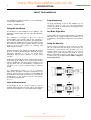


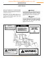

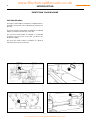

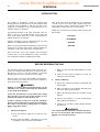
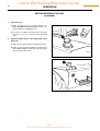

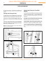
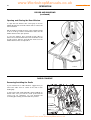
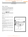


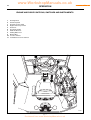

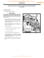


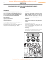

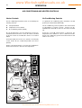
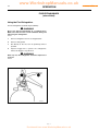

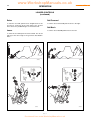
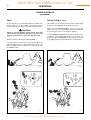

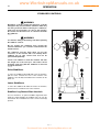

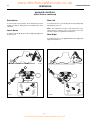


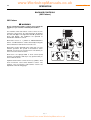

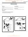
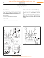


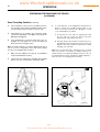
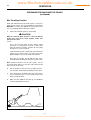
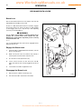


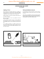
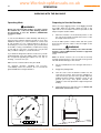


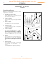
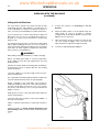


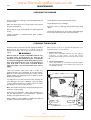

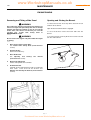


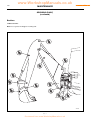
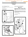
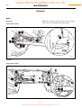


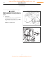
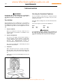
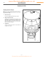
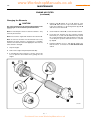
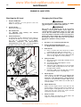
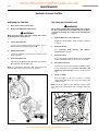
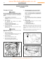


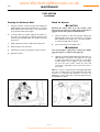
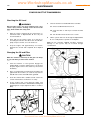
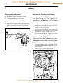
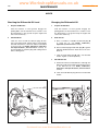


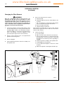
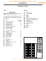


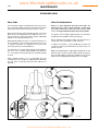
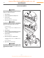

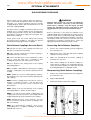

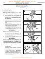
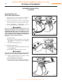


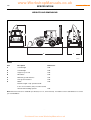


![Lifts Part 4: Operational Management [PDF 707Kb]](http://vs1.manualzilla.com/store/data/006003154_1-8f988a4c31a2e96372488ae8439271db-150x150.png)