1
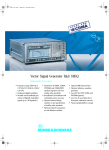
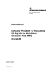
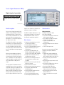
Vector Signal Generator SMIQ
Digital signals of your choice
With compliments
Helmut Singer Elektronik
www.helmut-singer.de [email protected]
fon +49 241 155 315
fax +49 241 152 066
Feldchen 16-24 D-52070 Aachen Germany
Photo 43304-3
Brief description
The B series of Signal Generator Family
SMIQ for analog and digital modulation
from Rohde&Schwarz is offering solutions for today and tomorrow. This series
particularly takes into account future
developments in the field of 3rd-generation digital mobile radio.
The SMIQ family comprises four models
which differ in their upper frequency limits. These feature a hitherto unrivalled
versatility regarding signal generation
and signal quality and are therefore ideal
for use in development and type-approval
testing.
With their outstanding price/performance ratio, these signal generators are
also economically attractive for applications in production. The wide frequency
range from 300 kHz to 6.4 GHz covers all
main radio bands including their IF
ranges.
The high-grade I/Q modulator fitted as
standard ensures minimum error vector
magnitude and high intermodulation suppression. Using modern digital signal
processor (DSP) technology, the versatile
concept allows the generation of highprecision digital modulation signals with
high bit rates without any limitations on
modulation modes or standards.
In addition to digital modulation, the signal generators provide the full range of
analog modulation modes as well as
simultaneous modulation capability.
Main features
• Frequency range 300 kHz to 2.2 GHz/
3.3 GHz/4.4 GHz/6.4 GHz
• Analog and digital modulation
• Versatile and broadband generation of
digitally modulated signals up to
18 Msymbol/s
• Generation of TDMA, CDMA, WCDMA and CDMA2000 standard signals to all main mobile radio standards
• Broadband I/Q modulator with outstanding vector accuracy
• Optional internal fading simulator to
test specifications of mobile radio
standards
• Optional internal noise generator and
distortion simulator
• Optional BER measurement
• Optional arbitrary waveform generator
• Low ACP for IS-95 CDMA and
W-CDMA (option)
• Low cost of ownership due to threeyear calibration intervals
• Future-oriented platform concept
• Unrivalled price/performance ratio
Characteristics
Digital modulation
Any digital modulation modes
(with option SMIQB20)
• Free choice of modulation mode from
ASK through to 256QAM
• Any kind of baseband filtering with
variable filter parameters
• Symbol rate adjustable up to
18 Msymbol/s
• Realtime coding of internal and external data
• Internal PRBS generators
Convenient burst generation for TDMA
standards (with option SMIQB20/
SMIQB11)
• TDMA mobile radio standards provided as standard GSM, GSM-EDGE,
DECT, NADC (IS-54C/IS-136), PDC, PHS
• Versatile external synchronization
capabilities
• Realtime processing of external and
internal data
• Generation of TDMA frames with versatile timeslot configuration
• Continuous PRBS sequences
• Optimization of burst shaping to
reduce spectra due to switching
• Realtime processing with external
data for BER tests
• Slot-by-slot modulation change for
TDMA
• Fast setting time for frequency (<3 ms)
and level (<2.5 ms)1 )
• Frequency hopping (500 μs)
• High spectral purity (typ. –130 dBc
Vector Signal Generator SMIQ
Overview of options
FM/ϕM Modulator
Data Generator (15 Mbit RAM)
Memory Extension, 32 Mbit
Fading Simulator (6 paths)
2nd Fading Simulator (6 paths)
Noise Generator and Distortion Simulator
Digital Modulation Coder
BER measurement
Digital Standard IS-95 CDMA
Digital Standard W-CDMA (NTT DoCoMo1.0, ARIB 0.0)
Digital Standard W-CDMA according to 3GPP (FDD)
Low ACP for IS-95 CDMA and W-CDMA
Extended Functions for W-CDMA 3GPP
Arbitrary Waveform Generator
Digital Standard IS-95 CDMA (with ARB SMIQB60)
Digital Standard CDMA2000 (with ARB SMIQB60)
SMIQB11 2 )
SMIQB12
SMIQB14
SMIQB15
SMIQB17
SMIQB20
SMIQB21
SMIQB42 3 )
SMIQB43 3)
SMIQB45 3)
SMIQB47
SMIQB48
SMIQB60
SMIQK11
SMIQK12
TDMA
To standard
Non-standard
CDMA IS-95
To standard
W-CDMA
To standard
CDMA2000
To standard
Fading
SM-B5
Application1 )
Reference Oscillator OCXO
(1 Hz) at 1 GHz and 20 kHz carrier off-
SM-B1
12
❍
❍
❍
●
●
❍
❍
❍
❍
❍
●
●
❍
❍
❍
●
❍
❍
❍
●
❍
❍
❍
❍
●
❍
❍
❍
●
❍
❍
●
❍
❍
❍
●
●
❍
set)
●
●
●
●
❍
❍
●
●
Vector modulation
❍
❍
❍
●
❍
❍
❍
❍
❍
❍
❍
❍
❍
❍
❍
❍
❍
❍
❍
❍
❍
❍
❍
❍
Analog modulation (AM, FM, ϕM)
❍
Fast setting time
1)
SMIQ02B/03B (SMIQ04B/06B) can be equipped with up to three (two) of the following options: SM-B5, SMIQB14,
SMIQB15 or SMIQB17
2)
Option SMIQB20 required
● = required
3)
Options SMIQB20 and SMIQB11 required
❍ = optional
Analog modulation
• Broadband AM with up to 30 MHz
modulation frequency
• I/Q modulation with 30 MHz modulation bandwidth (3 dB),
60 MHz RF bandwidth
• Unprecedented vector accuracy and
high intermodulation suppression
• Amplitude modulation
• Pulse modulation
• Optional frequency and phase modulation (SM-B5)
RF characteristics
• Wide output frequency range from
300 kHz to 6.4 GHz
• High (up to 16 dBm) and precise output
level (<0.5 dB)
• Calibrated RF level in range from
–140 dBm to –5 dBm
• RF, AF and level sweep (user-programmable)
Special options
Fading simulation
(options SMIQB14 and SMIQB15)
• Fading of internal or external I/Q signals conforming to mobile radio standards
• 6-path simulation can be enhanced to
12-path simulation (2-channel fading
also possible with second vector signal
generator)
• Rayleigh, Rice and lognormal fading
profiles can be selected independently
for each path
• Selectable path attenuation and delay
• Simulation of high speeds
• Preprogrammed fading profiles for
mobile radio standards GSM, NADC,
IS-95 CDMA and TETRA
• Frequency range of basic unit can be
fully utilized
Noise generator and distortion
simulator (option SMIQB17)
• Simulation of amplitude and phase
distortion (AM/AM and AM/ϕM characteristics)
• Distortion characteristics programmable from up to 30 input values
• Superimposed noise signals (AWGN)
• C/N ratio variable with high resolution
over a wide range
• Broad noise bandwidth
(10 kHz to 10 MHz)
1)
without switching the mechanical attenuators.
Vector Signal Generator SMIQ
Bit error rate measurements
(option SMIQB21)
• Up to 30 MHz clock rate
W-CDMA für 3GPP/FDD
(Option SMIQB45)
Software option SMIQB45 supports the
generation of downlink and uplink signals
in line with the 3GPP standard (FDD
mode). As the standardization process is
not yet completed, the functionality of
this option will continuously be adapted
to the relevant standard modifications
and expansions (for functionality see
specifications).
Low ACP for IS-95 CDMA and
W-CDMA (option SMIQB47)
• Specially designed for 1.2288 Mcps,
4.096 Mcps and 8.192 Mcps as well as
3.840 Mcps according to 3GPP
• Can be used with internal (option
SMIQB42/43/45/48) or external
CDMA/W-CDMA signals
• Typical W-CDMA adjacent-channel
power ratio (5 MHz offset, 3.84 Mcps):
–67 dBc (1 DPCH)
• Typical IS-95 CDMA adjacent-channel
power ratio (885 kHz offset): –78 dBc
(9 code channels)
Enhanced functions for W-CDMA
3GPP (FDD) digital standard
(Option SMIQB48)
This option expands the functionality of
option SMIQB45 W-CDMA 3GPP. It allows
the generation of up to four enhanced
channels that can be combined with the
standard channels.
• Very long signal sequences and continuous PRBS sequences (eg PN9) often
required for BER measurements can be
implemented for the channel under
test
• Use of externally precoded data or the
generation of long power control profiles for the DUT
• Testing the closed-loop power control
function of a mobile station
• Receiver and performance tests to
TS 25.101, TS 25.104, TS25.14. and
TS25.944
• Realistic simulation of W-CDMA scenarios
• Creation and insertion of bit errors into
the data of enhanced channels
• Insertion of block errors (BLERs) into
the channel-coded data
• Generation of W-CDMA signals of up
to 2 minutes repetition rate
Enhanced fading functions for
W-CDMA 3GPP (Option SMIQB49)
Option SMIQB49 extends the functionality of fading options SMIQB14/B15 to
include W-CDMA 3GPP channel simulation. It adds three new modes to the fading simulator so that all scenarios defined
in 3GPP Release 99 can be simulated:
• In fine delay mode, fading simulator
resolution is increased to 1 ns with up
to four paths being available
• In moving delay mode, two paths are
simulated: for one path the delay
remains constant, whereas for the
other path the delay varies continuously
• In birth-death mode, there are two
paths changing delay in steps in
accordance with the 3GPP channel
model
Digital standard IS-95 (Options
SMIQK11 and SMIQB60 (ARB))
In addition to generating IS-95 signals
with option SMIQB42, SMIQ in conjunction with SMIQB60 simulates CDMA signals to the North-American standard
IS-95A. Option SMIQK11 enables IS-95
functionality under WinIQSIM™.
• Up to eight complete base stations
comprising 64 code channels each are
available in forward link and up to 16
mobile stations in reverse link
• Channel power can be set independently for all code channels
• Adjacent-channel power can be calculated for 1. and 2. adjacent channel
and output as a spectral display
• CCDF trace can be displayed
Digital standard CDMA2000 (Options
SMIQK12 and SMIQB60 (ARB))
CDMA signals to the North-American
standard IS-2000 can be simulated by
means of software option SMIQK12 in
conjunction with Arbitrary Waveform
Generator SMIQB60. Option SMIQK12
enables CDMA2000 functionality under
WinIQSIM™.
The modes 1X direct spread, 3X direct
spread and 3X multicarrier (forward link
only) are available. In forward link four
base stations of max. 91 code channels
can be set, in reverse link four mobile stations of max. 13 code channels each.
Arbitrary Waveform Generator
SMIQB60
To further enhance the versatility of the
modulation coder, a dual-channel arbitrary waveform generator (ARB) with a
maximum clock rate of 40 MHz is available as an option. It can store up to
512 ksamples of externally computed I/Q
values.
The supplied WinIQSIM™ software
allows the calculation of arbitrary modulation signals, for example COFDM, multicarrier and noise, and downloading them
12
With compliments
Vector Signal Generator SMIQ
Helmut Singer Elektronik
www.helmut-singer.de [email protected]
fon +49 241 155 315
fax +49 241 152 066
Feldchen 16-24 D-52070 Aachen Germany
into SMIQ. Together with a convenient
data editor, WinIQSIM™ can calculate
any kind of TDMA frame configuration,
simulate impairments by superimposed
interference signals, etc.
Applications
• Type-approval testing of digital base
and mobile stations
• Base-station transmitter test
• Sensitivity measurements on digital
receivers
Specifications in brief
Frequency
Range SMIQ02B
SMIQ03B
SMIQ04B
SMIQ06B
Resolution
Reference frequency
Aging (after 30 days operation)
Temperature effect (0°C to 50°C)
Level
Range
SMIQ02B/03B
SMIQ04B/06B
Overranging without guarantee of
specs
Resolution
Total level uncertainty >−127 dBm 2) 3)
f ≤2 GHz
f >2 GHz to 4 GHz
f >4 GHz to 6 GHz
f >6 GHz
Frequency response at 0 dBm2) 3)
f ≤3.3 GHz
f >3.3 GHz
Spectral purity2)
Spurious
Harmonics at levels ≤10 dBm
(SMIQ02B/03B)
Harmonics at levels ≤7 dBm
(SMIQ04B/06B)
Broadband noise, carrier offset
>5 MHz
f >20 MHz to 450 MHz
f >450 MHz to 3040 MHz
f >3040 MHz to 3300 MHz
f >3300 MHz to 6400 MHz
Broadband noise, vector modulation,
(f >20 MHz) carrier offset >5 MHz
SSB phase noise, carrier offset 20 MHz,
1 Hz bandwidth
f = 20 MHz to 450 MHz
f = 1 GHz
f = 2 GHz
f = 3 GHz
f = 6 GHz
Sweep
RF sweep, AF sweep
Modes
• Selectivity measurements on digital
receivers
• Testing of equalizers
• Tolerance tests on digital systems
• Components tests
• Development of new digital
communication systems
Modulation
300 kHz to 2.2 GHz
300 kHz to 3.3 GHz
300 kHz to 4.4 GHz
300 kHz to 6.4 GHz
0.1 Hz
Standard
Option SM-B1
1 x 10⁻⁶/year
<1 x 10⁻⁹/day
–6
x
2 10
<5 x 10⁻⁸
−144 dBm to +13 dBm (PEP)1)
−144 dBm to +10 dBm (PEP)1)
up to16 dBm
0.1 dB or 0.01 dB
<±1 dB
<±1.5 dB
<±2 dB
<±2.5 dB
(typ. <±0.5 dB)
(typ. <±0.9 dB)
(typ. <±1.2 dB)
<1 dB
<±1.5 dB
(typ. <0.3 dB)
(typ. <±0.5 dB)
Internal modulation generator
Frequency range
Frequency error
Open-circuit voltage at LF socket
Vector modulation
Level accuracy with vector modulation, additional error with ALC OFF, relative to CW
Modulation inputs I and Q
Input voltage for full-scale input
Envelope control
Amplitude modulation2)
Modulation depth
Broadband amplitude modulation
Input voltage for 100% AM
Pulse modulation
On/off ratio
Rise/fall time(10/90%)
Pulse repetition frequency
Frequency modulation
Max. deviation
Phase modulation
<–30 dBc
<–30 dBc
Max. deviation
Digital modulation
CW
<–136 dBc
<–138 dBc
<−136 dBc
<−132 dBc
(typ.−142 dBc)
(typ.−144 dBc)
(typ.−142 dBc)
(typ.−138 dBc)
<−131 dBc
(typ. −137 dBc)
CW
Vector modulation
(dig. Mod.)
<–119 dBc
<–123 dBc
<–120 dBc
<–116 dBc
<–110 dBc
<–116 dBc
<–126 dBc
<−120 dBc
<−116 dBc
<–110 dBc
digital sweep in discrete steps
automatic, single shot, manual or external trigger, linear or logarithmic
0.1 Hz to 1 MHz
<1 x 10⁻⁴ + 0.012 Hz
1 mV to 4 V peak
<0.3 dB
I 2 + Q 2 = 0.5 V (1 V EMK with
50-Ω Source)
RF level can be controlled with an analog voltage of 0 V to 1 V via the POWER
RAMP input
internal, external AC/DC
0% to 100%
external DC
0.25 V peak
external
>80 dB
typ. 30 ns
0 Hz to 1 MHz
Option SM-B5
int., external AC/DC, two-tone with two
modulation channels FM1 and FM2
0.5/1/2/4 MHz depending on frequency
Option SM-B5
int., external AC/DC, two-tone with two
modulation channels ϕM1 and ϕM2
5/10/20/40 rad depend. on frequency
Option SMIQB20
internal, external, serial, ext. parallel
Predefined modulation settings
APCO C4FM, APCO CQPSK, CDPD, CT2, DECT, GSM, IRIDIUM, NADC, PDC, PHS,
TETRA, TFTS, PWT, ICO BPSK, ICO GMSK, ICO QPSK, GSM EDGE, CDMA IS-95,
W-CDMA, QPSK
Internal PRBS
selectable lengths: 29–1, 215–1, 216–1,
220–1, 221–1 and 223–1
Envelope control
internal or external
Range of function
1 ksymbol/s to 2.5 Msymbol/s
Modulation modes
ASK, FSK, GMSK, PSK, QAM
ASK, symbol rate
100 symbol/s to 18 Msymbol/s 1)
FSK, modulation modes
2FSK, 4FSK, 4FSK APCO, GFSK
100 bit/s to 7.5 Mbit/s1)
GMSK, bit rate
PSK, modulation modes
BPSK, QPSK, OQPSK, QPSK (IS-95),
OQPSK (IS-95), QPSK (ICO), QPSK (INMARSAT), π/4DQPSK,
π/4QPSK, 8PSK, 8PSK EDGE
QAM, modulation modes
16QAM, 32QAM, 64QAM, 256QAM
12
Speed range
Data generator
Option SMIQB11
Programmable data memory for modulation data, envelope-control and trigger
signals. The data generator can be operated only in conjunction with the optional modulation coder
Max. symbol rate
8.5 Msymbol/s
Operating modes
automatically repeating, single shot,
manually or externally triggered
Memory extension
Option SMIQB12
The data generator memory can be extended to max. 79 Mbit by fitting up to two
options SMIQB12.
Memory capacity
32 Mbit
Digital standards
GSM / EDGE
Frequency
Modulation
DECT
Frequency
Modulation
NADC
Frequency
Modulation
PDC
Frequency
Modulation
PHS
Frequency
Modulation
Options SMIQB20 and SMIQB11
according GSM standard
880 to 960 MHz/1710 to 2000 MHz
GMSK or 8PSK EDGE
(8PSK with 3π/8 Rotation)
according ETS300175-2 and ETS300176-1
1880 MHz to 1900 MHz
GFSK (Standard), π/4 DQPSK
according IS-54 and IS-136
824 to 894 MHz/1850 to 2000 MHz
π/4 DQPSK
according RCR STD-27
810 to 826 MHz/940 to 956MHz
1429 to 1453 MHz/1477 to 1501 MHz
π/4 DQPSK
according RCR STD-28
1895.0 MHz to 1918.1 MHz
π/4 DQPSK
Digital standard IS-95 CDMA
Option SMIQB42
According TIA standard IS-95A and J-STD-008
Frequency
824 to 894 MHz/1850 to 2000 MHz
Modulation
QPSK, OQPSK
Digital standard W-CDMA
Frequency
Modulation
Option SMIQB43 2)
1800 MHz to 2200 MHz
QPSK, OQPSK
Digital standard W-CDMA 3GPP (FDD) Option SMIQB45 3)
according 3GPP standard 3.4.0 (FDD)
3GPP (FDD) Version
optional 3.4.0, according technical
specifications 3GPP TS25.211 and
TS25.213
Frequency
1800 MHz to 2200 MHz
Simultanous modulation
Any combination is possible with the following exceptions:
– Simultaneous FM and ϕM
– Simultaneous digital modulation and vector modulation
Pulse modulation cannot be used together with level attenuation function LEV ATT (option SMIQB20)
Options for special applications
Fading simulation
paths and channels
with option SMIQB14
with options SMIQB14 and -B15
Path attenuation
Options SMIQB14, SMIQB15
6 paths, 1 channel
12 paths, 1 channel or 6 + 6 paths,
2 channels with second SMIQ through
simple retrofit
1) PEP = peak envelope power.
2) Data apply to RF ≥5 MHz unless specified otherwise and for ATTENUATOR MODE
NORMAL function.
3) Additional error with ALC OFF <0.3 dB.
0 dB to 50 dB
0 μs to 1600 μs
0.1 Hz to 1600 Hz
Path delay
Doppler shift
Vector Signal Generator SMIQ
v
9m
0, 03x10 ----2s
= -------------------------------min
f RF
9m
479x10 ----2sv max = ---------------------------f RF
Rayleigh fading, pseudo noise intervall
Rice fading
Power ratio4)
Frequency ratio
Lognormal fading, Suzuki fading
Standard deviation
Correlation
>372 h
−30 dB to +30 dB
−1 to +1
0 dB to 12 dB
paths 1 to 6 with paths 7 to 12
Enhanced fading functions for
Option SMIQB49
W-CDMA 3GPP
The following data deviate from the specifications for SMIQB14/SMIQB15
Fine delay mode
Number of paths
2 (with SMIQB14),
4 (with SMIQB14 + SMIQB15)
Rayleigh, pure Doppler
Profiles
Delay, resolution
25 ns to 1637 μs, 1 ns
Moving delay mode
2
Number of paths
0 to 1000 μs (in 50 ns steps)
Delay, path 1
delay path 1 + delay variation (peak-peak)
Delay, path 2
x sin ( 2pt /variation period)
150 ns to 50 μs
Delay variation (peak-peak)
10 s to 500 s
Variation period
<1 ns
Delay step size
Birth-death mode
Number of paths
2
Profiles
pure Doppler
Delay
5 μs to 1000 μs
Delay range
5 μs to +5 μs (not variable)
Delay grid
1 μs (not variable)
Hopping dwell
100 ms to 5 s
Noise and distortion simulation
Distortion simulator
Distortion characteristic
Option SMIQB17
AM/AM and AM/ϕM distortion of
modulation signal
each characteristic programmable by
entering up to 30 input values via IEEE/
IEC bus or by entering up to five polynomial coefficients
Noise generator (AWGN)
Distribution density
Crest-Faktor
C/N
Gaussian, statistically indep. for I and Q
14 dB
−30 dB to 30 dB
Bit error rate measurement
Option SMIQB21
Pseudo-random bit sequences (PRBS) 29-1, 211-1, 215-1, 216-1, 220-1, 221-1,
223-1
Measurement time
selectable through maximum number
of data bits or bit errors (max. 231 bits
each), continuous measurement
Measurement result
BER in ppm, % or decade values (if selected number of data bits or bit errors
is attained) status displays: not synchronized, no clock, no data
Improved adjacent-channel power Option SMIQB47
ratio for W-CDMA and CDMA IS-95
Selectable baseband filters to improve ACP values (values see at Digital Standards CDMA/W-CDMA)
Enhanced functions for digital
standard W-CDMA 3GPP (FDD)
3GPP (FDD) version
Option SMIQB48
3.4.0 to 3GPP technical specifications
TS25.101, TS25.104, TS25.141,
TS25.211 and TS25.213
Vector Signal Generator SMIQ
Enhanced Channels
Channels of W-CDMA system in SMIQ that offer enhanced functionality compared with standard channels of option SMIQB45.
Can be used in downlink for max. four DPCHs and in uplink for one DPCCH and
max. three DPDCHs. All DPCHs or DPDCHs have the same symbol rate.
Enhanced functions at a glance:
• Sequences of up to 1042 frames
• Data lists for data fields and TPC field
• External power control
• Channel coding
• Bit error insertion
• Block error insertion
Simulation of realistic noise scenarios
• Orthogonal channel noise simulation (OCNS)
• Additional mobile stations
Arbitrary waveform generator
Waveform memory, interpolation
Output memory
Length of waveform
Resolution
Downloading time for 512k I/Q samples
Nonvolatile memory
Number of blocks
Option SMIQB60
1 to 524216 in steps of one sample
12 bit
4s
22 (one waveform occupies at least one
block)
24 from firmware version 5.30
65527
0.375 x clock rate
Block size
Interpolation
Interpolation bandwidth (-0.1dB)
Repetitive spectra suppression through
analog filter
>70 dB
Clock generation
Clock rate
Resolution
Clock mode
Signal output, channels
Output level (EMF, peak)
Normal mode
Manual mode
Level difference between channels
DC offset
Frequency response
Magnitude up to 12 MHz/10 MHz
Group delay up to 10 MHz
I/Q imbalance
Magnitude up to 10 MHz
Group delay up to 10 MHz
SFDR (sinewave 1 MHz, clock 4 MHz,
measurement range up to 12 MHz)
Trigger modes
Trigger source
Trigger outputs
Delay
On time
Off time
Level
1 kHz to 40 MHz
0.1 Hz
internal or external
2 (I and Q)
SQRT(I2 + Q2) = 1 V, 50 Ω
–6 dB to 0 dB referred to 1 V, setting
range up to +3 dB
<0.2% at 1 kHz 1)
<–54 dB in normal mode 1)
<1 dB/typ. 0.1 dB
typ. 1 ns
typ. 0.05 dB
typ. 0.5 ns
>60 dB
auto, retrig, armed auto, armed retrig
internal or external
2
0 to 524216 samples
1 to 524215 samples
1 to 524215 samples
TTL
1) Spectral components exceeding max. IQ bandwidth will be suppressed.
2) Cannot be fitted together with Digital Standard W-CDMA 3GPP (option SMIQB45).
3) Cannot be fitted together with Digital Standard W-CDMA NTT DoCoMo (option
SMIQB43).
4) Ratio of discrete and distributed component.
5) Contrast of LCD lower at higher temperature.
General data
Memory for instrument settings
50 storable settings
List Mode
Frequency and level values can be stored in a list and set in an extremely
short time; permissible level variation: 90 dB
Max. number of channels
2000
Remote control
IEC 625 (IEEE 488)
Command set
SCPI 1993.0
Power supply
90 V to 265 V (AC), 50 Hz to 400 Hz,
autosetting to AC supply, max. 300 VA
Dimensions (W x H x D)
435 mm x 192 mm x 460 mm
Weight
25 kg when fully equipped
Ordering information
Vector Signal Generator
300 kHz to 2.2 GHz
300 kHz to 3.3 GHz
300 kHz to 4.4 GHz
300 kHz to 6.4 GHz
SMIQ02B
SMIQ03B
SMIQ04B
SMIQ06B
Accessories supplied
power cable, operating manual
1125.5555.02
1125.5555.03
1125.5555.04
1125.5555.06
Options
Reference Oscillator OCXO
SM-B1
1036.7599.02
FM/ϕM Modulator
SM-B5
1036.8489.02
Data Generator
SMIQB11 1085.4502.04
Memory Extension, 32 Mbit
SMIQB12 1085.2800.04
Fading Simulator, 6 paths
SMIQB14 1085.4002.02
Second Fading Simulator for
12 paths or 2 channels
SMIQB15 1085.4402.02
Noise Generator and Distortion Simulator
SMIQB17 1104.9000.02
RF and AF Rear Connectors
SMIQB19 1085.2997.02
Modulation Coder
SMIQB20 1125.5190.02
BER Measurement
SMIQB21 1125.5490.02
Digital Standard IS-95 CDMA
SMIQB42 1104.7936.02
Digital Standard W-CDMA acc. to NTT DoCoMo 1.0, SMIQB43 1104.8032.02
ARIB 0.0 standard
Digital Standard W-CDMA according to 3GPP (FDD) SMIQB45 1104.8232.02
Low ACP for IS-95 CDMA and W-CDMA
SMIQB47 1125.5090.02
Modification Kit for Low ACP (factory-fitted only)
SMIQU47 1125.5149.02
Extended Functions for W-CDMA (3GPP)
SMIQB48 1105.0587.02
Extended Fading Functions for W-CDMA (3GPP)
SMIQB49 1105.1083.02
Arbitrary Waveform Generator incl. WinIQSIM™
SMIQB60 1136.4390.02
TETRA T1 Simulator
SMIQ-K8 1136.4290.02
Digital Standard IS-95 CDMA (software for SMIQB60) SMIQK11 1105.0287.02
Digital Standard CDMA2000 (software for SMIQB60) SMIQK12 1105.0435.02
Dig. Standard W-CDMATDD mode (3GPP) (for option SMIQK13 1105.1231.02
SMIQB60)
Digital Standard TD-SCDMA (software for SMIQB60) SMIQK14 1105.1338.02
OFDM Signal Generation, HIPER LAN/2
SMIQK15 1105.1531.02
Additional hint: SMIQ02B/03B (SMIQ04B/06B) can be equipped with up to three
(two) of the following options: SM-B5, SMIQB14, SMIQB15, SMIQB17
Application software
Generation of data and control lists
Bluetooth signals for SMIQ
User mappings and user filters for SMIQ
SMIQ-K1 *)
SMIQ-K5 *)
User Mod *)
*) available on www.rohde-schwarz.com
Extras
19" Adapter
Service Kit
BNC Adapter for rear panel,
D type connector PAR DATA
90° Power Splitter
Trolley for Transit Case
Transit Case
Service Manual SMIQ
Instrument upgrades
SMIQ02B to SMIQ03B
SMIQ03B to SMIQ04B
SMIQ04B to SMIQ06B
ZZA-94
SM-Z3
0396.4905.00
1085.2500.02
SMIQ-Z5
SMIQ-Z9
ZZK-1
ZZK-944
1104.8555.02
1104.9580.02
1014.0510.00
1013.9366.00
1085.2445.24
SMIQU03
SMIQU04
SMIQU06
1125.5855.03
1125.5855.04
1125.5855.06