1
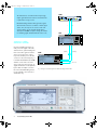
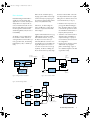
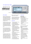
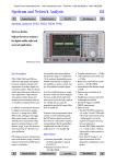
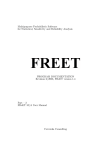
abfs_e.fm Seite 1 Freitag, 11. Februar 2000 10:46 10
Baseband Fading Simulator ABFS
Saving costs through real-world fading tests
• 2 fading channels
(4 with option ABFS-B2)
• 12 propagation paths
(24 with option ABFS-B2)
• Universal use in research,
development and production
• Simulation of present and
future communication systems
thanks to flexible concept
• Receiver tests at I/Q level together with a baseband source
• Ease of operation
• High reliability
abfs_e.fm Seite 2 Freitag, 11. Februar 2000 10:46 10
AMIQ
The characteristics of a radio channel may strongly
impair signal transmission between a transmitter and
I/Q MODULATION GENERATOR
ON
CONTROL
.
AMIQ
1110.2003.02
I
RUNNING
Q
in particular a moving receiver.
MADE IN GERMANY
Baseband Fading Simulator ABFS generates signals
which simulate real receive conditions in mobile appli-
I
Q
cations. Thus, the response of receivers under realworld conditions can be checked already during
development and QM acceptance testing. The simulation of fading signals at baseband level reduces costs.
ABFS
Advantages of fading
simulation in baseband
Conventional fading simulators normally convert the signal of the radio
channel to the IF, perform fading and
then reconvert the signal to its RF fre-
SMIQ
I (faded)
Q (faded)
quency. It is however less costly to
loop in the simulator prior to the first
conversion to the carrier frequency, ie
to simulate at baseband level (I and Q)
and then convert to the correct fre-
RF OUT
quency in the test system (see Fig. 2).
Signals will therefore not be impaired
by the effects of multiple conversion.
Due to this baseband fading simulation an upgrade to new networks or
standards is easy.
2
Baseband Fading Simulator ABFS
Fig. 1: Fading of a baseband signal from AMIQ with Fading Simulator ABFS
abfs_e.fm Seite 3 Freitag, 11. Februar 2000 10:46 10
ABFS can also simulate frequency
The basic model of ABFS comes with
hopping systems. ABFS is fast enough
two independent channels for 6-path
Baseband Fading Simulator ABFS is
to follow the frequency hopping of a
fading. The two channels can be inter-
suitable for universal mobile radio
test system for example within a frame
connected as follows (see Fig. 3):
applications in research, development
of 4,616 ms (GSM frame time).
Fit for the future
• Distribution of an input to two out-
and production. It comprises all scenarios and statistical models for simu-
Furthermore, an offset voltage for
puts (eg with different fading pro-
lating sporadic fading as specified in
each I and Q input or output can be
files). This feature makes it possible
the test regulations of mobile radio
entered to compensate external DC
to simulate the signal of two anten-
standards (eg GSM, IS-54/US-136 or
offset voltages.
nas with different characteristics or
IS-95 CDMA).
frequency diversity methods
Together with a baseband source (eg
• Simulation of two channels with in-
The flexible concept of ABFS allows
I/Q Modulation Generator AMIQ
dividual profiles and addition at
the simulation of radio channels of
from Rohde & Schwarz, see Fig. 1 on
output. Cell change or superposi-
existing and future communication sys-
the left) receiver tests can be per-
tion of interferers can be tested with
tems (eg mobile radio, broadcasting,
formed at I/Q level even if the corre-
this configuration
flight telephone, WLL, or WLAN sys-
sponding RF link is not available. Dur-
tems).
ing the development of receivers or
channel with 12 propagation
correction circuits in the receiver (eg
paths is obtained (Fig. 4 gives a
equalizer), the effects of fading can
more detailled insight how the fad-
thus be checked at a very early stage.
ing simulator works).
Test signal
(incl. channel simulation)
• Coupling of two channels so that a
Output
I,Q
Channel 1
Input
I,Q
Channel 1
6-path fading
Noise generator
(optional)
Test system
I/Q - source
I/Q
- modulator
I,Q output
I,Q input
+
6-path fading
Fading Simulator
I,Q
Channel 2
I,Q
Channel 2
ABFS
Fig. 2: Fading simulation in baseband
Fig. 3: Interconnections of ABFS
Fig. 4: Schema of fading simulator
DSP
fading
profiles
path 1
gain
variable
delay
x
path 2
I,Q
gain
variable
delay
A
I,Q
x
D
+
.
.
.
+
A
+
I,Q
Noise
generator
path 6
variable
delay
ABFS-B1 (optional)
D
gain
x
from second
fading simulator
Baseband Fading Simulator ABFS
3
abfs_e.fm Seite 4 Freitag, 11. Februar 2000 10:46 10
High versatility by options
Typical Rayleigh
fading profile
Noise Generator ABFS-B1 adds a
noise source to the output of the first
channel (see Fig. 3) so that noise can
be simulated in the frequency band
used. The noise generator can be
switched on or off irrespective of the
operating modes of the basic version.
Second Fading Simulator ABFS-B2
offers two extra channels with the
same characteristics in addition to the
two channels of the basic model.
Second Noise Generator ABFS-B3 represents an additional noise source for
a further output. This second noise
generator is either assigned to the second channel of the basic ABFS (with
first noise generator ABFS-B1 for the
Rayleigh fading
(Doppler spectrum),
generated at a speed
of 180 km/h
(RF = 1.8 GHz)
first channel) or to the first channel of
the second fading simulator ABFS-B2.
Fading profiles of the Rayleigh, Rician,
Pure Doppler, Lognormal or Suzuki
method can be assigned to each of the
propagation paths irrespective of the
selected circuit (see Fig. 3).
In addition to the fading profiles mentioned, the following parameters can
be defined for each propagation path:
• Path attenuation
• Delay time
• Doppler frequency or speed be-
Why fading tests?
• Coupling to another channel
Interleaving is employed to overcome the problem of losing large
tween transmitter and receiver
Short-time signal fading, as caused
parts of the messages.
by multipath propagation, strongly
Many fading models (eg GSM Rural
affects the error rate of the received
Resistance to fading is an essential
Urban, Typical Urban) have already
signal due to the short symbol peri-
quality criterion of digital mobile
been programmed in ABFS. The user
ods in digital mobile radio
radio systems and means a considerable competitive advantage for
can quickly recall these default settings and also modify the parameters.
Modern digital systems overcome
the manufacturer.
these problems with the aid of
appropriate error control coding
Tests with real-world signals using
methods as well as algorithms for
fading simulators are a must to spot
delay equalizing.
the weak points in new concepts at
an early stage so that appropriate
modifications can be made.
Baseband Fading Simulator ABFS
4
abfs_e.fm Seite 5 Freitag, 11. Februar 2000 10:46 10
Noise power level in relation to fullscale level
Range
Resolution
Error
Specifications
IQ inputs and outputs
Impedance
50 Ω
Input voltage for full-scale level
Residual DC voltage at output
Insertion loss of basic unit
I + Q = 0.5 V
<2 mV, fine tuning by software
0.3 dB
Insertion loss between input and
output
1
2
2
4
Output spectrum
Bandwidth
Frequency response
up to 0.7 x system bandwidth
(max. 5 MHz)
RF system bandwidth4)
Setting range
Resolution
Memory for device settings
Storable settings
Frequency response
Output level at full-scale level (AC)
2
Fading simulation
Number of propagation paths and
fading channels
Basic model
with option ABFS-B2
Insertion loss between input and
output at 0 dB path attenuation
Frequency response
up to 5 MHz offset from carrier
frequency (corresponding to
10 MHz system bandwith)
Path attenuation
Range
Resolution
Error in range 0 to 20 dB
Path delay
Range
Resolution
Error
Doppler shift
Frequency range
Speed range
min. 9 dB
Remote control
System
Command set
Connector
IEC/IEEE-bus address
Interface functions
+0.1 dB to −0.6 dB
0 to 50 dB
0.1 dB
<0.3 dB
0 to 1600 µs
50 ns
<5 ns
General data
Power supply
0.1 to 1600 Hz
0.03 ⋅ 10 9 m / s 2
fRF
v max =
479 ⋅ 10 9 m / s 2
fRF
For example at fRF = 1 GHz:
vmin = 0.1 km/h, vmax = 1724 km/h
Resolution
Error
Rayleigh fading
Pseudo noise interval
Deviation from theoretical CPDF1)
at Pavg = 0 dB
in range −20 dB to +10 dB
in range −30 dB to −20 dB
Rice fading
Power ratio2)
Range
Resolution
Frequency ratio
Range
Resolution
Lognormal fading, Suzuki fading
Standard deviation
Range
Resolution
0.1 km/h, m/s, mph
<0.13 %
>372 h
Correlation
Range for magnitude
Resolution
Range for phase
Resolution
RF setting
Range (for each fading channel)
Frequency hopping mode
Interface
Addressing of frequency list
Electromagnetic compatibility
Environmental conditions
Operating temperature range
Storage temperature range
Climatic resistance
Mechanical resistance
Vibration, sinusoidal
<1 dB, typ. <0.3 dB
<2 dB, typ. <0.3 dB
Vibration, random
Shock
−30 dB to +30 dB
0.1 dB
Safety
Dimensions (W x H x D)
Weight
−1 to +1
0.05
0 to 12 dB
1 dB
lmin to 200 m,
Local constant
2
2
I + Q = 0.5 V (= 4 dBm)
2
channel with 12 paths or
channels with 6 paths each
channels with 12 paths each or
channels with 6 paths each
v min =
−17 to −50 dBfs
0.05 dB
<0.3 dB
lmin =
12 ⋅ 10 9 m / s
fRF
paths 1 to 6 with paths 7 to 12 of a
channel (A or B)
0 to 100 %
5%
0 to 360°
1°
setting of the RF results in an automatic calculation and display of the
Doppler frequency according to the
set motion speed3)
5 MHz to 8.5 GHz
RF can be stored in a list and quickly
set via a serial interface
RS 232, 1 byte with start and stop bit
8 or 16 bit as address for each fading channel
Setting time after frequency change
<3.5 ms
during Rayleigh fading
Noise generator with options ABFS-B1 or ABFS-B3
Amplitude distribution
Gaussian, statistically independent for
I and Q
Crest factor
14 dB
0, 6, 12 to 42 dB
white noise
depending on set system bandwidth
<0.5 dB
bandwidth determining noise power
10 kHz to 10 MHz
1%
50
−0.2 dB to −0.6 dB
IEC 625 (IEEE 488)
SCPI 1993.0
Amphenol 24-pin
0 to 30
SH1, AH1, T6, L4, SR1, RL1, PP1,
DC1, DT1, C0
90 V to 132 V (AC), 47 Hz to
440 Hz, 180 V to 265 V (AC), 47 Hz
to 440 Hz, autoranging,
max. 300 VA
meets EN 50081-1 and EN 50082-2
0 to 45°C,
meets IEC68-2-1 and IEC68-2-2
−40 to +70°C
95% rel. humidity, cyclic test at
+25/+40°C, meets IEC68-2-30
5 Hz to 150 Hz, max. 2 g at 55 Hz,
55 Hz to 150 Hz, 0.5 g const.,
meets IEC68-2-6,
IEC1010-1 and
MIL-T-28800D class 5
10 Hz to 300 Hz,
acceleration 1.2 g (rms)
40 g shock spectrum,
meets MIL-STD-810D,
MIL-T-28800D, class 3 and 5
meets EN 61010-1
435 mm x 192 mm x 460 mm
20 kg when unit is fully equipped
Ordering information
Baseband Fading Simulator
Accessories supplied
ABFS
power cable,
operating manual
1114.8506.02
Options
Noise Generator
Second Fading Simulator
Second Noise Generator
ABFS-B1
ABFS-B2
ABFS-B3
1115.0009.02
1115.0309.02
1115.0609.02
Recommended extras
19’’ Rack Adapter
Service Kit
Trolley
Transit Case
Service Manual
ZZA-94
SM-Z3
ZZK-1
ZZK-944
ABFS
0396.4905.00
1085.2500.02
1014.0510.00
1013.9366.00
1114.8564.94
1)
2)
3)
4)
CPDF: cumulative probability distribution function
Ratio between discrete and distributed component
The phase differences between paths caused by different settings of path delay
are taken into account when the RF is modified. This applies to frequency hopping mode only
0.5 x system bandwidth is used for baseband
Certified Quality System
ISO 9001
DQS REG. NO 1954
Baseband Fading Simulator ABFS
5
PD 757.5466.21 ⋅ Baseband Fading Simulator ABFS ⋅ Trade names are trademarks of the owners ⋅ Subject to change ⋅ Data without tolerances: typical values
Printed in Germany
0200 (Bu we)
abfs_e.fm Seite 6 Freitag, 11. Februar 2000 10:46 10
ROHDE&SCHWARZ GmbH & Co. KG ⋅ Muehldorfstrasse 15 ⋅ 81671 Munich, Germany ⋅ P.O.B. 8014 69 ⋅ 81614 Munich, Germany ⋅ Telephone +49894129-0
www.rohde-schwarz.com ⋅ CustomerSupport: Tel. +491805124242, Fax +4989 4129-3777, E-mail: [email protected]