1
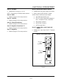
C70
CONVECTION MICROWAVE OVEN
SERVICE AND REPAIR MANUAL
BLODGETT OVEN COMPANY
www.blodgettcorp.com
50 Lakeside Avenue, Box 586, Burlington, Vermont 05402 USA Telephone (800) 331-5842, (802) 860-3700 Fax: (802)864-0183
PN T0582 Rev F (3/01)
E 2000 --- G.S. Blodgett Corporation
TABLE OF CONTENTS
READ THIS FIRST . . . . . . . . . . . . . . . . . . . . . . . . . . . . . . . . . . . . . . . . . . . . . . . . . . . . . . . . .
i
Important Safety Instructions . . . . . . . . . . . . . . . . . . . . . . . . . . . . . . . . . . . . . . . . . . . . . . .
ii
Precautions to Avoid Possible
Exposure to Excessive Microwave Energy . . . . . . . . . . . . . . . . . . . . . . . . . . . . . . . . . . . .
iii
Precautions to be Observed Before and During
Servicing to Avoid Possible Exposure to Excessive Microwave Energy . . . . . . . . . . .
iv
Grounding Instructions . . . . . . . . . . . . . . . . . . . . . . . . . . . . . . . . . . . . . . . . . . . . . . . . . . . . .
v
RF Interference Considerations . . . . . . . . . . . . . . . . . . . . . . . . . . . . . . . . . . . . . . . . . . . . .
vi
Section 1
Installation Specs
Oven Description . . . . . . . . . . . . . . . . . . . . . . . . . . . . . . . . . . . . . . . . . . . . . . . . . . . .
Installation . . . . . . . . . . . . . . . . . . . . . . . . . . . . . . . . . . . . . . . . . . . . . . . . . . . . . . . . .
Section 2
Cleaning & Operating
Basic Cleaning Procedures . . . . . . . . . . . . . . . . . . . . . . . . . . . . . . . . . . . . . . . . . . .
Oven Cavity Filter Cleaning . . . . . . . . . . . . . . . . . . . . . . . . . . . . . . . . . . . . . . . . . . .
Glossary of Common Operating Terms & Error Messages . . . . . . . . . . . . . . . .
Operational Flow Chart . . . . . . . . . . . . . . . . . . . . . . . . . . . . . . . . . . . . . . . . . . . . . .
Programming Flow Chart . . . . . . . . . . . . . . . . . . . . . . . . . . . . . . . . . . . . . . . . . . . . .
Section 3
3---1
3---2
Electrical Compartment
Key Sequence of Operation --- Failure Mode Analysis . . . . . . . . . . . . . . . . . . . .
Electrical Component Locations . . . . . . . . . . . . . . . . . . . . . . . . . . . . . . . . . . . . . . .
Electrical Component Description with Voltage Information . . . . . . . . . . . . . . .
Door Switches and Circuit Breakers . . . . . . . . . . . . . . . . . . . . . . . . . . . . . . . . . . .
Door Switch Adjustment . . . . . . . . . . . . . . . . . . . . . . . . . . . . . . . . . . . . . . . . . . . . .
Door Removal and Replacement . . . . . . . . . . . . . . . . . . . . . . . . . . . . . . . . . . . . . .
C70 Schematic . . . . . . . . . . . . . . . . . . . . . . . . . . . . . . . . . . . . . . . . . . . . . . . . . . . . .
Section 5
2---1
2---2
2---3
2---4
2---6
Test
Test Function Quick Reference . . . . . . . . . . . . . . . . . . . . . . . . . . . . . . . . . . . . . . . .
Test Function Detailed Description . . . . . . . . . . . . . . . . . . . . . . . . . . . . . . . . . . . . .
Section 4
1---1
1---1
4---1
4---2
4---3
4---5
4---6
4---9
4---12
Convection Circuit
Catalytic Converter . . . . . . . . . . . . . . . . . . . . . . . . . . . . . . . . . . . . . . . . . . . . . . . . . .
Convection Element and Thermocouples . . . . . . . . . . . . . . . . . . . . . . . . . . . . . . .
Thermoelectric Voltage in Millivolts --- Type K Thermocouple . . . . . . . . . . .
Convection (Blower) Motor Operation . . . . . . . . . . . . . . . . . . . . . . . . . . . . . . . . . .
Blower Motor Controller Fault Codes & Troubleshooting . . . . . . . . . . . . . . . . . .
5---1
5---2
5---3
5---4
5---5
TABLE OF CONTENTS
Section 6
Microwave Circuit
Measuring for Microwave Radiation Leakage . . . . . . . . . . . . . . . . . . . . . . . . . . .
Magnetron Circuit . . . . . . . . . . . . . . . . . . . . . . . . . . . . . . . . . . . . . . . . . . . . . . . . . . .
Magnetron Testing . . . . . . . . . . . . . . . . . . . . . . . . . . . . . . . . . . . . . . . . . . . . . . . . . .
Magnetron Removal and Replacement . . . . . . . . . . . . . . . . . . . . . . . . . . . . . . . . .
Component Testing . . . . . . . . . . . . . . . . . . . . . . . . . . . . . . . . . . . . . . . . . . . . . . . . . .
Transformer Specifications . . . . . . . . . . . . . . . . . . . . . . . . . . . . . . . . . . . . . . . . . . .
Control Circuit Board . . . . . . . . . . . . . . . . . . . . . . . . . . . . . . . . . . . . . . . . . . . . . . . .
6---1
6---2
6---3
6---3
6---4
6---5
6---6
READ THIS FIRST
TECHNICAL SUPPORT PHONE NUMBER
1-888-992-6624
This Service and Repair manual is set up for use by qualified technicians only. If you are unfamiliar with this oven, call the factory at the toll free number above for technical assistance. Technical
support can be reached 24 hours a day, seven days a week.
Before working on the Acellis C-70 oven you must first read the safety instructions on the following
pages. The Accellis C-70 is a combination convection/microwave oven. While servicing this oven, an
RF meter must be used at all times to check for microwave leakage. This RF reading must be recorded
on your work invoice.
Very often poor cleaning will result in microwave leakage. Please refer to the first two sections of this
manual (INTRODUCTION and CLEANING & OPERATION) for information on the proper cleaning procedures.
Before removing the metal skin to access the electrical components in this oven, the power must be
shut off and the oven unplugged. Wait at least one full minute before removing the oven skin so that
the magnetron circuit can self-discharge. FAILURE TO DO SO MAY RESULT IN DEATH OR SERIOUS
INJURY.
This oven has a one time registration feature on initial start-up. The Accellis C-70 will not operate until
you have called and registered the oven location and phone number with technical support. Upon registration, an access code will be issued. Be sure that you have the location of the installation site and
phone number before calling for registration.
This manual is divided into seven (7) chapters as follows:
1. INSTALLATION SPECS --This chapter includes oven specifications and the parameters for
proper installation.
2. CLEANING & OPERATION --- Improper cleaning can and will affect the operation of this oven. This
chapter includes a brief description of the cleaning and operation procedures of the oven and the procedure to edit or change a cooking
program.
3. TEST --This chapter details the Test Mode, which allows the technician to
operate individual components or section of the Accellis C-70 oven.
Using this feature will isolate most electrical troubleshooting
problems.
4. ELECTRICAL COMPARTMENT --- This chapter identifies the electrical compartment components and
provides voltage information. Use the key to help isolate electrical
troubleshooting problems.
5. CONVECTION &
CATALYTIC CONVERTER --This chapter provided information on the convection and blower
motor speed control. Removal and cleaning of the catalytic converter are also provided.
6. MICROWAVE CIRCUIT --This chapter includes information on the microwave circuit and stirrer motor.
i
IMPORTANT SAFETY INSTRUCTIONS
WHEN USING ELECTRICAL APPLIANCES, THE FOLLOWING
BASIC SAFETY PRECAUTIONS SHOULD BE STRICTLY ADHERED TO:
WARNING!!
To reduce the risk of burns, electric shock, fire, injury to persons or exposure to excessive
microwave energy:
7. Read all instructions before using the appliance.
8. Read and follow the specific PRECAUTIONS TO AVOID POSSIBLE EXPOSURE TO EXCESSIVE
MICROWAVE ENERGY found on page iii.
9. This appliance must be grounded. Connect only to properly grounded outlet. See GROUNDING
INSTRUCTIONS found on page iv.
10. Install or locate this appliance only in accordance with the provided installation instructions.
11. Some products such as whole eggs and sealed containers --- for example, closed glass jars --- may
explode and SHOULD NOT be heated in this oven.
12. Use this appliance only for its intended use as described in the manual. DO NOT use corrosive
chemicals or vapors in this appliance. This type of oven is specifically designed to heat, cook, or
dry food. It is NOT designed for industrial or laboratory use.
13. Children SHOULD NOT use this appliance.
14. DO NOT operate this appliance if it has a damaged cord or plug, if it is not working properly, or if
it has been damaged or dropped. See POWER SUPPLY CORD REPLACEMENT found on page
iv.
15. This appliance should be serviced only by qualified service personnel. Contact the nearest authorized service facility for examination, repair or adjustment.
16. DO NOT cover or block any openings on the appliance.
17. DO NOT store this appliance outdoors. DO NOT use this product near water --- for example, near
a kitchen sink, in a wet basement, or near a swimming pool.
18. DO NOT immerse cord or plug in water.
19. Keep cord away; from heated surfaces.
20. DO NOT let cord hang over edge of table or counter.
21. DO NOT use a water jet for cleaning.
22. See the Maintenance section of this manual.
23. To reduce the risk of fire in the oven cavity:
a.) DO NOT overcook food. Carefully attend appliance if paper, plastic, or other combustible materials are placed inside the oven to facilitate cooking.
b.) Remove wire twist ---ties from paper or plastic bag in oven.
c.) If materials inside the oven should ignite, keep oven door closed, turn oven off, and disconnect
the power cord, or shut off power at the fuse or circuit breaker panel.
d.) DO NOT use the cavity for storage purposes. DO NOT leave paper products, cooking utensils,
or food in the cavity when not in use.
SAVE THESE INSTRUCTIONS
ii
PRECAUTIONS TO AVOID POSSIBLE
EXPOSURE TO EXCESSIVE MICROWAVE ENERGY
1. DO NOT attempt to operate this oven with the door open since open---door operation can result
in harmful exposure to microwave energy. It is important not to defeat or tamper with the safety interlocks.
2. DO NOT place any object between the oven front face and the door or allow soil or cleaner residue
to accumulate on the sealing surfaces.
3. DO NOT operate the oven if it is damaged. It is particularly important that the oven door close properly and that there is no damage to the:
a.) Door (bent).
b.) Hinges and latches (broken or loosened).
c.) Door seals and sealing surfaces.
4. The oven SHOULD NOT be adjusted or repaired by anyone except properly qualified service personnel.
SAVE THESE INSTRUCTIONS
iii
PRECAUTIONS TO BE OBSERVED BEFORE
AND DURING
SERVICING TO AVOID POSSIBLE EXPOSURE
TO EXCESSIVE MICROWAVE ENERGY
1. DO NOT operate or allow the oven to be operated with the door open.
2. Make the following safety checks on all ovens to be serviced before activating the magnetron or
other microwave source, and make repairs as necessary:
a.) Interlock operation.
b.) Proper door closing.
c.) Seal and sealing surfaces (arcing, wear, and other damage).
d.) Damage to or loosening of hinges and latches.
e.) Evidence of dropping or abuse.
3. Before turning on microwave power for any service test or inspection within the microwave generating compartments, check the magnetron, wave guide, or transmission line, and cavity for proper
alignment, integrity, and connection.
4. If the oven is operative prior to servicing, a microwave emission check should be performed prior
to servicing the oven. Refer to page NO TAG of this manual for microwave leakage testing procedure.
5. Any defective or mis-aligned components in the interlock, monitor, door seal, and microwave generation and transmission systems shall be repaired, replaced, or adjusted by procedures described in this manual before the oven is released to the owner.
6. A microwave leakage check to verify compliance with the Federal Performance Standard MUST
BE performed on each oven prior to release to the owner. Refer to page NO TAG of this manual
for microwave leakage testing procedure.
SAVE THESE INSTRUCTIONS
iv
GROUNDING INSTRUCTIONS
This appliance MUST BE grounded. In the event of an electrical short circuit, grounding reduces the
risk of electric shock by providing an escape wire for the electric current. This appliance is equipped
with a cord having a grounding wire with a grounding plug. The plug must be plugged into an outlet
that is properly installed and grounded.
WARNING!!
Improper use of the grounding can result in a risk of electric shock.
Consult a qualified electrician or serviceman if the grounding instructions are not completely understood, or if doubt exists as to whether the appliance is properly grounded.
DO NOT use an extension cord. If the power supply cord is too short, have a qualified electrician or
serviceman install an outlet near the appliance.
POWER SUPPLY CORD REPLACEMENT
If the power supply cord is damaged, it MUST BE replaced by the manufacturer or its service agent
or a similarly qualified person in order to avoid a hazard.
SAVE THESE INSTRUCTIONS
v
RF INTERFERENCE CONSIDERATIONS
This oven generates radio frequency signals. This device has been tested and determined to be in
compliance with applicable part of FCC part 18 requirements and to the protection requirements of
Council Directive 89/336/EEC on the approximation of the laws of the Member States relating to electromagnetic compatibility at the time of manufacture. However, some other equipment may exhibit sensitivity to signals below these limits resulting in interference with that equipment.
If your equipment experiences interference, the following steps should be considered:
1.
2.
3.
4.
5.
Increase the physical separation between this oven and the sensitive equipment.
If the sensitive device can be grounded, do so following accepted grounding practices.
If battery powered microphones are being affected, insure that the batteries are fully charged.
Keep sensitive equipment on electrically separate circuits, if possible.
DO NOT route intercom wires, microphone wires, or speaker cables near oven.
SAVE THESE INSTRUCTIONS
vi
CHAPTER 1
INSTALLATION SPECS
ACCELLIS C70
OVEN DESCRIPTION
SPECIFICATIONS
C70
Dimensions (single unit)
29” W x 21.5” H x 32.25” D (74.9 cm x 54.6 cm x 81.9 cm)
Maximum Input
8.0 KW/Hr.
Power Supply
208 VAC, 50/60 Hz, 1Ô, 39 amp,3 wire including ground
240 VAC, 50/60 Hz, 1Ô, 36 amp,3 wire including ground
Microwave Frequency
2.45 GHz
Connections including ground
The unit is supplied with a 6’ power cord with an approved plug.
The outlet box, receptacle and wall plate are to be furnished by
the installing contractor.
Maximum Power Usage
Convection Oven
5Kw
Microwave Oven
2Kw
TABLE 1
INSTALLATION
OVEN LOCATION
The Blodgett Accellis oven is manufactured to
comply with applicable CE, UL, CUL, FDA, and
FCC requirements. In addition, the unit is UL classified to NSF 4. All equipment is designed and certified for safe operation when installed in accordance with local and or national codes. Many local
codes exist, and it is the responsibility of the owner
and installer to comply with these codes.
The well planned and proper placement of your
oven will result in long term operator convenience
and satisfactory performance.
Be sure to place the oven in an area which is accessible for proper operation and servicing.
The countertop or work surface must be able to
support the weight of 200 pounds. The manufacturer shall not assume liability for damage or injury
resulting from improper installation of equipment
including temporary or unstable work stations or
countertops.
In no event shall the manufacturer assume any liability for damages or injury resulting from installations which are not in compliance with the instructions and codes listed above.
WARNING!!
There must be 2” (5.08 cm) between the top of the
unit and any shelf or other surface.
DEATH, INJURY, AND EQUIPMENT DAMAGE could result from improper installation
of this oven or installation of a unit which
has been damaged during shipment or
storage. Either of these conditions could
void the equipment warranty.
DO NOT INSTALL an oven suspected of
damage.
INSTALL this oven according to the policies and procedures outlined in this
manual.
The oven must be installed level front to back and
side to side. The oven legs may be bolted to the
counter top if desired.
1---1
CHAPTER 2
CLEANING & OPERATING
ACCELLIS C70
BASIC CLEANING PROCEDURES
PROBLEMS ASSOCIATED WITH IMPROPER
CLEANING
2. Clean the ceramic cooking platter, and wave
guide cap using brushes and scrub pads.
Rinse to remove all cleaner and debris. Inspect
for damage and replace as required.
The Accellis C70 oven may not be operating correctly because it is not being cleaned properly. If
the door is leaking microwaves, erratic operation of
the display and other electrical components can
occur. Also food deposits left in the oven will turn
into black carbon from the high heat. Carbon can
cause arking inside the cooking area and can reflect energy back to the magnetron.
3. Reinstall the clean wave-guide cap into the
oven. This will protect the wave-guide seal
while the cook chamber is cleaned.
4. To clean the interior of the oven, use a 3”x5”
green scrub pad. Use a non lye based cleaner
on tough spots. DO NOT wash out the interior
cooking area. The waveguide quartz seal is
not a water tight seal. Wipe out the oven with
a damp rag. If the door area needs cleaning,
be careful not to damage the small rubber gasket around the door shunt area.
If a customer tells you they are experiencing cooking performance problems, carefully inspect the
cooking platter and waveguide cap for chips. If the
platter or waveguide cap are chipped and soaked
in water, they will absorb the water. The water will
then be heated instead of the food product. The
chipped part must be replaced.
5. Remove the lower access panel and grease
collection pan. Empty, clean and reinstall the
pan.
DAILY CLEANING
6. Verify the louvers on the front and side of the
oven are clean of lint and unobstructed.
1. Carefully remove the ceramic cooking platter
and wave-guide cap. Spray both pieces generously with non-lye non-caustic oven cleaner
or non-lye non-caustic degreaser and set
aside to allow the cleaner to penetrate. DO
NOT soak the Ceramic Cook Platter or Waveguide Cap in water.
MONTHLY CLEANING
1. Remove and clean the exhaust cover from the
back of the oven.
Cook Platter
Waveguide
Cap
Grease
Tray
Exhaust
Cover
FIGURE 1
2---1
Lower Access
Panel
CLEANING & OPERATING
OVEN CAVITY FILTER CLEANING
Filter should be cleaned once a week, depending
on food product and unit run time.
9. Clean the oven filter cavity.
DO NOT reach into the air return more than
six inches.
1. Turn the C70 off and disconnect power to the
unit.
10. Reinstall the filter and secure with the two
screws.
2. Allow the unit to cool before cleaning the filter.
DO NOT over tighten the screws.
3. Open the oven door.
4. Carefully remove the ceramic platter.
WARNING!!
5. The oven cavity filter is located in the bottom
left corner.
DO NOT operate the unit without the
oven filter installed. Failure to do so
may result in premature failure of the
heater element.
6. Remove the two screws.
7. Pull the two tabs on the filter to remove it.
8. Clean the filter with soap and warm water.
Filter
Tab
Tabs
Screws
Screws
Tab
Filter
FIGURE 2
2---2
ACCELLIS C70
GLOSSARY OF COMMON OPERATING TERMS & ERROR MESSAGES
OVEN OPERATING COMPONENTS
Warm-Up Mode --- Mode to bring the oven up to
the cook temperature set point.
Display --- Primary interface to relay messages to
the operator.
Cool-Down Mode --- Turns off all oven components
except the cooling fan and circulation blower.
Keypad --- Primary interface for the operator to
control the oven.
ERROR MESSAGES
Cook Chamber --- Cavity in which the food products are cooked.
LO MAG CURR – the magnetron transformer is
drawing less than 7 amps. The normal current
draw is approximately 9 amps. The current draw is
being monitored by the control board which has an
inductance ring on it.
PRODUCT RECIPES
Recipe --- The food product recipe programming
consists of time, percentage of hot air flow (AIR) required and microwave (MW) level required.
Cook Cycle --- Time of operation for a recipe.
LO COOK TEMP – the temperature set for the C70
is not being maintained. It is referenced by two J
type thermocouples.
Cook Event – Segment of a recipe, up to 6 events
can be used for each recipe.
MAG OT – the snap disk on the magnetron has
overheated and has tripped.
Duration --- Time, in seconds, of a single cook
event.
BLOWER STAT – the control board is not receiving
the proper output from the convection (blower)
motor speed control.
Air --- Percent of convection air flow during a cook
event.
LO MAG FLUX – there is a small antenna in the
launch tube of the wave guide. This antenna or RF
cable is attached to the control circuit board. The
control circuit board amplifies the signal and looks
for a certain fluctuation which indicates the magnetron is operating and the stirrer blade in the launch
tube is rotating. When not cooking a minimum
change of 20 is being looked for. When you are
cooking a product a minimum change of 10 is being looked for. When viewing the RF display, it will
fluctuate quickly with a maximum value of 120 (plus
or minus 20).
MW --- Percent of microwave used during a cook
event.
Cook Temperature Set Point --- Temperature
should be a constant parameter. The same cook
temperature should be used by all cook recipes.
MODES
Mode – The software environment which allows
certain operations to occur. There are several
modes, STANDBY, COOK, WARM UP and COOL
DOWN in which the oven can operate.
ELECTOVR TMP – the j type thermocouple connected to the control board is above 140_F.
Standby Mode --- The standby mode is similar to
oven off. In standby there is no power to the oven.
There is power to the control, however, the oven
will not operate in standby mode.
OVEN DOOR OPEN – (during cook cycle) the
cooking door has been opened during a cook
cycle and has not been closed properly.
Cook Mode --- Mode used to perform the normal
oven operations, such as, monitor the key pad for
requests to cook or change mode, and maintain
the oven at the cook temperature set point.
2---3
CLEANING & OPERATING
OPERATIONAL FLOW CHART
START
(Blank Display if off
for over one hour)
If the oven has
been used in
the last hour,
proceed to
here.
Press any key
to initialize
Press soft key to
select menu.
Display reads
OVEN OFF
Press soft key
to pick submenu.
Press soft key
next to OVEN ON
(to right of display)
Display reads
XX:XX
COOKING
MENU
SUBMENU
Display reads
SET TEMP XXX
PRESS ENTER
Use the ARROW keys to change
the temperatue. The range is
between 350_F and 520_F
in 25_ increments).
The oven will
Press ENTER to
default to the
accept value.
programmed temperature
if no change
is entered.
If oven
If oven
temp
temp
low
high
Display reads
COOLING DOWN
Display reads
WARMING UP
Cooking begins
Open Door
A
When finished
display reads
DONE
Please remove
food from oven
See
next
page
Cook More
B
Display reads
READY TO COOK
(oven beeps)
(oven to set temp)
Press
STOP key
2---4
See
next
page
ACCELLIS C70
A
If the door is open during
the cook cycle
Display reads
PAUSE
GROUP
ITEM
RESUME
Press RESUME
to continue
B
If you do not press the stop key you can
cook the product more if it is not done
Display reads
COOK MORE
BROWN MORE
COOK & BROWN
COOK MORE --- Microwave only
BROWN MORE --- Convection only
COOK & BROWN --- Microwave & Convection
Use the
arrows keys
to set the time
(20 sec increments)
Press key to right
or left of desired
cook option
FIGURE 3
2---5
CLEANING & OPERATING
PROGRAMMING FLOW CHART
UNLOCKS DISPLAY
Press BACK key
until the display
reads OVEN OFF
Press soft key next
to display you wish
to change.
Press the
ARROW keys
at the same
time for 3 seconds
<GROUP>
Use the number/letter keys to
enter the desired menu name.
NOTE: Curser under
selected letter.
<ITEM>
Use the number/letter keys to
enter the desired submenu
name.
Display reads
ENTER ACCESS
CODE
<SET TEMP>
(350_ to 525_)
in 25_ increments
Enter Access code
8317
then press ENTER
1
CURSER & MOVEMENT KEY
NOTE: 1. Curser under figure indicates it is selected.
2. Curser advances to next figure after 3 seconds.
3. Use left or right soft key to select figure if you
make a spelling mistake.
4. Use UP or DOWN arrow keys to advance to any
desired line item.
5. Save, test or use back key to exit when finished.
GROUP A
ITEM 1
L1
R1
SET TEMP XXX
L2
L3
L4
TIME %AIR %WAVE
1
2
3
4
5
6
00:00
00:00
00:00
00:00
00:00
00:00
TEST
0
0
0
0
0
0
0
0
0
0
0
0
SAVE
R2
TIME
XX:XX
%AIR
XXX
%WAVE
XXX
A. Set time from 00:01 to
59:59. Setting the time
to 00:00 will end the recipe.
B. Set % of blower speed
from 10% to 100% in 10%
increments.
C. Set % of microwave
from 10% to 100% in 10%
increments.
D. You can program up to 6
events per item. When an
event is finished, the next
one begins. Set a zero time
to end a programmed
event.
R3
R4
2---6
Press SAVE. (TEST runs
program without saving it.)
Press BACK key to exit
program mode.
CHAPTER 3
TEST
ACCELLIS C70
TEST FUNCTION QUICK REFERENCE
DISPLAY PAGE 1
CCXX --- thermocouple cooking cavity temperature
Press the BACK
key
until the display
reads
OVEN OFF.
BLOWER – runs the blower motor in 10% increments
ELEC – thermocouple electrical compartment temperature
STEST – initiates the self test function
HXXX – thermocouple heat exchanger temperature
UNLOCKS DISPLAY
Press the
BACK & ENTER
HEATER -- turns on HOT AIR heater element
MGTRON – (press & hold) runs the magnetron circuit
DIAG – runs the cooking display w/status indicators at the bottom of the display
keys at the same
time for 3 seconds
DISPLAY PAGE 2
CCXX --- thermocouple cooking cavity temperature
Display reads
ENTER ACCESS
CODE
HXXX – thermocouple heat exchanger temperature
S/N – for entering the serial number of the C70
CCC --- number of cook cycles
PIN – enters a new 3 digit password number
Select XXX code
and
press ENTER
F/C -- Fahrenheit or Celsius temperature display
FF – view and reset cook fault counters
IAF – allows you to view or change the Idle Airflow
FIGURE 1
The test function allows the technician to operate
components individually and get diagnostic
information. There are 2 pages of test functions.
To change pages use the DOWN ARROW key.
Refer to the brief descriptions on this page to help
determine which test function will help you. Before
operating a test function, read the full description
of the test function on these following pages.
3---1
TEST
TEST FUNCTION DETAILED DESCRIPTION
TO ENTER TEST FUNCTION MODE
Blower Speed
1. From the standby mode, press and hold both
ARROW keys simultaneously for three seconds.
The BLOWER key (L2) increments the blower
speed in 10% steps. When the blower speed is
100%, the next press sets the speed to 0%.
2. The display reads:
Electronic Compartment Temperature
ENTER ACCESS CODE
The _ELEC key (L3) displays the temperature inside the electronic enclosure.
3. Use the NUMERIC keypad to enter the following access code:
Self Test Function
8317
The STEST key (L4) initiates a self-test function to
test all major components of the oven. Press the L4
key once to run the self test. Press the BACK key
to return to the standby mode.
4. Press the ENTER key.
TEST FUNCTION OPTIONS
The test screen displays the CC (cook cavity) and
HX (heat exchange) temperature at the top of the
screen.
Heater Test
The HEATER key (R2) turns the heater on or off. If
the heaters are on, pressing the R2 key turns the
heaters off. If the heaters are off and the maximum
heater temperature (700_F) is not exceeded,
pressing the R2 key turns the heaters on. If the
blower speed is 0, the blower speed is set to the
Idle Airflow.
The control displays page one of the test function
options. Press the DOWN ARROW key to display
page two of the test functions options.
To access a test function, press the corresponding
soft key repeatedly.
Magnetron
TEST FUNCTION OPTIONS -- PAGE 1
TEST
L1
CC XX
L2
BLOWER
L3
_ELEC
L4
STEST
HX XX
R1
HEATER
R2
MGTRON
R3
DIAG
The MGTRON key (R3) is a press and hold key to
test the magnetron. If the magnetron filaments are
off when the MAG key is pressed, the message
“MAG WARMING UP” is displayed. After a 3 second delay or if the filaments are already on, “MAG
ON, RF xxx” is displayed. “xxx” is the fluctuating microwave power measured in the wave-guide (if RF
detector is installed). Any time the MAG key is released, the magnetron turns off. The filament power (magnetron cooling fan and mode stirrer) remains on for three minutes.
Diagnostic Display
The DIAG key (R4) turns on or off the diagnostic
display feature. This feature adds temperature displays to the menu group screens.
R4
While cooking, cook setting parameters are displayed when diagnostics are enabled.
Test Function Options --- page 1
NOTE: The R1-4 and L1-4 are used for key identification in
this manual. They do not appear on the oven.
With diagnostics enabled, status indicators are
displayed on the lower left of the display. Each indicator is a letter, which is displayed in a positive
sense when the status condition is on. The letter is
reversed when the condition is off. There are eight
status indicators:
FIGURE 2
3---2
ACCELLIS C70
P --- Cook door primary interlock switch
3. Use the NUMERIC KEYPAD to change the digits as follows:
S --- Cook door secondary interlock switch
A.) Press the key once to enter the first letter.
M --- Cook door monitor interlock switch
B.) Press the key twice to enter the second letter
t --- Magnetron over temperature switch
C.) Press the key three times to enter the third
letter.
h --- Heater turn on command
H --- Heater current detected
D.) Press the key four times to enter the fourth
letter if applicable or number.
A --- Blower motor speed control “run” status
W --- Magnetron current detected
E.) Press the key five time to enter the number
if applicable.
TEST FUNCTION OPTIONS -- PAGE 2
4. Press the ENTER KEY to store the new name.
Cook Cycle Count
L1
CC XX
L2
S/N
TEST
HX XX
F/C
The CCC key (L3) displays the cook cycle count.
The count is incremented when the cook process
completes at least the first event. The count includes test cooks selected while in the edit function. To reset the count, press 0 key.
R1
R2
PIN Number
L3
CCC
FF
R3
The PIN key (L4) is used to enter a new personal
identification number (password) for accessing
the test and edit functions. When the button is
pressed the display reads:
L4
PIN
IAF
R4
ENTER PIN _ _ _
Use the numeric keypad to enter the new PIN. Only
numbers are applicable for the PIN.
Test Function Options --- page 2
Temperature Units
NOTE: The R1-4 and L1-4 are used for key identification in
this manual. They do not appear on the oven.
The F/C key (R2) alternately selects fahrenheit or
celsius for temperature displays.
FIGURE 3
Cook Fault Counter
The FF key (R3) is used to read and reset the oven
cook fault counters. Repeat pressing the FF button
to view five fault counters. Press the 0 key to reset
the fault counter displayed. The faults include:
Serial Number
NOTE: This should only be needed when installing
a new control. The S/N is located on the
back of the oven.
BLOWER STAT (blower motor speed controller)
LOW COOK TMP (temperature)
D
LOW MAG CURR (current)
D
MAG OVR TMP (over temperature switch)
D
ELEC OVR TMP (electronics)
Idle Airflow
D
The first press of the S/N key (L2) displays the
oven’s twelve-digit serial number. Use the following procedure to enter the serial number.
D
1. Press the S/N key again to enter the edit mode.
2. Press the ENTER KEY. A right and left arrow key
appear on the bottom of the display. These arrows are used to navigate within the text. Use the
L4 SOFT KEY to move the curser to the left. Use
the R4 SOFT KEY to move the curser to the right.
The first press of the IAF key (R4) displays the selected idle airflow. Subsequent presses of the IAF
button increment the idle airflow in 10% steps.
When the idle airflow is 50%, the next press sets the
airflow to 10%.
3---3
CHAPTER 4
ELECTRICAL
COMPARTMENT
ACCELLIS C70
KEY SEQUENCE OF OPERATION --- FAILURE MODE ANALYSIS
Unit will perform self test of component functions.
5. Mag Thermo SW. Check items:
#17 (magnetron)
1. No display. Check items:
#11 (magnetron cooling fan.)
#2 (fuse)
NOTE: Attached to back of the magnetron is
the Mag thermo snap disk.
#4 (24VDC power supply).
6. Blower motor defective message. Check
items:
#9 (SMT controller board). Check for 5 VDC on
P5 pin 1+ & 3---.
NOTE: Check cable connections.
#18 Blower motor speed controller.
2. Door interlock switch error. Check items:
#19 Convection (blower) motor
NOTE: Reference pages 5 ---5 and 5 ---6 for
BMSC defective messages.
#5 (primary & monitor door switch) (secondary switch on left side of oven not shown.)
7. Heat Exchanger Thermo OPEN. Display
shows the # 999. Check items:
#6 (K2 relay)
#1 (circuit breaker)
#9 (SMT controller board connector (J2) pins
#37 & #38).
See page 4---5.
3. Mag current low. Check items:
NOTE: Check pin connections.
#1 (circuit breaker) (CB1)
NOTE: Reference pages 4 ---2 through 4 ---4.
#3 (convection high heat OT)
8. CC Heat thermo OPEN. Display shows the
# 999. Check items:
#6 (K3 relay filament heat)
#8 (K4 SS relay for magnetron)
#9 (SMT controller board connector (J2) pins
#37 & #38).
#13 through #17.
NOTE: Check pin connections.
NOTE: Reference page 6 ---4 and 6 ---6 for
component testing.
NOTE: Reference pages 4 ---2 through 4 ---4.
4. Mag Fluc Low. Check items:
9. Heat Rise Low. Check items:
#12 (stir motor)
#7 (K7 SS relay for heater)
# 9 (SMT controller board RF cable connection.)
#18 (convection motor controller)
NOTE: Reference pages 4 ---2 through 4 ---4.
for heater testing information.
#13 through #17
NOTE: If (RF) value on display is (0 or 1). No
RF power is present. If (RF) value is
displaying a number value like (60)
with little fluctuation then check item
#12 (Stirrer fan in launcher tube may
need to be inspected. This involves removing the quartz seal.)
NOTE: Reference page 6 ---4 and 6 ---6 for
component testing.
4---1
ELECTRICAL COMPARTMENT
ELECTRICAL COMPONENT LOCATIONS
9
18
7
8
5
10
19
3
6
4
13
1
14
15
2
17
11
12
16
1
Circuit Breaker BC1-35A
9
2
Fuse
10 Electrical Compartment Cooling Fan #1
3
Convection Heat High Limit
11 Magnetron Cooling Fan
4
24VDC Power Supply
12 Stir Motor
5
Door Switch Assembly under
circuit breaker
13 Diode
6
6a
6b
6c
K1 High Limit Relay
K2 Relay for Monitor Circuit
K3 Relay for Filament Heat
K6 Relay for Magnetron Cooling Fan
7
K5 Solid State Relay for Heater Element
8
K4 Solid State Relay for Magnetron
Transformer T1
SMT Controller Board
14 Capacitor
15 Filament Transformer
16 Magnetron Transformer T1
17 Magnetron
18 Blower Motor Speed Controller
19 Convection Motor
FIGURE 1
4---2
ACCELLIS C70
ELECTRICAL COMPONENT DESCRIPTION WITH VOLTAGE INFORMATION
Item 6
CAUTION!
D
Magnetron voltage potential of 4800
VAC
K3 Relay for Filament Heat
24 VDC Coil Terminal (8)+24 VDC & (1)---24
VDC.
NOTE: To test if 208/240 VAC is present use CB1
Terminal L2A white wire as neutral.
D
208/240 VAC Input Terminals (6 & 3).
D
208/240 VAC Output Terminals (5 & 4).
NOTE: To test if voltage at coil is present, measure
voltage across coil. Voltage should be
present when activated.
Item 6
D
COMPONENTS
Item 1
D
208/240 VAC Trip Coil Terminals (1 & 2).
D
208 VAC Line Input.
D
208/240 VAC Line Output.
Item 2
D
D
Circuit Breaker CB1-35A
24 VDC Coil Terminals 24 VDC Input Terminals
(6)---24VDC & (3)+24VDC.
24 VDC Output Terminals (5)---24VDC &
(4)+24VDC.
Item 7
Fuse
Qty (2) 10 AMP Fuse
K6 Relay for Magnetron
Cooling Fan
K5 Solid State Relay for Heater
Element
D
24 VDC Coil Terminals (3+ & 4---).
D
208/240 VAC Input Terminal #1.
D
208/240 VAC Output Terminal #2.
NOTE: Remove front access panel to expose fuse
holders.
Item 8
Item 3
Convection Heat High Limit
D
24 VDC Coil Terminals (3+ & 4---)
208/240 VAC (N/O) Terminals (13 &14).
D
208/240 VAC Input Terminal #1.
NOTE: Manual reset trip temp 350_C or 670_F
D
208/240 VAC Output Terminal #2.
Item 4
Item 9
D
24 VDC power supply
K4 Solid State Relay for Magnetron
Transformer T1
SMT Controller Board
D
Line power in (L & N) 208 VAC.
D
24 VDC Line Input P2 location #16
D
Output (+V & ---V) 24 VDC.
D
24 VDC Line return location P2 #22
D
Current Sense Transformer CT1.
Item 5
Door Switch Assy
D
24 VDC Switch #1 C.D.P.
D
24 VDC Switch #2 C.D.S.
D
24 VDC Switch #3 C.D.M.
Item 6
208/240 VAC Coil terminals (8 & 1).
D
208/240 VAC Input Terminal (6).
D
208/240 VAC Output Terminals (5).
D
D
Current Sense Transformer CT3.
NOTE: Amp draw on wire going to Heater is 19
AMP.
K1 High Limit Relay
D
Item 6
NOTE: Amp draw on wire going to Mag is 9
AMP.
Item 10 Electrical Compartment Cooling
Fan #1
D
K2 Relay for Monitor circuit
24 VDC Output from (---V 24 VDC Power supply
& OT #1 terminal NO).
NOTE: OT #1 closes at 120f.
24 VDC Coil Terminals (8)+24 VDC & (1)---24
VDC.
Item 11 Magnetron Cooling Fan
D
208/240 VAC Input Terminal (6).
D
24 VDC Input from K6 Terminals (5 & 3).
D
208/240 VAC Output Terminal (7).
D
24 VDC Output from K6 Terminals. (5 & 4).
4---3
ELECTRICAL COMPARTMENT
Item 18 Blower Motor Speed Controller
Item 12 Stir Motor
D
208/240 VAC Line power location (N & 230V)
NOTE: Energized by K3 Filament Heat contactor.
D
Motor output (U,V,W) 240 VAC 3 phase.
Item 13 Diode
24 VDC Motor control inputs and outputs.
D
D
208/240 VAC Connector J1 (1 & 2)
Reference page 6---4 for test procedure.
D
Item 14 Capacitor
D
D
Reference page 6---4 for test procedure.
Item 15 Filament Transformer
D
Reference page 6---4 for test procedure.
Item 16 Magnetron Transformer T1
D
#7) 0 to 10 VDC Speed input example, 1
VDC = 10% RPM, 2 VDC= 20% RPM.
D
#9) Speed Command.
D
#11) 24 VDC Common
D
#12) Running B.M.R
Item 19 24 VDC Motor control inputs and
outputs.
Reference page 6---4 for test procedure.
Item 17 Magnetron
D
#4) FWD RUN 24 VDC input.
D
Reference page 6---3 for test procedure.
208/240 VAC Input from B.M.S.C Terminals
(U.V.W)
Relay K1, 2, 3 & 6 Terminal Locations
Relay Base
24VDC
208/240VAC
21
11
6
22
3
12
7
24
2
14
5
4
Relay Coil
24VDC
208/240VAC
8 (+)
1 (--- )
FIGURE 2
4---4
ACCELLIS C70
DOOR SWITCHES AND CIRCUIT BREAKERS
DOOR SWITCHES
door once you have activated the Diagnostic mode
and observe the status indicators. You may need
to adjust the strike screw on the door cam so the
switches close in the correct sequence. The
mounting screws for adjusting the door closer can
also be adjusted if needed. (The mounting brackets for the door are slotted to allow adjustment.)
The C-70 has 3 door switches. One door switch is
located on the left hand side and is called the secondary switch. Two switches are located on the
right hand side. One is called the primary switch
and the other is called the monitor switch. The
monitor switch must close before the primary
and secondary switches close or the circuit
breaker will trip. The circuit breaker will also trip
if a door switch is defective and not closing. To
determine what sequence the doors are closing in,
you will need to access the Test mode and activate
the Diagnostic mode (See pages 3---1 to 3---3). By
doing so, you will activate the status indicators at
the lower left bottom of the display. Slowly close the
CIRCUIT BREAKER
The circuit breaker is a manual reset switch. It will
trip if the total current draw is more than 35 amps
or if it is activated by a safety fault. Refer to the chart
below to help you determine what problem you
may have if the circuit breaker has tripped.
CIRCUIT BREAKER TRIP CHART
Component
Magnetron transformer
Possible Cause/Circuit Information
The magnetron transformer will draw approximately 9 amps when functioning properly. Check winding resistances (See Page 6---5) A 3 amp
draw indicates the diode is bad.
Solid state contactor for Mag- (See above for correct current draw.) The coil operates on 24v dc. Solid
netron (K4)
state relays tend to fail closed. Check with VOM meter.
Hot air heater element
Use VOM meter.
240V element is 12ohms / current is 20amps
208V element is 9 ohms / current is 23 amps
Solid state contactor (K5) for (See above for correct current draw.) The coil operates on 24v dc. Solid
hot air element
state relays tend to Fail closed. Check with VOM meter.
High limit & K1 relay
High limit tripped (670F). Reset with screwdriver. Check thermocouples
(See page 4---8 and 5---3) Verify contact points (6 to 5) on K1 relay ares
open. Check K5.
Door switch closure
(Read first paragraph on this page.) CheckSwitches with VOM meter.
TABLE 1
4---5
ELECTRICAL COMPARTMENT
DOOR SWITCH ADJUSTMENT
TOOLS REQUIRED:
D
D
D
D
D
mode and read the short paragraph on this
test function. You will be using the status indicators enabled in this mode to insure proper
switch adjustment. You will be monitoring the
P, S, and M status indicators when adjusting
the door switches. Remember, when the indicator letter is dark, the switch is open. When
the indicator letter is bright, the switch is
closed. With the door open, manually operate
the Secondary switch lever and observe the
change in the status indicator on the display to
demonstrate the switch open and closed indication.
7/16 Allen wrench
5/16 socket and ratchet or 5/16 box & open
end wrench
#2 Phillips head screwdriver
Blodgett Door Switch Adjustment Kit, part
#T0631
RF survey meter
DOOR SWITCH ADJUSTMENT INFORMATION
6. Shut off the circuit beaker (down position)
CB-1.
The goal of this adjustment procedure is to adjust
the door switches so they close and open in the
proper sequence. There are three door switches in
the C70 oven. They are called the Monitor switch,
the Primary switch, and the Secondary switch. The
secondary switch is located on the left-hand side
of the oven. The Primary and Monitor switch are located on the right hand side of the C70 oven. The
Monitor switch is mounted closest to the oven cavity, with the Primary switch mounted next to it.
7. Locate the Blodgett shim kit, part number
T0632. This kit contains a total of 12 shims. All
the shims are engraved with their dimensions.
Three shims are of the same thickness. Locate
matching shims and separate them into 4
groups on top of the oven. Group the shims
from left to right in the following order: 0.060,
0.048, 0.030, and 0.024. This is the order you
will be using them in. The other tools in this kit
will be used later.
When closing the oven door, the Monitor switch
must close first, then the Secondary switch and the
last switch to close is the Primary. The door
switches will open in the opposite sequence when
the door is opened; first the Primary, then the secondary, and the last switch to open is the Monitor
switch.
8. Inspect all shims for flatness prior to starting.
Any bent edges or non-planar (not flat) surfaces will cause incorrect measurements. Repair or replace damaged shims before proceeding.
9. Before starting to do any adjustments, review
FIGURE 4. In the upper left hand side of Figure
1 is a detail of the door switch and its actuating
screw. Compare this figure to the door
switches on the C70 oven with the oven door
is closed. The activator switch screw (5) must
be engaging the door switch interlock switch
lever (7). If these two parts are not engaging,
it may be necessary to move the whole switch
assembly by adjusting the two Phillips screws
holding the door switch assembly in place.
This procedure is written to insure proper oven operation and compliance with Federal regulations.
ADJUSTMENT
NOTE: Read these instructions completely before
starting this procedure.
1. The C70 oven must be at room temperature to
adjust the door switches.
2. With the power off to the C70, remove the oven
body top and both sides. Use the security
screwdriver provided in the Blodgett Shim kit
where needed.
10. Be sure the actuator switch screw at any time
during this door switch adjustment is not overdriving the interlock switch lever (7) so that it is
hitting the switch body (6).
3. Loosen or remove the five screws securing the
top oven molding across the top of the oven.
See FIGURE 3 for location of the screws.
11. All door switch adjustments for the rest of this
procedure will be done by loosening the nut on
an actuating switch screw (5/16 nut) and then
using the Allen head wrench (7/64) to turn the
actuator switch screw. It is recommended that
4. Reapply power to the C-70 oven.
5. Enter the TEST function mode. Refer to page
3---2 for instructions. Activate the Diagnostic
4---6
ACCELLIS C70
door is closed. (With the door closed the Primary status indicator letter (P) will be dark and
the Secondary status indicator letter (S) will be
dark. The Monitor indicator letter (M) will be
bright.) Repeat and readjust the door switch
activator screws as needed to meet these criteria before continuing.
adjustments be made in 1/4 or less turn increments. When a door switch adjustment is completed, tighten the nut on the actuator switch
screw while holding the actuator switch screw
head in place with the (7/64) Allen head
wrench.
12. Open the C70 oven door. Slide the 0.060 shims
in place as shown in FIGURE 3. The longer lip
with the etching must be on the inside of the
door. (All shims must be placed as such when
installed on the oven door.)
21. Open the door 2 inches, then release it. The
door should close firmly. The Primary and Secondary switches must be open when the door
is closed. (With the door closed the Primary
status indicator letter (P) will be dark and the
Secondary status indicator letter (S) will be
dark. The Monitor indicator letter (M) will be
bright) Repeat and readjust the door switch
activator screws as needed to meet these criteria for both the door closings before continuing. (Step 19 & Step 20)
13. Hold the loosened (if not removed) top oven
molding up so when you open and close the
door with the shims in place such that the
shims will clear the molding. Shimming it with
cardboard (not provided) works well. See
FIGURE 3.
14. Slowly close the oven door. All door switches
must be open. (The Monitor status indicator
letter (M) will be dark. The Primary (P) and Secondary (S) status indicators will be dark.)
22. Adjust the Secondary switch actuator screw
1/4 turn clockwise.
23. Remove the 0.030 shims and re-shim the door
with the 0.024 shims. Slowly close the door.
15. Open the door 2 inches, then release it. The
door should close firmly and all switches must
be open. (With the door closed, the Monitor
status indicator letter (M) will be dark. The Primary (P) and Secondary (S) status indicators
will also be dark.) Repeat and readjust the
door switch activator screw as needed to meet
these criteria for both the door closings before
continuing. (Step 14 & Step 15)
24. The Primary, Secondary, and Monitor switches
must be closed. (With the door closed the Primary status indicator letter (P) will be bright
and the Secondary status indicator letter (S)
will be bright. The Monitor indicator letter (M)
will also be bright.) Repeat and readjust the
door switch activator screws as needed to
meet these criteria before continuing.
25. Open the door 2 inches, then release it. The
Primary, Secondary, and Monitor switches
must be closed. (With the door closed the Primary status indicator letter (P) will be bright
and the Secondary status indicator letter (S)
will be bright. The Monitor indicator letter (M)
will also be bright.) Repeat and readjust the
door switch activator screws as needed to
meet this criteria before continuing.(Step 23 &
Step 24)
16. Remove the 0.060 shims and re-shim the door
with the 0.048 shims.
17. Slowly close the oven door. The Monitor door
switch must be closed. (With the door closed,
the Monitor status indicator letter (M) will be
bright.) At this time, do not worry about the other indicator status letters. You will be adjusting
them later in this procedure.
18. Open the door 2 inches, then release it. The door
should close firmly and the Monitor switch must
be closed. (With the door closed, the Monitor
status indicator letter (M) will be bright.) At this
time, do not worry about the other indicator status letters. You will be adjusting them later in this
procedure. Repeat and readjust the door switch
activator screws as needed to meet this criteria
for both the door closings before continuing.
(Step 17 & Step 18).
26. While opening and closing the door gently,
look at the status indicator letters. (When you
close the door, the Monitor, Secondary, and
Primary will close in that order. When you open
the door, the Primary, Secondary, and Monitor
will open in that order.) Repeat and readjust
the door switch activator screws as needed to
meet these criteria before continuing.
27. The next procedure will confirm the opening
and closing of the door switches in the correct
sequence using the Blodgett door leak test
tool, part # T0629.
19. Remove the 0.048 shims and re-shim the door
with the 0.030 shims. Slowly close the door.
20. Adjust the Primary and Secondary switch actuator screws so they are just open when the
4---7
ELECTRICAL COMPARTMENT
28. If you removed the top oven molding, reinstall
it at this time. If you did not remove the top oven
molding, tighten the mounting screws.
described in Step 26. Repeat and readjust the
door switch activator screws as needed to
meet these criteria.
29. Install the Blodgett leak test tool as shown on
page NO TAG. Snug up the bottom 2 bolts to
the face of the oven door. Adjust the top bolt
so it is not hitting the top oven molding.
31. The C-70 oven must now be checked for microwave leakage. Refer to page NO TAG.
32. If you can not obtain the proper switch closing
sequence, it may be necessary to adjust the
door cam (roller) positions as described in the
door replacement and installation procedure.
30. Slowly tighten and loosen the top bolt on the
Blodgett leak test tool and observe the status
indicator letters. They must open and close as
Display in diagnostic mode:
M=CDM, P=CDP, S=CDS
(When indicator is bright contacts are closed. When indicator is
dark, contacts are open.)
Oven Molding Screws
Oven Molding
Screw (inside)
Oven Molding
Screw (inside)
Insert Cardboard
Here
Door Shims
Cook Door Primary
Cook Door Monitor
Cook Door
Secondary
Oven Molding
Door Shim
Cook
Door
Removable Lower
Access Panel
FIGURE 3
4---8
ACCELLIS C70
DOOR REMOVAL AND REPLACEMENT
Tools Required:
D
12” long #2 Phillips screw driver
D
3/8” hex driver
D
3/8” socket with 1/4” ratchet wrench
D
Set of feeler gages
A.) Slide the trailing arms through the upper
slots and over the rollers.
B.) Slide the hinge bars (#14) through the
lower slots. Use caution in installing the
door to avoid bending the hinge bars. If the
bars bind in their slots, gently wiggle the
door to free them.
DOOR REMOVAL
C.) Attach the bars to the door hinge bar
mounting brackets (#13) with four 10-32
UNF screws (#15) on each side (finger
tight). Apply thread-locker to screw
threads prior to installation.
1. Remove the side and top panels, top and bottom
plugs, control panel, and perimeter trim piece.
2. Remove the interlock actuator bracket (#3)
and front guide block assembly (#9) from both
sides of the oven.
D.) Close the door and apply even pressure
(approximately 15 to 20 pounds) to the face
of the door to squarely seat the door shunt
on the oven face. Continue to apply this
force while tightening the four screws on
each side (two people are recommended).
NOTE: The guide block assembly may or may
not contain guide block support shims
(#22). Guide block assemblies should
be re-installed in the location they were
removed from (i.e. right guide block assembly re-installed on right side) to prevent potential trailing arm binding.
3. Install the spring (#8) on each side between
the trailing arm and spring bracket. Any interference between any other component or wiring and the springs or trailing arms must be
corrected before proceeding.
3. Close the oven door and disconnect the
springs (#8) from both trailing arms (#2).
4. Install the front trailing arm guide blocks (#9):
4. Loosen but do not remove the nuts (#10) that
hold the cam follower assembly (#12) in position, then rotate both assemblies down to vertical orientation.
A.) Assemble (per side) one spacer block
(#17), two guide blocks (#18), two
spacers (#19), and two screws (#20) with
lock-washers (#21).
5. Remove the door:
NOTE: The guide block assembly may or may
not contain guide block support shims
(#22). Guide block assemblies should
be re-installed in the location they were
removed from (i.e. right guide block assembly re-installed on right side) to prevent potential trailing arm binding
F.) Remove the four 10-32 UNF Phillips screws
(#15) from the door hinge bar mounting
brackets (#13) on both sides of the oven.
G.) Pull the door away from the oven, bottom
first, to slide the hinge bars (#14) out of
their slots. Use caution in removing the
door to avoid bending the hinge bars. If the
bars bind in their slots, gently wiggle the
door to free them.
B.) Install one guide block assembly over
each trailing arm and tighten screws.
H.) Remove the door, guiding the hooked portion of the trailing arm over the cam follower rollers (#11).
5. Install the interlock actuator brackets (#3):
A.) Open the door.
B.) Attach the interlock actuator brackets to the
trailing arms with two 6-32 UNC screws
(#4), nuts, and lock-washers on each side.
DOOR INSTALLATION
1. Rotate cam follower assembly (#12) down to vertical position to permit the trailing arms (#2) to pass
over the cam follower roller (#11) in step 2.
NOTE: As you face the oven front, the righthand side bracket is mounted to the inside of the arm; the left-hand side
2. Assemble the door to the oven:
4---9
ELECTRICAL COMPARTMENT
bracket is mounted to the outside of
the arm.
NOTE: Refer to page 4---6 for the final door
switch adjustment. This adjustment is
completed after all door adjustment
steps have been completed.
WARNING!!
At the first closing of the door verify that
the brackets do not hit and bend on the
trailing arm guides (#1 and #9). If actuator switch screws (#5) are installed on the
actuator brackets, insure that the interlock switch levers (#7) do not bottom out
on the switch body (#6). If they do, open
the door and back the problem screw(s)
out, again checking for interference with
the guide as the door is closed.
3. Adjust the door pivot position for best alignment
by inspecting for the following conditions:
DOOR ADJUSTMENT
1. Adjust cam follower assembly (#12) to tension
the trailing arms (#2) to apply closing pressure:
A.) Close the door.
B.) Rotate the cam follower assembly so that
the top of the trailing arm engages the rear
guide (#1) 0.125 inch (+0.125 ---0.031)
above the top of the chamfered lead in.
C.) The cam follower assembly roller (#11)
should be located on the ramp portion of
the trailing arm with 0.020” to 0.050” gap
between the top of the roller and the bottom of the trailing arm radius.
D.) Tighten the cam follower bracket nuts (#10).
2. Adjust the interlock switch brackets (#16) and
actuator brackets (#3):
A.) Move the switch brackets as required to
bring the switches (#6) into contact with
the actuator screw(s) (#5).
B.) The switch actuator screw(s) should contact the switch levers (#7) at 90°±5°. Bend
the actuator brackets to adjust this alignment as required.
C.) Again, check that the brackets or screws
do not contact the trailing arm guides (#1
and #9) as the door is closed.
D.) With the door closed, check that the actuator screws are centered side-to-side (not
overhanging the edge) on the switch levers. Apply light side-to-side finger pressure to the trailing arm to verify that the rear
guide blocks keep the actuator screws in
position on the switch levers.
4---10
A.) Ideally, the microwave sealing planes (the
portions of the oven face and door shunt
that overlap each other) should touch,
since as the gap between the sealing
planes increases, it becomes more likely
that the microwave leakage will increase.
However, because of manufacturing tolerances, the microwave sealing planes of
the door shunt and the oven flange are not
perfectly flat. The best door alignment
minimizes the gaps between the sealing
planes both top and bottom.
B.) If the hinge bars (#14) have been pushed too
far into their brackets (#13) the lower edge of
the sealing planes will be tight and there will
be an excessive gap between the sealing
planes along the top edge. In this position,
with the top plug removed, most of the hex
head of the shunt screws will be seen.
C.) If the hinge bars have not been pushed far
enough into their brackets the upper edge
of the sealing planes will be tight and an
excessive gap will occur between the sealing planes along the bottom edge. This
could permit excessive microwave leakage along the bottom edge.
NOTE: To correct B or C: Loosen the door
hinge bar screws (#15) on both sides.
Close the door and apply even pressure (approximately 15 to 20 pounds)
to both sides of the door to squarely
seat the door shunt on the oven face.
Continue to apply this force while tightening the four screws on each side
(two people are recommended).
D.) By design there is a 0.030” clearance between the Phillips head screws securing
the plastic shunt cover and the oven
flange. Verify that one or more of these
screws does not contact the oven flange
and increase the gap between the sealing
planes. This condition may be indicated by
the head of the screw(s) marking the oven
flange. If this is the case, the door may be
ACCELLIS C70
warped or the shunt may not be flat. Adjust, repair, or replace the door so that
when the door shunt is seated squarely
none of the Phillips head screws contact
he oven flange.
E.) Repeat adjustment steps 1 and 2 as required after completing door alignment.
ITEM
1
2
3
4
5
6
7
8
9
10
11
12
DESCRIPTION
Trailing Arm Guide
Trailing Arms
Interlock Actuator Bracket
6-32 UNC Screws
Actuator Switch Screws
Switch Body
Interlock Switch Levers
Springs
Guide Block Assembly
Nuts
Cam Follower Rollers
Cam Follower Assembly
ITEM
13
14
15
16
17
18
19
20
21
22
4. Adjust the interlock switches per procedure
beginning on page 4---6.
5. After adjusting the interlock switches the oven
must be checked for microwave leakage. Refer to the service manual for instructions and
acceptable limits.
DESCRIPTION
Door Hinge Bar
Mounting Brackets
Hinge Bars
10-32 UNF screws
Interlock Switch Bracket
Spacer Block
Guide Blocks
Spacers
Screws
Lock-Washers
Guide Block Support Shims
FIGURE 4
4---11
ELECTRICAL COMPARTMENT
C70 SCHEMATIC
6B
15
17
16
1
14
6
8
13
12
3
6C
2
6A
11
5
9
10
7
4
18
19
FIGURE 5
4---12
CHAPTER 5
CONVECTION CIRCUIT
ACCELLIS C70
CATALYTIC CONVERTER
The catalytic converter is installed in the return air
duct behind the heater assembly. The installation
of the catalytic converter requires a catalytic converter inner frame to properly position it in the air
path. The above parts may be ordered in kit form.
The installation of the catalytic converter greatly effects the grease handling and any residual flavors
which might build up over time. A properly operating catalytic converter causes the conversion of
airborne grease into water, carbon dioxide and
small amounts of nitrogen and oxygen. The catalytic converter acts as a combustion chamber for
the airborne grease. The catalysts present on the
filter lowers the ignition temperature of the airborne
grease from approximately 700_F (371_C) to
450-550_F (232-288_C), allowing combustion to
occur. The operating temperature of the oven directly determines the percentage of airborne
grease conversion. A single pass of the air stream
yields a 20-30% improvement in air quality.
Due to the nature of most foods and the physics
governing the operation of the Accellis oven,
grease buildup downstream of the cooking chamber is inevitable. Strict cleaning regiments can
solve a majority of the problems, however, recirculation of undiluted grease saturated air is the
main cause of downstream grease accumulation
and any associated residual flavors.
The airborne grease tends to collect and bake onto
the oven surface downstream of the cooking
chamber. This grease, due to the high operating
temperatures of the oven, will start to rapidly decompose into derivative organic compounds.
A problem with the catalytic converter is indicated
by a decrease in the effectiveness of browning
(caused by a reduction in airflow) or by flavor transfer from one food group to another.
These decompositional derivatives generally have
positive and negative effects on cooking; the shorter chain derivatives add favorable flavor characteristics to the food, while the higher order carbon
chains lend unpleasant flavor characteristics, such
as bitter tarry tastes.
If you suspect the catalytic converter needs cleaning refer to figures on page 5---2 and below. These
diagrams provide you with a location reference
and exploded view. It is important to carefully remove the insulation and replace it neatly. The metal
foil helps shield microwave emissions.
The catalytic converter can be cleaned with a nonlye based oven cleaner and rinsed. Let the catalytic
converter air dry before installing.
Inner Bracket
Catalytic Converter
Return Air Duct
Assembly Panel
Heater
Baffle
NOTE:
Terminal Heat Sheild
FIGURE 1
5---1
350_F minimum oven temperature
setting for proper operation of
catalytic converter
CONVECTION CIRCUIT
CONVECTION ELEMENT AND THERMOCOUPLES
The convection element is located in the rear back
on the left side of the oven. It is controlled by one
of the two solid state relays (K5), located in the top,
center of the control compartment of the oven. The
K5 relay coil operates on 24VDC which is supplied
from the I/O control circuit assembly. The temperature is referenced by two “K” type thermocouples.
D
D
control circuit assembly. It must draw a minimum
current of 7.5 amps to satisfy the circuit. If it does not,
the display reads HTR CURR LOW. If a thermocouple
is open the display reads 999. The thermocouples
are held in place with a compression fitting.
Before replacing a thermocouple, inspect the 40
pin connector where the thermocouples plug into
the I/O control circuit assembly. It is possible you
just have a loose connection. Try unplugging and
reconnecting the 40 pin connector. When replacing a defective thermocouple, it is important to reinstall the new thermocouple so it protrudes a specific distance inside the oven cavity. See FIGURE 2.
The HX thermocouple is in the rear of the oven
by the catalytic converter.
The CC thermocouple is located on the top left
side of the oven near the front by the door.
To test the operation of the convection circuit, run
the oven in the test mode. See page 3---2 for Self
Test information. The element will not energize if
the convection motor is not running. You will have
to troubleshoot the convection motor and its controller before continuing.
Replace the thermocouple as follows:
1. Make a note where the old thermocouple exited the compression fitting.
2. Measure the distance from the exit point to the
end of the thermocouple.
The resistance of the hot air element for 240VAC
units is 12 ohms, it draws approximately 20 amps.
The resistance of the hot air element for 208VAC
units is 9 ohms, it draws approximately 23 amps.
One of the wires to the hot air element is looped
through an inductance coil transformer on the I/O
3. Mark this distance on your new thermocouple
with a marker or a piece of tape.
4. Install the new thermocouple.
Air Duct Panel
(with element)
HX
Thermocouple
High Limit
Thermostat
CC
Thermocouple
Remove and reinstall insulation carefully to eliminate microwave emmissions
Rear View
FIGURE 2
5---2
ACCELLIS C70
THERMOELECTRIC VOLTAGE IN MILLIVOLTS --- TYPE K THERMOCOUPLE
Reading
+5_F
_F
_C
Reading
+5_F
21
0.843
0.955
310
154
6.316
6.428
80
27
1.068
1.181
320
160
6.539
6.65
90
32
1.294
1.407
330
166
6.761
6.873
100
38
1.52
1.634
340
171
6.984
7.094
110
43
1.748
1.862
350
177
7.205
7.316
120
49
1.977
2.091
360
182
7.427
7.538
130
54
2.206
2.321
370
188
7.649
7.76
140
60
2.436
2.551
380
193
7.87
7.981
150
66
2.666
2.781
390
199
8.092
8.203
160
71
2.896
3.012
400
204
8.314
8.425
170
77
3.127
3.243
410
210
8.537
8.648
180
82
3.358
3.473
420
216
8.759
8.871
190
88
3.589
3.704
430
221
8.983
9.094
200
93
3.819
3.934
440
227
9.206
9.318
210
99
4.049
4.164
450
232
9.43
9.543
220
104
4.279
4.394
460
238
9.655
9.768
230
110
4.508
4.622
470
243
9.88
9.993
240
116
4.737
4.851
480
249
10.106
10.219
250
121
4.964
5.078
490
254
10.333
10.446
260
127
5.192
5.305
500
260
10.56
10.673
270
132
5.418
5.531
510
266
10.787
10.901
280
138
5.634
5.756
520
271
11.015
11.129
290
143
5.868
5.98
530
277
11.243
11.358
300
149
6.092
6.204
540
282
11.472
11.587
_F
_C
70
TABLE 1
5---3
CONVECTION CIRCUIT
CONVECTION (BLOWER) MOTOR OPERATION
OVERVIEW
2. Allow the unit to complete the start-up self
diagnostic test.
The convection (blower) motor is a variable speed
convection motor which operates from zero rpms
up to 7000 rpms. The blower motor speed is controlled by a SP200 AC drive control. This controller
converts the 200V to 240V single phase input to a
variable 3 phase output (230/460VAC). The speed
is controlled by low voltage inputs (0 to 10 VDC)
which are applied to pin #7 on the SP200 AC drive
control from the control circuit card. If the convection (blower) motor is replaced, carefully remove
and reinstall the insulation to eliminate microwave
emissions. You must remove the entire motor assembly with the blower wheel to perform any work
on either item.
3. Press the COOL DOWN button.
If the convection (blower) motor is not running:
1. Verify the plug connector on the top two pins
on terminal P3, on the control circuit board is
in place. See page 6---6.
2. Inspect the SP200 AC drive motor control. See
FIGURE 3. The SP200 AC drive motor has a
single LED.
If the LED is green, the controller is operating
properly and has the correct inputs.
If the LED is flashing red, count the number of
times the LED flashes before it repeats its flashing sequence. Refer to the fault code chart on
page 5---6.
TROUBLESHOOTING
To run the convection (blower) motor independently, you will need to operate the Accellis in the COOL
DOWN mode.
The operating parameters of the SP200 AC drive
control are preprogrammed into the control. Refer
to FIGURE 3 to verify voltages and wiring.
To operate in COOL DOWN mode:
1. Turn the Accellis on.
Terminal Block Connections
Power In
200 to 240 VAC
2 = +10VDC
GND
3 = Function Loss/Reset
WHT
BLK
4 = Forward Run
7 = 0 to 10VDC
1
2
3
4
5
6
7
8
9
10
11
12
8 = Common
11 = Relay Common
12 = NO Relay Contact
Windings
Resistance
for MAC motor
2.6 ohms
MOTOR
GND
RED
BLU
WHT
GND
RED
BRN
BLK
FIGURE 3
5---4
Output
230/460 VAC
ACCELLIS C70
BLOWER MOTOR CONTROLLER FAULT CODES & TROUBLESHOOTING
NOTE: If no fault condition exists, the LED will be green. If a fault condition exists, the LED will flash red when
a local keypad is not connected. All faults can be reset by cycling the reset control input, pressing
the stop key, or cycling power, except as noted in the Corrective Action column below.
# of
LED
Flashes
Fault
Description
2
Control Input
Fault Cause
D
Illegal control input sequence
Corrective Action
D
D
2-wire: Veify that only one input
(Forward, Reverse, or Jog) is ON
2
Function Loss
D
3
Under Voltage
D
Low input line
D
Temporary loss of input line
D
High input line
D
D
Decel time too fast
D
Increase decel time
D
Overhauling load
4
Over Voltage
Start attempt while STOP
(function loss) input is off
3-wire: Verify Start and Jog inputs
are not both ON
D
D
Verify STOP (function loss) input
is ON before attempting to start
drive.
Check input line to verify voltage
is within operating specifications
Check input line to verify voltage
is within operating specifications
5
Drive Overload
D
Excessive driven load
D
Reduce the load
5
Motor Overload
D
Excessive driven load
D
Verify P---02 is set correctly
D
Reduce the load
6
Over Temperature
D
Operating environment is too hot
D
D
Fan is blocked or not operating
D
D
D
7
Over Current
(300%)
8
Bad Keypad
Connection
9
Negative Slope
Excessive driven load
Verify the ambient temperature is
<50_
Verify clearance above/below drive
Check for fan obstruction. Replace if necessary
D
Reduce the carrier frequency (P-64)
D
Reduce the load
D
Shaft rotation blocked
D
D
Excessive driven load
D
Increase accel/decel time
D
Output wiring is incorrect or shorted
D
Verify output wiring is correct
D
D
Bad connection from keypad to
drive
Conflicting parameter values
5---5
D
D
Check for obstructions to shaft
rotation or reduce excessive load
Verify keypad is properly connected to drive
Adjust values of parameters P-50
through P-54
CONVECTION CIRCUIT
# of
LED
Flashes
Fault
Description
10
10
Ground Short
10
10
10
Phase to Phase
Short
10
11
Checksum Failure
12
Microprocessor
Fault
Fault Cause
Corrective Action
D
Phase U
D
D
Phase V
D
D
Phase W
D
Verify motor is not damaged
D
Phase U ---V
D
Verify ouput wiring is correct
D
Phase U ---W
D
Verify motor is not damaged
D
Phase V ---W
D
Parameter value out of range
D
D
Internal processor error
D
TABLE 2
5---6
Verify output wiring is correct
Verify output phase is not
grounded
Load default parameter values
(P-60=1), then cycle power. If
fault persists, replace drive.
Cycle power. If fault persists, replace drive.
ACCELLIS C70
This page intentionally left blank.
5---7
CHAPTER 6
MICROWAVE CIRCUIT
ACCELLIS C70
MEASURING FOR MICROWAVE RADIATION LEAKAGE
The following RF emisssions test must be performed every time a service call is done on an
Accellis oven. Report your findings on the work
order.
the external surface of the oven, measured
prior to acquisition by purchaser, and thereafter, 5 milliwatt per square centimeter at
any point.”
NOTE: Your micro survey meter should be calibrated annually.
A.) The tip of the probe should be touching the
oven surface being measured with the
probe handle perpendicular to the surface.
The following areas must be measured when performing the RF test.
D
Cook Door
D
Filter Door (if applicable)
D
B.) Move the probe counterclockwise around
the perimeter of the door starting from the
upper right corner at a speed of less than
0.5” per second. Be sure to probe entire
door perimeter, returning to the upper right
corner.
At any place on the outside of the oven (with all
covers in place).
7. Exit the diagnostic mode.
Check for microwave leakage as follows:
8. Repeat STEPS 1 and 6 with the cook door
closed.
1. Place a load in the oven for testing. The load
must meet the following specifications:
A.) Load must be 275 ml +/ --- 15 ml of water.
WARNING!!
B.) The water should be 77_F (25_C) +/- _5.
If the unit fails the radiation test, the oven
must be taken out of service immediately
until the defect is corrected. In addition, the
Code of Federal Regulations 21 Subpart C,
1002.20 requires that leakage readings of
over 5 mW/cm2 MUST be reported to the
manufacturer. If further information is required for this test please call Accellis Service at 1-888-992-6624.
C.) The container must be a low form, 600 ml
beaker with an inside diameter of approximately 3.35” (8.5cm) and made of an electrically non-conductive material such as
glass or plastic.
2. Enter the diagnostic mode. Refer to page 3---2
for instructions for accessing diagnostic mode.
3. Position the Blodgett door leak test tool on the
door handle. See FIGURE 1 for correct positioning of the the leak test tool.
4. Tighten the top screw to slowly open the door.
Stop when the control panel indicates that any
door switch has disengaged.
5. Loosen the top screw slowly until the control
panel indicates that the open door switch has
re-engaged.
6. Test for microwave leakage as follows:
This test must be done in conformance with 21
CFR, Ch1, Part 1030---Performance Standard
for Microwave and Radio Frequency Emitting
Product. Part 1030.10 Microwave Ovens. (C)
Requirements --- (1) Power Density Limit. “The
equivalent plane wave power density existing in the proximity of the external oven surface shall not exceed 1 milliwatt per square
centimeter at any point 5 cm or more from
Door Leak Test Tool
FIGURE 1
6---1
MICROWAVE CIRCUIT
MAGNETRON CIRCUIT
Overview of a microwave circuit
transformer is used to preheat the filiment for the
magnetron for better operation.
All microwave circuits have a magnetron and a voltage doubler circuit. A voltage doubler for a magnetron circuit consists of a special step-up transformer, a capacitor, and a diode. In the C70 a separate
(B)
+
NOTE: If the voltage exceeds 500VDC, an X-ray
emission test must be performed. Refer to
UL923, paragraph 51.1.2, page 93.
+
POWER IN
0
(A)
0
(A)
0
--- --MAG SCHEMATIC
--- --- (C)
--- or ---
MAG SCHEMATIC
2400
VDC
+ ---
--2800
2800
+
0
(B)
Electron
Flow
2400
VDC
+ --Electron
Flow
4800
VDC
+
---
AT (C)
AT (B)
1. Power into the transformer (See diagram above (A to B))
2. Transformer steps up voltage to approximately 2400VAC.
3. Electron flow is from ground, through the diode, then through the capacitor, then through the
transformer.
4. The capacitor charges to approximately 2800VDC.
5. Voltage in is on the downward swing, from point B to C (See diagram above)
6. At point C, the capacitor is still charged and the transformer is at –2400VAC. They add together
to make a –4800 volt potential. At this potential the magnetron launches. (Think of the magnetron as a large tube. It finally has enough potential between the anode and cathode to permit
electron flow.) The electron flow is converted into RF energy at 2450 MHz with about 60% efficiency.
FIGURE 2
6---2
ACCELLIS C70
MAGNETRON TESTING
Checking a Magnetron for Open or Shorted Filaments:
WARNING!!
The microwave circuit cannot be worked
on with the unit on. The unit must be disconnected from the power source. Failure
to do so could result in injury or death.
1. Disconnect the AC power source and discharge the High Voltage Capacitors.
WARNING!!
3. An ohmmeter connected between the filament
terminals (F, FA) should indicate a reading of
less than 1 Ohm.
2. Isolate the magnetron from the circuit by removing the wires from the F and FA terminals.
The HV Capacitor must be discharged before proceeding by using a pair of insulated pliers to unhook the wire on the positive side of the diode and shorting the
terminal to ground.
4. A continuity check between either filament terminal and the magnetron chassis should indicate an infinite resistance (open).
MAGNETRON REMOVAL AND REPLACEMENT
1. Remove door hinge bar support angle.
4. Install new magnetron.
2. Remove magnetron cooling fan.
5. Check the oven for microwave leakage. Refer
to page 6---1 for instructions.
3. Unplug and remove magnetron.
View A
See View A
Door
Hinge Bar
Support Angle
Magnetron
Magnetron Cooling Fan
FIGURE 3
6---3
MICROWAVE CIRCUIT
COMPONENT TESTING
TRANSFORMER TESTING
WARNING!!
1. Disconnect the power source and discharge
the capacitor.
The microwave circuit cannot be serviced
with the unit on. The unit must be disconnected from the power source. Failure to
do so could result in injury or death.
2. Isolate the transformer from the circuit. (Wires
are labeled but remember where they go)
3. Check impedance of the primary and secondary windings. See TABLE 1.
WARNING!!
The HV Capacitor must be discharged before proceeding by using a pair of insulated pliers to unhook the wire on the positive side of the diode and shorting the
terminal to ground.
4. Filament winding should read less than 0.1
ohms.
5. Reconnect wires.
TRANSFORMER SPECIFICATIONS
Main Transformer (Anode)
Primary DCR
Filament Transformer
0.58 Ohm.
Primary DCR
(1---2) 23.2 Ohm
(1---3) 27.8 Ohm
Secondary DCR: (5---6) 46.39 Ohm
(5---7) 54.00 Ohm
Secondary DCR:
(4---5) .020 Ohm
Input Voltage :
208---240 VAC, 50/60 HZ
Input Voltage :
208/240 + 10%, 50/60 HZ
Input Current:
9.0 Amps RMS
Input Current:
0.42 Amps @ 208 VAC
0.35 Amps @ 240 VAC
Anode Voltage:
2400 VDC Peak @ 0.415 Amps Filament Voltage: 4.6 VAC @ 14 Amps
TABLE 1
DIODE TESTING
CAPACITOR TESTING
WARNING!!
WARNING!!
DO NOT attempt to measure HV directly.
Discharge the capacitor after disconnecting the power and prior to servicing. Never assume the internal discharge resistor
has completely discharged the capacitor.
1. Isolate diode from circuit.
2. Connect the meter leads to the diode terminals.
3. Resistance readings (open) should be indicated in the reverse direction.
1. Disconnect the oven from the power source.
4. Resistance readings in the forward direction
may be indeterminate.
3. Fully discharge the capacitor.
2. Isolate the capacitor from the circuit.
4. Connect the ohmmeter between the capacitor
terminals. The meter should indicate a low impedance and then slowly return to infinite resistance.
5. If there is continuity in both directions (shorted
diode).
5. Reverse the ohmmeter leads. Repeat step 4.
6. Check each terminal to case. Infinite resistance (open) should be indicated.
6---4
ACCELLIS C70
TRANSFORMER SPECIFICATIONS
Anode Transformers
Filament Transformers
0.58 Ohm
(1---2) 23.2 Ohm
(1---3) 27.8 Ohm
(5---6) 46.39 Ohm
(5---7) 54.00 Ohm
(4---5) .020 Ohm
Input Voltage
208---240 VAC, 50/60 Hz
208/240 ¦ 10% 50/60 Hz
Input Current
9.0 Amps RMS
0.42 Amps @ 208 VAC
0.35 Amps @ 240 VAC
4500 VDC Peak @ 0.415 Amps
4.6 VAC @ 14 Amps
Primary DCR
Secondary DCR
Anode Voltage
WARNING!!
WARNING!!
Use extreme caution when taking any current readings. Failure to do so can result
in death or serious injury.
When replacing the anode transformer,
remove the varnish around the mounting
holes to insure proper grounding.
ANODE TRANSFORMER
FILAMENT TRANSFORMER
(4--- 5) 0.20 OHM
4.6VAC SECONDARY
4
REAR VIEW
5
7
(1--- 3)
240VAC
COMMON
27.8 OHM
(1--- 2)
200/208VAC
PRIMARY
23.2 OHM
BACK VIEW
3
2
6
1
PRIMARY
COMMON
50Hz
60Hz
5
FRONT VIEW
T2 FILAMENT TRANSFORMER
3
4
2
1
5
T3 OR T4
HV ANODE WINDING (SECONDARY)
(5--- 6) 46.39 OHM
(5--- 7) 54.00 OHM
240V
200/208V
T1 ANODE TRANSFORMER
3
4 NOT USED
1.05uF (60Hz)
2
1.2uF (50hZ)
208--- 240
FA
7 50Hz
VAC INPUT 1
60Hz HV
6
T1 OR T2
5 CAPACITOR
15KV
HV DIODE
F
FIGURE 4
6---5
MAG1
4500 VPK
415 MA
4 FILAMENT
WINDING
3 (SECONDARY)
(1--- 2)
2 208--- 240VAC
1 (PRIMARY)
0.58 OHM
MICROWAVE CIRCUIT
CONTROL CIRCUIT BOARD
To Initialize a New Board
B.) The display reads:
ENTER ACCESS CODE
1. Press Back & Enter simultaneously until
prompted “ENTER PIN --- --- --- ---”.
C.) Use the NUMERIC keypad to enter the following access code:
2. Type ERAS. Then press ENTER.
8317
3. Type the letter E. Then press ENTER.
NOTE: For U.S.A models complete step (4)
D.) Press the ENTER key.
4. Enter the PIN#XXX. To complete procedure.
2. Place a microwave dish with approximately 9.3
oz. (275 ml) of cool water in the oven.
NOTE: Latest code will default the oven to the registration state and the serial number will be
zeroed. This will enable a service agent to
get into the oven using 000 as a reg code.
Be sure to enter the serial number into the
oven after registration is disabled per the
above instructions.
3. Press and hold the MGTRON key. Observe the
reading on the keypad display. Adjust the amplifier
gain on R24 on I/O controller board. Refer to
FIGURE 5. Turn the screw clockwise to reduce the
output until the maximum reading is 120 ± 20.
NOTE: The displayed reading varies greatly due
to the stirrer blade motion. Observe the
reading for at least 10 seconds.
Magnetron Level Potentiometer Adjustment
NOTE: This procedure must be done after replacement of the controller board.
4. Press and hold the MGTRON key. Observe the
oven keypad display. Verify the number displayed
varies corresponding to stir blade motion.
1. Place the oven in the test function mode as follows:
5. The difference between the high and low peak
values must be greater than 20.
A.) From the standby mode, press and hold
both ARROW keys simultaneously for
three seconds.
P3
R24
(On rear) inductance coil
magnetron 9 amps
(On rear) inductance coil
for HX 20-23 amps
FIGURE 5
6---6
NOTE: Top
two pins
covered
Amplifier Adjustment Screw
ACCELLIS C70
NOTES:
6---7