1
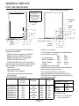
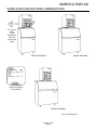
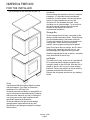
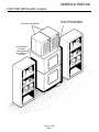
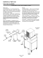
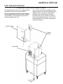
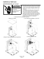
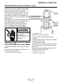
NME950 & FME1200
INTRODUCTION
To the owner or user: The service manual you are
reading is intended to provide you, and the
maintenance or service technician, with the
information needed to install, start up, clean,
maintain, and service this ice system.
This machine is a modular ice system that fits a
variety of Scotsman ice storage bins.
It features: front service for the freezer, gear
motor, control box, water reservoir, and bin control;
an electronic circuit for monitoring ice and water
level; a thermostatic expansion valve; and R-404A
as the refrigerant.
TABLE OF CONTENTS
FOR THE INSTALLER
. . . . . . . . . . . . . . . . . . . . . . . . . . . . . . . . . . .
Page 2
SAMPLE BIN AND MACHINE COMBINATIONS . . . . . . . . . . . . . . . . . . . . . .
Page 3
FOR THE INSTALLER
. . . . . . . . . . . . . . . . . . . . . . . . . . . . . . . . . . .
Page 4
FOR THE PLUMBER . . . . . . . . . . . . . . . . . . . . . . . . . . . . . . . . . . . .
Page 6
FOR THE ELECTRICIAN . . . . . . . . . . . . . . . . . . . . . . . . . . . . . . . . . .
Page 7
START UP
Page 9
. . . . . . . . . . . . . . . . . . . . . . . . . . . . . . . . . . . . . . . .
COMPONENT DESCRIPTION
. . . . . . . . . . . . . . . . . . . . . . . . . . . . . . .
COMPONENT DESCRIPTION: Control Box
Page 10
. . . . . . . . . . . . . . . . . . . . . . . .
Page 11
. . . . . . . . . . . . . . . . . . . . . . . . . . . . . . . .
Page 13
. . . . . . . . . . . . . . . . . . . . . . . . . . . . . . . . . . . .
Page 14
OPERATION: Refrigeration . . . . . . . . . . . . . . . . . . . . . . . . . . . . . . . . .
Page 15
OPERATION: Performance . . . . . . . . . . . . . . . . . . . . . . . . . . . . . . . . .
Page 15
SANITIZING AND CLEANING
Page 16
ELECTRICAL SEQUENCE:
OPERATION: Water
. . . . . . . . . . . . . . . . . . . . . . . . . . . . . . .
MAINTENANCE AND CLEANING
MAINTENANCE: Air Cooled
. . . . . . . . . . . . . . . . . . . . . . . . . . . . .
Page 17
. . . . . . . . . . . . . . . . . . . . . . . . . . . . . . . .
Page 18
MAINTENANCE AND CLEANING: Auger
SERVICE DIAGNOSIS:
. . . . . . . . . . . . . . . . . . . . . . . . .
Page 19
. . . . . . . . . . . . . . . . . . . . . . . . . . . . . . . . . .
Page 20
REMOVAL AND REPLACEMENT: Water Reservoir & Bin Controls
. . . . . . . . . . . .
Page 22
REMOVAL AND REPLACEMENT: Bearing And Breaker . . . . . . . . . . . . . . . . . .
Page 23
REMOVAL AND REPLACEMENT: Auger
. . . . . . . . . . . . . . . . . . . . . . . . .
Page 24
REMOVAL AND REPLACEMENT: Water Seal . . . . . . . . . . . . . . . . . . . . . . .
Page 25
REMOVAL AND REPLACEMENT: Evaporator . . . . . . . . . . . . . . . . . . . . . . .
Page 26
REMOVAL AND REPLACEMENT: Gearmotor . . . . . . . . . . . . . . . . . . . . . . .
Page 27
REMOVAL AND REPLACEMENT: Fans
. . . . . . . . . . . . . . . . . . . . . . . . . .
Page 28
REFRIGERATION SYSTEM SERVICE . . . . . . . . . . . . . . . . . . . . . . . . . . .
Page 29
LIQUID CHARGING
Page 30
. . . . . . . . . . . . . . . . . . . . . . . . . . . . . . . . . . . .
CIRCUIT BOARD TESTING:
. . . . . . . . . . . . . . . . . . . . . . . . . . . . . . . .
Parts lists and wiring diagrams are in the center of this manual, printed on yellow paper.
This manual was printed on recycled paper.
Keep it for future reference.
Note the warning symbol
where it appears. It marks a
possible hazard.
January 1995
Page 1
Page 31
NME950 & FME1200
FOR THE INSTALLER
BACK VIEW: AIR COOLED
BACK VIEW: WATER COOLED
Note: Allow 6"
behind and 6"
above either unit
for air circulation,
utility connections,
and service.
ELECTRICAL
INLET
ELECTRICAL
INLET
WATER
INLET
9.5"
5.25"
5.25"
7.3"
3"
3"
Condenser Inlet 3/8" FPT
WATER INLET
3/8" FLARE
2.9"
2.1"
DRAIN
3/4" FPT
Condenser Drain 1/2" FPT
3.4"
5.7"
DRAIN
3/4" FPT
4.9"
7.46"
This machine is designed to fit the following
Scotsman storage bins:
B90 and extensions (with bin top KBT18)
BH800 using bin top KBT15 (one unit).
BH800 (two units, no bin top required).
BH900 with KBT24 (one unit)
BH900 with KBT25 (two units side by side)
When installing a new system, check to be sure
that everything is on site before beginning:
Correct Bin
Correct Ice Machine
Correct Bin Top (if required)
All kits, legs, and information required for
the specific job.
SPECIFICATIONS : ICE MAKER
Model Number
FME1200AE-3A
FME1200WE-3A
FME1200AE-32A
FME1200WE-32A
NME950AE-3A
NME950WE-3A
NME950AE-32A
NME950WE-32A
Installation Limitations:
This ice system is designed to be installed indoors,
in a controlled environment:
Min
Max
Air Temperature
500F
1000F
Water Temperature
400F
1000F
Water Pressure
20 PSI
80 PSI
Voltage
-5%
+10%
(Compared to the nameplate)
Operating the machine outside of the limitations is
misuse and can void the warranty.
The normal finish for the ice machine is
enamel-sandalwood. A stainless steel panel kit,
SPKFM21 may be field installed to convert the unit
to a stainless steel finish.
Dimensions
(w/o bin)
WxDxH
Basic
Electrical
Ice Type
21" x 24" x 27"
same
same
same
same
same
same
same
208-230/60/3
same
208-230/60/1
same
208-230/60/3
same
208-230/60/1
same
FLAKE
same
same
same
Nugget
same
same
same
January 1995
Page 2
Condenser
Type
Air
Water
Air
Water
Air
Water
Air
Water
Refrigerant Charge*
Air Cooled 30 oz
R-404A
Water
24 oz
Cooled
R-404A
* Always go by the
nameplate charge.
Note: 50 Hz (-6) models have
also been produced.
9.43"
NME950 & FME1200
SAMPLE BIN AND MACHINE COMBINATIONS
Air Flow on
All Air
Cooled
Models is In
the Front
and Out the
Back
FME1200 ON BH550*
NME950 ON BH800*
The Nameplate is
located on the back
of the machine.
FME1200 ON BH900*
* Bin Top Kit Required
January 1995
Page 3
NME950 & FME1200
FOR THE INSTALLER
Typical Storage Bin with Extension and Bin Top
Location:
After uncrating and inspection, the unit is ready for
installation. It is important that the machine be
installed in a location where it has enough space
around it to be accessible for service, and
minimum of 6" be allowed at the back for air
circulation on air cooled models. Try to avoid hot,
dirty and crowded locations. Be sure that the
location for the machine is within the
environmental limitations.
Storage Bin:
Tip the storage bin on its back, using parts of the
carton to protect the exterior finish. Install the legs
into the threaded holes in the bottom of the bin.
Turn the leg levelers all the way in preparation for
leveling later. Return the bin to the upright
position, remove paper covering the bin gasket.
Note: Do not push bin into position, but lift it there.
Pushing a bin, especially one with ice in it, can
cause damage to the legs and the leg mounts.
Install the appropriate bin top on the bin, according
to the instructions for the bin top.
Ice Maker:
The machine is heavy, so the use of a mechanical
lift is recommended for lifting the machine high
enough to install on top of the bin. After the unit is
placed on the bin, line it up so it is even with the
back side. Secure the machine to the bin with the
hardware provided with the machine.
Remove the front panel and remove any shipping
blocks.
Scotsman Ice Systems are designed and
manufactured with the highest regard for safety
and performance. They meet or exceed the
standards of UL, NSF and CUL.
Scotsman assumes no liability or responsibility of
any kind for products manufactured by Scotsman
that have been altered in any way, including the
use of any part and/or other components not
specifically approved by Scotsman.
Scotsman reserves the right to make design
changes and/or improvements at any time.
Specifications and design are subject to change
without notice.
January 1995
Page 4
NME950 & FME1200
FOR THE INSTALLER: Location
DO NOT STACK ANYTHING IN
FRONT OF THE MACHINE(S)
TWO UNITS ON ONE BIN
ALLOW ROOM
FOR AIR
CIRCULATION
AND SERVICE
ACCESS
January 1995
Page 5
NME950 & FME1200
FOR THE PLUMBER
CONFORM TO ALL APPLICABLE CODES
Water Inlet
Drains
Air Cooled Models: The recommended water
supply is clean, cold water. Use 3/8" O.D. copper
tubing, connect to the 3/8" male flare at the back of
the cabinet. Install a hand valve near the machine
to control the water supply.
Water Treatment: In most areas, a water filter of
some type will be useful. In areas where the water
is highly concentrated with minerals the water
should be tested by a water treatment specialist,
and the recommendations of the specialist
regarding filtration and/or treatment should be
followed.
Water Cooled Models: A separate 3/8" O.D.
copper line is recommended, with a separate hand
valve to control it. It is connected to a 3/8" FPT
condenser inlet at the back of the cabinet. The
water pressure to all lines must always be above
20 psig, and below 80 psig.
Air Cooled Models: There is one 3/4" FPT drain
at the back of the cabinet, the drain line is of the
gravity type, and 1/4 inch per foot fall is an
acceptable pitch for the drain tubing. There should
be a vent at the highest point of the drain line, and
the ideal drain receptacle would be a trapped and
vented floor drain. Use only 3/4" rigid tubing.
Water Cooled Models : In addition to the above
mentioned drain, a separate condenser drain must
be installed. Connect it to the 1/2" condenser
drain connection at the back of the cabinet.
Storage Bin : A separate gravity type drain needs
to be run, similar to the air cooled drain. Insulation
of this drain line is recommended.
AIR COOLED
MODELS
WATER
COOLED
FIELD
SUPPLIED
FILTER
CONDENSER
INLET
VENTED
DRAIN
HAND
VALVE
HAND
VALVE
WATER
FILTER
CONDENSER
DRAIN
VENTED
DRAIN
WATER
INLET
January 1995
Page 6
NME950 & FME1200
FOR THE ELECTRICIAN
CONFORM TO ALL APPLICABLE CODES
The electrical power to the unit is supplied through
the junction box at the rear of the machine.
Check the nameplate (located on the back panel)
for the voltage requirements, and for the minimum
circuit ampacity. The machine requires a solid
chassis to earth ground wire.
The ice maker should be connected to its own
electrical circuit so it would be individually fused.
Voltage variation must remain within design
limitations, even under starting conditions.
All external wiring must conform to national,
state, and local electrical codes. The use of a
licensed electrician is required to perform the
electrical installation.
WATER COOLED
POWER
SUPPLY
AIR COOLED
January 1995
Page 7
NME950 & FME1200
FOR THE INSTALLER
Final Check List
1. Is the ice system installed indoors in a location
where the air and water temperatures are
controlled, and where they do not exceed the
design limitations?
5. Is there a minimum of 6" clearance at the back
of the machine for proper service access and air
circulation?
6. Is the water pressure a minimum of 20 psig?
2. Is there an electrical service disconnect within
sight of the installed machine? Has the voltage
been checked, and compared to nameplate
requirements?
3. Have all the plumbing connections been made
and checked for leaks?
4. Has the machine and bin been leveled?
7. Has the machine been secured to the bin?
8. Is there clearance over the top of the machine
for service access?
9. Is there a water shut off valve installed near the
machine?
10. Have all of the shipping blocks been removed?
January 1995
Page 8
NME950 & FME1200
START UP
Pre-Start Inspection
1. Remove the front and side service panels.
2. Check that the styrofoam shipping blocks have
been removed.
3. Inspect the interior of the machine for loose
screws or wires. Check that no refrigerant lines
are rubbing each other. Check that the fan blade
turns freely (air cooled).
4. Check that the unit is installed correctly
according to the final check list (page 8).
Start Up
1. Go through the prestart inspection.
2. Open the hand valve, observe that water enters
the water reservoir, fills the tube from the reservoir
to the evaporator, and then shuts off. Check for
leaks.
3. Switch the master switch on.
The electrical start up sequence is now on
automatic.
A. There should be a short (15 second) delay
before the gear motor starts.
B. After the gear motor starts, the compressor will
start.
4. On air cooled models, the condenser will begin
to discharge warm air, on water cooled models,
the water regulating valve will open, and warm
water will be discharged into the drain.
5. The unit should soon be making ice, if desired,
the low side pressure may be checked: it should
be 32 psig + or - 2 psig.
The suction line temperature at the compressor is
normally very cold, nearly to the point of frost up to
the compressor body, but not on it.
The air cooled discharge pressure will depend
upon air and water temperatures, but should be
between 200 psig and 280 psig.
The water cooled discharge pressure should be
constant at about 245 psig.
The above numbers are for new, clean machines,
you can expect to see some values higher, and
some lower between different units.
6. THERE ARE NO ADJUSTMENTS TO MAKE ,
so replace the panels.
7. Clean and/or sanitize the storage bin interior,
wipe off the exterior with a clean, damp cloth.
8. Give the owner/user the service manual, instruct
him/her in the operation of the unit, and make sure
they know who to call for service.
9. Fill out the manufacturers registration card, and
mail it to the Scotsman Factory.
10. Fill out the warranty registration form, and mail
it to Scotsman.
January 1995
Page 9
NME950 & FME1200
COMPONENT DESCRIPTION
Control Box: Contains the electrical controls that
operate the machine.
High Pressure Cut Out Switch : A manual reset
switch sensing the high side refrigeration pressure.
It is set to shut the machine off if the discharge
pressure should ever exceed 450 psig.
Evaporator: A vertical stainless steel tube,
refrigerated, and water filled. In it there is a
stainless steel auger.
Compressor: The refrigerant vapor pump.
Reservoir: Float operated, it maintains the water
level in the evaporator at a constant level, it also
contains the water level sensor.
Water Level Sensor: Senses if there is water in
the reservoir to make ice out of. Will shut the
machine off it there is none.
Ice Discharge Chute : Directs the ice produced
by the evaporator into the storage bin.
Ice Level Sensor: An electronic "eye", it senses
the presence of ice in the bottom of the ice
discharge chute. Operates to turn the ice machine
on and off automatically as the level of ice in the
bin changes.
Gear Motor: An oil filled, speed reduction
gearbox, driving the auger.
Drain Tube : When uncapped and lowered, drains
the evaporator.
Condenser: Air or water cooled, where the heat
removed in ice making is discharged.
Expansion valve : The refrigerant metering
device.
AIR COOLED
CONTROL BOX
RESERVOIR
CONDENSER
EXPANSION
VALVE
Hi Pressure
Cut Out
DRAIN
TUBE
ICE CHUTE
COMPRESSOR
January 1995
Page 10
ICE LEVEL
SENSORS
NME950 & FME1200
COMPONENT DESCRIPTION: Control Box
Contactor: A definite purpose contactor
connecting the compressor and the fan motor to
the power supply.
Circuit Board: Controls the operation of the ice
machine using input from sensors and pressure
controls. Switches loads on and off thru relays.
Transformer: Supplies low voltage to the circuit
board.
Low Pressure Cut Out Switch: A manual reset
control that shuts off the ice machine when the low
side pressure drops below a preset point, 0-4 psig.
Potential Relay : The compressor start relay.
On/Off Switch: Manual control for the machine.
Control Box
ON/OFF SWITCH
LOW
PRESSURE
CUT OUT
SWITCH
POTENTIAL
RELAY
CONTACTOR
"No Water " light,
glows when there is
not enough water in
the reservoir
TRANSFORMER
CIRCUIT
BOARD
"Bin Empty" light,
glows when ice level is
below electric eyes.
January 1995
Page 11
NME950 & FME1200
COMPONENT DESCRIPTION
Evaporator : A refrigerated vertical tube filled with
water and containing a water seal and auger.
Auger: A solid stainless steel double spiral auger,
it pushes the ice crystals up to the top of the
evaporator.
Water Seal: A two part "face" seal, the top half
rotating with the auger, the bottom half stationary,
the sealing action being where the two seal "faces"
meet.
Ice Sweep : A plastic cap with "fingers". It revolves
with the auger to "sweep" the ice into the ice chute.
Breaker (Divider): Where the ice is compressed
and much of the extra water is squeezed out of it
before it is discharged into the bin.
Motor: A split phase motor that drives the gear
reducer.
Thrust Bearing: As the ice is pushed up the
evaporator, the auger is thrust down, and pressure
from the auger thrust is taken up by this bearing.
ICE SWEEP
BEARING
BREAKER/DIVIDER
AUGER
EVAPORATOR
WATER
SEAL
MOTOR
January 1995
Page 12
NME950 & FME1200
ELECTRICAL SEQUENCE:
Refer the wiring diagram as needed.
Shut Down consists of:
• The compressor relay opens.
If the machine is switched off at the master switch,
but is otherwise ready to go, switching the master
switch to on does the following:
• The bin empty light on the circuit board goes on
• There is a 15 second delay
• If there is enough water in the reservoir, the
circuit board will allow the machine to start up.
Start up consists of:
• The compressor relay and auger motor relay
become energized, connecting power to the
windings of the auger motor.
• The auger motor starts, and the centrifugal
switch closes, connecting power to the
compressor contactor coil.
• The contactor is energized, connecting power
to the compressor, and the compressor starts.
• As ice goes past the ice level sensors, the bin
empty light will stay on, and the machine will
continue to run, unless the ice stays between
the sensors for more than 15 seconds (bin full).
At that point, the bin empty light goes out, and
the machine shuts down.
• The compressor contactor opens
• The compressor stops
• The auger motor is run by the circuit board for 2
more minutes, clearing out ice in the
evaporator, and then
• The auger motor relay opens, and the auger
motor stops.
If the ice level sensor is clear (bin empty) for more
than 15 seconds, the machine will start up again.
Another purpose of the circuit board is to turn the
machine off if there is not enough water in the
machine.
• When the water level in the reservoir falls
below the water level sensor, the machine will
"shut down"
• When the water refills the reservoir, the
machine will start up again.
Separate from the circuit board:
• If the high pressure control (cut out switch)
opens, the machine will stop immediately
(through the relays on the circuit board). it is a
manual reset.
• If the low pressure control (cut out switch)
opens, the machine will stop immediately
(through the relays on the circuit board). It is a
manual reset.
• The master switch is the manual control for the
complete machine, but it is not a service
disconnect.
January 1995
Page 13
NME950 & FME1200
OPERATION: Water
Water enters the machine through the 3/8" male
flare at the rear of the cabinet, goes to a strainer
and then to the water reservoir which it enters
through the float valve. The water then goes out
the bottom of the reservoir tank to the bottom of
the evaporator.
Reservoir overflow or evaporator condensation is
routed to the drain. Water cooled models have a
separate water circuit for the cooling water: it
enters the fitting at the rear, goes to the water
regulating valve, then to the water cooled
condenser and down the drain.
WATER INLET
WATER
LEVEL
RESERVOIR
EVAPORATOR
STRAINER
DRAIN
ICE
CHUTE
EVAPORATOR
DRAIN
EVAPORATOR INLET
WATER SCHEMATIC
January 1995
Page 14
NME950 & FME1200
OPERATION: Refrigeration
Beginning at the compressor, the refrigerant is
compressed into a high temperature gas. The
discharge line directs this gas to the condenser.
At the condenser (air or water cooled) the gas is
cooled by either air or water and it then condenses
into a liquid. This high pressure liquid then goes
through the liquid line to the expansion valve.
The thermostatic expansion valve meters liquid
refrigerant into the evaporator, the volume of liquid
refrigerant depending upon the temperature of the
evaporator; warmer evaporators get more
refrigerant and colder evaporators get less.
At the evaporator, the refrigerant enters an area of
relatively low pressure, where it can easily "boil
off" or evaporate. As it evaporates, it absorbs heat
from the evaporator and whatever is in contact
with it (such as the water inside it). After the
evaporator, the refrigerant, now a low pressure
vapor, goes through the suction line back to
compressor, where the cycle is repeated.
Refrigeration Schematic
CONDENSER
LIQUID
LINE
SUCTION LINE
DISCHARGE
LINE
EVAPORATOR
FAN
MOTOR
THERMOSTATIC
EXPANSION
VALVE
COMPRESSOR
GEAR
MOTOR
OPERATION: Performance
Typical Low Side Pressure
• Air Cooled: 34 - 38 PSIG
• Water Cooled: 32 PSIG
Typical Discharge Pressure
• Air Cooled: 220 - 275 PSIG
• Water Cooled: 245 PSIG
Typical Compressor Amp Draw
• Single phase = 4.3
• Three phase =
Low Pressure Cut Out
• 0 - 4 PSIG
Refrigerant Charge
• Air Cooled: 30 ounces HP62
• Water Cooled: 24 ounces of HP62.
2.8
Superheat
• 5 - 7 degrees
High Pressure Cut Out
• 450 PSIG
January 1995
Page 15
NME950 & FME1200
SANITIZING AND CLEANING
A Scotsman Ice System represents a sizable investment of time and money in any company’s business. In
order to receive the best return for that investment, it MUST receive periodic maintenance.
It is the USER’S RESPONSIBILITY to see that the unit is properly maintained. It is always preferable, and
less costly in the long run, to avoid possible down time by keeping it clean; adjusting it as needed; and by
replacing worn parts before they can cause failure. The following is a list of recommended maintenance
that will help keep the machine running with a minimum of problems.
Maintenance and Cleaning should be scheduled at a minimum of twice per year.
ICE MAKING SYSTEM: In place cleaning
1. Check and clean any water treatment devices,
if any are installed.
2. Remove screws, and the front and top panels.
3. Move the ON-OFF switch to OFF.
4. Remove all the ice from the storage bin.
5. Remove the cover to the water reservoir and
block the float up.
6. Drain the water reservoir and freezer assembly
using the drain tube attached to the freezer water
inlet. Return the drain tube to its normal upright
position and replace the end cap.
7. Prepare the cleaning solution: Mix eight
ounces of Scotsman Ice Machine Cleaner with
three quarts of hot water. The water should be
between 90-115 degrees F.
Scotsman Ice Machine
Cleaner contains acids.
These compounds may
cause burns.
If swallowed, DO NOT
induce vomiting. Give large
amounts of water or milk.
Call Physician immediately.
In case of external contact,
flush with water.
Keep out of the reach of
children.
8. Slowly pour the cleaning solution into the water
reservoir until it is full. Wait 15 minutes, then
switch the master switch to ON.
9. As the ice maker begins to use water from the
reservoir, continue to add more cleaning solution
to maintain a full reservoir.
10. After all of the cleaning solution has been
added to the reservoir, and the reservoir is nearly
empty, switch the master switch to OFF.
11. After draining the reservoir, as in step 6, wash
and rinse the water reservoir.
12. Go thru steps 13-18 to sanitize the ice machine
water system.
13. Mix two gallons of sanitizer solution. Use an
approved sanitizer.
A possible sanitizer solution may be obtained by
mixing two gallons of warm (90-115oF.) potable
water with 1 ounce of household bleach.
14. Slowly pour the sanitizer solution into the water
reservoir until the float rises, then switch the
master switch ON.
15. As the ice machine uses water from the
reservoir, continue to pour the sanitizer solution
into the reservoir.
16. After 1⁄2 of the sanitizer solution has been
added to the reservoir, and the reservoir is nearly
empty, switch the master switch OFF.
17. Drain the reservoir and thoroughly wash the
interior of the reservoir and cover with sanitizer
solution.
18. Remove the block from the float in the water
reservoir.
19. Switch the master switch to ON
20. Continue ice making for at least 15 minutes, to
flush out any cleaning solution. Switch the master
switch OFF.
DO NOT USE any ice produced from the
cleaning solution.
Be sure no ice remains in the bin.
21. Remove all ice from the storage bin.
22. Add warm water to the ice storage bin and
thoroughly wash and rinse all surfaces within the
bin.
23. Sanitize the bin interior by thoroughly washing
the interior of the bin and bin door with the balance
of the sanitizer solution.
24. Switch the master switch ON.
25. Replace the panels.
January 1996
Page 16
NME950 & FME1200
MAINTENANCE AND CLEANING
A. Check the bearing by:
• removing the ice chute cover
Electrical shock hazard.
Electrical shock can cause
personal injury.
Disconnect power before
beginning to service
components.
1. The bin control uses devices that sense light,
therefore they must be kept clean enough so that
they can ‘‘see’’. At least twice a year, remove the
bin control sensors from the base of the ice chute,
and wipe the inside clean, as illustrated.
2. The ice machine senses water level by a probe
located in the water reservoir. At least twice a
year, the probe should be removed from the
reservoir, and the tip wiped clean of mineral
build-up.
• unscrewing the ice sweep
• removing the water shed
• unscrewing the breaker cover.
• unscrewing the auger stud
Inspect the assembly, looking for wear.
ICE LEVEL SENSORS:
SLIDE TO REMOVE
PULL UP TO
REMOVE PROBE
CLEAN THE
LIGHT SENSORS
RESERVOIR
See Removal and Replacement to replace
bearing or seals. Reverse to reassemble.
4. Check and tighten all bolts and screws.
CLEAN THE
WATER LEVEL
PROBE
ICE SWEEP
///////////////////////////////////////////
CAUTION: THE TIP IS
MADE OF GLASS
//////////////////////////////////////////
BREAKER
COVER
3. The bearing in the breaker should also be
checked at least two times per year .
January 1995
Page 17
NME950 & FME1200
MAINTENANCE: Air Cooled
Electrical shock hazard.
Electrical shock can cause
personal injury.
Disconnect power before
beginning to service
components.
5. Clean the air cooled condenser.
The air flow on this model is from front to back, so
the inside of the machine will have to be available
to clean the air cooled condenser. Use a vacuum
cleaner or coil cleaner if needed. Do NOT use a
wire brush.
A. Disconnect electrical power, and remove the
filter. The filter may be cleaned or replaced.
B. Clean the condenser: the condenser may
appear to be clean on the surface, but it can still
be clogged internally. Check with a flash light from
the front to see if light can be seen though the
condenser fins. Reverse to reassemble.
TO GAIN ACCESS TO CONDENSER SURFACE:
3. PULL FAN MOTOR ASSEMBLY UP AND OUT
1. REMOVE TOP PANEL
2. REMOVE TWO SCREWS & UNPLUG FAN MOTORS.
January 1995
Page 18
4. CLEAN CONDENSER FINS.
NME950 & FME1200
MAINTENANCE AND CLEANING: Auger
In some areas, the water supply to the ice maker
will contain a high concentration of minerals, and
that will result in an evaporator and auger
becoming coated with these minerals, requiring a
more frequent removal than twice per year. If in
doubt about the condition of the evaporator and
auger, the auger can be removed so the parts can The auger has sharp
edges, handle with care.
be inspected.
Note: Water filters can filter out suspended solids,
but not dissolved solids. ‘‘Soft’’ water may not be
the complete answer. Check with a water
treatment specialist regarding water treatment.
For more information on removal of these
parts, see REMOVAL AND REPLACEMENT.
Electrical shock hazard.
Electrical shock can cause
personal injury.
Disconnect power before
beginning to service
components.
Turn off the water supply.
1. To remove the auger, remove the front and top
panels.
2. Push back bail clamp holding ice chute cover to
ice chute, and remove cover.
3. Unscrew and remove ice sweep.
ALLEN
SCREWS
BREAKER &
BEARING &
AUGER
ASSEMBLY
4. Loosen band clamp under ice chute, and
remove ice chute from evaporator.
5. Remove 4 allen screws holding breaker to
evaporator.
6. Drain the evaporator by lowering and uncapping
the evaporator drain hose.
7. Pull up to remove auger.
After the auger has been removed, allow the auger
to dry: if the auger is not bright and shiny, it must
be cleaned.
Clean the auger and evaporator as required. DO
NOT HONE THE EVAPORATOR.
8. Replace the water seal.
9. Reverse to reassemble.
January 1995
Page 19
NME950 & FME1200
SERVICE DIAGNOSIS:
Symptom
No ice is made, nothing
operates
Possible Cause
Unit off due to no power
Unit off due to master switch in
OFF position.
Unit off due to low water level.
Unit off due to ice level
sensors (photo-electric eyes)
blocked.
Unit off due to scale on water
level sensor.
Unit off due to high pressure
control open.
Auger motor does not turn.
Low pressure control open
No ice, auger motor is turning
Centrifugal switch in auger
motor does not close.
No power to circuit board,
transformer is open.
Circuit Board gear motor relay
will not close
Water level or ice level sensor
failed.
Compressor contactor coil is
open
Compressor will not start
Probable Correction
Restore Power
Switch master switch to ON.
Check water supply, filter,
strainer, float valve. Correct
water supply.
Check/clean ice level sensors.
Clean water level sensor.
Check for water interruption
(water cooled) or fan motor
failure (air cooled).
Winding open, bearings
seized. Check/replace auger
motor.
Check that auger turns
Check charge.
Check for a restricted system
Check/replace centrifugal
switch.
Replace transformer.
Check, replace board
Check, replace sensor
Check/replace contactor
Check start capacitor.
Check start relay
Check compressor windings
Circuit board compressor relay Check, replace board
will not close.
Unit makes ice, but very slowly. High discharge pressure
Clean the air filter and
because of a dirty condenser
condenser.
Low capacity because the
Clean the water system
auger and evaporator are
coated with mineral scale
Low suction pressure due to
Locate leak. Recover
low refrigerant charge
refrigerant, repair leak, replace
dryer, evacuate and weigh in
the nameplate charge
January 1995
Page 20
NME950 & FME1200
SERVICE DIAGNOSIS
Symptom
Water Leak
Possible Cause
Drain plugged up
Tubing cracked
Condensation on drain tubing
Hose off
Reservoir cover off
Reservoir cracked
Evaporator water seal leaks
Excessive water use
Water cooled model, water
regulating valve not adjusted
properly.
Reservoir float valve leaks thru
Water cooled model,
overcharged with refrigerant
Water cooled model,
condenser coated with minerals
Excessive ice meltage
Bin drain clogged
Improper installation of drains,
they are connected.
Poor fit between bin door and
door frame
Machine makes too much noise Evaporator coated internally
with minerals
Motor bearings dry
January 1995
Page 21
Probable Correction
Clean out drain
Replace tubing
Insulate tubing
Reattach hose
Return cover to reservoir
Replace reservoir
Check base of evaporator &
drip pan. If the seal leaks, shut
off the water, remove the
auger, replace the water seal.
Check gear motor for water
infiltration.
Adjust to 245 PSIG discharge
pressure
Replace float valve or seat
Recover and weigh refrigerant.
Weigh in correct charge.
Acid clean water cooled
condenser.
Clean out bin drain.
Drains must be separate.
Adjust or replace
Clean with Scotsman Ice
Machine Cleaner
Oil or replace motor
NME950 & FME1200
REMOVAL AND REPLACEMENT: Water Reservoir & Bin Controls
WATER RESERVOIR
1. Shut off the water supply to the ice maker.
2. Remove front panel.
3. Remove reservoir cover.
4. Disconnect water inlet tube from reservoir inlet
fitting.
5. To remove float valve, push in "locking tabs" as
shown and pull float up.
Note: The plunger/seat is available separately as
a part.
6. To remove reservoir, pull up and remove water
sensor.
8. Disconnect water outlet tubes.
9. Remove mounting screws from reservoir
bracket, and remove reservoir from ice maker.
10. Reverse to reassemble.
FLOAT
ASSEMBLY
PLUNGER
/SEAT
LOCKING
TABS
ICE
CHUTE
SLIDE BIN
CONTROLS IN
AND OUT
BIN CONTROLS (Ice Level Sensors)
1. Disconnect electrical power.
2. Remove front panel.
3. Remove control box cover.
4. Locate ice chute, at the base of the chute, in
front of and behind it are two plastic bin control
mounts.
5. Slide each bin control to the left, and in the
control box, disconnect the electrical leads
connecting the bin control to the circuit board.
6. Reverse to reassemble, be certain that the bin
controls are aligned so that the ice level sensors
are visible (centered) through the holes in the ice
chute.
January 1995
Page 22
NME950 & FME1200
REMOVAL AND REPLACEMENT: Bearing And Breaker
Note: Removal of the auger, water seal,
evaporator and gear motor must begin at the top
of the assembly.
1. Remove panels and disconnect electrical
power.
Electrical shock hazard.
Electrical shock can cause
personal injury.
Disconnect power before
beginning to service
components.
2. Push back bail clamp and remove ice chute
cover.
3. Unscrew and remove ice sweep.
4. Remove insulation halves from outside of ice
chute, loosen band clamp under ice chute, lift up
and remove ice chute.
5. The breaker may be removed from the auger
and evaporator without disturbing the auger.
a. Unscrew breaker cover from breaker (left hand
threads)
b. Unscrew auger stud from top of auger.
Step 5-a
c. Unscrew 4 allen head cap screws holding
breaker to evaporator.
d. Lift up, and remove breaker/bearing assembly
from auger & evaporator.
6. Service the bearing. Check for rust, rough spots
and damage.
a. The bearing is pressed into the breaker, to
remove the bearing and replace it an arbor press
is needed.
b. Replace lower seals before installing new
bearing in breaker.
Note: seals must be pressed in with a tool pushing
against the outer edge only, they will not install by
hand.
Replace parts as required. Re-grease bearing with
Scotsman part no. A29123-001 bearing grease.
Replace top seal, and check the o-rings, replace if
cut or torn.
7. Reverse to reassemble: specific tools and
materials are required to install properly.
a. Add food grade grease such as Scotsman part
number 19-0569-01 to the seal area before
installing on the auger.
b. Check the seal to shaft areas for cuts, or rough
spots: none are permitted.
Note: Flaker parts are shown in this manual.
Nugget Breakers do NOT have a Slotted Collar.
Step 5-b
Step 5-c and Step 6
BEARING
ICE
SWEEP
SEALS
AUGER
STUD
BREAKER
COVER
January 1995
Page 23
SLOTTED
COLLAR
NME950 & FME1200
REMOVAL AND REPLACEMENT: Auger
To Remove the Auger:
Turn off the water to the machine, and unclip the
evaporator drain hose, pull it down and drain the
evaporator into the bin or a container.
1. The top panel must be removed.
Electrical shock hazard.
Electrical shock can
cause personal injury.
Disconnect power before
beginning to service
components.
2. Remove ice chute cover.
3. Unscrew ice sweep.
4. Loosen band clamp and remove ice chute body.
5. The auger and breaker/bearing may now be
removed as an assembly.
a. Unscrew 4 allen head cap screws holding
BREAKER
AND AUGER
ASSEMBLY
a. Unscrew breaker cover from breaker (left hand
threads)
b. Unscrew auger stud from top of auger.
c. Unscrew 4 allen head cap screws holding
breaker to evaporator.
d. Lift up & remove breaker from evaporator.
e. If the auger is stuck use a slide hammer type
puller to pull on the auger at the threaded hole.
The size of that hole is 5/8"-18.
Inspect the auger, the critical areas of the auger
are:
1. The auger body. It should be clean and
shining. Sometimes an auger will appear clean
when wet, but after it is dry it will be seen to be
stained. Scrub the auger with ice machine cleaner
and hot water.
WARNING
Ice machine cleaner is an acid. Handle it with
extreme care, keep out of the reach of children.
2. The water seal area. Because the auger has
been removed, the water seal will have to be
replaced. Remove the water seal top half from the
auger, and inspect the auger for minerals, clean as
required.
WARNING
The auger has sharp
edges, handle with care.
SLIDE HAMMER
PULLER
THREAD INTO THE
AUGER HERE
breaker to evaporator.
b. Lift up on breaker and remove auger from
evaporator.
Note: If the auger is stuck, the breaker must
be removed from the auger.
The breaker may be removed from the auger and
evaporator without disturbing the auger.
January 1995
Page 24
NME950 & FME1200
REMOVAL AND REPLACEMENT: Water Seal
To Remove the Water Seal:
(Assuming all steps to remove the auger have
been performed.)
1. The gear motor/evaporator assembly will have
to be exposed.
2. Remove the 4 hex head cap screws holding the
evaporator to the gear motor assembly. Lift the
evaporator up and off of the gear motor.
3. Remove the snap ring or wire retainer from the
grove under the water seal.
4. Pull or drive out the lower half of the water seal.
To Replace the Water Seal:
1. Lubricate the water seal with water, and push
the water seal into the bottom of the evaporator
slightly past the grove for the snap ring.
2. Replace the snap ring and pull the water seal
down against it.
3. The part of the water seal that rotates with the
auger must also be replaced. Remove the old part
from the auger and clean the mounting area.
4. Place a small bead of food grade silastic sealant
(such as 732 RTV or Scotsman part number
19-0529-01) on the area of the auger where the
water seal is to be mounted.
REPLACING THE WATER SEAL
REMOVAL OF THE WATER SEAL
PLACE FOOD
GRADE SEALANT
HERE
WATER SEAL
RETAINING
RING
5. Carefully push the water seal (rubber side
against the auger shoulder and the silastic.)
CAUTION
Do not get any silastic onto the face of the seal.
6. Allow the auger and seal to air dry until the
silastic is dry on the surface.
7. If the original water seal was leaking, it would be
a good idea to inspect the interior of the gear
motor.
January 1995
Page 25
NME950 & FME1200
REMOVAL AND REPLACEMENT: Evaporator
Electrical shock hazard.
Electrical shock can cause
personal injury.
Disconnect power before
beginning to service
components.
To Replace the Evaporator:
(Assuming all the steps for removal of the thrust
bearing, breaker, auger, and water seal have been
performed.)
1. Discharge the refrigerant from the ice maker.
2. Unsweat the refrigerant connections:
a) At the thermostatic expansion valve outlet.
CAUTION
Heat sink the TXV body when unsweating or
resweating the adjacent tubing.
To Reassemble the Evaporator and Auger
1. After the gear motor has been inspected, fasten
the evaporator to the gear motor. Torque the bolts
to 110 inch pounds.
2. Lower the auger into the evaporator barrel,
slightly turning it to match up with the drive end.
Do Not Drop Into the Evaporator.
3. Complete the reassembly by reversing the
disassembly for the breaker & thrust bearing
assembly.
ICE SWEEP
b) At the suction line at the joint
about 3" from the evaporator.
3. Remove the evaporator.
4. Unsweat the drier from the liquid
line.
5. After installing a new water seal
in the new evaporator (see "To
Replace the Water Seal") sweat in
the new evaporator at the old tubing ICE CHUTE
connections.
6. Install an new drier in the liquid
line.
7. Evacuate the system until
dehydrated, then weigh in the
nameplate charge. Check for leaks.
8. Install auger, breaker, breaker
bearing assembly, and ice
discharge chute in reverse order of
disassembly.
AUGER
EVAPORATOR
BEARING
BREAKER/DIVIDER
January 1995
Page 26
NME950 & FME1200
REMOVAL AND REPLACEMENT: Gearmotor
Electrical shock hazard.
Electrical shock can cause
personal injury.
Disconnect power before
beginning to service
components.
To Remove and Repair the Gear motor
Assembly:
(Assuming that the procedures through removal of
the water seal have been performed.)
1. Remove the electrical wires from the gear drive
motor.
2. Unscrew the 4 cap screws holding the gear
motor to the base of the machine.
3. Remove the gear motor from the ice maker.
Bench test the gear motor, check for oil leaks,
noise, and amp draw.
To Inspect the gear motor.
A) Remove the cap screws holding the gear motor
case halves together and pry the two cases apart.
B) To lift off the cover, lift up until you can feel
internal contact, then pull the cover towards the
output gear end, and then lift the cover (with drive
motor attached) up and away from the gear motor
case.
Note: The gearcase cover, output gear,
bearings and output shaft are a pressed
together assembly.
C) Inspect the oil gears and bearings. If there is
evidence of water in the oil (rusty metal, too much
oil, white oil) replace the oil and damaged parts.
The oil charge is 14 oz. Do not overfill.
Reassemble and bench test the gear motor, check
for oil leaks, noise, and amp draw.
WATER SHED
CENTRIFUGAL
SWITCH
AUGER DRIVE MOTOR
COVER &
OUTPUT GEAR
ASSEMBLY
ROTOR BEARING
SEAL
January 1995
Page 27
NME950 & FME1200
REMOVAL AND REPLACEMENT: Fans
Electrical shock hazard.
Electrical shock can cause
personal injury.
Disconnect power before
beginning to service
components.
To Remove the Condenser Fan Motor
Assembly
1. Remove top panel.
2. Unplug the two fan motor wire leads from the
fan motors.
3. Remove the two hex head bolts from the top
end of the fan motor assembly.
4. Lift up and pull out the fan motor assembly.
5. Repair as needed.
6. To reassemble: Place the fan motor assembly
lower flange holes over the two allen head cap
screws in the base, and reinstall the hex head
bolts at the top of the assembly. Plug the fan
motors back in, and replace the top panel.
January 1995
Page 28
NME950 & FME1200
REFRIGERATION SYSTEM SERVICE
General:
Pressure-Temperature Chart for HP62
This ice machine uses R-404A refrigerant and polyolester oil. Do NOT
use mineral oil in this refrigeration system.
• R-404A is a "Near Azeotrope" so liquid charging is required:
• When the system is serviced, a special liquid line drier is required. It is
included with replacement compressors.
• HP62 is not compatible with mineral oil, so these ice machines use
Polyolester oil. Polyolester oil absorbs water very easily. When one of
these refrigeration systems is opened for service, it must be re-sealed
as soon as possible (15 minutes maximum).
• Special leak detection equipment is required to locate small refrigerant
leaks. Usually a leak detector capable of detecting a Halongenated
refrigerant or HFC-134a will work. Check with the leak detector
manufacturer if in doubt.
Access Valves: To use the access valves:
• Remove the cap from the stem, use a 3/16" allen wrench to check
that the valve is CLOSED. The remove the core cap.
• Close the valve and replace the caps when the job is finished.
The valve must be closed and the caps must be on or the valve
will leak.
ALLEN
WRENCH
Torque to
6-8 ft. lb..
Cap, Torque
to 8-12 ft. lb..
ACCESS VALVE
Cap, Torque
to 7-11 ft. lb..
January 1995
Page 29
VAPOR
VAPOR
TEMP. PRESS. TEMP. PRESS.
(DEG F) (PSIG) DEG F) (PSIG)
-20
17
70
146
-18
18
72
150
-16
20
74
155
-14
21
76
161
-12
23
78
166
-10
24
80
171
-8
26
82
177
-6
28
84
182
-4
29
86
188
-2
31
88
194
0
33
90
200
2
35
92
206
4
37
94
212
6
39
96
219
8
41
98
225
10
43
100
232
12
46
102
239
14
48
104
246
16
50
106
253
18
53
108
260
20
55
110
268
22
58
112
275
24
60
114
283
26
63
116
291
28
66
118
299
30
69
120
307
32
72
122
316
34
75
124
324
36
78
126
333
38
81
128
342
40
85
130
351
42
88
132
360
44
91
134
370
46
95
136
379
48
99
138
389
50
102
140
399
52
106
142
409
54
110
144
420
56
114
146
430
58
118
148
441
60
123
150
452
62
127
152
464
64
132
154
475
66
136
156
487
68
141
158
499
NME950 & FME1200
LIQUID CHARGING
Instructions for R-404A
In preparation for charging, the low side hose
should have a sight glass, and/or a restrictor
device (such as a "Charge Faster") installed in it
for metering liquid into the low side of the system.
1. After a thorough evacuation to at least 200
microns, shut off the manifold valves and switch
off the vacuum pump.
2. Place a drum of R-404A onto an electronic
scale.
Manifold Valve
Manifold Valve
3. Attach the charging hose to the drum.
4. Open the valve on the drum and purge the
charging hose.
Refrigerant Drum Valve
5. Zero out the scale.
Sight Glass
6. Shut the low side access valve at the ice
Low Side
Access Valve
machine.
7. Open the discharge manifold valve full open.
8. Watch the scale, when the correct charge is
shown, shut the manifold valve.
Note: If all of the charge will not "go in" the
discharge side:
A. Shut the discharge access valve at the ice
machine.
B. Switch the machine on.
C. Open the low side access valve at the ice
High Side
SCALE
Access Valve
machine.
D. Open the low side manifold valve and observe
the sight glass to be certain that only gas is
flowing into the system.
Hose Connection Schematic for Liquid Charging
E. When the proper charge is indicated on the
scale, shut off the manifold valve(s).
9. Shut off the valve on the refrigerant drum.
10. Re-open the manifold valves until all liquid has
flowed out of the hoses.
11. Shut the low side access valve on the ice
machine.
12. Remove hoses from ice machine and replace
all caps.
January 1995
Page 30
NME950 & FME1200
CIRCUIT BOARD TESTING:
These procedures require the machine to be connected to the power supply. The voltages of the
electronic circuit are very low, but HIGHER VOLTAGES ARE PRESENT IN THE UNIT. Do not touch
anything but the tester while the unit is being checked out. Make all connections to the circuit board with
the ELECTRICAL POWER OFF.
INSTRUCTIONS FOR USING TESTER (Optional, order part no. A33942-001)
(These instructions assume that the unit will not run, and prior investigation of electric power, controls,
and mechanical parts indicates that the electronic circuit may be at fault.)
If the "Reset" indicator (located in the "reset" switch) is off and the "NO WATER" indicator is lit, but
inspection shows that the water level in the reservoir is above the top of the water level sensor, OR the
"BIN EMPTY" indicator is off while inspection shows that the ice level sensors are properly aligned, clean
and not obstructed, use the tester as follows:
Bin Control Note: All testing is done with the
b. If the light on the tester IS on, move the ‘‘bin
electrical power on, the master switch on, and all
full’’ switch to Bin Empty. The light on the tester
reset switches ‘‘reset’’.
should go OFF, and the Bin Empty light on the
circuit board should go ON.
1. Unplug ‘‘photo trans’’ and ‘‘LED’’ connectors from
If the Bin Empty light is ON, wait 10-20 seconds for
the circuit board.
the machine to start, if the machine starts, replace
2. Plug ‘‘photo trans’’ and ‘‘LED’’ connectors from
the ice level sensors.
the tester into the circuit board.
If the Bin Empty light does not come ON, the
a. Move the ‘‘bin full’’ switch on the tester to Full.
circuit board should be replaced.
The light on the tester should be ON.
If the light on the tester is not on, the circuit board
should be replaced.
PHOTO TRANS
LIGHT GOES
ON
LED
LIGHT
GOES OFF
LIGHT GOES
ON
SWITCH TO
‘‘FULL ’’
SWITCH TO
‘‘BIN EMPTY ’’
January 1995
Page 31
NME950 & FME1200
CIRCUIT BOARD TESTING:
Water Level
1. Unplug ‘‘water sen’’ connector from control
board.
2. Plug ‘‘water sen’’ connector from Scotsman
tester into circuit board.
a. Move ‘‘water’’ switch on tester to No Water
position. The No Water light on the circuit board
should go ON. If not, replace the circuit board.
b. Move the ‘‘water’’ switch on the tester to the
Water position. The No Water light on the board
should go OFF. If not replace the circuit board. If
the light does go off, replace the water level sensor.
If the Bin Empty light is ON, wait 10-20 seconds for
the machine to start. The machine should start.
LIGHT OFF
LIGHT ON
WATER SENS
SWITCH TO
‘‘WATER ’’
SWITCH TO
‘‘NO WATER ’’
January 1995
Page 32