1
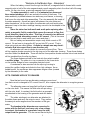
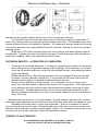
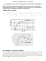
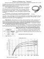
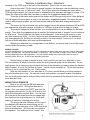
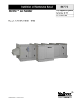
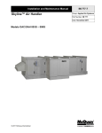
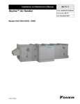
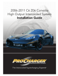
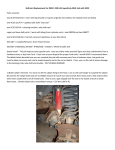
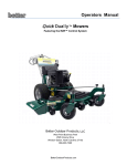
“Welcome to the Modern Age....Alternators”
ALTERNATORS
With the addition of more and more electrical accessories, the car manufacturers of the early
1960’s again found themselves in much the same spot as in the mid 1950’s. The demand for electrical energy was growing steadily, while the generator charging system just about reached its design
limits as far as increasing the output. It was time for change.
The car manufacturers had been working on a new type of charging system for a number of
years. Having experienced this same problem before, they knew what was coming.
So along about 1963, most of the car manufacturers introduced a new type of charging system
using what is called an alternator. It was so named because this new charging system produced an
alternating or “AC” current as opposed to the generator type charging system, which produced only
“DC” current.
While the battery and all of the accessories still required DC current, the new charging system
proved to be a winner. Let’s take a look and see how alternators work, and how AC voltage is turned
into DC voltage. For our example we will use Delco system because they are probably the most
common and easiest to understand.
The parts of this new alternator charging system consist of a stator assembly, the rotor
assembly, the slip ring end frame, and finally a drive end housing. Let’s look at each of these
parts separately so we can understand just what duty each of them is supposed to perform.
The rotor assembly is much like the physical arrangement of the armature inside of the
generator. It is made up of field windings (composed of two iron segments with interlacing fingers,
called poles). The rotor shaft itself, and two slip
rings.
When all of these parts are assembled
together, it is called a rotor assembly. The rotor
shaft rides inside of the alternator housing on two
sealed bearings, as opposed to the bronze or brass
bushings used in most generators.
The two slip rings are mounted to the rotor
shaft and are what the brushes ride on. This is
similar to the commutator end of the armature shaft.
The slip rings, mounted to the rotor shaft, are attached to the leads from the field coils.
When the ignition switch is first turned on,
current from the battery passes through one brush,
then through one slip ring, to the field coil. After
leaving the field coil, the current flows to the other
slip ring and brush before returning to the battery
via the system ground. This flow of current and the path it takes is call field current.
1
“Welcome to the Modern Age....Alternators”
When the battery current flow through the field coil, a magnetic field is formed with a north
magnetic pole in half of the rotor segments and a south magnetic pole in the other half of the segments. As the rotor turns, a spinning magnetic field is created.
The stator assembly is made up of a laminated iron frame and
three output windings, which are wound to the slots of the frame. The
stator assembly is placed between two stationary end frames, or housing,
that house the rotor and other assemblies. The rotor assembly fits inside of
the stator assembly. A small air gap is left between the rotor poles and
stator laminations. As the rotor spins, the alternate north and south poles
pass each loop in the stator windings causing current to be developed in the
windings.
Since the stator has both north and south poles spinning alternately, a magnetic field is created that causes the current to flow first
in one direction, then in the other. This flow of current in two different
directions is called alternating current or AC current. (This is the same
kind of current that is used inside your house and shop.)
But our battery and accessories require only direct current or DC
current. So we have to change the AC current into DC current. That is
done using what are called diodes. A diode is a simple one-way electrical valve that lets current flow in one direction only.
An alternator will use six diodes to reverse the current flow. Three
will be negative diodes mounted in the slip ring end of the alternator housing. These three diodes
are often called the diode trio. There will also be three positive diodes mounted into a heat sink that
will be insulated from the slip ring frame.
The three diodes mounted in the heat sink form what is called
a rectifier bridge. The stator is in turn connected to the three studs
on the rectifier bridge to form a complete electrical circuit.
A condenser is also mounted into the slip ring housing to
protect the rectifier bridge and diode trio from high voltages. As an
added benefit, the condenser also suppresses engine noise (created
by the alternator) to the radio.
LET’S COMPARE APPLES TO ORANGES
Now that we know how an alternator produces current and
how that current is changed to DC current from AC, let’s compare the alternator to a regular generator.
The alternator uses one large field coil that is located
on the rotor shaft. This means the field coils will spin along
with the rotor shaft. In contract, the field coils in a generator
are attached to the housing of the generator and are stationary.
The stator windings in an alternator are attached to
the stator frame and carry the output current. They perform
the same job as the segments on the armature of the generator.
The brushes in the alternator are connected in
series with the field coil, and carry only a low voltage.
In contract, the brushes in a generator carry the total
output from the generator. The low current carried by the
2
“Welcome to the Modern Age....Alternators”
alternator brushes greatly extends their life over that of the generator’s brushes.
The regulator used on the early alternators was much like those used by the generators. It
wasn’t long, however, before the external regulators became solid state. This eliminated many of the
common problems inherit in all regulators in general. The temperature change, along with the arcing
of the points, were two of the major problems that were overcome, resulting in a much more reliable
charging system.
Along about 1973, Delco engineers figured out how to place a solid-state regulator inside of
the alternator. Typically, alternator output by this time was in the 60-amp range, which allowed for a
good reserve capacity. Many other manufacturers did the same.
FEATURES & BENEFITS – ALTERNATORS VS. GENERATORS
Construction is the primary difference. In the case of a generator, the armature is the part that
spins, limiting the rpm the generator can spin without damage. But an alternator, on the other
hand, has the armature stationary and it’s the field windings that spin, eliminating the problem
of high rpm damage.
Weight is another factor. Most 40-amp generators of the era weighed 30-plus pounds each.
In contract, a modern alternator weighs only 11 pounds and has a 60-amp output, plus the
alternator has the ability to recharge the battery at idle and low rpm.
Another obvious difference is pulley diameter. On an alternator it is not uncommon for a
pulley to be one-third smaller in diameter then those found on a generator. This helps account
for the alternator’s strong output at engine idle because the alternator is spinning at higher
rpm during idle. A smaller diameter pulley can be used on an alternator because it is more
difficult to damage an alternator by too high of rotor speed. Maximum rpm for an alternator is
about 12,000 rpm.
Most alternators are driven at 1.5 of engine speed. To reach maximum alternator rpm, a normal
automotive engine application would have to be turning 8,000 rpm, which would not happen for long!
Alternators are usually easier to repair than a generator. There is no armature to undercut
and no commutator grooves to clean. Sealed bearings used in alternator construction means most
alternators are trouble free in between normal repairs. Eighty to one hundred thousand miles of use
is common for most modern alternators, with little maintenance required.
UPDATING TO AN ALTERNATOR
IF AN ALTERNATOR IS SO WONDERFUL, IS IT HARD TO INSTALL
ONE ON A VEHICLE THAT HAS A GENERATOR SYSTEM?
3
“Welcome to the Modern Age....Alternators”
Surprisingly not, if you do a little homework beforehand. Your first task will be to figure out
how big of an alternator you will need for your application. To figure this out, simply add up the total
amp draw of all of your accessories, including those “extra” accessories you have added or are
maybe going to add in the future. To that total add 20 percent as a reserve. The total number you
come up with is the smallest size your alternator’s output should be.
ALTERNATOR OUPUT RATINGS
An alternator’s output is rated much like a generator’s, and is the maximum output that the
alternator is capable of producing for an extended period of time. Unlike a generator, however, an
alternator will normally provide 60 percent of its rated output at an idle. This is why you add a 20
percent reserve to your total output requirements, so you won’t run short of amps at idle.
OUTPUT COMPARISON – ALTERNATOR VS. GENERATOR
Above is a comparison chart comparing the alternator to the generator system. Notice that while the alternator
has a steady output at the higher rpm, the generator’s output will actually fall at the higher rpm. Keep in mind
that normally alternators and generators are driven from the engine at 1-1/2 times the engine speed. It is also
important to notice the output of the alternator vs. the generator at idle and low rpm. This has a considerable
effect on the life of the battery in your car, and the performance of the entire charging system. The rpm speed
show on these graphs is actual rpm of the alternators/generators.
4
“Welcome to the Modern Age....Alternators”
If we use a 1950 Chevrolet car as an example, we know that all of the accessories together
will require 36 amps. If we later on decide to add an electric fuel pump it will draw about 5 amps
maximum. Maybe an electric radiator-cooling fan would be nice; those draw about 6 amps max, so
now we are up to 47 amps. If we add a 20 percent reserve to our 47 amps, we now have a total of 57
amps.
A common size for alternators is 63 amps. We are well within range of our output requirements. Now what we have to do is decide if we want to stay with a 6-volt system or change over to a
12-volt system. If we change over to a 12-volt system we would need only half of our 57-amp total.
But it would mean the extra expense changing all of the bulbs and related accessories.
If we stay with 6 volts, it would be nice to find a 6-volt alternator. But we need to be sure the
alternator we buy actually puts out the amperage it is rated at. How can you be sure? One way is by
looking to see how they are built.
A 6-VOLT ALTERNATOR IS A 6-VOLT ALTERNATOR….RIGHT?
This is where you get into trouble. There are three common ways to build a 6-volt alternator. The way your alternator is built will determine in parts what output that alternator is capable of
producing, and also the lifespan of your alternator.
The easiest way to build a 6-volt alternator is to place a 6-volt regulator inside of a 12-volt
alternator. Using an internal regulated Delco alternator makes this quite a simple task. But the rule
of amps and volts also works in reverse. So if you start out with a 60-amp, 12-volt alternator and
then replace the regulator with a 6-volt model, not only will your voltage be reduced by 50 percent
but your amperage output will also be reduced by 50 percent.
Thirty amps maximum means only 16 amps at idle. This is nearly as bad as your alternator
you’re trying to replace. Not much of an improvement. This style can be identified by a load test. If
you see one of these installed, turn the headlights and the heater blower on high while the car is
idling. This will cause the amp gauge to read discharge because you have created a 20+ amp load,
and are exceeding the alternator’s output at idle.
Also, check the voltage at the back of the alternator. This style will typically produce 6.5 to 6.8
volts maximum at a fast idle and no load.
The next common style you will encounter will be a converted 12-volt alternator. These will
look just like a regular 12-volt alternator except that they will have a small box mounted to the back of
the alternator’s case. This box works just like a voltage drop to create resistance, as a way of reducing the voltage.
Again, the amperage output is also reduced. In addition, a bad side effect of this method is
the excess heat created through the resistance created to lower the voltage. Excess heat will
shorten the lifespan of the alternator because of the extra stress placed on the internal parts. Sometimes you will see a small screw on the top of the metal/plastic box mounted on the back of the alternator. This screw is to allow you to “fine tune” the output voltage.
The third way, and the most expensive way, is to build the alternator from scratch as a true 6volt alternator. By doing this, the output will be correct. Excess heat will not be developed, and the
alternator will be reliable. A company called Fifth Avenue Antique Auto Parts, located at 415 Court
Street, Clay Center, KS 67432 builds just such an alternator.
Fifth Avenue’s 6-volt alternator has an output of 60 amps at 7.5 volts. The solid-state regulator
is built right inside of the alternator. The participants in the Great American Race use these alternators. You can call this company direct for more information, or to find out who your local dealer is.
This company also builds what is called a “DA” plug. This is necessary when you install an
alternator on a vehicle that originally had a generator type charging system. Most antique vehicles
prior to 1963 used what is called a “knife” type ignition switch, which had only two positions, off and
on.
5
“Welcome to the Modern Age....Alternators”
Because an alternator has an output at idle and low rpm, whereas the generator did not, when
the ignition key was turned off, the electrical current still traveled backwards through the ignition circuit to the coil and kept the car running.
Maybe this has already happened to you?
Well, it happened to the car manufacturers also, so to overcome
that, they introduced the accessory-type ignition switch. By adding a
third accessory post to the ignition switch, they could isolate that post
from the rest of the ignition switch. This prevented the feedback from
the alternator from keeping the vehicle running after the ignition key was
turned off.
The DA plug, on the other hand, is a special wiring harness that
allows the car to be started and stopped using the original style of ignition switch. They are standard on Firth Avenue’s alternators, and are available separately. They are
designed to work with any GM internal regulated alternator built between 1973 and 1985. The DA
plugs will work with both 6- and 12-volt applications.
TIME-SAVING TIP: When shopping for an alternator, look at the specifications carefully. Especially on many
high amp output alternators (80+ amps), the output curve will show that the high output is only produced when the
alternator is spinning at high rpm (highway speeds). In many cases these high output alternators will produce less
current at idle and through the mid range than a standard lower output alternator. If your application is going to
require a high amp alternator, be sure the output will occur when you need it.
Also, watch the cooling fans on the front of the alternator. The fan on the front of an alternator is designed
to draw outside air through the alternator to cool the internal components. It is quite common when installing an alternator on an older vehicle to have the alternator rotating in the opposite direction for which it was assembled. When this
happens the cooling fan on the front of the alternator spins backwards and
doesn’t provide much cooling. The result is an alternator that runs hot and
overheats just like a car engine. The final result is an early alternator failure.
Note: For some alternators you can purchase or specify a “bi-directional” fan that will cool the alternator regardless of which way it spins. Normally there is little or no additional cost for this style of fan; you just have to ask
for it.
Amperage output at alternator idle speed.
6
“Welcome to the Modern Age....Alternators”
HOW DO I TELL WHAT KIND OF FAN I HAVE?
When looking down into the fan blades from a top view, a counter-clockwise rotation fan (ccw)
will have the blade on the RIGHT-HAND portion of the welded-on blade. In contrast a clockwise fan
(cw) will have the blade on the LEFT-HAND portion of the welded-on blade. Be sure when you
purchase an alternator that the cooling fan will match the direction of rotation of your application.
PULLEY SIZES
When shopping for an alternator, be sure you
look for one that has the correct diameter of pulley.
You want one that is smaller in diameter than the one
that was on your generator. (Remember that the
faster your alternator spins at idle, the greater the
output will be.) There is also a wide selection of
special pulleys available so you can run accessories
from your alternator. This way you do not have to try
to find a multi-groove crankshaft pulley. (You do not
want to use the original pulley off of your generator
even if it fits, as the diameter is too large.)
Two different styles of machine steel pulleys. The left one is a standard 3/8 single groove; the right a twogroove pulley. For longer life, machine steel pulleys are preferred over pressed tin pulleys.
Some of the pulley combinations available include standard 3/8, two groove 3/8, two groove
½, wide width ½, width ¾ size, and finally a two-groove ½ and 3/8 combination. It is quite a handy
trick to run your power steering on you’re a/c compressor from the alternator.
MOUNTING BRACKETS
For the majority of applications there is a replacement mounting bracket available to mount an alternator
in place of a generator. This is by far the easiest and
cheapest in the long run. If you are the home improvement type, you can sometimes modify or build a replacement bracket of your own.
Two different types of alternator mounting brackets.
The two rules you must follow include making
the bracket strong enough to support the alternator,
and being sure the alternator pulley lines up with the
rest of the pulleys. Be sure, also, that you allow
enough room to clear any obstacles or accessories when
building your own bracket.
Fifth Avenue carries a wide selection of alternator
mounting brackets for a number of popular applications
including 1928-1953 Ford cars and trucks as well as 1937-1962 Chevrolet cars and trucks. In addition, they have a number of specialty brackets available to cover most any application.
ONE WIRE ALTERNATORS became popular in the early 1970’s. Instead of having two wires
coming out of the top of the alternator via the little white plug, there is a rubber plug where the wiring
harness normally is. The only connection you have to make to the alternator is the “BATT” wire that
7
“Welcome to the Modern Age....Alternators”
connects to the 10/32 stud on the back of the alternator. (Hence, the one wire name.)
How do they work? By the use of a special regulator, the alternator uses the electrical current
stored inside of the rotor to “self-excite” itself. This is done when the alternator rpm reach about
1200 rpm engine speed, the internal current is released and the alternator will begin to charge. (The
higher the output of the alternator, the faster or higher the engagement speed will be.)
This style of alternator works great on the modern style V-8 engines for which it was designed.
The idle speed of these engines is near to the alternator’s engagement speed. But when they are
used on early antique engines, you will have trouble making the alternator engage and begin to
charge.
The reason for this is because your antique engine has an idle speed of between 600 and 800
rpm whereas the alternator requires a minimum of 1200-rpm engine speed to begin to charge.
This may not happen for a few minutes, so in the meantime you use the battery for electrical
energy. Then when the engagement rpm is reached, the electrical load is “dumped” onto the alternator all at once. This will place an extra strain on the alternator. (Like revving the motor up in your
car, then dumping the clutch.) In short, these one-wire alternators work great for the applications
they were designed for, but they do not work so well on the older vehicle. Some of you, no doubt,
had one of these alternators and have had this experience.
Selecting an alternator for your application is not difficult; you simply have to do a little homework to obtain the results you want.
RUNDLE’S RULES:
If you are shopping for a 12-volt alternator, the one I recommend is called a 10SI series; they were used on GM products
between 1973 and 1985. They are like the Model T of alternators. They are simple in design, easy to work on, reliable,
and they adapt easily to the older applications. They are available locally at any full-line auto parts tore such as
CarQuest, NAPA, BIG A, etc., as well as any alternator repair shop.
Another thing you want to decide is what “clock” position you want your alternator to have.
The clock position is simply the location where the wiring harness plugs into the alternator. As you
might guess, this is determined by looking at the front of the alternator and seeing where the harness
plug is located. It is just like the face of a clock. Twelve o’clock is straight up. To the right a quarter
of a turn is the 3 o’clock position, etc. Pretty simple.
With the clock position of your alternator at 12 o’clock, this will allow your wiring harness to
plug into the alternator on top. You can ask for any clock position you want to match your application; the clock position can be changed fairly easily either by someone at the auto parts store or your
local alternator shop.
WIRING THE ALTERNATOR
Most of you will use the GM style alternator
we talked about earlier. Wiring this alternator is
simple. First, you remove the “BATT” wire from the
old regulator and connect it to the 10/32 stud on the
back of the alternation marked “Batt”. You can tape
all of the rest of the wires from the old voltage regulator back into the original harness, for future generations to use when restoring your vehicle.
The plug-in harness that plugs into the top of
the alternator will have two wires coming out of it.
The red “load” wire also goes to the 10/32 stud at the
back of the alternator. (It is internally connected to
the regulator.) The white wire is the “exciter” wire.
8
“Welcome to the Modern Age....Alternators”
The white wire takes about 1.5 volts from the battery, when the ignition switch is first turned to
the on position, and sends it to the alternator’s field circuit. This field current tells the alternator to
begin charging regardless of the rpm the engine is running.
This is why a two-wire system works so much better on the vintage car applications. The
second wire will excite the alternator and make it begin to charge regardless of the engine rpm. This
will even work on cars and trucks of the early 1930’s that have an idle speed of just 400-500 rpm.
Typical alternator wiring installation.
WHAT IS THE “R” TERMINAL OF THE ALTERNATOR FOR?
The “R” terminal or Relay terminal as it is sometimes called, provided some of the alternator’s
output and was used to power electric tachometers, a dash light, hour meters, or other modern accessories. In some applications it was connected to the dash light to give notice if the alternator was
failing to charge.
The “R” terminal was simply a necessity of modern times; the newer cars no longer have an
amp gauge or volt meter in the dash. There has to be some way of keeping track of what is going on.
By the way, did you ever wonder which car company was the first to introduce the “idiot” lights
in the dash that replaced mechanical gauges? That honor belongs to the Hudson Automobile Company, who began the practice in the early 1950’s.
IS THERE ANY SIMPLE WAY TO CHECK MY ALTERNATOR TO SEE IF IT IS WORKING?
Yes, there is! The easiest way is to touch a screwdriver to the smooth-bearing surface on the
back of the alternator, while the vehicle is running. If that bearing surface is magnetized, the
chances are good that the alternator is working.
Another way is to get out your trusty volt meter and place the positive lead on the 10/32 stud
on the back of the alternator (while it is running). The resulting voltage will tell you if things are
working okay.
You can also use your amp gauge at this location to see what kind of amps your alternator is
producing. Connect your amp gauge in-line between the load wire from the dash and the 10/32 stud
on the back of the alternator. Turning on headlights and heater blower motor and various accessories while the car is idling will provide a sufficient amperage load.
WHAT ARE SOME OF THE THINGS I DEFINITELY CAN’T DO TO MY ALTERNATOR
THAT I COULD DO TO MY GENERATOR?
NONE of the troubleshooting tests that you performed on a DC charging system generator will work on an AC alternator type charging system! Here are the most common mistakes, in
the order of their appearance.
RUNDLE’S RULES:
1. Don’t ever try to polarize an alternator
2. Do not take one battery cable off of the battery while the vehicle is running to see if the alternator is charging!
This is the same as running your vehicle’s engine wide open in neutral.
3. Do not short across OR ground any of the terminals on the alternator OR the regulator.
4. When jump-starting your vehicle BE SURE you connect positive post to positive post and negative post to
negative post. Also remember RED is always the positive and the BLACK is always the negative. This same
rule also applies when you are connecting your battery to a charger. ANY transistorized device (this includes
your alternator) is not forgiving if you hook up your battery connections backwards. Consider yourself forewarned!
5. Do not over tighten the drive belt. About one half inch of play in the middle of the belt at a point located at the
center of the distance between the alternator and the next accessory is just fine. A belt that is too tight will wear
9
“Welcome to the Modern Age....Alternators”
out the front bearing of the alternator before it’s time.
6. Be sure you have a good engine to frame ground, and a good battery to frame ground. Also be sure your alternator is grounded to the engine well! In some applications it is necessary to run a short ground strap from the
back of the alternator case, over to the engine block. (If this is the case, a threaded hole is provided on the back
of the alternator case at about the 5 o’clock position.)
Alternators, like generators, are usually grounded through the engine block via the mounting
bracket. But on some applications where both the mounting bracket and the engine block have
been painted, the alternator will not be grounded. This will sometimes show up as in intermittent
charging problem. The simple solution is to run a color matched short 18-gauge wire from the
back of the alternator to the engine block, like a bolt on the manifold. Be sure you have a clean
metal-to-metal contact.
HOW DO YOU CHECK AN ALTERNATOR CHARGING SYSTEM?
First let’s check the alternator with the external regulator. It is really quite simple. Again we
will use a GM Style alternator and regulator as an example because they are the most common.
If you have another application just follow along in your shop manual. Many of the procedures
will be the same.
The first thing to check at the sign of a charging problem is the wiring. Check for damaged
or frayed insulation, as well as loose or corroded connection. Terminal ends should be
cleaned and tightened as necessary. Be sure the alternator drive belt is not loose.
You can check the voltage at the battery and the alternator output stud to confirm you have a
charging problem. Also check to make sure there is not a problem with a poor ground, or a loose
wire at either the regulator or the alternator. Most alternator charging systems are for the most
part trouble free.
To check the output of the alternator, place your amp gauge between the load wire and the
“BATT” stud on the back of the alternator. Start the engine and turn on headlights and a heater
motor. The amp gauge should show a positive charge. If it does not, the alternator should be
checked.
If an overcharge condition exists when you must add water to the battery on a regular basis,
you should check the battery for a shorted cell in the battery. The low charge in that one cell will
tell the regulator that a low voltage condition exists.
CHECKING THE REGULATOR
You can remove the cover of the early style regulators and check to see if the points are working (closing
when the accessory load is being turned on). Carefully
check to be sure the points are not burnt or stuck together. You can check your service manual for further
help, but if the points are not working properly, then you
know the regulator is partly at fault.
INTERNAL REGULATED ALTERNATORS are even
easier to check. First, as you would for any system,
check for loose wires and corroded connections, dirty
terminals, a poor ground, or a loose drive belt. To check
the regulator of an internal regulated alternator is quite
simple. All that you need to do is carefully insert a small
screwdriver in the “D” shaped hold on the back of the
alternator. This “D” shaped hole is located about the 2
o’clock position on the back of the alternator.
Carefully, slide a small screwdriver into the hold
10
“Welcome to the Modern Age....Alternators”
until you just touch the small metal tab. Now, carefully touch this tab with the screwdriver,
and then touch the screwdriver shaft to the edge of the alternator housing.
This procedure will bypass the regulator to tell you if the alternator itself is charging. You will
only want to do this for a brief time. If your alternator shows an increased output when you
bypass the regulator, the chances are the regulator itself is at fault. If there is no increased output, then the alternator is in need of attention.
Because of their design and the way they are built, alternator charging systems, regardless of
brand, are for the most part trouble free and require little maintenance. They all work using the
same basic principles, which you now understand. Following instructions in a service manual
should be no problem.
Review
1. One of the main advantages of an alternator over a generator is that the alternator will produce current at idle
and low rpm; the generator is unable to do that.
2. Alternators will readily accept a higher working rpm, there for they can provide a greater output at idle and
low rpm. Alternators can run up to about 12,000 rpm alternator speed without damage.
3. Alternator output at idle will typically be 50 percent of the maximum rated output.
4. A “DA” plug will allow you to keep your original ignition switch when updating to an alternator
5. One-wire alternators work well on modern V-8 engines that have an idle speed of 1100 rpm or greater. On
the other hand, most antique engines have an idle speed of 500-800 rpm, which is too slow to engage a onewire alternator that requires an engine speed of at least 1100 rpm.
6. DO NOT remove one cable from the battery while your vehicle is running to see if your alternator is charging.
This practice will cause serious damage to your alternator.
7. The smooth-bearing surface on the back of an alternator is one place to check to see if your alternator is
charging. If this surface is magnetized while your car is running, the chances are good your alternator is
working.
8. You can also use your volt meter at either the 10/32 stud on the back of the alternator or at the battery to
check your alternator’s output. You can also place your amp gauge in-line between the 10/32 stud on the
alternator and the load wire. Then by turning on accessories you can measure the amperage output of the
alternator.
We would like to thank Randy Rundle
for allowing us to use this excerpt from his
“Wired For Success” book.
11