1
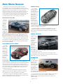
March/April 2008
Volume 15, No. 2
GM Service Information
Goes Global
This first list of categories is the main
Table of Contents.
A team from all of GM’s worldwide
operations worked together to develop
a new Table of Contents, the G-TOC —
or Global Table of Contents. GM’s North
American format was used for most
areas. Engine, Transmission, HVAC,
Steering, Suspension, Brakes and
General Information have not changed.
Other areas have only minor changes.
The big change is in the Body area.
Diagnostic Categories
The new diagnostic approach
offers more information, fewer
words, better formats, and fewer
pages to print. The diagnostics are
now written so you can use your
knowledge and experience to
decide the quickest method to
repair a vehicle.
The new or updated diagnostic
categories are:
• Bulletins by Category
Diagnostic Instructions – Links
to the Diagnostic System Check –
Vehicle (procedures to help prevent
misdiagnosis where there are
When GM sold the most recent
edition of the Pontiac GTO, which was
designed in Australia, it was necessary
to recreate the service manual content
for North America.
• View All Bulletins
continued on page 3
GM Holden in Australia provided a
service manual for the GTO, but its
layout was very different from what’s
in GM Service Information (SI) in North
America. It had to be converted to a
familiar format that technicians knew
how to use in order to make it easy
to find information. Multiply this
situation by all of the vehicles GM sells
worldwide and things could get pretty
confusing.
• General Information
The new SI G-TOC for 2007 and
beyond includes:
As part of GM’s continuing evolution
as a global company, changes have
been made to SI recently so that it can
be used by all of GM the world over.
No longer are there different service
manual styles and layouts for the various GM regions in North America,
Asia-Pacific, Europe or Latin America.
• Campaigns
• Preliminary Information
• Preface
• Body Hardware and Trim
• Body Repair
IN THIS ISSUE
GM Service Information
Goes Global . . . . . . . . . . . . . . . . . . . . . . . . . .1
Strategy Based Diagnosis
Provides an Action Plan . . . . . . . . . . . . . . . .2
Save with UCoat It Epoxy
Floor System Discount . . . . . . . . . . . . . . . . .4
• Body Systems
• Brakes
• Diagnostic Navigation
• Driveline/Axle
• Driver Information and
Entertainment
• Engine
Circuit/System Testing . . . . . . . . . . . . . . . . .4
ASE Certification Tests . . . . . . . . . . . . . . . . .4
Test Your Diagnostic Skills
on the ACDelco LMS . . . . . . . . . . . . . . . . . . .5
Auto Show Season . . . . . . . . . . . . . . . . . . . .6
Tech Tips . . . . . . . . . . . . . . . . . . . . . . . . . . . . .7
• HVAC
Spark Plug Wires . . . . . . . . . . . . . . . . . . . . . .8
• Power and Signal Distribution
Training Update . . . . . . . . . . . . . . . . . . . . . . .8
• Roof
• Safety and Security
G-TOC
• Seats
When using SI, after selecting the
year, make, and model, followed by
“Select a Vehicle Publication to View,”
the “Select a Category” list appears.
• Steering
ON THE WEB
– acdelcotechconnect.com; go to Training
– Log on to ACDelco LMS; go to Resources
– TechConnect Magazine Online
• Suspension
• Transmission/Transaxle
1
Strategy Based Diagnosis
Provides an Action Plan
The idea behind Strategy Based Diagnosis is to provide a common plan of
action for each specific diagnostic situation. Following a similar plan for each
repair provides an efficient way to diagnose and repair all types of conditions.
The Strategy Based Diagnosis chart lists eight diagnostic steps.
ACDelco TechConnect is published
bi-monthly for retail technicians to
provide timely service information,
increase knowledge and improve the
performance of the TSS service center.
Publisher:
Dennis Kissack
ACDelco
E-mail [email protected]
Editor:
Mike DeSander
ACDelco
E-mail [email protected]
Technical Editors:
Mark Spencer
E-mail [email protected]
Jim Horner
E-mail [email protected]
Production Manager:
Marie Meredith
Desktop Publishing:
Supreme Graphics, Inc.
E-mail [email protected]
Write to: 1. Understand and verify the customer's concern by obtaining as much
information as possible from the customer.
2. Compare with another like vehicle that is operating normally under the
same conditions described by the customer to determine if the vehicle
is operating normally.
3. Conduct a thorough visual inspection and gather Diagnostic Trouble Code
(DTC) information.
4. Perform the Diagnostic System Check published in the Service Information.
This will help verify the proper operation of the system in question.
5. Check for related bulletins and Service Information.
6. The four diagnostic categories offer repair guidelines based on if DTCs
are set, if Service Information is available, and intermittent conditions.
Intermittent conditions may require the help of other experienced technicians, evaluating vehicle conditions, testing for faulty electrical connections
and wiring, and capturing data using a scan tool.
7. After isolating the root cause, make the repairs and validate correct operation
by verifying that the DTC or symptom has been corrected. This may involve
road testing the vehicle.
8. If the condition can not be isolated, re-verify the concern. It could be an
intermittent or normal condition.
Refer to the Diagnostic Navigation section of GM Service Information for more
tips on vehicle diagnosis.
- Thanks to Mike DeSander
2
ACDelco TechConnect
P.O. Box 500
Troy, MI 48007-0500
On the Web:
To read and search recent issues of
TechConnect online:
– Go to acdelcotechconnect.com;
click on Training
– Log on to ACDelco LMS; click on
Resources
– Click on TechConnect Magazine
Online
ACDelco service tips are intended for use by
professional technicians, not a “do-it-yourselfer.”
They are written to inform those technicians of
conditions that may occur on some vehicles, or
to provide information that could assist in the
proper service of a vehicle. Properly trained technicians have the equipment, tools, safety instructions and know-how to do a job properly and
safely. If a condition is described, it cannot be
assumed that the information applies to all vehicles or that all vehicles will have that condition.
All materials and programs described in this
magazine are subject to change. Submission of
materials implies the right to edit and publish.
Inclusion in the publication is not necessarily an
endorsement of the individual or the company.
TechConnect is published for ACDelco by Sandy
Corporation, Troy, MI.
©2008 ACDelco. All rights reserved.
GM Service Information Goes Global –
integrated system dependencies),
Strategy Based Diagnosis, and
Diagnostic Procedure Instructions.
the repair. A unique verification procedure will be provided to support the
diagnostic repair.
Diagnostic Fault Information –
The Diagnostic Fault Information table
identifies each circuit that makes up
an electrical subsystem and the associated circuit failure modes. DTCs and
symptoms are listed in the table for all
circuit failure modes.
Schematics
Typical Scan Tool Data – A table
showing a scan tool data parameter
value in reference to circuit failure
modes.
Circuit function symbols are not new,
but usage is more frequent. There are
five core circuit types within diagnostics. The circuit function symbols align
with those circuit types:
Reference Information – Links
providing additional information for
the diagnostic procedure, such as
Schematic Reference, Connector End
View Reference, Description and
Operation, and Scan Tool Reference.
Circuit/System Verification – A nonintrusive description outlining how to
verify that a system or a portion of a
system is functioning correctly. During
the verification process, the vehicle is
kept intact and tested as a complete
system. This verification is used to help
in locating a current or an intermittent
condition.
Component Testing – This category
will offer, when applicable, a static
and/or dynamic component test.
These tests can be used to verify if a
component is not operating properly
to avoid unnecessary replacement. If
the component cannot be tested in a
static or dynamic way, an output control
using a scan tool can be specified.
The new global service schematics
format, significantly based on today’s
familiar schematics, is built to work in
conjunction with the new diagnostic
format.
Diagnostic
Circuit Type
Voltage
Serial Data
Short to
Ground
Open
-40°C (-40°F)
Low Reference
–
Ignition
IGN
AC
xV AC
Reference
Voltage
xV
GM LAN
Ground circuits show a wire coming
out of the component as a solid wire
transitioning to a dashed wire, connecting to a ground symbol. The dashed
wire represents additional harness item
detail. To see all of the circuit detail,
click on the ground symbol to go to
the Ground Distribution schematic.
Repair Definitions
The Engine and Transmission/
Transaxle categories have been updated
with new repair sections for the
mechanical R&R procedures. The Engine
category updates go back to the 2003
model year. Previous model years that
have not been updated have a separate
Unit Repair manual.
These categories have two repair
sections:
• Repair Instructions – On Vehicle
Repair Instructions – On Vehicle
covers replacement procedures. A
replacement procedure is the in-car
repair procedure, including the steps
required to remove all of the vehicle
platform components before accessing
the specific component.
Signal
Signal
Control
Control
Low
Reference
Ground
Ground
Short to
Voltage
140°C (284°F) -40°C (-40°F)
-40°C (-40°F)
B+
serial data circuits are depicted as a
dashed wire from each of the components that are “talking” to each other.
The dashed wires join at a serial data
symbol. To see all of the circuit detail,
click on the serial data symbol to go to
the Data Communication Schematics.
• Repair Instructions – Off Vehicle
Operating Conditions: Engine Running
Parameter Normal Range: -32 to +130°C (-26 to +275°F)
ECT Signal
Battery
UART
Scan Tool Data Example from an ECT procedure
ECT Sensor
Temperature –
PCM Circuit
Schematic
Symbol
Class 2
Repair Instructions – A link to
Diagnostic Repair Verification that
describes how to verify the vehicle
is repaired. All links to Repair or
Replacement (R&R) procedures are
located here.
Repair Verification – This category
will be used only when the Diagnostic
Repair Verification procedure (in Repair
Instructions) does not adequately verify
Circuit Type
Definition
continued from page 1
-40°C (-40°F)
Internal ECM damage may occur if shorted to B+
Subsystem Circuit
Details
Power supply circuits
show all aspects of the
circuit that may affect the
subsystem’s functionality.
To see all of the circuit
detail, click on the fuse
symbol to go to the Power
Distribution schematic.
Serial data circuits are
shown functionally. The
3
Repair Instructions – Off Vehicle
presents separate procedures for
removal, disassembly, cleaning and
inspection, assembly, and installation
for a specific component. For the most
part, these procedures can be followed
top to bottom to perform a complete
overhaul.
Technicians should use their judgment
when deciding which procedure to follow. It may not be necessary to perform
every procedure, based on the repair
that needs to take place. If a crankshaft
is being replaced, for example, you may
not need to remove the cylinder head.
The changes made to the Service
Information offer a number of efficiencies for technicians, enabling quick and
effective diagnosis and repairs. Going
global means better service information
for all GM vehicles, no matter where
they were designed.
– Thanks to Dave Nowak and Lou Winters
UCoat It floor coating systems are permanently bonded to
the substrate and maintain flexural strength in extreme heat
and severe cold. They are designed to move with the substrate without cracking. Road salt and other abrasive materials
as well as oil,
gas, brake fluid
and other automotive chemicals do not
affect UCoat It
finishes. All
that is required
keep the UCoat
It floor looking
good is routine cleaning and general maintenance. Floors
should be cleaned regularly and spills should not be left for
extended periods of time.
Save with UCoat It ®
Epoxy Floor System
Discount
UCoat It is a durable commercial-grade epoxy floor coating that
can give automotive service centers a clean, professional look. The
rugged good looks of the UCoat It floor system deliver on
value too, when you consider that ACDelco offers TSS service
centers a 10% discount on UCoat It products.
The UCoat It product line features floor coating systems,
floor preparation and cleaning items. UCoat It floor systems
have been installed at automotive dealerships, independent
service centers, and in the shops of many professional race
teams, including ACDelco Pro Stock driver Kurt Johnson’s race
shop in Sugar
Hill, Ga.
Sales are based on the initial purchase of the UCoat It Kit
(designed for a 21/2 -car garage) with material-only extender
packs for larger areas. Optional high-gloss topcoat systems
are also available in kits and material-only extender packs.
Multiple colors and finish styles are available to fit virtually any
décor. UCoat It also offers UPatch epoxy crack and floor patch
and USolv, an industrial strength, nontoxic stain remover and
degreaser.
The floor
coating systems come
with a limited
lifetime warranty and feature
commercial
grade epoxy
and urethane products with chemical resistance and abrasion
resistance properties. In automotive service areas, and other
high-traffic, high-abuse areas, the service life is typically 10
years before a recoat is required.
All UCoat It product kits come complete with applicator
tools, mixing pail, clean-up items, product instructions and a
video DVD demonstrating preparation and application.
For more information, call 1-248-545-4055 or visit
www.UCoatIt.com.
– Thanks to Staci Shelton
Circuit/System Testing
Here are some tips to help you understand how to read diagnostic steps
when you are performing circuit or system tests found in GM Service
Information.
Circuit/System Testing is arranged to allow you to perform each test step,
in sequence, until a fault is detected. If the result of a test step is achieved,
the normal flow is to proceed to the next step. If the result is not achieved,
the repair arrow bullet () will identify what actions need to take place.
Intrusive diagnostics are performed to locate the system fault. For
instance, system harness connections are disconnected from the module or
component to test individual circuit functions. The module or component will
be used to assist in verifying the circuit function. When a test does not pass,
the repair steps () will indicate what circuit faults to test. For example, short
to voltage, short to ground or open/high resistance.
When testing for individual circuit faults, you are expected to include
terminal inspections such as connection surfaces and terminal tension at
both the harness and component or module. Additionally, you can use the
links in Electrical Information Reference: Testing for Intermittent Conditions
and Poor Connections or Circuit Testing.
The control modules and components will also be diagnosed during these
test steps. Always retest a control module or component before replacement. For example, re-connect all components and modules and retest the
system to verify the condition still exists before replacing modules or
components.
– Thanks to Dave Nowak
4
Test Your Diagnostic
Skills on the
ACDelco LMS
Just like the real thing, the new ACDelco Diagnostic
Challenge simulations available on the ACDelco LMS put
technicians’ ability to diagnose and repair a vehicle to the
ultimate test.
The new simulations are designed to replicate the
diagnostic process used by technicians in the service center,
and all the necessary Service Information, tools and parts are
provided. The four simulations currently available cover the
HVAC system, brake system, electrical system and engine
performance.
As with real-life diagnosis, the simulated workstation is
dependent on the technician’s ability to diagnose the concern
and complete the repair. The simulation allows the user to
freely navigate anywhere on the screen during diagnosis.
As you progress through the simulation, you need to think
of what the next step is, just as you would do when working
on a vehicle in the shop.
A message points out more information is needed.
High Score
The Diagnostic Challenge simulations are not training
components and do not provide coaching points, but they do
reinforce good diagnostic techniques and repair skills. These
simulations bring the gaming aspect to life as technicians can
retake the simulation as many times as they would like in
order to improve their score.
The Virtual Shop
Upon starting each simulation, a short narrated animation
describes and identifies how to navigate within the simulation and use the various functions.
A technician’s overall score is based upon the amount
of time it takes to complete the simulation while following
the optimum path. The optimum path is the shortest path
to efficiently and quickly diagnose and complete the repair,
as dictated by properly following the Strategy Based
Diagnosis process.
Virtual tools are available to help in the diagnostic and
repair process just as in a shop environment. The simulation
uses tabs on the screen that provide access to Service
Information, the work order, tools (including a scan tool,
digital multimeter, refrigerant pressure gauge set and others)
and the parts counter where you can order parts that you
think should be replaced.
Each simulation begins with one hundred points. One
point is deducted for each choice or selection that is not
part of the optimum path. In addition, after a predetermined
amount of time, one point is deducted for each minute that
passes. At the end of the simulation, a series of questions
are presented and one point is deducted for each incorrect
selection. Points are not deducted for using the Help tab and
obtaining information on how to navigate within the simulation or Strategy Based Diagnosis process. Upon completing
the simulation the overall score will appear.
The technicians that receive the top five scores for each
simulation will have their score, shop name and location
posted to the Simulation Scoreboard on the LMS. To view
the top score, click on the View the Simulation Scoreboard
link located on the LMS training Home page.
Simulations
The diagnostic simulations are accessible via the
catalog search function on the LMS. For example, using
the “Course Name” and “Contains” parameters, and
searching for “challenge” or selecting the course delivery
type “Simulation” will locate the four simulations. The
simulations are:
Using a digital multimeter in the simulation.
Just as the appropriate tools and paths are provided within
the simulation, other paths and tools are provided that are
not part of the optimum path for the given scenario. Because
the simulations are not training components, minimal or no
feedback is given when an incorrect selection is made.
However, if a technician strays too far from the Strategy
Based Diagnosis path or attempts to install a replacement
part without properly diagnosing the concern, a message
offering suggestions may appear during the simulation.
S-AC07-01.01SIM HVAC System Diagnostic Challenge
S-BK05-01.01SIM Brake System Diagnostic Challenge
S-EL06-01.01SIM Electrical System Diagnostic Challenge
S-EP08-01.01SIM Engine Performance Diagnostic Challenge
Are you ready for the challenge?
– Thanks to John Beggs
5
Auto Show Season
Cadillac Provoq
Auto shows are like automotive holidays. And with
most holidays, they come and go before you know it. At
Los Angeles, Detroit, Chicago and New York, along with many
additional smaller shows around the country (and Tokyo,
Geneva and others around the world), GM has introduced a
number of exciting new models recently. Some of these
vehicles will be in showrooms soon, which means they’ll be
in your service centers for maintenance, and others are
concepts that won’t be on the road for a few years.
The Cadillac
Provoq concept
is a hydrogen
fuel-cell crossover
that is based on
GM’s E-Flex
architecture that
debuted with
the Chevy Volt.
The Provoq
combines the
fuel-cell system
with a lithium-ion
battery that can
drive 300 miles on
a single fill of hydrogen — with 280 miles from hydrogen and
20 miles on battery electric power.
Chevrolet Corvette ZR1
This one
is no auto
show concept. The
Corvette
ZR1 is
slated for
a limited
production
run of about
3,000 units.
It features a
supercharged 6.2-liter V-8 producing approximately 620-horsepower and 595 pounds-feet of torque, making it the most
powerful and fastest car ever produced by GM. To top it off,
highway fuel economy is expected to be just above 25 mpg.
The Provoq features a solar panel integrated in the roof to
help power onboard accessories. Fender-mounted charge
ports allow overnight, plug-in charging to extend the vehicle’s
driving range.
Cadillac CTS Coupe
The CTS
Coupe concept
is an expressive sports
coupe that
features
sculpted bodywork and
signature
design cues
from the
award-winning
CTS sedan.
The coupe has the same wheelbase as the sedan, but is
lower and shorter overall.
The front fenders and hood are made of carbon fiber. The
hood features a raised, polycarbonate window with a view of
the intercooler. Start saving now, however, the ZR1 will be
priced around $100,000.
Saturn VUE Green Line 2 Mode
The VUE 2
Mode is the
first frontwheel-drive
vehicle with
GM’s twomode hybrid
technology.
It will deliver
an estimated
50% fuel
economy
increase over
the non-hybrid
V-6 VUE and have a driving range of more than 500 miles,
with no trade-offs in performance from the 3.6L VVT V-6 with
direct injection. The two-mode system uses twin, activecooled electric motors integrated into the automatic transmission that maximize city and highway fuel economy through
two electric continuously variable modes and four fixed
mechanical gear ratios.
Two possible engine choices that the CTS Coupe could
accommodate are the 3.6L direct injection V-6 and a new 2.9L
turbo-diesel currently in development.
HUMMER HX
The HX
concept may be
the next competitor of the
Jeep Wrangler. It
has a removable
roof, fenders
and doors along
with full-time
4WD, front and
rear locking differentials, and 35-inch tires. The HX is powered
by a FlexFuel 3.6L direct-injected V-6.
It is also classified as a Partial Zero Emissions Vehicle
(PZEV) in states that have adopted California’s emissions
rules. Production is expected to begin in late 2008.
For more photos of the latest models making the rounds on
the auto show circuit, go to our website, TechConnect
Magazine Online, by clicking on the Resources link on the
ACDelco LMS.
– Thanks to ???
Saturn also introduced a VUE plug-in hybrid concept that
features a plug-in battery that recharges from 110-volt household electrical outlet in four to five hours.
6
The following technical tips provide repair information about specific conditions on a variety of vehicles. If you have a tough or unusual
service repair, the TSS Technical Assistance Hot Line can help. Call 1-800-825-5886, prompt #2, to speak with a technical
expert with the latest OEM information.
Inoperative Horn
2000-2005 Saturn L-Series
The horn may be inoperative, weak or
muffled, and may have been replaced
previously with an updated unit.
These conditions may be due to
water intrusion. A smaller, updated horn
unit is available with a water deflector
covering the opening. Install the updated horn in an alternate location, identified in the following procedure.
1. If the horn has not been updated to
the latest part, it will need to be
changed to ensure clearance in the
new location.
2. Remove the horn and bracket from
the inner fender.
3. Remove the grill.
point. When this takes place, the
moisture in the air within the lamp
assembly condenses, creating a fine
mist or white fog on the inside surface
of the lamp lens.
Most exterior lamps on GM vehicles
use a vented design and feature a
replaceable bulb assembly. They are
designed to remove any accumulated
moisture vapor by expelling it through a
vent system. The vent system operates
at all times; however, it is most effective when the lamps are on or when
the vehicle is in motion. Depending on
the size, shape and location of the lamp
on the vehicle, and the atmospheric
conditions occurring, the amount of
time required to clear the lamp may
vary from 2 to 6 hours.
Completely sealed headlamp
assemblies (sealed beams) require the
replacement of the complete lamp
assembly if a bulb filament burns out.
Condensation
New horn location
4. Using the existing bracket, mount he
horn to the underside of the top radiator core support on the driver’s side.
5. Lengthen the wiring as needed to
reach the new location Use splice
sleeves from a terminal repair kit.
• May be located primarily in the lens
corners (near the vents) and should
not cover more than half the lens
surface.
• Should clear of moisture when the
vehicle is parked in a dry environment, or when the vehicle is driven
with the lights on.
• A comparison of the equivalent lamp
on the opposing side of the vehicle
indicates a similar performance.
6. Be sure the horn does not contact
the condenser or grill, and properly
secure all wiring.
Water Leak
Exterior Lamp Condensation
• Covers more than half the surface of
the lamp lens.
1993-2008 GM passenger cars and
trucks, including Saturn; 2003-2008
HUMMER H2 and 2006-2008
HUMMER H3; 2005-2008 Saab 9-7X
Some exterior lamps, such as turn
signal lamps, headlamps, or tail lamps,
may have very small droplets of water,
a fine mist or white fog (condensation)
on the inside of the lamp lens. This
may be more noticeable on lamps with
multi-lens designs and may be normal
during certain weather conditions.
Before service, it must be determined
if the lamp shows signs of normal
condensation or a water leak.
Condensation occurs when the air
inside the lamp assembly, through
atmospheric changes, reaches the dew
• Accumulation of water in the bottom
of the lamp assembly.
• Will not clear when the vehicle is
parked in a dry environment, or
when the vehicle is driven with the
lights on.
• A comparison of the equivalent lamp
on the opposing side of the vehicle
indicates a different performance.
Reverse Lamp Inoperative
2003-2008 Saab 9-3
The left-side reverse lamp may not
illuminate. There is no power to the
circuit. There may be no change if the
Rear Electrical Center (REC) is
swapped.
7
The circuit for the left-side reverse
lamp is also tied into the rearview
mirror auto-dim circuit. In the REC,
connectors H2 pin 11 and T-C pin 1 are
the same circuit, as they are jumped
together internally. (See the reverse
lamp schematic.) This circuit supplies a
signal to the rearview mirror to disable
the auto-dim feature when backing up.
If the REC sees any circuit shorted to
ground, it will disable the circuit by
removing the voltage for protection. The
REC will continue to disable the circuit
until the concern has been rectified.
Verify the integrity of the circuit in
question for shorting to ground. The
rearview mirror may be improperly
installed, trapping the wiring between
the mirror and the body, pinching the
wires and shorting the circuit to ground.
Front Suspension Noise
2003-2008 Saab 9-3, 2004-2008
Saab 9-3 Convertible, 2006-2008
Saab 9-3 SportCombi
A popping or clicking noise may be
heard coming from the front suspension area. It may be described as a light
metallic sound, typically heard while
turning at slow speeds.
Follow normal diagnostic procedures.
If the noise is resonating from the
hub/lower strut area, remove the front
backing plates/dust shields and enlarge
the mounting holes to prevent any
bind/slip-stick condition from occurring.
Reassemble and then test drive to
verify the repair.
Product Assistance
For assistance and information
regarding specific ACDelco
products, contact these free
information hotlines:
Brakes – 1-888-701-6169 (prompt #1)
Chassis – 1-888-701-6169 (prompt #2)
Clutches – 1-888-725-8625
Lift Supports – 1-800-790-5438
Shocks – 1-877-466-7752
Starters and Alternators –
1-800-228-9672
Steering – 1-866-833-5567
Wiper Blades – 1-800-810-7096
Spark Plug Wires
The first high-tension spark plug
wires were simple strips of copper
running from the distributor to the
spark plugs. As the lengths of copper
increased, it became necessary to
insulate the copper wires to reduce
Radio Frequency Interference (RFI).
Radio Frequency Energy
The ignition system of an internal
combustion engine radiates various
amounts of Radio Frequency (RF)
energy, which acts like a radio transmitter. If this energy is not suppressed,
the radiated RF energy can cause
interference and disruption of the radio,
headlight dimmer, garage door opener
or other sensitive electronic devices.
The best defense against RFI in
the ignition system combines TVRS
(Television Radio Suppression) cable
or wire wound cable in the spark plug
wires with ACDelco’s resistor-type
spark plugs.
TVRS Cable
RFI that is transmitted from the plug
wires comes from the instantaneous
discharge of the high voltage as it arcs
across the spark plugs. The wires then
act as antennas to transmit the resulting
RF energy into the surrounding underhood area.
To suppress RFI and increase
performance, early plug wires traded
copper for carbon as a conductor. The
carbon-impregnated fiber or wire core
helps suppress RFI because the high
resistance makes the wires ineffective
antennas. High resistance in the spark
plug wires
will slow
down the
energy
build-up to
ionize the
spark plug
gaps.
A visual inspection of the spark plug
wires should include checking for:
Wire
Wound
Cable
A resistance test also can be
performed to check the conductivity of
the wire. Perform the test while flexing
the wire. Look for high resistance or an
open circuit. The resistance test is a
static test. The resistance will change
dynamically when the spark plug is
operating. An oscilloscope may be able
to pick up the change by monitoring the
voltage.
• Breakdowns in the insulation, including the heat shields on the boots
• Oxidation on the terminal
connections
• Poor terminal connection
TVRS cable
An alternative to TVRS cable is wire
wound cable, which can be more effective at reducing RFI. The wire wound
induction cable makes it possible to
reduce series resistance while still maintaining RFI suppression. The reduction
in series resistance allows more of the
coil energy to be supplied to the spark
gap. Essentially, the lower cable resistance provides a hotter spark, longer
spark duration and cooler operation.
Suppression in a wire wound core is
due to the magnetic field that is created
around the core when the spark is
jumping the gap. The energy in the
magnetic field prevents any other
electromagnetic energy from radiating
until the magnetic field has collapsed.
In general, carbon or silicone spark
plug wires will measure 5,000 ohms per
foot or less when doing a static resistance check. Wire wound cables will
measure lower resistance, fewer than
1,000 ohms per foot.
Spark plug wires should be replaced
any time they show physical damage,
such as cuts, chafing, scorch marks or
signs of external arcing.
Plug Wire Testing
Ultimately, a single open spark plug
wire can lead to a failed ignition coil or
ignition control module.
Because of its construction, spark plug
wire cable can be damaged by grabbing
and pulling it away from the spark plugs.
Rough handling can separate the conductive strands from the center terminal.
An open circuit, poor conductivity,
excessive resistance or a spark plug
misfire is the usual result.
For more information on spark plug
wires and ignition systems, two available
Web-Based Training courses on the
ACDelco LMS are: S-EP08-01.01WBT –
Powertrain Performance 1 and
S-EP08-02.01WBT– Powertrain
Performance 2.
– Thanks to Mike Militello
Automotive Air Conditioning: Advanced Refrigerant System
Diagnostics
How to Take ACDelco Training
S-AC07-02.01ILT
Go to acdelcotechconnect.com and click on the
Training tab to log on to the ACDelco Learning
Management System (LMS).
• To enroll in an Instructor-Led Training (ILT) course,
click on the Enrollment link or the Instructor-Led
Courses link.
• To launch a Web-Based Training (WBT) course,
click on the Web-Based Courses link to view the
catalog and select a specific course.
• To launch a TechAssist (TAS) course, click on the
TechAssists link to view the catalog and select a
specific course.
S-AC07-03.01ILT HVAC Control System Operation and Diagnostics
Current Instructor-Led Training
S-EP08-04.01ILT
S-BK05-01.01ILT
Braking Systems
S-EL06-04.01ILT
Body Control Systems Diagnostics
S-EL06-10.01ILT
Battery, Charging, & Starting
S-EL06-11.01ILT
Automotive Electrical Circuit Diagnosis and Repair
S-EP08-01.01ILT
Engine Performance
S-EP08-02.01ILT
Engine Performance: Computer Controls and Ignition System
Diagnostics
S-EP08-03.01ILT Engine Performance: Air Induction and Fuel System Diagnostics
Engine Performance: Fault Monitoring and Emission System
Diagnostics
S-EP08-12.01ILT OBD II GM Diagnostics
ACDelco’s Instructor-Led Training (ILT) courses provide hands-on instruction with the latest automotive
S-EP08-81.01ILT Duramax 6600: Diesel Engine Performance
systems. The following ILT courses are currently being
S-SS04-01.01ILT Vibration Correction Diagnostics
held at training center locations around the country.
S-ST10-01.01ILT
TS-PU-0006-08
8
Supplemental Restraint Systems