1
HP Archive
This vintage Hewlett Packard document was preserved
and distributed by
www. hparchive.com
Please visit us on the web !
On-line curator: Glenn Robb
This document is for FREE distribution only!
~ 1IIIn IRIlfl
SERVICE INFORMATION FROM HEWLETT-PACKARD
JANUARY-FEBRUARY 1974
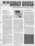
CLUES TO HELP
DETERMINE THE UP
PART NUMBER OF A
REPLACEMENT PART
b)' Rod Dinkins
Have you ever searched through the
parts list in an Operating and Service
Manual trying to determine the HP
part number of a needed replacement?
If so, there have probably been times
when it was difficult to determine the
desired number. It is not uncommon to
find several part descriptions that
seem to apply to the part that you need.
How do you determine which is the correct number? One way is to call your 10-
eal HP office. An even faster method,
though, is 10 use the clues given by the
part number of each part.
If you frequently use HP parts lists,
you have probably noticed that similar
parts have similar part numbers. That
is, there appears to be some pattern in
the numbering system. Although there
are variations and exceptions, the organization of the part numbering system can be broken down into three major classifications: (1) Components
and materials, (2) General usage
parts, and (3) Specific instrument
parts. A knowledge of the basic structure of the part numbering system simplifies identification of part types or
part numbers. In this article, we'll examine each classification and show
some typical examples.
Component Parts and Materials
These are items that you might expect
to find stocked at a local electronics
distributor; items that might be used
by any electronics manufacturer. For
example, transistors, ICs, transformers, capacitors, resistors, nuts,
screws, grommets, tubes, switches,
connectors, batteries, etc. For com-
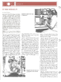
The tips In this article will help you to determine needed part number•. If you need
assl.lance, Identification expert••uch a. Paul Gobin ar. available to h.lp. Pi.... contact
your local HP office.
ponent parts and materials, eight digit
part numbers are used, where the fourdigit prefix identifies the type of component, part, or material and the fourdigit suffix indicates the unique part.
Table 1 is a list of some of the more
commonly used prefixes for component parts.
Knowing this system has two benefits;
first having information about the part
will give you clues about its part
number. For example, if the part you
are replacing is an electrolytic capacitor, you know that the HP part number
must begin with 0180-. Second,
knowing the part number gives you
helpful information about the part. For
example, if you are working on a circuit with a transistor with part number
1854-0037, you know that this transistor is an NPN made out of silicon.
Therefore you can expect to see about
0.6V across a forward-biased baseemitter junction. A transistor with an
1850- or 1851- prefix is germanium
and therefore you should expect
about O.2V drop across its B-E junction.
IN THIS ISSUE
NEW SERVICE NOTES
HIGH FREOUENCY
POWER LIMITER
PARTS IDENTIFICATION CLUES
NEW VIDEO TAPES
SERVICE TIPS
Pulse generator waveform
Magnetic tape discontinued
RACING QUIZ
PARTS IDENTIFICATION
Specific Instrument Parts
Table 1
PREFIX
COMPONENT/PART/
MATERIAL
PREFIX
0121-
Capacitors. Variable
1251-
(mechanical)
0122·
capacitors, Voltage Variable
014001500160-
CapaCitors. FiXed!
NonCapaCitors, Fixed
Capacitors, Fixed ElectrolytiC
0160
033003400370038004100470049005100674lhru 0778-
Capacitors, Fixed Electrolytic
Insulating Materials
Insulators, Formed
Knobs. Control
Spacers and Standoffs
Crystals
Adhesives
Relays
Fasteners
Resistors, Fixed (non-wire
(semiconductor)
wound)
0811thru0831- Resistors (wire wound)
1200Sockets for components
1205Heat Sinks
1250-
ConnectOts (RF and related
parts)
General Usage Parts
There are quite a few parts that are
built by HP 10 be used in many different HP instruments. The main characteristic of this category is that you
would not expect 10 find any of these
parts used in a competitor's product,
unlike the previous category discussed. These include such items as
covers, side frames, rack mounting
hardware, etc. An example of this is
side frame 5060-0732; this is an assembly used in the 5245L, 5244L,
5242L, 5065A, and others. Table 2
gives the prefixes for general usage
HP manufactured parts.
Table 2
COMPONENT/PARTI
MATERIAL
COllnectors(nonRFand
related parts)
Bearings and Bushings
Batteries
Monolithic Digital Integrated
Circuits
1826Monolithic Linear Integrated
CirCUits
1850Transistors, Germanium PNP
1851Transistors, Germanium NPN
1853Transistors, Silicon PNP
1854Transistors, Silicon NPN
1855Field-Effect-TransistOfs
1884Thyristors and SCR's
1900-thru 1912 Diodes
192o-thru 1952- Vacuum Tubes
1990Semiconductor Photosensitive
and Light-Emitting Diodes
2110Fuses
2140Lamps
3100- thru 3106- SWitches
8120Gables
9100Filters and Trans/ormers
141014201920-
to be used in many instruments and
that it is a plastic molded part. From
this and the previous listing, it's very
likely that the PC guide will have the
prefix of 5040- to 5059-. This will help
to locate the correct part in the table of
replaceable parts. The part number
for a commonly used PC guide is 50400170. An example of a component
used in several instruments is power
splitter 5088-7003. Thus if the part to
be replaced appears to be one made
by HP and used in many HP products,
the part number probably has eight digits and the first digit is a 5. The third
digit will indicate additional information
about the item.
These are parts manufactured by HP
for use in a particular HP instrument or
series of instruments. These parts
have ten digit part numbers; the prefix
is the model number of the instrument
and the suffix indicates the type of
part. Table 3 is a list of suffixes commonly used.
As an example, assume that you are
looking for the part number for the
main chassis for Model 5340A. Since
this is likely 10 be used only in the
5340A and because it's a sheet
metal part, you will conclude the number will most likely be 05340-0NNNN.
After scanning the parts list under
chassis parts, you would find the part
number is 05340-00003.
Some clarification of the above categories may be appropriate. "Sheet
Metal" includes items that are
stamped out of sheet metal, folded if
necessary and perhaps painted.
Many front panel parts fall into this
category. Also included are items
made out of sheets of other material,
such as an insulator made from a
sheet of bakelite.
A part is assigned a -2NNNN suffix
when the last operation performed is a
machining operation, such as drilling a
Table 3
TYPE OF PART
PREFIX
Sheet Metal
Machined
Molded
Assemblies
Components
SOOOS020504050605080-
to
to
to
to
to
50195039505950795099-
As an example of use, assume you
have a broken guide used for printed
circuit board support. Upon examining
the part, you determine that irs likely
TYPE OF PART
Sheet Metal
Machined
Molded
Assembly
Cumponent
Documentation and
special parts
PIN SUFFIX
(Ne::=Any Number)
-ONNNN
-2NNNN
-4NNNN
-6NNNN
-6NNNN
-9NNNN
PARTS /DENT/FICA TiON
hole. Other machining operations indude milling, threading and lathing. A
molded part can be recognized by the
unique shape that results from a mold.
A part is considered an assembly if
one or more parts were combined to
make the part. Did someone put together the desired part? A switch purchased from a supplier would have a
number such as this: 3100-NNNN. If
someone soldered wires or components on the switch, it would then be
considered an assembly and assigned an appropriate number. Component numbers are used when a particular component was designed for
use in a specific instrument. An example of this is a special hybrid circuit or
device such as a sampler. A mask for
a front panel indicator may have a
BNNNN suffix. Documentation indudes operating and service manuals
and other printed matter. Special parts
may be supplied in instruments ordered with a specific modification. For
example, if you are repairing a board
with pIn 05326-90002, the 9 indicates
that this board is "special" and therefore is different from the board normally supplied in the instrument.
digit part number beginning with
as.
3)
Is this part manufactured by HP for
use in one or a few HP products? If
so, it will probably have a ten dtgit
part number and the first fIVe digits
are related to the product's model
number.
If the second or third category is
chosen, we next ask if the part is:
a) made out of sheet metal
b) machined
c) molded
d) an assembly
e) a component
What can you determine about the desired part number?
_
An examination of the paper tray for
this instrument leads us to the conclusion that the part is unique enough
that it probably was designed by HP
for only this HP product. Therefore it
has a ten digit part number and the
first five digits will be the product model number: 05055-NNNNN. Further examination reveals a curved shape indicating that the item is molded. Therefore the first digit in the suffix is a
4, so our number is narrowed to
OSOSS-4NNNN.
Let's assume that the service manual
lists five parts with descriptions that
might be what we want (such as paper
holder, paper support, etc.). These
are:
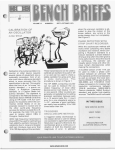
Here's a short quiz to further illustrate
the point. Let's say you are working on
an HP 5055A Digital Recorder and
after repairs you notice the paper tray
is damaged. What is the HP part
number? Instead of randomly searching through the parts list, we first determine a great deal by examining the
part.
1)
Is this a component (that is, is this
a part that might be stocked at a local electronics distributor?) If so,
it has an eight digit number.
2)
Is this part manufactured by HP for
use in hundreds of H? products? If
so, it will probably have an eight
a)
b)
c)
d)
0)
IIIIIDBI
05OS5-()()()()S
05OS5-40001
05OS5-00004
05OS5-2000S
5060-0099
Which part is the one desired? We concluded our part was used only in this instrument. Therefore answer e can be
ruled out. The desired part is also
molded, and answer b is the only one
that fits this description. Therefore
05055-40001 is the part number of
this paper tray.
Some variations on this part number
system may be noticed in some divisions and in some countries. Also previous part numbering methods were
used that did not incorporate the features of the present system. The previOt:s system used numbers such as
560A-37AK. Also some firms acquired
by HP had their own methods of assigning numbers. Many of these
numbers are still in use today. Therefore the techniques presented above
will not help you 100% of the time, but a
great amount. Investing a few minutes
learning the system pays big rewards.
Try it; it works!
Rod Dinkins is a writing supervisa at the Santa Clara (California)
{);vision of HP. His responsibilities
include aN the Operating and Ser·
vice Manuals for instruments manufactured there.
His outside interests are
many, including photography,
bridge. and building model cars. He
;s ma"ied and has two boys.
11ElB11
SERVICE TIP
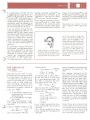
PULSE GENERATOR
WAVEFORM ERROR?
by Gunter Schade
If you work with pulse generators
or repair them you may have noted
a special effect on some instruments
which raises the question to service
people and customers: is this an
error or not?
appears when each channel is set
to full amplitude of about 4V but
when only one channel is used (and
therefore, terminated by 50a)while
the other unused channel is
not terminated. Since the output
stage is a difference amplifier and
both collectors are connected to the
"iO
Z.o
J~
UJ;t"
Guenter Schade has been with
HP fDr six years and is currently a
Customer Service Engineer at the HP
factory in Boeblingen, West Germany.
This job entails solving service related
:--.:, eu
This apparent error appears as a
releNt£!?
Similar symptoms may appear with
other models.
This strange behavior is caused by
an incorrect impedance match and
®
S6TTtNq ON &~A
WH6N EIi!~ APPEfA/2:!:
NEW SERVICE-ORIENTED
VIDEO TAPES AVAILABLE
i2
..
\
-
use a 50n load for each channel or
switch the attenuatar of the unused
(open) channel down to a lower
range.
In conclusion, if you ever use a
pulse generator, watch for correct
termination. This may save a lot of
time looking for the problem.
I
1;0
°i~
bend in the middle of the leading
edge on the aOOBA Pulse Generator.
output connectors, the difference
amplifier is not able to work correctly with different loads (different current) when the generator is
used as described above. To avoid
this bend in the waveform, either
.Ir~~~.
n
Two new service-oriented video tapes are available
which should be especially valuable to service personnel. The programs cover the mechanical and electrical
aspects of the 1700A Oscilloscope Series.
problems for electronic products.
Previously Guenter designed some of
the unique electronic fixtures and tools
used in the manufacturing of HP products at Boeblingen. In addition to
spending a lot of time skiing, he enjoys
tabte tennis.
1) 1700 OSCILLOSCOPE SERIES (SERVICE
3)-1710A MECHANICAL
The significant mechanical aspects of the Model
1710A Oscilloscope are reviewed, with emphasis on
control groupings and how to remove most of the
assemblies and the CRT. Personnel who have to service the vertical attenuators or remove the horizontal
module or CRT of the 1710A will find this program
very useful. HP stock number 90030_#797. (Time:
14 minutes).
2) 1700 OSCILLOSCOPE SERIES (SERVICE
4)-1710A ELECTRICAL
Block diagrams and simplified schematics are used
in this program to clarify the operation of the low voltage power supply, the bright scan mode and the
logic-controlled trigger circuit of the 1710A Oscilloscope. Major electrical aspects are examined, and
the troubleshooting tips offered will be of great practical help to service personnel. HP stock number
90030_#798. (Time: 14 minutes).
These two tapes are part of a four-part series on the
1700A Oscilloscope series. Operation was covered in
tape 90030_#673. Power supplies are reviewed in
tape 90030_#674.
To order these tapes, or for more details, contact your
local HP Office.
QUIZ /
CAN YOU SOLVE THIS?
Since service work requires a very
logical procedure to get optimum results, here's a challenging exercise to
test your logic. It may be ideal to try
this one when you are relaxed and
away from the noise of the shop because this puzzle may require deep
concentration. It can be solved with
the clues given so don't give up easily.
Good Luck!
One day five young aspiring HP technicians were finishing a day of repair
work. One was Japanese, another
was Italian, another was German, another was English and another was
American. (If you think that that is
strange, read on.) They decided to
have a race to the local bar to share a
drink and extend their best wishes for
a prosperous New Year.
Now this was not an ordinary group of
service personnel because their cars
were a Datsun 240Z, Volkswagen
Superbug, Fiat 850, Triumph TR4 and
a '56 Chev with one bald tire. One of
the above cars was marked #1, an·
other marked #2, another #3, another
#4 and another was #5. (It also
seems that they were racing enthusiasts).
From the information in the clues below, answer these questions:
1. Who finished first in the race?
2. What car was he driving?
3. What number was labeled on it?
Similarly determine the same for the
second, third, fourth and last place
people. That is, fill in the table.
MAGNETIC TAPE
DISCONTINUED
by Vern Hudson
Some versions of the 3960A Instrumentation Tape Recorders, such as
the 3960G·E14, are equalized for 3M
Type 203 Audio Tape. Others, such as
the 3960G·E51 are equalized for 3M
Type 150 Audio Tape. 3M has recently
announced the discontinuance of
Types 150 and 203 tapes. Also, they
do not have a direct replacement for
REPLACEMENT PART
Here's what you need to solve the
problem:
a.
No driver had the same
nationality as the country
of manufacture of his
car. (Japanese did not
drive the Datsun, Italian
did not drive the Fiat,
etc.)
b.
The Datsun finished behind the Fiat (not necessarily directly behind).
c.
The driver of the Chev
had to stop to change a
flat tire.
d.
The Italian won the race.
e.
Car #3 did not finish in
the first two places.
h.
No car finished the race
in a place that corresponds to ils number.
(Car #1 did not finish
1st, Car #2 did not finish
2nd, etc.
Make of
Car
The driver in Car #3
worked for HP two years
longer than the driver of
the Fiat.
The American is 6 feet
tall and weighs 270
pounds.
The driver that finished
in 4th place has a
mother-in-law who is bigger than the American.
k.
The Volkswagen was
painted green.
The Chev finished last.
The driver of #2 was
older than the American
but younger than the
driver of the Volks·
wagen.
The American was not
driving Car #4.
The Triumph had a broken windshield wiper.
g.
II~I
o.
The Englishman finished
ahead of these three different cars: the Fiat, the
Chevrolet and the car
labeled #1.
Number labeled
on Car
Natlonallty
of Driver
Winner
2nd Place
3rd Place
4th Place
Last
these two audio tapes which would
meet all specifications of these special
versions. Extensive testing at San Diego Division has verified that a direct replacement for the 203 tape is the Ampex Type 641 tape. The 3960A series
recorders equalized for the 203 tape
will meet all specifications when using
the 641 tape, and in fact, the 641 is being supplied with the 3960's which previously used 203 tapes. For replacement purposes, the 641 is available
under HP PIN 9162-0060. A replacement for the 150 tape is being tested
and the replacement will be an-
nounced as soon as it is available. All
other standard versions of the 3960A
series require 3M 951 tape, HP PIN
9162-0006.
Vern Hudson is a Service Engineer for Recorders and Plotters at the San Diego
California) Division of HP. Service Engineers are product experts that provide
technical assistance to the HP Field Service Organizatidn. Vern also contributed
an article on tape recorders that may be
of interest in the November-December
1973 issue of Bench Briefs.
'--II
SERVICE TIP
IS THIS NORMAL???
by Brent Helland
It is in poor taste these days to speak of
"normal". Anthropoligists, sociologists
and psychologists have about given
up trying to define normal. It is even
harder than it may seem to define "normal" as it applies to machines. On the
Should this screw be this long?
Is this normal?
other hand, one of the virtues of a
deeply experienced serviceman is an
almost instinctive feel for deviations
from normal operation in a circuit. So,
it's to your great advantage to devise a
strategy that helps you to better determine what is normal for any particular
instrument.
How does "normal" apply to electronic
gear? Let's examine some practical
definitions of normality.
"Normal" could be thought of as "within specifications". It is possible, however, to find deviations from normal
within specifications. For instance, an
instrument that functions properly
may show some indication of possible
failure six months hence. Such indications may be minor, yet stem from major causes. A drop of oil on the chassis
of an instrument could be from a defective capacitor that will explode within
weeks, or perhaps hours. The drop of
oil and similar, even more subtle indications can be caught if you will prepare a checklist of things to look for.
Add to the list as you think of new entries, such as a drop of oil, a cracked
p.c. board, a loose ground, etc. The
list will ultimately cover a page or so,
but will still require only a few moments to check out.
"Normal" could be thought of as usual
or mean performance.' Is a tiny
amount of jerk in the transmission of a
recorder acceptable? The paper
moves at the specified speed, but
from experience, you know that the
paper should move smoothly. Inspection will reveal a jerking clutch. Had it
locked, it could have done hundreds of
dollars worth of damage. Smooth performance is usual, but not specified.
Take a moment every so often, while
troubleshooting or testing, to deliberately try to sense how the machine is
running. Touch the paper feed roller,
Should this recorder have such
a wide trace? Is this normal?
does it move smoothly? Look at the
display, is an LED too dim? Listen for a
whine or clunk or rattle.
"Normal" could be thought of as being
efficient enough and not requiring
remedial action.' For example, a radio operator may continue to take messages from his receiver despite noise
or poor fidelity, and say that the receiver operates normally until it requires remedial action because of a total failure (no reception at all).
One user's oscillographic recorder
yielded more power line frequency interference when grounded than when
floating. The user considered this peculiarity to be normal for this instrument so he left it floating and tolerated
the smaller amount of hum. Investigation revealed that this "ground" was
an ungrounded window grating that
was twenty feet from a high voltage
power line. Recordings became free
of perceptible hum when the recorder
chassis was properly grounded.
When an operator claims that his gear
worked normally until its recent malfunction, ask a few questions. Find out
just what he means by "normal". His
answer may save valuable troubleshooting time.
"Normal" could be thought of as an
unspecified condition that is necessary for proper instrument function. If
2V2 milliwatts of R.F. power into
the regulator is necessary to produce
SERVICE TIP
a levelled outpuI, 2V4 won't do. The
2V2 milliwans is not specified but the 1
milliwatt of levelled output is specified.
Common sense might dictate that 2%
times the output should be more than
enough power 10 ensure levelling. Any
serviceman would be helpless to repair this instrument until he knew what
the normal input power should be.
spection, deliberate sensitivity to the
peculiarities of an instrument, and a
readiness to seek help will reduce
down-time and minimize re-repairs.
One of the most important of maintenance procedures is to take notes
(preferably in the instrument service
manual) that describe normal operation forthe instrument at hand. Any des-
II~I
cription of normal operation will help
you work more efficiently, since any
divergence from normal (however subtle) provides a valuable tool for troubleshooting.
1Abercrombie, M.L. Johnson, The Anatomy of Judgment, London, 1960, pp 94108.
If you are stuck in a circuit that dis-
plays unreasonable symptoms, it is
possible that you have made invalid
assumptions about what is normal for
the circuit. Many times it will clear
things up to make careful measurements throughout the circuil, note
them, then call the nearest specialist
to find out which measurements are
abnormal.
To summarize, it appears that "within
specifications" is a good start at defining normal operation for electronic
gear. Our definition, however, needs
expansion to include "usual performance" and "unspecified conditions
for operation" to make it really useful.
ual for the miniature Probe Voltmeter. Brent previously spent 8
years at the HP Englewood, Colodradosales and Service Office working both on the service bench and
as part of the on-site service force.
Brent Helland is currently a technical writer with the Loveland (Colorado) Instrument Division of HP. His latest project was the operating man-
The streams and wooded areas of
Colorado fit well with Brent's interests of fishing and hiking. He is active in church work and also enjoys
reading. Brent is married and has
two children.
An orderly approach to mechanical in-
THE ORIGIN OF
by George Stanley
Many of you who work in radar,
communications or receiver testing
are familiar with the expression
-114 dBm as the residual background noise level that is present
when using a 1 MHz bandwidth.
This noise level is derived from
the expression: KTB where K is
Boltzman's constant (which is
1.38 x 10'23
~)
T is the noise temperature (in
degrees Kelvin) of the device
being measured.
B is the bandwidth of the system (in Hz)
For a 20°C environment K is 273°
+ 20° = 293 0 K. If bandwidth is 1 MHz
then KTB =
1.38x10⁻²³~ x 293°K X106~
= 1.38 x
Therefore KTB =
watt-sec
1.38 x 293 x 10-17
= 4.04 x 10- 15 watts
= 4.04 x 10⁻¹² m watts
The decibel (dB) is often used to
express the ratio of a power level
P x to some reference power. The
term dBm is used when the reference power level is lmw. Thus,
----sec-
-114 dBm
2~~ x 10-17 ~
sec
But 1 joule equals 1 watt-sec
sec
dBm = 10 IOg10 (~)
lmw
(See the April 1973 issue of Bench
Briefs). Let us convert KTB to dBm.
AbSOlute Power Level
" 10109'0 ( 4.04 ~~~'2mw )
" 10109,0 (4.04)( 10'12)
"10[109'0 (4.04) + 10910 (10- 12)1
"10(1°910 (4.04) -1210910 (10)]
"1010.6 -12(1))
"101-11.4)
" -114dBm
For a 10 KHz bandwidth
retical background noise
-134 dBm.
For a 100 Hz bandwidth
retical background noise
-154 dBm.
the theowould be
the theowould be
For a 1 Hz bandwidth the theoretical
background noise would be -174
dBm.
One practical implication of the
above is that if you use a very narrow
bandwidth and digital coding (high
or low signal) you can pass intelligence over long distances such as
deep space with very low power
(battery operated) transmitters. This
is just another reason why so much
of our electronics is going digital.
Not only do we use digital techniques for deep space communications, but then we use "digital
enhancement" techniques to integrate out some of the noise which
is random in nature and enhance
the digital signal which is repetitive
in nature.
George Stanley, who is probably familiar
to many readers as the author of a book
and videotape series on transistor basics,
is a regular contributor to Bench Briefs.
He is the Group Training Manager for
HP's instrument producing divisions.
\IIBBII
HIGH FREQUENCY
OVERLOAD PROTECTION
Model 11693A Limiter protects inputs from up to a 75W
peak or 1 Watt continuous power. Also signal generators can be protected from application of reverse power.
A limiter is available that provides input protection for
a variety of instruments. Many limes the input circuits of
spectrum analyzers, samplers or amplifiers can be
damaged by excessive input signal levels, These could
be either transients or short duration overloads.
A typical application, shown in Figure t, is the protection
of a spectrum analyzer input from inadvertent overload
due to high level signals from an antenna.
The Limiter has Type N connectors and an insertion loss
of less than 2dB. For more information call your local HP
Office.
Figure 1.
Here's the latest listing of Service
Notes available for Hewlett-Packard
products. Service Notes contain
information that will help you get the
most out of your purchases.
Many times design changes or other
improvements are made in products
currently being manufactured. HP
often recommends including these
changes in products previously
sold; this is done by writing a
Service Note for the product.
Service Notes for your instruments can
be obtained by using the Service Note
Order Form. Remove the order form
and mail it to the HP distribution center
nearest you. European customers
should mail it to this address:
Hewlett-Packard S.A.
Central Mailing Department
P.O. Box 7550
Freeport Building
SCHIPHOL-eentrum
The Netherlands
For the U.S. and elsewhere, mail it to:
Hewlett·Packard Company
195 Page Mill Road
Palo Alto, California 94306
GENERAL
MSO AutogriplrlStaliationandclå procedure.
(lIIlplIfSedest.448andautogrip)
M51 A1IX-YRecordefliandgraphicplol1ers.Mylarlest
grids not recommended.
M53 EquipmOl1tne<:essarytoCalibrateandctleckptlfformanceof HP Real nme OsCIlloscopes. (super·
seoeserroneouslynumbefedS.N. M-51)
141A STORAGE OSCILLOSCOPE
141A/S·19 All serial pl"eti~es_ CRT Neck Pin
Location
1411 SPECTRUM ANALYlER-DISPLAY SECTION
141T·3 All senal pl"eti~es. Fa-stand Standard Mode
AdjuSlments uslng spectrum analyzer plllg·ins.
141T-4 All serial pl"efi~es. Cooling Ian modification
236A TELEPHONE TEST OSCILLATOR
236A/AH·l Telept10ne Test Oscillator (Model236A
serials 1107A04460 and below: Model 236AH
serials 1107A04565andbelow;Model KS-I9353-L4
aliserialll).ModilicaliontoimPfoveamplitudellat·
ness above 100 kHz.
4038 AC VOlTMETER
4036-5 Serials 523-05300 and below. Modilicationto
;:ace germaniumtranllistorllwilhsiliCOl11ransiS435A POWER METER
435A·1 Serial Pfefix 1234A and below. Modification
lor long inpul cables.
NEW SERVICE NOTES
489A MICROWAVE AMPLIFIER
489"·6 Allsllfial prefi~es.lnslallationof Improved
~~:s~aIUp<lallr1'\l.SuperSedesalipreviou$
491C MICROWAVE AMPLIFIER
491C-6 All sarialprelixes, Installalionolimproved
TWTarldgeneralupdaling. SUper$&dBS all previous
servicenotas.
6518 TEST OSCILLATOR
651B-U·l000 Serials 1201UOO925 and below. Power
Transistor Replacemeol.
7418 DIFFERENTIAL VOLTMETER
.
_
~
7418-7 All serials. Replacement of resistor in AC
7418-8 All serials. Padding capacitors used for AC
probeleplacem&nl.
11064 TUNNEL DIODe
llQ6A·tA All sOfial prefixes. Repair policy (super·
sedes 1106"-1)
1200A SERIES OSCILLOSCOPE
1200AiB·5 All serial prefixes. Preferred replacement
lorA604
1200AIB-6 All serial prefixes. Nut adapter for Inleosily
eo
1201A!B-5 All serial prefixes. Praferredrep!acement
lorA604
1201A/B·6 Allsariel prellxes. NUl adepterfOf Intensity
eo.
1202AJB-2 All serial prefixas, PrefOlTedr~acament
forA604
1202A1B-3 All serial prefixes. Nut adaplerfor Intensity
eo
1205Al8-2 All serial prefixes, Prelerredrepjacement
forA604
1205A1B-3 All serial prefixes. Nut adapter lor Intensity
eo.
f206A1B-2 All serial prefixes. Preferred repjacement
forA604
1206AJ8-3 All senal pretixes. Nut adapter for Intansity
eo.
1207A1B-5 All serial prelixas. Preferredrepjacement
forA604
1207A1B-6 All serial prefixes, Nut adapter for IntenSIty
eo.
'208AlHl'-4 Serialprelix1306Aandbelow.Highvoltageoscillatordouble·modingandprelerredr.
placement lor A604
'208AlHl'-5 Serialpre!ix 1330A and below. Polen·
tial trace shorting problem
1208AJHI1-6 All serial prefixes. Tips for recognizing
and Identifying storage CAT symptoms.
1215A!B--l All serial prefixes. Prafarredreplacement
lorA6Q4.
1215AJB·2 AH serial prefixes. Nut adapter lor Intensity
eO
1217A1B·2 All serial prefixes. Preferred replacement
lor ASQ4.
1217A1B-3 All serial prllfixes. Nut adaplef lor Intenslty
eo
1300A X_Y DISPLAY MONITOR
1310A COMPlJTER GRAPHIC DISPLAY
1310A·9 Serial prelix 131M only. Prllfefred replace·
mentforA5.
1310A-l0 All serial prefi~es. Stock numbers for or·
dering mask assemblles
1310A·l I Serial prefix 1316A and be4ow. Possibl~ty
of insufficient gain raJ19llafter replacing A1U2or
AJU'
1311A COMPUTER GRAPHIC DISPLAY
1311A-9 Serial prefix 1316Aonly, Preferradreplacementlor A5.
1311A-l0 All serial prefixes, Stock numbefs lor oroering mask assemb~es
1311A_l1 serial prelix 1316Aarld below. Possibi~tyol
insufficientgainrangeatlerreplacingA1U2orA3U2
1331A/C DISPLAY
1331AJC-3 1331A serial preftx 1319Aandbelow
1331Cserlalprefix 1318Aarldblllow. H.V. Oscillator
double·moding and pr&lerred replaCllmoot lor 05
1331AJC-4 All serial pre!ixes, Tips lor recognizing and
idootilying storage CRTsymploms.
1420ATlME8ASE
1420A·6 Serial prelix964 and below. Prelerred
replacement lor 0101
1601A LOGIC STATE DISPLAY
l001A·l Serial prelix 1338A arid below Transformer
replacemerlf
l001A·2 All serial prefixes. Fiald repairkll.
1703A OSCILLOSCOPE
1703A·3 Serial prelix 1232A arid below. ImprOYad
low frequency triggering
17078 OSCILLOSCOPE
1707B·2 Serial prefix 1234Aarld below, lmproyad
low frequency triggering
1710A OSCILLOSCOPE
1710A-l Serial prelix 1302A arid below. Vertical
AmpUfier Prol9ct;on Modification.
1710A·2 Serial prelix 1316A arid below. CRT Bum
ProiectionModificatlQn
1820ATlME8ASE
1820A-7 All serial prefixes. Prelooadreplacement
lor R249
1820B TIME 8ASE PLUQ.lN
18208·3 All Serial
preli~es,
Improved sW9llp length.
1821A TIME 8ASE/DELAY GENERATOR
1821A-9 (For \821Aand 1621F) All serial prefixllS.
Pralooed replacement for R223 and R444
1822A TIME BASE PLUG-IN
1822A-3 AllsooalprelixlIS.PrelerredraplaCllmenf
forA1R59andA1RI05
1915A VARIABLE TRANSITION TIME OUTPUT
1915A·12 Serial prefix 1207A and below. Preferred
replacemootlor ASQ33.
1922A NEGATIVE OUTPUT PLUG-IN
13OOA·9 A1lseriaJ prefixes, Praferredreplacement
lorH.V. Oscillator TransiSlor.
1300AJH82·2A Serial prelix 1204A and below. Preler;~~:Iacementlor AS. Aecommended Modilication
1922A·I SeriaJprefix 1209Aandbelow.lncreasad
risetime capabi~ty.
1300AlH82-3 Serial prefix 1204A and below. Preferred replacements for A6. A6Fl and A6F4.
1925A-3 Serial prefix 123211 and billow. Word courlf
errors.
2781 OPTICAL MARK READER
1308A EIGHT CHANNEL MONITOR
1308A-7 Serial prefix 1222A and below. Prllfarrad
replacemant for A9, A9Fl and A9F4.
1308A-8 AllseriaJ prefixes. Preferred replacement for
H.V. Oscillator TranSIstor
1309A X-Y MONITOR
1309A·7 Serial prefix 1252A and below. Prllfefred
replacements for A9. A9FI and A9F4.
13Q9A-8 All serial prefixes. Preferradreplacement
for H.V.OscitlatorTransislor.
1925A WORD GENERATOR
2761A·12f27618-6 2761Aprefix 1214 and below
2761Bprafix 1216 and below. All Op!ions. PravootionolhI9hfa;lurerateoflrontldlewtleals.
2930A LOW LEVEL MULTiPlEXER
29301\-4 SerialS 1118Aool41 to 1118AOOI60.Modi·
ficationtoprllVenlarronaousOYerload
3310A FUNCTION GENERATOR
3310A·4 Serial numbers 920-00651 and below. Re·
placement 01 A1CR21 arid 1\1CR22.
II~I
3403C TRUE RMS VOLTMETER
34~~~~~;~ials. Improving ~ght eml1tJng diode
3459A DIGITAL VOLTMETER
3459A-llA All serials. Replacement oven assembly
3460A/8 DIGITAL VOLTMETER
J,460A·l0/3400B·1O All serials. Replacement oven
assembly
3462A DIGITAL VOLTMETER
3462A·3 All serials. Repjacemenl oyen assembly.
3524A TRANSPORT
3524A-3 Aliseriats. Replacemerlf01 dashpot
1520-0073.
3525A TRANSPORT
3525A·3 Allsarials. Replacementoldashpol
1520-0073
3526ATRANSPORT
3526A·3 All serials. Replacemenl01 dashpol
1520-0073
J527A TRANSPORT
3527A·3 All serials. Replacemerlf01 dashpol
1520-0073.
3701Z TRANSMmER
37012-1 All serials, FI&ld Replacement of fan
37012-2 Serials below 1145U01451. AadllC!ionol
drop in 8.B. laval from B.B. + Sweep output under
certain environmental conditiOflS.
37028IFI8.8. RECEIVER
3702B-l Serials b~ow 1136UOO124. Removal of
crosstal~ belwllllO Y arid Y2 traces
3702B·2 All serials. E~mlnatlon 01 nQl8e on upper
tracewtloo8.8.calibrat;onison.
37028-3 All serials, Preferred replacement lor
A4 CR3. CR4. CAS, CA6. and CR7.
37028-4 Serials below 1242U00251. ImplOVemenl
In Marker o,splay.
37028·5 All serials. Prefooad replacement for A2. C35
37028-6 All serials, Prefooed replacemenl lor Rl1
37028-7 All serials. Praferrad replacemenl lor I.F.
Anenuator.
37028-8 All serials, Preferred replacement 01 AGOI
andAG02
3702B·9 Serials below 1205UOO191. Reid replacement 01 A4 Assembly
37028-10 Serials below 1205UOO191, Field replacement 01 A2 Assembly
37028-11 Serials below1205Uoo191,Raducl;on 01
X-POSItion offset when changing X-galn
37028·12 Serials 1205U00239. 1205U00240.
1205UOO248, 1245UOO2S6. 1245UOO258,
1245UOO260, 1245U00262. 1245UOO263 and
above. Field replacement 01 AGAssembly
3702Z DEMODULATOR DISPLAY
37022-1 All serials. FI~draplacementfan
37022-2 All serials. Prafenedrepjacemenflortransistors AJ03, A405 and M06
37038 GROUP DELAY DETECTOR
37OJ8-1A All serials. Prelerradreplacemerlflor
AIMC1. MC2, MC3. MC4 &. MC5
3705A DIFFERENTIAL PHASE DETECTOR
3705A·l All serials. Prelerrad replacemool lor
A1MC1. MC2, MC3, MC4 &. MC5
3716A B.8. GENERATOR
3716A-l Serials be40w 1136UOOI36. Reduction of
phase rippeon differential phase display.
3721A CORRELATOR
3721A·7 Allsarials.lnstallahonol1tletapapunch
interlace options 021 and 022.
3721A-8 Serials 11OJU00310 and below except
00297thru00305. Improved in1erpo1at;onfaci~ty.
3721A·9 Serialprafix 1123U and below. Serialnumbefs1112Aool3Sandbalow.lnstaJlationof3720A
Intlll'1aceModificabon k~ (03721·70096)
I.-II
3730A UP DOWN CONVERTER
373OA·l SeriM IMlow 122UOO131. RedueIion III
1pUI'II:lon . . . . . . .F.OJIpul.
-
3tIO SERIES IMSTRUMEHTATlON TAPE
RECORDERS
3g(1l).96 .... _ _ pnlfix... A ~ l I I * .
3980-1OA AlI _ _
pr.xea.eper.tor~
"""""
3980-1'" AlIMMlprefix...
I---~.
31160-1." AlI _ _ pr.....
~llY'_
Procedur.tor...--
mIl'Ilol'~MolorT8ChomII
. .. L-.""A$MmbIy.
3960-15'\ 111 -'al pr_Jl8$. Replacement 01 CapatanMotorAaaemtllie$.
3960-17 s.ialptellJll332Aandal:loVe.lmprovedreel
coyer hinge..
3960-18 All leri.1 prefixes. Optional rewiring 01 E-o-T
switch" to MriM.
3960-195erialprefix133OAandaOO\l•. IrTlpl'OYed
brakelldjul1meotprooeduHI.
3960-20Seri.lprefixl344Aandabove(.uper~
39ll().13A)_t4ewconligurationcrossf".~
396OA-21 All-"'prefutes. Access door ad;ustmenlproeedut'.
398010·22 A1sen.1prelixes.Aecord,repl'oduoel'lMd
adjulltn'*llprocedl.n.
396OA-23 s.III pI.fiJ l330A and bMW 1mp'0Yed
low speed llutIer pertorrnance.
4204'" DtGIT AL 0SCA.u. TOR
420'1"-1 s.riIlI12.wJ03140 and below Reoommerlded~for03.
0I27OA CAPACITANCE BRIDGE
.210A·7s.n..pr...... J.SoluIionfor~bOn
-
on I MHl.range
5306A·l
S30&A MUlnMETEA
SerialIbelow'2~.Auloz
...O
5 306A-2 s.riIII below 1324AOOl60 ImptDYlIlMnt of
1~1y
5340'" FREQUENCY COUNTEA
5340A-5 .... MriaII, Recommended replllOlfMll'lt tor
Ie 1820-075311 1820-1179.
5340A-6AllHrials.Adjustmentloconeellntermittent
display 01 all zeros or prolor9&d acquisition time wilh
h'gh leVel (Ocilm) 810 " GHz input signal,
53S4A FREQUENCY CONVERTER
5354A-1 Serial. 1332AOOOS1ltuoogh 1332A00068
MandalOl'ylesipoml1oradjustmalllolSchmltt
TrIgger~y(A15).
53&0A COMPUTING COUNTER
53600\·5 s.rw. 1136A00900 and below AecomrMI'Ided new All board to increase rlliabllity
S379... l1ME INTERVAl PLU~N
5379A-1
s.n... below 1232A00900
""""-
I~CJrted
!5505A LASER DISPLAY
5505A·l s.w preb 1312A and below Modbli(ln
lO....,....unuablelisplay.
I130A DtGlTAl VOlTAGE SOURCE
613OA.. AI ...... Modiicalionbr..-.o'lleroM
... ~onprograrnnwag......
11308 OlGfTAl VOlTAGE SOURCE
61306-6A1Wi11b1.MolilicabonblWlTlO'rfenCllH
~onprograrnnwaglines.
"3,B DIGITAL VOlTAGE SOURCE
6131805A1MrQ.Mo<ifieationlOren'lOV'lnCllM
...M:8ptibility on programrlllng ~nes.
1450 SERIES POWER SUPPLIES
645OA-1/6453A-1I64568-1/6459"·1 Urltsprodueed
befoIeOctober 1973. Modification 10 operlle from
",nb-'.nced daiUl source
700''''B X·Y RECORDERS
7004805A1 _ _
AMe-1lXlO-1AAI
Mocificalionlorirnprort«l
rlllllboMy 01 the ·52 hlgh ¥Obge boUd
7OlM8-6 SeriIlprefix928AlhrOugh124OA.Ctlangeoi
cwerIoad erQlll
WAYETfJ( MODEL 157-$-140 PROGRAMMABLE
WAVEFORM SYNTHES2ER(OEM-9500 SYSTaI}
W..,...,157-5-14()..1 AlSBnIls.Mo:Pc:IbonIO
...-
.~oI0v.n0.dorc:uil
1_
~A
X-Y RECORDERS
1034A-6 AlMnIb.CtIIngeolov.no.dOJO.lil
...-
7034A-7 SeriIlprelix 1332A andbBlow CIIan\lBdI
ovetloadera.ortz_
7100 SEAlES STRIP CHAAT RECORDERS
7l23A,lB-7... Sefial prefix prior to 1319A. DtsposabIe
PenKits.(S~7123A.18-4.6.7)
713OAIB·I.7131A1B·l s.ial prefix 1312,. and below
I~<weraliabililyolinslr'\lmenlgroonding.
7143A1B-3A DIsposable Pen Kits (Supersedes
7143A1B-1.-2..3)
72&0 SERIES OPTICAL MARK READER
7260"-1 All sBrials. Recommended "Pafe pans.
726OA·2 AJlsBrials.lmpr<wB(\feadheadsansitivlty
7261A·2 AI seriale.lmpr<wed read head senSItivity.
7402-' OSCILLOGR...PHIC RECORDER
7402A-2 Serial number, 1342AOO556ttvough
1342A00600 PrBYenting • possible shonln the
_._.
_._.
power SIJPIllYr-slulltof PCB.
7414A, 741.... THERM...l RECORDERS
7414A·2 AlseRalprel-.nstallIliondladlibonal
74180'-2 AI ..... preb... nstalllionol-'di1lonal
7754A, 77SlA THERMAL RECORDERS
7754A·2A1seRa1pr..... ~dI-'dillonaI
77515A-2A1 __ prefiX... lnIIallatlonol-'di1ional
ts400 TRANSCEIVER TEST SYSTEM
PItI:I
15510 INSTRUMENT CAUBRATION SYSTEM
1551810-1 AI.-i*. Reeommended..-. parta
ttv.. lBYetsof.ystemrepai".
tor
1182A CALCULATOR X·Y PlOTTER
98621.·2 SerieJ prellx 1306. Op6ons 20 lind 30,
Modificalionloprsvenlimpropercalcuilltoropentlionca",s.ad by Plotter l",m-ofl
i66IA liD EXPANDER
9869... -1 Seri.lprBllxes 1321 throogh 1406. Mo<\I.
f1ca6onloprBYefltllllermittenlDi.gnosIlcTesl
Progr.mlllilures.
1052ST LOGIC PROBE
1052ST·l SIrin 112'OA. SoIulion for "O"lItehing
andflrSlpo.llslnon-dlltBdion.
-
11146A INTERFACE KIT
111.aA·l AI..w.. Irnprorvements In program
12723A MlHlVERTER SERVICE KIT
12723A-18 AI _ _ List 01 kit QOI'IlpOf'III'U tor
.-vang the2310C and 23121. SlQysl:_.
12770A COUPLER SERiAl I/O KIT
1271OA-l AI _ _.MocIfk:aDonlOprB\1JI'IIsystem
todi;'UJlWhln",sed..,thIlflHP~andHP257OA
coupIel" wllh PiI'l eo.d Programmer
8OlllI... SERIES PULSE GENERATORS
n.-
8003A-3 Serial prefix 1233A and below uin the G.l. mode
8007AJB-2 AI MltiaI prefix. . R.IIJIl.
80121.-3 Serialpreh 1228AandblloW Prer.,.ed
raplaeemenl for A2A21·A2A22
'.enee
lIow~tothe~oulpuI..
9540810-1 AI - '.... Reeommended splrl
lorthr. . lIvIltoiaysl&mf8pBlf
M07 NETWORK ANAL VZER
6407A-5 Serial prefix 11"A.ndbelow, Modification
lor ill"lp«)\lad opa.-II1lon when ",sed on 22Qv line
voltage.
8654A SIGN...l GENERATOR
8654A·2 Serial prefix 1327A.ndbelow. Elimination
of fine Iufllng ereep.
II660A SYNTHESIZED SIGNAL GEHERATOR
8660A-7A Serial prefixes 12"6A.nd bIlow. Modi·
IcalionlOlfTIprO¥eHFSeetionadjustmenlfll'lQe.
8660A·15 SenIiI prefix. 1317A and below ImproYed
lnIa1acecomeclionbrldlel.
8660A-16 AI _ _. I,..",. CfYIUlI 0ICiIal0f instal-
......
8660A-17 SenlilJAI_I33iAlfldbllow N3oso:>1B1Or1djuslmBnl1mprov....-.l.
I660B SYNTllESCZED S.GNAL GENERATOR
86608-12 AI _ _. Inllmlll CfYIUlIOICiIItorin-
.-
86608-13 SerilIlprefix"1310Aandbeiow IrnptOYtId
HFseclion8djuSlmlnl .....
86606--1 .. 5enII prefix. 1339A and below N3 osciIlIIOradjusl1nenllrnprovS'Tllf'll.
86608-15 Serial prefix.. 1318Aandbllow Improved
inla1l1Ol1connectionbr.ekll.
t4OOB-OOl MODULAR SWITCH
94006-001-1 AUserials.F",seeonnectionfor23OVllc
operation.
AMC-10G0 PROGRAMMABLE WAVEFORM
ANALVZER (OEM-I5OQ SYSTEM)
12772A COUPlER MODEM
110 KIT
12nOA-1 AI-'als Molificalion to prevent ~Iem
Iock'ilp when.-dwiltl an HP 34808 and HP 2570A
coupIIJtwrltlPtn~dProgrllfTlfl*"
21023 POWER METER SUBSYSTEM
2802380lA AlI-'a1•. Reeommended'p.lfll pans for
Ihr.. IBYels04systernrepair.
21037A DIGITAL VOlTMETER SUBSYSTEM
28037A-l AU Serials. Aecommendecl'p.lfe pan. lar
lhf.. lBVels04,ySlemrapail'.
2803'A FREQUENCY COUNTER SUBSYSTEM
28038A·l AI SIrlIls. Recommended splrII plr1S lor
Ihr.. lBYeisolsyslemrepa,f.
2804'A SYHTHESCZER SUBSYSTEM
28048A-1 AI";als Recommended sparl PI'U for
Ihrllllevels04.ystemrepalf
21D84A WAVEFORM ANALVZER SUBSYSTEM
2l1084A-l AI -*t. AMC 1010(1011 CaIbt.1ion
If'Idm8inl-.:eprocedur•.
~·2A1.-i1ls~sparIPltl:ltor
moo..olIrlfldcomponantrepaor
34740A DISPLAY SYSTEM
3474OA-U-1000 Serials 125Clt..1OC)3.l., To _
~
br""dlDlspily~.
M242A. M250AIB RF PlUG4NS
ll6242A-l, 8$250AJB-l, 86342A·l, 8635OA-2,
86351A-1.86352A·l AI serials. YIG 0ICilla1Or
replacemenl.ssernblies.
86342A, M35OA, 86351A, 86352A OSCLLATOR
MOOULES
862"21.-1. 86250"'801, 86342·'. 8635OA·2.
86351A·I.863!52A·\ All seri.ls, YIG o,c"1I1ar
replacement sssemblias.
NAME
_
ORDER FORM
COMPANY NAME
Please print your name and address clearly
This will be used as a shipping label. •
_
ADDRESS
_
CITY
D
Check here 10 receive a qualification form for
a free 5ubscriplion 10 Bench Briefs.
_
STATE
ZIP
_
L
Please 0 check below the numbers of any desired service notes:
o
o
o
o
o
o
MSO
M51
M53
141A15-19
141T-3
141T-4
o 236A/AH·l
04038·5
o
o
435A-l
o
o
o
o
o
o
o
o
o
o
1217AJB·2
1217A1B-3
1300A-9
1300AlH82-2A
1300A/H82-3
1308A-7
1308~
1309A·7
1309A-ll
o
o
o
o
o
o
o
o
o
o
2930A-4
3310A-4
3403C·l
3459A·l1A
3460A-l013460B·l0
3462A-3
3524A-3
3525A-3
o
o
o
o
o
o
3730A·'
3960-98
3960-10A
3960-11A
3960-14A
3960·15A
03960·17
03960-18
o
o
7123A/B·7A
7130A/B·117131A/B·l
7143A!B-3A
o
o
7260A·'
a
o
o
7260A·2
7261A·2
7402A-2
7414A-2
7418A·2
o
396().19
03960-20
o 3960A-21
o 3960A·22
o
3527A-3
o 3701Z·1
o 3701Z-2
o
3526A-3
o 491e-6
o 6518.lJ-1000
1310A-9
o 1310A-10
o 1310A·11
07418-7
07418-8
o 1106A-1A
o 1200A/8-5
o
o
o
o
1311A·9
1311A-10
1311A-11
1331A/C-3
037028-1
o 37028-2
037028-3
0370284
o
o
o
o
3960A-23
4204A·1
4270A-7
5306A-1
o
o
o
o
8007A,1B-2
8012A-3
8407A·5
8654A-2
o
o
o
o
1200A/8-6
1201A!B-5
1201A/8-6
1202A/8·2
o
o
o
o
1331A,1C4
1420A-6
1601A-1
1601A-2
037028·5
037028-6
o 3702B-7
037028-8
o
o
o
o
5306A-2
5340A-5
5340A-6
5354A·1
o
o
o
o
8660A-7A
8660A·15
8660A-16
8660A-17
o
o
o
o
1202A/8-3
1205A/8-2
1205A/B-3
1206A,18-2
o 1703A-3
017078·2
o 1710A-1
o 1710A-2
o 37028·9
o 37028-10
037028·11
o 3702B-12
o
o
o
o
5360A-5
5379A·1
5505A·1
6130A-4
086608·12
o 86608-13
086608·14
o 86608·15
o
o
o
o
1206A/8-3
1207A!B-5
1207A!B-6
1208A/H114
o
o
o
o
1820A-7
1820B-3
1821A-9
1822A-3
o
o
o
o
3702Z-1
3702Z-2
37038·1A
3705A-1
o
o
o
o
1208A/H11-5
1208A/H11-6
1215A/8-1
1215A1B-2
o
o
o
o
1915A·12
1922A-1
1925A-3
2761A-12127618-6
o
o
o
o
3716A-l
3721A-7
3721A-8
3721A-9
061308-6
061318·5
o 6450A·ll6453A-lI
6456A-116456B-1/
6459A-1
489A~
o
o
o
o
7004B-5
70048-6
7034A-6
7034A-7
o n54A-2
o nSSA-2
o 8003A-3
o
o
11146A·'
o
o
o
o
28037A-1
28038A·1
28048A-1
28084A-1
12723A-18
o 1mOA-1
o 280238-1A
o 28084A-2
o 34740A-U-1000
o 86242A·1, 86250A,lB-1,
86342A-1,86350A·2,
86351A-1,86352A-1
o 9400B~01·1
o AMC-1000-1A
o Wavelek 157-S-140-1
o 9540B/0·1
095518/0-1
o 9862A·2
09869-1
o 10525T-1
Would you take a moment to answer a few questions?
If you repair HP products we would like your opinion. (Please leave blank if you do not repair HP prOducts).
Hewlett-Packard attempts to provide service manuals that are the best available. One area of the service manual that generally gets
a lot of emphasis is the Troubleshooting Procedure. We would appreciate your comments on the various approaches used.
1.
Do you use the Troubleshooting Procedure in HP Manuals?
o Always
2.
0 Usually
0 Sometimes
0 Seldom
0 Never
Of the time you spend each month repairing all makes of electronic instruments (HP repairs plus al/ other repairs), what percentage
is spent repairing HP products?
010% or less
010-40%
040-70%
070-100%
3. Have you ever used a Troubleshooting Tree in an HP manual?
DYes
ONo
4.
Have you ever used a Troubleshooting Chart in an HP manual?
0 No
DYes
(quIIst,ons conrmulld
on
back covllr)
EXPANDED REPAIR OFFICES
5. Have you ever used a "Talking Schematic" in an HP manual?
DYes
ONo
6. Which of these do you prefer?
o Troubleshooting Tree
0 Troubleshooting Chart
Anycomments?
7.
0 Talking Schematic
On the average, how would you rate the quality of HP Troubleshooting Procedures?
0 Very Good
0 Good
0 Equally Good & Bad
0 Bad
o Extremely Good
_
0 Very Bad
0 Extremely Bad
Thanks for your cooperation.
HP-35/80/45 CALCULATOR REPAIRS
Owners of miniature calculators in the
U.S. may be interested to know that there
are now six additional HP repair offices
that handle minicalculator repairs. They
333 Logue Avenue
Mountain View, CA 94040
Phone: (415) 968-9200
are:
W120 Century Road
Paramus, New Jersey 07652
Phone: (201) 265-5000
P.O. Box 28234
Atlanta, GA 30328
Phone: (404) 436·6181
5500 W. Howard Street
Skokie, IL 60076
Phone: (312) 677·0400
201 E. Arapaho Road
Richardson, TX 75080
Phone: (214) 231·6101
Want to test your logic???
1430 E. OrangethOfpe
Fullerton, CA 92631
Phone: (714) 870-1000
Should service be required, please fill
out the service card provided in the back of
your operating manual and send the calculator to the nearest repair center.
For minicalculator repair in countries
other than the U.S., please contact your
nearest HP office.
See page 5
Bulk Rate
U.S. Postage
PAID
Menlo Park. Ca.
Permit No
317
Address Correction Requested
....1r¥lls ... _od,Noparlol8enchBnebmaybe'"""ClducedwilhOullhe.J<P"... ..,.;tI""consentoll.,.Edilor.Theedilorm.ybet~.t(.15).93-1212
....tIKlSlOn615
WNW.HPARCHIVE.com