1
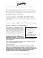
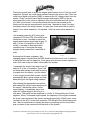
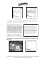
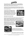
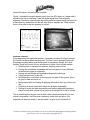
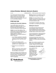
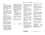
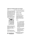
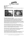
Case Study #1-92805
Type of Equipment: Tractor
Make: Agco
Model: RT-130
Symptom: No tachometer operation
Previous repairs: Instrument panel and instrument wiring harness replaced- no
change.
The Agco RT-130
The tachometer does not work.
Getting Educated About the Problem
The first step in diagnosing any problem is to verify the complaint. Next, ask
questions to get as much information as possible about the complaint. In this
case, verifying the problem was easy: when the tractor was running, the
tachometer needle stayed at zero. The problem was constant, under all
conditions. Asking technicians and salespeople involved, it turns out this tractor
has had the problem since it was new and nobody had been able to successfully
diagnose and repair it so far. So, in summary, we know that the tachometer does
not work under any circumstances and it never has.
It was also learned that the instrument panel, containing the tachometer, had
been recently replaced with no success. After the instrument panel, the
instrument wiring harness was replaced, still with no success. Since these parts
were new, it is unlikely that they are the cause of the problem. A quick visual
inspection to verify proper installation is all that is necessary.
After learning all of this, I decided to approach this tractor fresh, as if I were the
first person to attempt a diagnosis and repair of the tachometer problem. This
way I could avoid any possible preconceptions about the problem.
Getting Educated About the System(s) Involved.
I have to confess that I know little, if not nothing, about farm equipment. I do have
plenty of mechanical and electronic experience however. Since the laws of
mechanics and electricity are the same whether they are in a forklift, a car, a
Questions? Comments? Got a good example of your own? Contact the JM Equipment training department:
phone 559-233-0187 or e-mail [email protected].
tractor or anything else, I figured I have a shot at figuring this thing out. I also
know that electronic control systems on ag equipment are similar to those found
on passenger cars and forklifts, both of which I am familiar with.
All, I need to know then is the details of the specific system. Where is the best
place to turn for this information? The service manual of course. Unfortunately,
this manual was very disappointing because it was incredibly vague. It did have
wiring diagrams however and wiring diagrams are full of information on how a
system works; this is where I looked for clues.
I located the tachometer on a wiring diagram, I saw that it had a signal wire
coming from the Autotronic Control Unit (We’ll call this the ACU). This wire
originated at plug J1 of the ACU and went through a Deutsch-type connector
called CD3. The wire also branched off and went to a plug for the Electronic Lift
Control (ELC) harness.
So far, this seemed like a simple system, The ACU provides an engine speed
signal to the tachometer and the ELC. Note that I like to use the term engine
speed instead of RPM since RPM could refer to a number of things such as PTO
speed, etc. It’s always best to be as specific as possible.
Knowing that the ACU generated and engine
A Note About Electricity
speed signal, it makes sense that it must have
Remember that electricity is used to
some sort of engine speed reference to base this do two jobs in most systems:
signal on. Studying the wiring diagrams a little
1. To do work (i.e. as in a
starter circuit, relay
more, I found an engine speed sensor. It was
circuit, etc.)
obviously a magnetic, two-wire type sensor with
2. To communicate
a rotating toothed wheel since it was literally
information.
drawn that way on the diagram. These sensors
In this case, the engine speed sensor
always produce an AC voltage signal that varies
generates an electrical signal that
communicates engine speed.
in frequency and amplitude depending on the
speed of the toothed wheel. The wires from this
sensor passed through a Deutsch-type connector called CD4 and ended at the
ACU in connector J1.
Now, I hopefully had a complete picture of the system. All that was left was to
test it and determine what the problem was.
Testing the System
Now was time to test the system but where is the best place to start? Every
building project starts at the foundation and diagnosis, while not a building
project, is still no different: start at the foundation of the system. In this case, the
foundation was the engine speed sensor. It is a self-sufficient circuit that does not
use battery voltage to operate. This engine speed signal was the first thing
necessary for the ACU to make the tachometer work correctly.
Questions? Comments? Got a good example of your own? Contact the JM Equipment training department:
phone 559-233-0187 or e-mail [email protected].
There are several ways to check the engine speed sensor circuit. First is a visual
inspection. Second, we could check resistance across the sensor itself. Third, we
could use a digital multi-meter (DMM) to measure the AC voltage output from the
sensor. Finally, we could use a digital storage oscilloscope (DSO) to get an
accurate picture of the circuit in operation; this is the absolute best tool for the
job. Well, to be honest, I had no idea where this sensor was located on the
tractor and the service manual wasn’t much help. I decided to check it’s output
someplace else in the wiring harness; if it was good, there would be no need to
locate it for a visual inspection, if it was bad, I could do some more research to
find it.
I did manage locate the ACU along with
connectors CD3 and CD4; this would be an
ideal place to test. I decided to check the
engine speed sensor signal right at pins 27
and 31 of the J1 connector on the ACU.
Luckily, I was able to determine which
connector was J1 because the wiring
diagram clearly stated that it was black in
color.
Autotronic Control Unit and connectors CD3
& CD4
Knowing that this was a dynamic, fast
changing signal, I decided that the DSO would be the best tool to use. In addition
to being the best tool for diagnosis, it also gave me some nice screen captures to
use in this case study and teach others about the system.
I connected the scope’s test leads to pin 27
and pin 31 of the J1 connector. Since I did
not know what voltage levels and frequency
to expect from this sensor, I set the scope
in auto ranging mode which meant it would
automatically pick a good voltage and timebase setting for the signal being sampled.
After making the appropriate connections
and making the correct menu selections on
the scope, I started the tractor. On the
Testing the engine speed sensor signal at the ACU
scope display, I immediately saw a nice
clean AC voltage signal in the form of a
sine wave. The signal had an amplitude of 4 Volts, 2 Volts positive and 2 Volts
negative. When, I increased engine speed, the frequency of the signal increased.
As far as I was concerned, this sensor was working perfectly. What’s more, since
I tested it at the ACU, I knew that connector CD3 and all of the related wiring was
fine. I did not need locate or inspect the sensor or anything else involved; there
was no reason to be concerned with that side of the system.
Questions? Comments? Got a good example of your own? Contact the JM Equipment training department:
phone 559-233-0187 or e-mail [email protected].
Engine speed sensor signal at idle
Engine speed sensor signal at higher
RPM
There was no doubt that the ACU was seeing engine speed information but was
it sending that information to the dash unit, which contained the tachometer?
That circuit would have to be tested to find out.
Studying the wiring diagram, I saw a
single wire going from the ACU to the
tachometer. This told me that I should
probably expect to see a digital, squarewave signal that varied in frequency in
proportion to engine RPM. All I would
have to do is connect my scope to the
engine speed output at pin 17 of the
ACU J2 connector and see what I had.
A note about analog and digital signals:
Many sensors produce analog voltage
signals while computers such as the ACU
are digital devices. Units such as the ACU
often contain a conditioning circuit called
an analog to digital converter or A/D
converter. This circuit converts the analog
signal to a digital signal that computers
can recognize. Most signals coming out of
the computer are therefore digital.
I connected one scope lead to pin 17 at
the ACU J2 connector and the other
lead to engine ground. I set the scope to auto ranging made and waited for the
signal to appear. The signal I expected never appeared, I just saw a flat line at
zero Volts.
Checking the engine speed output signals from the
ACU
No engine speed signal at all from
the ACU
Questions? Comments? Got a good example of your own? Contact the JM Equipment training department:
phone 559-233-0187 or e-mail [email protected].
My first inclination was to condemn the ACU. After all, it was responsible for
creating the missing signal. I figured that the ACU was expensive though and
might take a while to get so it was best to resist my initial temptation and do a
little more testing. If the ACU was bad, I’d better prove it.
Something else about the missing engine speed output bothered me: it was at
exactly zero volts. I figured I would at least see some static voltage but there was
nothing. Past experience told me that I might have been looking at a signal circuit
that was shorted to ground.
I shut the tractor off and disconnected the J2
connector. Next I took my DMM and checked
continuity between pin 17 and ground. Sure
enough, it was zero Ohm’s. This was a direct
short to ground. But where was it? The instrument
wiring harness was new and so was the dash unit.
I remembered about the connection to the ELC
harness. I located the ELC harness connector
inside a panel next to the seat. When I
disconnected it, the short went away!
ELC harness connector
Now all I had to do was find the short in the ELC system; it was back to the wiring
diagram. Looking at the ELC wiring diagram, I noticed that the engine speed
signal wire branched off again and went to a harness connector for the
Datatronic 2 system. I figured that I’d better eliminate that as a possible problem
before proceeding with checking the ELC system. I could not find anything that
looked like the Datatronic 2 system; the tractor
apparently didn’t have it. I did find wiring for it
underneath another side panel however.
Following the wiring, I saw that it ended at a
connector, which was laying on top of a metal
bracket above the inner fender well. I pulled on
the wiring to get a look at the connector and
the short went away!
The Datatronic 2 Harness connector.
The male pins inside this connector were
exposed. When I put the connector back in the
same position on the bracket, the short came
back. This must have been the problem the entire
time.
Close-up of Datatronic 2 connector
laying on metal bracket. Not visible is a
blind nut on the bracket protruding into
the connector.
I tied the connector up and away from the bracket
and reassembled the interior of the tractor. Next I
Questions? Comments? Got a good example of your own? Contact the JM Equipment training department:
phone 559-233-0187 or e-mail [email protected].
started the tractor; the tachometer worked!
Finally, I checked the engine speed output from the ACU again so I knew what it
should be for future reference, I saw the digital signal that I had originally
expected. There are unique things about this particular digital signal that could be
a discussion by themselves but we will save that for another day. What matters
most in this case is that the problem is solved.
Digital engine speed output signal
from the ACU
The tachometer now works great.
Lessons Learned
From diagnosing this particular problem, I learned a lot about the Agco product.
Do I know everything about tractors now? Far from it and I probably never will.
Knowing everything about a particular piece of equipment though, isn’t what
matters; there is too much for any one person to know. Here is what matters:
• Realizing that no situation is hopeless, anything can be fixed.
• Having that foundation knowledge that you can apply to many different
situations and types of equipment.
• Having a good attitude and methodical diagnostic technique.
• Using the right tools for the job.
• Not jumping to conclusions or focusing on one part of the system; prove
its good or bad and move on.
• Being resourceful and finding & applying information from any source you
can.
• Collecting as much information about the problem as possible.
• Getting as much test data as possible and making diagnostic decisions
based on that data; refuse to just guess or throw parts at it until it is fixed.
This is something that anyone can do with a little training and practice. As our
industry progresses, it will become a necessity rather than an option. Our
experience is what we make it; we can make it a good one if we decide to.
Questions? Comments? Got a good example of your own? Contact the JM Equipment training department:
phone 559-233-0187 or e-mail [email protected].
Wiring Diagrams
The wiring diagrams in the Agco manual did not reproduce well, so they are not
included here. If you’d like to see these wiring diagrams, you are encouraged to
do so. Refer to the Agco RT Series service manual pages 11A01.35, 11A01.41,
and 11C01.15.
Questions? Comments? Got a good example of your own? Contact the JM Equipment training department:
phone 559-233-0187 or e-mail [email protected].