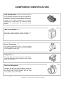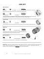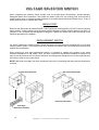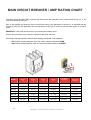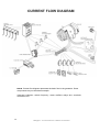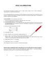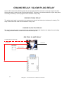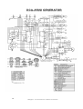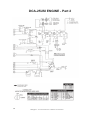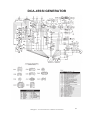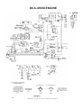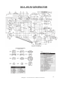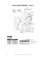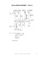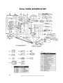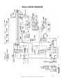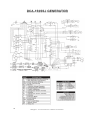
1
SERVICE MANUAL ® DCA 25-150 GENERATORS SCHEMATICS ○ TEST PROCEDURES ○ TROUBLESHOOTING DCA - 2 5 1 5 0 - CD Manual No. DCA25150CD CALIFORNIA Proposition 65 Warning: Engine exhaust and some of its constituents, and some dust created by power sanding, sawing, grinding, drilling and other construction activities contains chemicals known to the State of California to cause cancer, birth defects and other reproductive harm. Some examples of these chemicals are: • • • • Lead and lead-based paint. Crystalline silica from bricks. Cement and other masonry products. Arsenic and chromium from chemically treated lumber. Your risk from these exposures varies, depending on how often you do this type of work. To reduce your exposure to these chemicals: ALWAYS work in a well ventilated area, and work with approved safety equipment, such as dust mask that are specially designed to filter out microscopic particles. 2 Multiquip Inc. ◦ DCA Series Generators ◦ Manual No. DCA25150CD IMPORTANT! Read the operator's manual for safety instructions before you attempt to troubleshoot. Use extreme caution when troubleshooting power equipment. Never start or run power equipment inside a closed area, breathing exhaust fumes can kill. Basically, a tool is an object that enables you to take advantage of the laws of physics and mechanics in such a way that you can seriously injure yourself. This service manual is intended to provide information and procedures to safely maintain, repair and give a basic understanding of service techniques for the DCA series generators. You must be familiar with the operations of the DCA series generator before attempting to troubleshoot or make repairs. Basic operating and maintenance procedures are described in the operation and parts manual supplied with the generator. Use the supplied manual to order replacement parts. If you are missing the operation and parts manual, please contact Multiquip Inc to order a replacement or you may visit our website at www.multiquip.com For your safety and the safety of others carefully read, understand and observe all instruction described in this manual. Safety precautions should be followed at all times when servicing equipment. Consult operations manual for more safety information. THE INFORMATION CONTAINED IN THIS MANUAL IS BASED ON DCA-SERIES GENERATORS MANUFACTURED UP TO THE TIME OF PUBLICATION. MULTIQUIP INC. RESERVES THE RIGHT TO CHANGE ANY PORTION OF THIS INFORMATION WITHOUT NOTICE. Multiquip Inc. ◦ DCA Series Generators ◦ Manual No. DCA25150CD 3 CONTENTS Generator Inspection …………………………………………………………………………….…..5-6 Maintenance Inspection List …………………………………………………………………………..7 Component Identification …………………………………………………………………………..8-10 Generator Specifications ……………………………………………………………………………..11 Troubleshooting ……………………………………………………………………………………….12 Frequently Asked Questions …………………………………………………………………………13 GENERATOR COMPONENT OVERVIEW Gen-Set ………………………………………………………………………………………………...14 Rotating Rectifier / Surge Protector .……..………………………………………………………….15 Automatic Voltage Regulator ………………………………………………………………….……..16 Gen-Set Data ……………………………………………………………………………………..……17 Voltage Selector Switch …………….……………………………………………………………..18-20 Open Delta / Rheostat Data ……………..………………………..………………………………….21 Main Circuit Breaker / Amperage Rating Chart …………..…………………………………….…..22 Over Current Relay ………………………………………………………………………………..23-24 EDUCATION Index …………………………………………………………………………………………………...25 ENGINE CONTROLS Index …………………………………………………………………………………………………...36 WIRING SCHEMATICS Index …………………………………………………………………………………………………...49 GENERATOR GLOSSARY Index …………………………………………………………………………………………..……….78 4 Multiquip Inc. ◦ DCA Series Generators ◦ Manual No. DCA25150CD GENERATOR INSPECTION Before you attempt to diagnose a generator problem, check the engine to make sure that it has been serviced and is operating correctly. Perform proper maintenance and tune-up procedures before evaluating the generator. Ensure the engine remains at a stable rpm when electrical loads are applied. When servicing generators having an accurate AC/DC multi-meter is a must The first step in generator troubleshooting is to conduct a visual inspection before doing any electrical tests. Looking the generator over carefully should expose any environmental factors that might contribute to the problem. As you remove the generator control box cover and begin your inspection, look for the following: 1. Rusted or corroded connections. An oxidized connection will prevent the circuit from being completed. This applies not only to the major cables externally, but also to the electronic control devices internally. 2. Carbon flash deposits around the 120V AC and 240V AC receptacles. This will indicate whether the device that was plugged into the generator shorted out the receptacle. The device may have shorted the generator to ground and caused a carbon flash when the plug prongs touched the receptacle. 3. Signs of overheating. Discoloration and a burnt smell should be noticeable inside the generator. Look to see if the windings turned black. The winding insulative coating may vary in color from shades of reddish brown to light brown to dark brown, so try to compare the color to that of a new unit. 4. Wire insulation that is hardened from heat exposure. Fabric and plastic insulation hardens over time due to heat exposure and overheating. Long-term heating should be more uniform. A short, excessive heat cycle may have less hardening and burning on the outer perimeter and excessive heat signs toward the center or heat source. 5. Insects that have developed a community inside the generator. Their nests and debris can cause electrical shorts. Generators left out in the elements, such as for running water wells, provide a nice home for critters such as spiders, wasps, and mice. Multiquip Inc. ◦ DCA Series Generators ◦ Manual No. DCA25150CD 5 GENERATOR INSPECTION • continued • 6. Loose bolts, screws, and fasteners. This condition will either prevent full-time service or give intermittent service depending on the situation. 7. Problems in quick disconnect connectors. These are often overlooked. A quick disconnect could have one to a dozen male-female connections. These are often inside some plastic or rubber cover that prevents you from seeing any possible corrosion. In electrical troubleshooting, always unplug and plug in all connectors three times to produce a freshly scraped metallic surface for good electrical contact. If the unit works after that, soak the connectors first in vinegar for a few minutes, then in a baking soda solution. Rinse the connectors thoroughly with distilled water. This acid/base wash will remove corrosion, but not oil or grease. Blow dry thoroughly. Using an ohm meter, check for zero ohms on all connections. Spray the contacts with an electrical insulative spray before reassembling them. 8. Crimp connections: Even though they're widely used, they can become loose as the machine vibrates and lose consistent quality contact. Because dissimilar metals are in contact, a galvanic cell is set up that may result in corrosion when moisture is present. 9. Solder joints that have cracked or broken loose. This condition occurs much less frequently than crimped connections and basically results from poor-quality workmanship. 10. Worn insulation allowing wires to short. Insulation deteriorates from physical contact when wires rub together due to vibrations. Eventually, the internal wires can short to each other or to ground. 11. Crossed wires: Mistakes happen, particularly if the unit comes from another shop with unresolved issues or you receive it partially disassembled. 12. Fuses, circuit breakers, and ground fault interrupts. Check for physical damage to housing, buttons and levers. 6 Multiquip Inc. ◦ DCA Series Generators ◦ Manual No. DCA25150CD MAINTENANCE INSPECTION LIST The following is a compiled list of duties performed by service technicians, most of the tasks should be done during normal scheduled maintenance. INSPECT: Air cleaner for restrictions and contaminants - replace if necessary. Coolant concentration and level - adjust to 50 / 50 mix or as recommended by engine manufacture. Cooling system hoses for cracks and distortions - tighten clamps or repair as needed. Radiator for restrictions and corrosion. Block heater for leaks and is functioning properly, (this is an accessary on most units). For coolant, fuel and oil leaks - tighten connections or repair as needed. Belts and pulleys for cracks and wear - adjust or repair as needed. Governor and injection pump for leaks and proper operation. Turbo charger for proper clearance and free movement - as required. Fuel tank for contaminants and condensation. Fuel hoses, piping and connections for chafing and restrictions. Line trap - drain as needed. Hangers, anchors and supports for exhaust system. Exhaust for cracks and leaks. Battery charging system including alternator and external charger, if applicable (optional). Battery terminals – clean and apply anti-corrosion protectant as needed. Cable ends, wire connectors and terminals - tighten and repair as needed. Generator end for signs of heat discoloration. Panel controls and breakers for signs of heat discoloration and that they are securely mounted. All gauges for proper operation - during test run. Frequency and voltage - adjust as necessary. Complete start up and shut down sequence. Multiquip Inc. ◦ DCA Series Generators ◦ Manual No. DCA25150CD 7 COMPONENT IDENTIFICATION Components of the generator are expressed in either mechanical or electrical terms. Although distinctly separate, these two sets of terminology are frequently used interchangeably. To clarify confusion among conversation – below is the correct terminology: MECHANICAL: Rotor: The rotating part of the generator. Stator: The stationary part of the generator. ELECTRICAL: Exciter Field: Produces a magnetic field that induces AC output from the exciter armature Exciter Armature: Powers main field via rotating rectifier. Main Field: Produces a magnetic field that induces AC output from main armature. Main Armature: AC output to receptacles and terminals. GENERATOR ASSEMBLY (Gen-Set) In the operation and parts manual this component is identified as the Generator Assembly (Gen-Set). It consists of the following: Main Field Exciter Armature Rotating Rectifier Converts AC to DC. Surge Protector Is connected in parallel with the field coil and protects the rotating rectifier from excessive voltage surges produced in the field coil. Stator Frame Housing which encloses the main armature and exciter field. Main Armature Exciter Field Supplies a magnetic field to the exciter armature 8 Multiquip Inc. ◦ DCA Series Generators ◦ Manual No. DCA25150CD COMPONENT IDENTIFICATION Automatic Voltage Regulator (AVR) The Automatic Voltage Regulator (AVR) maintains a constant voltage level during load changes. AVR internal sensors regulate the configuration of the Open-Delta connections and automatically adjust the amount of DC current directed to the exciter field in order to maintain stable output voltage. Rheostat (Voltage Regulator) Is variable resistor connected directly to the AVR and is used for fine tuning output voltage. NOTE: In the operation and parts manual this component is identified as the Rheostat (when ordering parts). In the wire diagrams it is identified as the Voltage Regulator (VR). Voltage Selector Switch (SW) Is used to configure the generator coils for selected voltage output by re-configuring the internal contacts each time a voltage selection is made. NOTE: Voltage Selector Switch (SW) is not used on generators above DCA 150. Control Panel There are switches located on the control panel that should not be confused with the voltage selector switch. These switches are used to select lines to be monitored via gauges and are for monitoring purpose only. Gauges: Indicates output frequency in hertz Indicates current drawn from load Indicates output voltage Multiquip Inc. ◦ DCA Series Generators ◦ Manual No. DCA25150CD 9 COMPONENT IDENTIFICATION Over Current Relay (Thermal Overload Relay) In the operation and parts manual this component is identified as the Over Current Relay (OCR). It is connected to the main circuit breaker and it monitors current to the output terminals via the current transformers, in the event of an overload or short circuit it will electronically trip the main circuit breaker. Main Circuit Breaker (CB1) The Main Circuit Breaker (CB1) protects the generator output terminals U V W from overload. Current Transformer (CT) The Current Transformers (CT1, 2, 3) sense output current supplied by the Gen-Set and are connected to the ammeter and the OCR. Relay Unit (RY1) This relay disconnects the V-leg at the AVR and AC volt-meter when generator is operated in the 120/240 single phase setting. Twist Lock Receptacles 120/240V 50 amp twist lock receptacles, these can only be used when the selector switch is placed in the single phase 120/240 position and the main circuit breaker closed, (CS-6369). 10 Multiquip Inc. ◦ DCA Series Generators ◦ Manual No. DCA25150CD GENERATOR SPECIFICATIONS MODEL DCA25SSI DCA45SSI DCA70SSI DCA85SSJ DCA125SSI DCA150SSI DCA150SSJ Engine Model Isuzu BV-4LE2 Isuzu BU-4JJ1T Isuzu BJ-4JJ1X John Deere 4045HF285 Isuzu BJ-4HK1X Isuzu 6HK1X John Deere 6068HF285 Horse Power 34.3 67.1 97.9 126 173 240.1 197 Displacement 2179 cc 2999 cc 2999 cc 4500 cc 5193 cc 6800 cc 6800 cc Engine (RPM) No. of Cylinders 1800 RPM 4 4 4 4 4 4 4 17 gal. 26 gal. 40 gal. 40 gal. 63 gal. 74 gal. 69 gal. Fuel Consumption ••••••• ••••••• ••••••• ••••••• ••••••• ••••••• ••••••• full 3/4 1/2 1/4 1.66 1.21 0.85 0.58 Fuel Capacity load • gph load • gph load • gph load • gph gal gal gal gal 2.8 2.1 1.5 0.9 gal gal gal gal 4.1 3.1 2.2 1.4 gal gal gal gal 5.3 4.4 3.3 2.0 gal gal gal gal 7.3 5.7 4.1 2.5 gal gal gal gal 8.9 7.5 5.0 3.1 gal gal gal gal 9.0 7.1 5.2 3.0 gal gal gal gal Coolant Capacity 1.74 gal. 2.96 gal. 3.09 gal. 3.91 gal. 5.33 gal. 7.1 gal. 4.6 gal. Eng. Oil Capacity 2.25 gal. 3.83 gal. 3.96 gal. 3.88 gal. 6.1 gal. 10.6 gal. 8.19 gal. Eng. Oil Type Emissions CHEVRON • Delo 400 LE • 15W40 Interim Tier 4 Interim Tier 4 Tier 3 Tier 3 Tier 3 Tier 3 Tier 3 63 dB 65 dB 68 dB 68 dB 68 dB 69 dB 68 dB 1541 lbs 2464 lbs 3035 lbs 4107 lbs 5182 lbs 6417 lbs 5198 lbs MODEL DCA25USI DCA45USI DCA70USI DCA85USJ DCA125USI •••••••• DCA150USJ Engine Model Isuzu BV-4LE2 Isuzu BU-4JJ1T Isuzu BJ-4JJ1X John Deere 4045HF285 Isuzu BJ-4HK1X ••••••••• John Deere 6068HF285 Horse Power 34.3 67.1 97.9 126 173 ••••••••• 197 Displacement 2179 cc 2999 cc 2999 cc 4500 cc 5193 cc ••••••••• 6800 cc Sound Level • dB Full load at 23 feet Wet Weight • lbs Engine (RPM) No. of Cylinders 1800 RPM 4 4 4 4 4 ••••••••• 4 Fuel Capacity 41.7 gal 79.2 gal 103 gal 126 gal 169 gal. ••••••••• 214 gal Fuel Consumption ••••••• ••••••• ••••••• ••••••• ••••••• full 3/4 1/2 1/4 1.64 1.2 0.86 0.57 gal gal gal gal 2.7 gal 2.1 gal 1.5 gal 0.95 gal 4.1 3.1 2.1 1.3 Coolant Capacity 1.7 gal. 3.15 gal. 3.57 gal. 4.76 gal. 5.2 gal. ••••••••• 5.8 gal. Eng. Oil Capacity 2.25 gal. 3.83 gal. 3.96 gal. 3.88 gal. 6.1 gal. ••••••••• 8.19 gal. load • gph load • gph load • gph load • gph gal gal gal gal Eng. Oil Type Emissions Sound Level • dB Full load at 23 feet Wet Weight • lbs 5.3 4.3 3.1 2.0 gal gal gal gal 7.3 5.7 4.0 2.1 gal gal gal gal ••••••• 8.6 6.9 5.2 2.9 ••••••••• gal gal gal gal CHEVRON • Delo 400 LE • 15W40 Interim Tier 4 Interim Tier 4 Tier 3 Tier 3 Tier 3 ••••••••• Tier 3 59 dB 58 dB 60 dB 63 dB 65 dB ••••••••• 63 dB 2132 lbs 3499 lbs 4553 lbs 6048 lbs 7012 lbs ••••••••• 8223 lbs Multiquip Inc. ◦ DCA Series Generators ◦ Manual No. DCA25150CD 11 TROUBLESHOOTING The following troubleshooting chart was made from common calls received in the Technical Support department. If you don’t see your situation below, contact one of our Technical Support coordinators at (800) 421-1244 SYMPTOM No Voltage Output POSSIBLE PROBLEM AVR ○ (fuse, defective) AC Voltmeter ○ (check output w/ multi-meter) Breaker ○ (tripped, defective) Exciter Field ○ Loose Wiring ○ (check and repair) Rotating Rectifier ○ (defective) OCR ○ (tripped) REFERENCE PAGE NO # AVR ……………………………...... page. 16 Breaker …………………………… page. 22 Exciter Field …… ……………… page. 14 Rotating Rectifier …………………. page. 15 OCR .………………………….. …... page. 23 Low Voltage Output AVR ○ (coarse adjustment) Engine Speed ○ (1800 RPM) Rheostat ○ (fine adjustment) Surge Protector ○ (defective) Main Field Coil ○ (check and repair) High Voltage Output AVR ○ (defective) Engine Speed ○ (1800 RPM) Loose Wiring ○ (check and repair) Output Voltage Hunting AVR ○ Engine Speed ○ (1800 RPM) EGC ○ (adjustment) EGC .………………………………... page. 39 Output Voltage is not Adjustable Rheostat ○ Rheostat Voltage is Higher on One Output Leg Voltage Selector Switch ○ Voltage Selector Switch…………… page. 18 Voltage Selector Switch Hard or Impossible to Turn Voltage Selector Switch ○ (Replace it) Voltage Selector Switch…………… page. 18 Amperage Output with no Load Attached Voltage Selector Switch ○ Main Armature ○ Voltage Selector Switch…………… page. 18 Main Armature ………………...…… page. 14 Breaker ……………………………… page. 22 Main Circuit Breaker Trips Breaker ○ Load ○ (over current) OCR ○ Short Circuit ○ (check and repair) AVR ……………………………...…. page. 16 Rheostat ………………………. …. page. 21 Surge Protector ……………..……. page. 15 Gen-Set Data … ……………..……. page. 17 AVR …………………………………. page. 16 AVR …………………………………. page. 16 ………….. …………….. page. 21 OCR …………………………………. page. 23 PREVENTION Proper equipment maintenance will prevent the occurrence of most problems. As in all troubleshooting situations, when a problem does occur, an understanding of the problem and a logical process of elimination are required to identify the root cause. 12 Multiquip Inc. ◦ DCA Series Generators ◦ Manual No. DCA25150CD FREQUENTLY ASKED QUESTIONS Below is a list of common questions received in the technical support service department Why are the twist-lock 50 amp receptacles not working (not putting out power - voltage) ……..? The twist-lock 50 amp receptacles only work when the generator is set in the 1ø position they DO NOT work when the generator is set in the 3ø positions (this is normal operation). The main circuit breaker will not reset (why) …….? The Over Current Relay (OCR) has been tripped and needs to be reset before the main breaker can be reset. The OCR trips when maximum amperage capacity has been exceeded. The temperature alert indicator lamp is on, and the engine temperature is normal (is this bad) …..? If your generator has a cold weather kit installed, you will notice the ALERT LED comes on. This is not an alarm indicator. The ALERT LED is an indicator for fan operation, it will illuminate when fan turns on; fan turns on @ 180° F ahrenheit (this is normal operation). Does the generator end bearing require servicing …….? All current model generators have a NO maintenance required bearing. Older models had grease packing required as part of maintenance. I replaced the engine temp sensor but the engine still shuts down with hi temp indicator on (why)…? The engines have two types of triggers one is for gauges (sensor) and one is for engine shut down (switch). When replacing ensure you are replacing the correct part. SENSORS: have a resistance reading depending on temperature. SWITCHES: either open or close to ground depending on temperature. This rule also applies to the oil pressure sensor and switch. Multiquip Inc. ◦ DCA Series Generators ◦ Manual No. DCA25150CD 13 GEN SET Main Armature: Wires Qty Load leads - Identification 14 - (color) Black … U1, U2, U3, V1, V2, V3, W1, W2, X1, X2, Y1, Y2, Z1, Z2 These wires are AC outputs and they are connected to the selector switch. Wires Qty Open delta leads 4 Identification - (color) Black ……..… A, B, C, D These wires supply the supplementary voltage needed to maintain a steady state excitation output during the different level of loads. Wires are connected to the AVR through connector CN-1 Exciter Field: Wires Qty Excitation leads 2 - Identification (color) Black ………..… J, K These excitation leads are connected to the AVR on the same connector as the open delta leads CN-1 Main Field: Wires Qty Leads 2 Identification (color) Black leads ……..No Markings These leads are connected to DC positive & DC negative terminals on the Rotating Rectifier in conjunction with Surge Protector Exciter Armature: Wires Qty Leads 3 Identification (color) Yellow leads…… No Markings These leads are connected to the U, V, W terminals on the Rotating Rectifier. IMPORTANT: Inspect the components above with multi-meter set on Ohms Ω – measure resistance across the leads, and compare reading to the resistance chart on page 17 if reading indicates an open circuit, component may need to be replaced or sent in to get rewound. This DOES NOT apply to the Surge Protector. 14 Multiquip Inc. ◦ DCA Series Generators ◦ Manual No. DCA25150CD ROTATING RECTIFIER / SURGE PROTECTOR Rotating Rectifier: Connected to both the (main field) & (exciter armature) and is mounted on the exciter armature To properly check rectifier for continuity you must disconnect (un-solder) all leads. Set multi-meter for diode testing Place the positive lead from multi-meter on the DC Positive (+) terminal of the rectifier. Now touch the U, V and W terminals one at a time with the negative (-) lead, each contact should give a continuity reading. Reverse - negative multi-meter lead on the DC Positive (+) terminal and touch U, V and W with positive lead. This should cause the multi-meter to read Infinity. If the rectifier does not meet the above specifications – replace it. Surge Protector: Mounted - (soldered) directly on the Rotating Rectifier in conjunction with the Main Field black leads. NOTE: Isolate to test, disconnect, (un-solder) all leads. With multi-meter touching the leads, this should indicate an open circuit, if continuity or other reading is obtained – replace it. U V W DC Positive DC Negative Multiquip Inc. ◦ DCA Series Generators ◦ Manual No. DCA25150CD 15 AUTOMATIC VOLTAGE REGULATOR There are four connectors that attach to the AVR and two wires to the AVR terminals. The AVR also has three potentiometers, only one is for course adjustment the other two should NOT be touched. IMORTANT: There is no procedure for directly testing the AVR, use process of elimination. 8 amp fuse MQ part # 6978K753 Open delta leads and excitation leads connect to the AVR on this connector. DCA 25 ONLY A ~ Wire is – YELLOW B ~ Wire is – ORANGE C ~ Wire is – WHITE D ~ Wire is – GRAY J ~ Wire is – RED K ~ Wire is – BLUE DCA 45 to DCA 150 A ~ Wire is labeled ~ A B ~ Wire is labeled ~ B C ~ Wire is labeled ~ C D ~ Wire is labeled ~ D J ~ Wire is labeled ~ J K ~ Wire is labeled ~ K (wires colors are black) This connector has no outside connection and has a couple of bridge jumper wires. P1, P2 ~ Wire is WHITE and are bridged together. ℓ, K ~ Wire is WHITE and are bridged together. Wires connected here are for AVR internal sensing. Two WHITE wires from the V-Leg Relay are connected here. U ~ Wire is RED and is connected to terminal # 14 on the voltage selector switch. V ~ Wire is WHITE and is connected to V-Leg Relay (RY1) W ~ Wire is BLUE and is connected to terminal # 36 on the voltage selector switch. This potentiometer (pot) is the voltage course adjustment pot. This connects the Rheostat (VR) to the AVR. 1 ~ Wire is GRAY 3 ~ Wire is YELLOW VISUAL REMINDER: The pots are positioned similar to a backwards capital letter ‘L’ DO NOT! adjust the other two pots, these are factory pre-set. 16 Multiquip Inc. ◦ DCA Series Generators ◦ Manual No. DCA25150CD GEN-SET DATA The chart below can be used as a reference guide for measuring resistance on the Gen-Set RESISTANCE MEASURED IN OHMS Ω CROSS REFERENCE CHART Main Armature Generator Gen-Set Model # Model # DCA-25SSAI AVR Inputs Main Exciter A-B Armature Field Armature Field AC Outputs DC+ DC- UVW J+ K- 0.14 2 0.47 51 51 - Field 2 B-C C-D D-A 0.9 2.7 DCA-25SSI DB-0281 0.155 1.09 0.16 14 - 0.83 2.5 DCA-25SSI2 DF-0270 0.124 4 0.3 17.6 - 0.9 2.7 DCA-25SSIU / SSIU2 DF-0270 0.124 4 0.3 17.6 - 0.9 2.7 DCA-25USI / USI2 DF-0270 0.124 4 0.3 17.6 - 0.9 2.7 0.1074 0.143 0.143 13 13 0.5 1.5 DCA-40SSAI - DCA-40SSI DB-0501 0.082 1.46 0.21 15 - 0.74 2.22 DCA-45SSIU DB-0501 0.082 1.46 0.21 15 - 0.74 2.22 DCA-45SSIU2 / SSJU3 DB-0501 0.082 1.46 0.21 15 - 0.74 2.22 DCA-45SSIU4 DH-0480 0.099 1.33 0.137 18.8 0.78 2.15 DCA-45USI DB-0501 0.082 1.46 0.21 15 DCA-45USI2 DH-0480 0.099 1.33 0.137 18.8 0.042 0.93 0.143 12 12 0.41 1.25 0.048 1.8 0.21 15 - 0.61 1.83 DCA-60SSAI DCA-60SSI / SSI2 DB-0661 - 0.74 2.22 0.78 2.15 DCA-70SSJU / SSJU2 DB-0831 0.032 1.2 0.08 17.3 - 0.37 1.11 DCA-70SSI / SSIU DB-0831 0.032 1.2 0.08 17.3 - 0.37 1.11 DCA-70SSIU2 DH-0750 0.046 1.79 0.137 18.8 - 0.67 1.85 DCA-70USJ / USI DB-0831 0.032 1.2 0.08 17.3 - 0.37 1.11 DCA-70USI2 DH-0750 0.046 1.79 0.137 18.8 - 0.67 1.85 DCA-85SSJU / SSJU2 DB-1001 0.021 1.33 0.08 17.3 - 0.32 0.96 DCA-85USJ /USJ2 DB-1001 0.021 1.33 0.08 17.3 - 0.32 0.96 DCA-85SSK / SSM DB-1001 0.021 1.33 0.08 17.3 - 0.32 0.96 DCA-100SSJU DB-1101 0.022 1.4 0.08 17.3 - 0.32 0.97 DCA-125SSK DB-1381 0.015 1.52 0.08 17.3 - 0.28 0.84 DCA-125SSM / SSM2 DB-1381 0.015 1.52 0.08 17.3 - 0.28 0.84 DCA-125SSJU DB-1381 0.015 1.52 0.08 17.3 - 0.28 0.84 DCA-125USJ / USI DB-1381 0.015 1.52 0.08 17.3 - 0.28 0.84 DCA-150SSK / SSK2 DB-1651 0.011 1.75 0.08 17.3 - 0.27 0.82 DCA-150SSM DB-1651 0.011 1.75 0.08 17.3 - 0.27 0.82 DCA-150SSJU / SSV DB-1651 0.011 1.75 0.08 17.3 - 0.27 0.82 DCA-150SSJU2 DB-1651 0.011 1.75 0.08 17.3 - 0.27 0.82 DCA-150USJ / USJ2 DB-1651 0.011 1.75 0.08 17.3 - 0.27 0.82 Name of Part Wires Location of Wires Measuring between AC Output leads Exciter Field J&K (connected to AVR) Exciter Armature UVW (connected to rotating rectifier) Main Field DC+ DC – (connected to rotating rectifier) Main Armature 12 Load Leads 4 Open Delta Leads (AC Outputs) (connected to AVR – A,B,C,D) Multiquip Inc. ◦ DCA Series Generators ◦ Manual No. DCA25150CD U1 to X1 U2 to X2 V1 to Y1 V2 to Y2 W1 to Z1 W2 to Z2 17 VOLTAGE SELECTOR SWITCH When inspecting the selector switch visually look for burned spots, discoloration, smoke damage, damaged cables and connectors. Also rotate the switch (with unit not running) and ensure there is proper rotation with no sticking between positions or a locked switch without the ability to turn. If any of these faults are found • replace the switch. BENCH TEST Remove and disconnect all cables EXCEPT (wire jumpers & metal jumpers), DO NOT remove jumpers during testing. Test the switch using the above contact diagrams. Switch must be tested in all three (3) positions. If any contacts test the opposite of diagram • replace the switch and rewire according to the specified generator wire diagram. REPLACEMENT SWITCH On some models the voltage selector switch has been discontinued and replaced with a new style voltage selector switch. The new style will look different and comes with new installation brackets that replace the old brackets. When receiving a new style replacement switch it is required to position the jumpers in the same terminal designation as old switch. Also, the wire connectors are different therefore customers will have to cut the terminal wire connector ends from the wirings and change them to a new style that they will need in order to fit the new switch. NOTE: MQ does not supply new wire connectors since this is something that most service shops have on hand. Replacement Brackets Discontinued Brackets Discontinued Switch New Style Replacement Switch 18 Multiquip Inc. ◦ DCA Series Generators ◦ Manual No. DCA25150CD VOLTAGE SELECTOR SWITCH The internal connections between terminals on the voltage selector switch are indicated by an used are external *metal and **wire jumper connectors, see page 20 for jumper locations. 2 4 6 2 POSITION 4 6 1 2 1 2 3 4 6 3 4 5 6 5 8 7 9 12 11 13 15 Position 2: = 3 ø 480 / 277 – 7 8 9 10 – Position 4: = 3 ø 240 / 139 11 14 13 16 15 Position 6: = 1 ø 240 / 120 – 12 14 16 – 17 – 18 17 – 18 19 – 20 19 – 20 22 21 24 23 25 26 25 26 27 28 27 28 30 29 30 32 31 34 33 36 35 38 37 40 39 40 42 41 42 44 43 – 44 45 – 46 21 23 – 29 31 33 – 35 – 37 39 41 43 – 22 24 – 32 34 – 36 – 47 o o o o o o 10 DCA-25SSI DCA-45SSI DCA-60SSI DCA-70SSI DCA-70SSJ DCA-100SSJ o o o o o o DCA-100SSV DCA-125SSI DCA-125SSJ DCA-150SSI DCA-150SSJ DCA-150SSV 38 48 o o o o o o DCA-25USI DCA-45USI DCA-70USI DCA-85USI DCA-125USJ DCA-150USJ See page 20 for external jumper locations Multiquip Inc. ◦ DCA Series Generators ◦ Manual No. DCA25150CD 19 also VOLTAGE SELECTOR SWITCH * Metal Jumper Connections o o o o DCA-25SSI DCA-45SSI DCA-70SSI DCA-100SSV o o DCA-150SSV DCA-150USJ o o DCA-25USI DCA-45USI o o DCA-70USI DCA-85USJ ** Wire Jumper Connections o o o DCA-25SSI DCA-45SSI DCA-70SSI o DCA-100SSV o o DCA-25USI DCA-45USI 20 DCA-150USJ o o DCA-150SSV o o o Multiquip Inc. ◦ DCA Series Generators ◦ Manual No. DCA25150CD DCA-70USI DCA-85USJ DCA-125USJ OPEN DELTA / RHEOSTAT DATA For best results when measuring, use accurate tools that are properly calibrated. OPEN DELTA The Open Delta contacts can be used for troubleshooting. Disconnect the CN1 connector on the AVR and you can measure the resistance of the Open Delta windings at the connector. Connector Measuring Between Wires Value CN1………………………………………A & B……………..…………….(50 – 90 AC voltage) CN1………………………………………A & D……………………………(50 – 90 AC voltage) CN1………………………………………C & D……………………………(50 – 90 AC voltage) CN1………………………………………B & C………………………………….(10 AC voltage) LOCATION: CN1 connector is on AVR RHEOSTAT Symptom: AC voltage output is half the normal value and there is no response when adjusting rheostat. Disconnect the CN4 connector on the AVR and you can measure the resistance of the rheostat at the connector. The multi-meter should indicate a smooth change in resistance value while rotating the adjustment knob back and forth between min & max. Connector Measuring Between Wires Value CN4……………………………1 & 3……………………. (0 – 1000 Ohms Ω) If the Rheostat indicates open or varies from the above - it should be replaced Multiquip Inc. ◦ DCA Series Generators ◦ Manual No. DCA25150CD 21 MAIN CIRCUIT BREAKER / AMP RATING CHART This Main Circuit Breaker (CB) connects and disconnects the generator to the output terminal lugs (U, V, W) and is monitored by the OCR. 99% of the breaker trip faults are due to insufficient sizing of the generator to the load. It is essential that the unit being used for the application be sized properly to the load in order to prevent these types of nuisance faults. IMORTANT: Verify load and ensure it is not causing the breaker to trip. Proper sizing formulas can be found in operation and parts manuals. Checking continuity between contacts while tripping the CB will verify operation. o o OFF position reading between input and output contacts should be OPEN ON position reading between input and output contacts should be CLOSED Amps @ Amps @ Amps @ Amps @ MODEL 240VAC 3 Ø 480VAC 3 Ø 120VAC 1 Ø 240VAC 1 Ø DCA • 25 60 Amps 30 Amps 55.6 Amps DCA • 45 108 Amps 54 Amps DCA • 70 168 Amps DCA • 85 Circuit Breaker Trip Rating Over Current Relay Trip Set Point 27.8 Amps 60 Amps 30 Amps 100 Amps 50 Amps 110 Amps 54 Amps 84 Amps 155.5 Amps 78.8 Amps 175 Amps 84 Amps 204 Amps 102 Amps 188.9 Amps 94.9 Amps 250 Amps 102 Amps DCA • 100 241 Amps 120 Amps 222.2 Amps 111.1 Amps 250 Amps 120 Amps DCA • 125 300 Amps 150 Amps 277.8 Amps 138.9 Amps 300 Amps 150 Amps DCA • 150 361 Amps 180 Amps 333.3 Amps 166.7 Amps 400 Amps 180 Amps 22 Multiquip Inc. ◦ DCA Series Generators ◦ Manual No. DCA25150CD OVER CURRENT RELAY The Over Current Relay (OCR) is used on MQ generators and is mounted (snaps onto) a base. The base is mounted to the machine. In the event of an overload, both the circuit breaker and the OCR may trip. If the circuit breaker can not be reset, the reset button on the OCR must be pressed. The OCR is located behind the main control panel. RESETTING The reset button is located on top of the OCR and is blue in color. To reset press the button, it does not stay down when pressed it is spring loaded and will return to the up position. TESTING 1. Press the reset button 2. SLIDE the manual trip lever, this trips the OCR 3. When tripped the contacts 95-96 opens, the contacts 97-98 closes. 4. Checking continuity between contacts while tripping the OCR will verify operation. NOTE: Activating the test button while the unit is running will shunt trip the main circuit breaker. Only perform with no load on the generator. Trip Lever Multiquip Inc. ◦ DCA Series Generators ◦ Manual No. DCA25150CD 23 OVER CURRENT RELAY FACTORY SETTINGS Test Trip Lever Manual / Automatic reset – this is pre-set at factory to Manual and should not be changed. SAFETY NOTE: This dial must remain in the Man position, if placed in the Auto position relay will automatically reset after a release (trip) and could cause damages to persons or property. IMPORTANT: AMP range is preset at factory per generator model. DO NOT ADJUST. If changed main breaker may not trip. RO = Reset and Turn Off R = Only Reset AMP setting range The reset button dial is pre-set to RO If replacing, be sure to set to factory settings of original OCR 96, 97 Signaling contacts are connected to Circuit Breaker Connected to the Ammeter & Ammeter Switch 1, 3, 5 Sensing contacts are connected to Current Transformers 24 Multiquip Inc. ◦ DCA Series Generators ◦ Manual No. DCA25150CD Mounting Base EDUCATION The following information provided is for educational purpose. For more in depth training on Multiquip generators, University of Multiquip (UMQ) offers comprehensive training for salespeople or service technicians covering a complete range. Contact your local MQ rep or visit the Multiquip website at www.multiquip.com search under service and you will find more information about UMQ. INDEX EDUCATION Current Flow Diagram ……………………………………….…………………………………….…..26 Generator Theory ……………………………………………….………………………………….…..27 Heat Rise ……………………………………….………………….…………………………………....28 Insulation Class .………………………………………………………….……………………………..29 Meg-Ohm-Meter ……………………………………………………………….………………………..30 Open Delta ………………………………………………………………………………………………31 GFCI ……………………………………………………………………………………………………...32 Circuit Breaker / Short Circuit / Surge Protector …………………………………………………….33 Load Banking ……………………………………………………………………………………………34 Motor Starting Curve …………………………………………………………………………………...35 ENGINE CONTROLS Index ……………………………………………………………………………………………………..36 WIRING SCHEMATICS Index …………………………………………………………………………………………………….49 GENERATOR GLOSSARY Index …………………………………………………………………………………………………….78 Multiquip Inc. ◦ DCA Series Generators ◦ Manual No. DCA25150CD 25 CURRENT FLOW DIAGRAM NOTE: Current flow diagram represents the basic flow in the generator. Some components may not be shown example: Voltmeter, voltmeter - switch, frequency - meter, rectifiers, relays, wire - terminals, connectors, etc. 26 Multiquip Inc. ◦ DCA Series Generators ◦ Manual No. DCA25150CD GENERATOR THEORY The generator creates electricity by a series of fine wire windings inside a magnetic field, called an armature. As the armature is spun inside this magnetic field by the diesel engine, current and voltage gets generated in those windings of wire and electricity is transferred. That current and voltage will be directly proportional to the speed that the armature spins and to the strength of the magnetic field. Each complete revolution, one complete cycle of alternating current (AC) is developed. This is called a rotating armature. Most current generator designs, including MQ, utilize a rotating field type generator. The magnetic field rotates inside the main armature. The frequency of the generated voltage is dependent on the number of field poles and the speed at which the generator is operated. Frequency, measured in Hertz (Hz), is the number of complete cycles per second in alternating current direction. As current flows through the armature, there is some amount of resistance and inductive reactance. The combination of these make up what is known as: the Internal Resistance. When the load current flows, a voltage drop is developed. When a Direct Current (DC) voltage is applied to the field windings of a DC generator, current flows through the windings and sets up a steady magnetic field. This is called Field Excitation. An exciter is part of the generator package supplying direct current to the alternator field windings to magnetize the rotating poles. The exciter output may be controlled by a voltage regulator. Types of exciters include brush type with rotating commutator, static excitation or brush less generator and exciter. A regulator is an important option to consider if there is frequency or voltage sensitive equipment such as computers. Multiquip Inc. ◦ DCA Series Generators ◦ Manual No. DCA25150CD 27 HEAT RISE What is heat rise? Generator ends are rated by “Heat Rise” at a given ambient temperature and load. When current is put through a conductor the amps cause resistance and the result is heat, the temperature increase due to resistance is the “Heat Rise”. Normally, all generators are rated in degrees Celsius and at an ambient temperature of 40 degrees Celsius (104 degrees Fahrenheit). All DCA series generator ends are rated at an 85 degrees ºC “Heat Rise” at the Prime rating and 105 degrees at the standby rating. This is really robust! The next time you hear someone talk about an oversized generator end “THAT’S MQ”. Our competitors rate their generators at a much higher “Heat Rise”. For example Wacker and Magnum is anywhere from 105 ºC to 125 ºC. Baldor is rated at 125 ºC. and Generac rates theirs up to 150 ºC. This is very hot and the generators will experience reduced life. This difference may not seem like much but remember we are using degrees Celsius not Fahrenheit. When you compare temperatures in degrees Fahrenheit the differences are great. An MQ generator end rated 85 degrees ºC equates to 185 degrees ºF. A Baldor rated at 125 degrees ºC is 257 degrees ºF. That’s a difference of 72 degrees ºF. Remember that “Heat Rise” goes above and beyond ambient temperature. If this unit runs at 40 degree ºC / 104 degree ºF then the “Heat Rise” is added to the total temperature of the generator windings, increasing the total winding temperature. The “Heat Rise” of a generator end directly relates to the amount of copper in it. An alternator with less copper means higher temperature. Reduced copper means less cost. This is an area where our competitors can cut cost and sell for less. The fact is MQ uses more copper in our patented generator ends coupled with a patented excitation system results in greater motor starting capabilities, increased longevity and a great reputation. Many times competitors state that they have Class H insulation and MQ uses Class F. The class of the insulation used directly relates to the temperature that the insulation can withstand and does not relate in any way to the quality or thickness of the insulation. Class F is rated up to a 135 degrees “Heat Rise” and Class H is rated to a 155 degrees “Heat Rise”. Other companies uses class H because they have too; their generators have less copper and operate at much higher temperatures than then the DCA series generator. Understanding “Heat Rise” and “Insulation Class” really helps in comprehending the value of an MQ generator. For more on Insulation Class see next page 28 Multiquip Inc. ◦ DCA Series Generators ◦ Manual No. DCA25150CD INSULATION CLASS What is Insulation Class? Insulation systems are rated by standard NEMA (National Electrical Manufacturers Association) classifications according to maximum allowable operating temperatures: Maximum Operation Temperature Temperature Allowed Tolerance Class Allowable Temperature Rise 1.15 service factor motor 1) o o o o A 105 221 60 70 B 130 266 80 90 F 155 311 105 115 H 180 356 125 - C • Allowable Temperature Rise at full load 1.0 service factor motor 1) F C C T(oF) = [T(oC)](9/5) + 32 1) Allowable temperature rises are based upon a reference ambient temperature of 40oC. Operation temperature is reference temperature + allowable temperature rise + allowance for "hot spot" winding. Example Temperature Tolerance Class F: 40 oC + 105 oC + 10 oC = 155 oC In general, a motor should not operate with temperatures above the maximum. Each 10 oC rise above the rating may reduce the motor lifetime by one half. Temperature Tolerance Class B is the most common insulation class used on most 60 cycle US motors. Temperature Tolerance Class F is the most common for international and 50 cycle motors. Multiquip Inc. ◦ DCA Series Generators ◦ Manual No. DCA25150CD 29 MEG-OHM-METER Good Insulation Every generator winding, motor and extension cord have electric wire that is covered with some form of insulation. Electrical wire is normally copper and it is a good conductor of the electric current that powers motors. The wires insulation must be the opposite of a conductor; it should resist the current and keep it in its path along the conductor. The purpose of the insulation around a conductor is similar to that of pipe carrying water. Pressure on water from a pump causes flow along the pipe. If the pipe was to spring a leak you’d waste water and lose some water pressure. With electricity, voltage is like the pump pressure causing current to move along the copper wire. As with the flow of water in a pipe, there is resistance to flow of current but it is much less along the conductor than through its insulation. It should be noted that no insulation is perfect; meaning has infinite resistance, so some electricity does flow along the insulation or even through it to ground. The current passing through the insulation may only be a millionth of an ampere (one microampere) but it is the basis of insulation testing. A higher voltage tends to cause more current leakage through the insulation. This current leakage would become a problem if the insulation has deteriorated. All this leads us to determine “what is good insulation”. Under normal conditions “good” means a relatively high resistance to current. Or it can also be stated that a good insulation has the ability to keep a high resistance. A suitable way of measuring resistance can tell us how good the insulation is. Also if regular insulation measurements are made you can track trends towards its deterioration. Causes of Bad Insulation When generators, welders and electric motors are new the insulation should be at its highest level of resistance. During equipment use, insulation is subject to many effects which can cause it to fail. These causes can be mechanical damage, vibrations, excessive heat or cold, dirt, oil, corrosive vapors and even moisture from humidity. During the life of a conductor’s insulation all of these causes are at work in combination with electrical stresses. If a pin hole or even a crack in the insulation develops, moisture and foreign matter can penetrate the surfaces of the insulation. This provides for a low resistance path for leakage current. Once the insulation has begun to deteriorate all elements of causes tend to combine until excessive current leakage is allowed through the insulation. At times the drop in insulation resistance can be sudden, such as occurs if the equipment is flooded. Normally insulation resistance drops gradually and gives plenty of warning if checked as a preventative maintenance. Periodic checks would allow planned reconditioning prior to operation failure and the ability to remove from service if the insulation resistance became dangerously low. Equipment with no checks may not only be dangerous to touch with voltage applied but also be subject to total burn out. A failed insulator becomes a partial conductor. 30 Multiquip Inc. ◦ DCA Series Generators ◦ Manual No. DCA25150CD OPEN DELTA Why is the open delta design efficient? As copper softens it generates less power. The open delta design runs with the copper wires at 180º F, while other competitors models run with their copper wires at 220º, and some are even as bad as 300º degrees. One outstanding feature of all MQ WhisperWatt™ engine-generator packages is the patented, Denyo open-delta design alternator. Of all the hardware assembled to form a complete generator package, the AC alternator is probably the single most important albeit misunderstood component in the assembly. The MQ Power alternator is built like no other on the market. This is why MQ Power WhisperWatt™ generators offer industry leading motor starting with minimum voltage dips and quicker recoveries. The AC alternator or power generator is the device bolted to the back of the engine bell housing the rotates at engine speed to produce AC voltage and current. The alternator system is basically comprised of four component systems that work together to produce AC power. These components consist of the fixed mount stator or armature coils, the rotating field or rotor, the exciter and the automatic voltage regulator (AVR). What makes MQ better? MQ's Open Delta Coil Excitation System is design is a separately excited generator. That is, the AC voltage regulator is powered by a separate excitation winding which is placed on the stator core together with the armature windings. The excitation winding provides dedicated input power to the automatic voltage regulator, which controls the AC voltage output. The voltage regulator increases or decreases exciter current as it senses changes in output voltage and frequency, based on changes in load, thus increasing or decreasing the generator field strength. The main benefit of having a separate exciter winding is the fact that the voltage input power supplied to the voltage regulator is un-affected by the load induce fluxuations, specifically, non linear loads. And, during motor starting operations, the Denyo automatic voltage regulator switches the configuration of the internal open-delta connections to provide virtually unlimited excitation voltage, resulting in superior motor starting ability, better voltage response and voltage transient conditions. The system is so unique in design and benefits, it carries U.S. patent #4268778. Other manufacturers systems consist of a self excited generator. That means the input power supplied to the regulator is tapped from the generator output. The effectiveness of the voltage regulator in managing this event is somewhat decreased when the available AC voltage signal provided to the regulator is derived from the same AC voltage circuit being fed to the load. IF there are load induced fluxuations, precise voltage regulation is compromised. Other manufacturers' typically offer to provide their alternator with a PMG or permanent magnet generator. This is an extra cost, bolt on, alternator modification that does provide the voltage regulator with separately derived voltage input power. However, it is not as effective as MQ. And, it is extra cost. The combination of the open-delta excitation system and automatic voltage regulation which contribute to precisely control the generator output voltage and provide a stable supply of in rush current for motor starting, makes the MQ WhisperWatt™ engine-generator packages superior to all others in the industry. Multiquip Inc. ◦ DCA Series Generators ◦ Manual No. DCA25150CD 31 GFCI What is a Ground Fault Circuit Interrupter? A ground fault circuit interrupter (GFCI) is a small device that compares the amount of current flowing through the circuit. If there is a difference of more then 5 milliamps (.005 amps) the GFCI opens the circuit. What are the limits of a GFCI? There are several limitations that you should be aware of 1. A GFCI is not a tool tester. The GFCI does not have the sensitivity, detection circuits, nor the polarity, reversal features needed to perform the function of a tool tester. The GFCI makes an excellent life protection device, but a very poor tool tester. 2. A GFCI does not prevent shocks. The GFCI is only operated when a ground fault occurs. Someone using the equipment might receive a shock, but it will be a very short duration (1/30 of a second). There is a chance that a shock, even of this short duration, might cause someone to experience a fall or similar injury, but electrocution will normally be prevented. 3. A GFCI does not prevent all electrocutions. The GFCI reacts to electric current flowing from the power line to ground. It does not react to current flow between power lines. In other words, the GFCI will react to someone standing in water and comes in contact with one of the power lines. It will not protect someone who is hold the neutral power line in one hand and hot wire with the other. 4. A GFCI does not replace fuses or circuit breakers. Fuses and circuit breakers are designed to protect equipment and power lines by reacting to excessive current flow, normally in the order of 15 to 20 amps. 5. GFCI’s are designed to protect people by reacting to leakage currents to ground in the order of .005 amps. Except in the case of GFCI / circuit breaker combinations sold to be installed in building installations, they are separate devices performing separate functions. Is the ground wire still needed? The GFCI will work and perform its function with or without the tool being grounded, but the ground system is an important safety feature and should always be maintained and retested on a regular basis. Further, if a ground fault should occur, the leakage current will pass down the ground wire and trip the GFCI without the operator receiving a shock at all. So YES – please retain the ground system. How can we be sure the GFCI is working? There are two methods of testing GFCI’s. All GFCI’s sold in this country are provided with a test and reset button. During maintenance intervals simply plug a tool in to the GFCI and press the test button. The tool should turn-off and the reset button should pop-out. Depressing the reset button should restart the equipment. This is an adequate test for most applications. To measure the actual trip current of a GFCI requires a GFCI tester. The tester allows you to read the actual GFCI trip current on a meter, identifying the GFCI’s that do not operate within the required four to six milliamp range. One test that should not be performed on GFCI’s is a high load test. The GFCI contains small electronic parts that are damaged if high voltages are applied to them. DO NOT test any GFCI on a HI-POT, dialectic, or Doyle type tester. 32 Multiquip Inc. ◦ DCA Series Generators ◦ Manual No. DCA25150CD CB / SHORT CIRCUIT / SURGE PROTECTOR A circuit breaker is an automatically-operated electrical switch designed to protect an electrical circuit from damage caused by overload or short circuit. Its basic function is to detect a fault condition and, by interrupting continuity, to immediately discontinue electrical flow. Unlike a fuse, which operates once and then has to be replaced, a circuit breaker can be reset (either manually or automatically) to resume normal operation. NOTE: always place the main circuit breaker in the “OFF” position prior to starting the engine. SHORT CIRCUITS A short circuit (sometimes abbreviated to short or s/c) in an electrical circuit is one that allows a current to travel along a different path from the one originally intended. The electrical opposite of a short circuit is an "open circuit", which is an infinite resistance between two nodes. It is common to misuse "short circuit" to describe any electrical malfunction, regardless of the actual problem. Damage from short circuits can be reduced or prevented by employing fuses, circuit breakers, or other overload protection, which disconnect the power in reaction to excessive current. SURGE PROTECTORS A surge protector attempts to regulate the voltage supplied to an electric device by either blocking or by shorting to ground voltages above a safe threshold. ZENER DIODE: (older generators) A varistor is an electronic component with a “diode like” voltage characteristic. Varistors are used to protect circuits against excessive transient voltages by incorporating them into the circuit in such a way that, when triggered they shunt the current created by the high voltage away from the sensitive components. A varistor is also known as Voltage Dependent Resistor (VDR). A varistors function is to conduct significantly increased current when voltage is excessive. METAL OXIDE VARISTOR: The metal oxide varistor (MOV) contains a material, typically granular zinc oxide that conducts current (shorts) when presented with a voltage above its rated voltage. MOVs typically limit voltages to about 3 to 4 times the normal circuit voltage by diverting surge current elsewhere. MOVs have finite life expectancy and "degrade" when exposed to a few large transients, or many more smaller transients. "Degrading" is the normal failure mode. MOVs that fail shorted are so small as to violate the MOV’s "Absolute Maximum Ratings". MOVs usually are thermal fused or otherwise protected to avoid short circuits and other fire hazards. Multiquip Inc. ◦ DCA Series Generators ◦ Manual No. DCA25150CD 33 LOAD BANKING The purpose of load banking is to imitate the actual load that a power source (generator) will see during application. Load banking is a technique used to determine maximum stand by power and system performance. A load bank serves the power source and uses its energy output to test and protect that source. This method of power generation is beneficial because a real load is often unpredictable and random in value, the load applied from a load bank provides a controllable load with controls that allows an operator to incrementally step and vary the load. Load banking is a critical requirement to ensure the equipment will perform as expected when pressed into service. This applies to the name (stand by, emergency power or back up) generator. It is also recommended as part of maintenance to avoid wet stacking. Wet stacking is common when diesel engines operate for extended periods of time with little or no load applications. Wet stacking is best described as unburned fuel that accumulates in the exhaust system. A sign of wet stacking is black seepage around the exhaust connections or black exhaust from the stack after warm up. The National Fire Protection Association (NFPA) has established standards for monthly maintenance on stand-by generators. The current standard can be found on the website and referred as (NFPA 110)² which states “Generators should be exercised monthly at 30 percent of the nameplate rating or loaded to the minimum engine exhaust temperature recommended by the manufacture.” Reference: The National Fire Protection Association (NFPA) Standard for emergency and standby power systems www.nfpa.org Load banks are used after service to confirm reliability: 1. 2. 3. 4. 5. After scheduled maintenance After AVR adjustments in shop After component replacement Gen end replacements / rewinds Yearly to confirm fuel and engine cooling systems are performing correctly under full loads 34 Multiquip Inc. ◦ DCA Series Generators ◦ Manual No. DCA25150CD MOTOR STARTING CURVE STARTING CURVE (SkVA) 0 100 200 300 400 500 600 700 800 900 1000 0 DCA-150SS DCA-125SS DCA-100SS DCA-70SS DCA-45SS DCA-25SS DCA-85SS -5 VOLTAGE DIP (%) -10 -15 -20 -25 -30 -35 -40 -45 MODEL DCA25SSIU Old MSKva .4Pf 58 DCA25SS DCA45SSIU DCA150SS 63 8% 20 22 11 99 21% 36 37 17 179 22% 56 61 30 265 36% 66 70 44 231 22% 80 88 39 410 33% 100 110 68 545 32% 120 132 91 273 DCA125SSSS DCA150SSK LGR. Hp Code G 181 DCA100SS DCA125SSK/J Lit. Stby Kw 170 DCA85SS DCA100SSJU Lit. Prime Kw 140 DCA70SS DCA85SSK/M % of Increase 78 DCA45SS DCA70SSJU New MSKva .6Pf 372 Multiquip Inc. ◦ DCA Series Generators ◦ Manual No. DCA25150CD 35 ENGINE CONTROLS The DCA-25-150 Series generators are powered by four cycle engines and are manufactured by Isuzu and John Deere. The following information is to provide the service technician with a base level of knowledge on engine controls and related components. For more on engine maintenance and repairs, see engine manufacturer’s service manual. INDEX ENGINE CONTROLS Troubleshooting ……………………………………………………………………….. ………………37 ECU …………………………………………………………………………………………………..38-39 Electronic Governor System …………………………………………………………………………..40 o EGC Inspection ………………………………………………………………………………41 o EGC Calibration ……………………………………………………………………………...42 o Magnetic Pick Up …………………………………………………………………………….43 o Actuator ……………………………………………………………………………………….44 o Fuel Relay …………………………………………………………………………………….45 Crank Relay / Glow Plug Relay ……………………………………………………….. ……………..46 Feed Pump Strainer ……………………………………………………………….. …………………47 Wet Stacking ………………….…………………………………………………………………………48 WIRING SCHEMATICS Index …………………………………………………………………………………………………….49 GENERATOR GLOSSARY Index …………………………………………………………………………………………………….78 36 Multiquip Inc. ◦ DCA Series Generators ◦ Manual No. DCA25150CD TROUBLESHOOTING For more on engines see engine manufactures manual or you may contact one of our Technical Support coordinators at (800) 421-1244 SYMPTOM POSSIBLE PROBLEM INFO PAGE NO # Engine does not start No fuel ○ Air in the system ○ Water in the fuel system ○ ECU ○ (defective) Magnetic pick up ○ (defective, adjustment) Starter ○ (defective, check and repair) Battery ○ (defective, check and repair) Emergency Stop Button ○ Engine revolution is not smooth Fuel filter clogged / dirty ○ (clean or change) Air filter clogged ○ (clean or change) EGC ○ (adjustment) Surge Protector ○ (defective) Fuel Relay ○ (defective) Loose Wiring ○ (check and repair ECU ○ Magnetic pick up ○ Fuel Relay …………………..…... page. 45 Engine cranks but does not start AVR ○ Engine Speed ○ EGC ○ (out of adjustment) AVR …………………………..…... page. 16 Engine Hunting EGC Calibration …………..…… Engine start and shuts down after a few seconds ECU ○ (check fault and repair) Low Oil Pressure ○ (check and repair) Hi Engine Temp ○ (check and repair) ECU ……………. ……………....... page. 38 See engine mfr. service manual See engine mfr. service manual Excessive black smoke Wet Stack ○ Wet Stacking ………….. ……….. page. 48 Excessive white smoke Fuel ○ (air in the fuel system) See engine mfr. service manual Engine overheating Thermostat ○ (defective) Radiator ○ (clogged) Water Pump ○ (defective) Coolant Hose ○ (defective) Replenish fuel Bleed system Inspect and clean fuel system ECU …………………………….… page. 38 Magnetic pick up ……………….. page. 43 EGC Calibration …………..…… Surge Protector. …………..…… page. 41 page. 15 ECU …………………………….… page. 38 Magnetic pick up ……………….. page. 43 page. 41 See engine mfr. service manual Multiquip Inc. ◦ DCA Series Generators ◦ Manual No. DCA25150CD 37 ECU The ECU is an auto start / stop engine controller When referring to ECU in general it stands for Engine Control Unit, this unit is manufactured by Engineering Concepts Unlimited ECU The ECU auto start controller should not be confused with the actual engine manufacturers Engine Control Module (ECM). The ECM monitors engine operational inputs and directly controls outputs for fuel delivery, actuators, electronic fuel injector, etc. While the ECM does include safety shutdowns its main purpose is regulating fuel to meet emission standards. The ECM is preprogrammed with proprietary info by the engine manufacture. CONTROL SWITCH FUNCTION Control Switch AUTO position: When switch is placed in this position the ECU is connected to the auto-start contacts of the unit. The auto-start contacts are designed to connect to an automatic transfer switch (ATS) which will control the automatic start / stop of the engine through the ECU. MANUAL position: When switch is placed in this position the engine will start immediately OFF/RESET position: When switch is placed in this position the engine will not start or run, these functions are canceled. LED DEFINITIONS LOW OIL PRESSURE: Illuminates when engine oil pressure has fallen below 15 psi (103 kPa). The oil pressure is detected by the oil pressure switch and will signal ECU to shut down the engine. Do not confuse this switch with the oil pressure sensor. HIGH COOLANT TEMPERATURE: Illuminates when engine temperature has exceeded 203ºF (110ºC). The water temperature is detected by the water temperature switch and will signal ECU to shut down the engine. Do not confuse this switch with the water temperature unit. OVERCRANK SHUTDOWN: Illuminates when engine starting has failed after a pre-programmed number of attempts DCA generators are pre-set at 3 cycles with 10 second duration. OVERSPEED SHUTDOWN: Illuminates when engine is running at an unsafe speed. ENGINE RUNNING: Illuminates when engine is running at safe operating speed. 38 Multiquip Inc. ◦ DCA Series Generators ◦ Manual No. DCA25150CD EC U Wire terminals are located on the back of the LED panel BACK FRONT Below is an example of the basic wiring for the ECU, some generators may differ depending on model. Check Points o o o o o o o o o Control Switch: Battery positive voltage is present constantly on center terminal of switch. Terminal 13: This is manual power input to the ECU voltage is supplied from the control switch to this terminal. Terminal 14: This is auto power input to the ECU voltage is supplied from the control switch via remote start contacts. Terminal 6: This is power output, with control switch in manual position check for DC voltage at this terminal. Terminal 2: This is ground input. Ensure this terminal has continuity to ground. Terminal 15: This will have constant battery voltage when unit is running. Terminal 1: This receives an input signal voltage from the Magnetic Pick Up. Terminal 4: This is connected to oil pressure switch or engine manufacture engine controller. Terminal 5: This is connected to water temp switch or engine manufacture engine controller. Multiquip Inc. ◦ DCA Series Generators ◦ Manual No. DCA25150CD 39 ELECTRONIC GOVERNOR SYSTEM The Electronic Governor System consist of four components Electronic Governor Controller (EGC) Magnetic Pick Up (MPU) Actuator (ACT) Fuel Relay (FR) In order for the system to operate properly it is necessary for all the above mentioned components to operate in conjunction with each other. Should one fail, the entire governing system is affected. Electronic Governor System Operation The Electronic Governor System controls the engine governor stroke and stability during starting, variable load conditions and stopping. The Electronic Governor Controller (EGC) is able to perform this function by receiving a signal from the Magnetic Pick Up (MPU) located on the outer flywheel bell housing. This MPU sends an AC voltage signal to the EGC which will vary depending on load conditions affecting the engine r.p.m. The EGC will compare the MPU input signal to preset set-points and will react accordingly by sending a variable DC voltage signal to the Actuator (ACT) to keep the engine within manually preset engine r.p.m. parameters. The EGC receives DC voltage from the Fuel Relay (FR) which is connected directly to the accessory circuit of the DC wiring harness, typically controlled by terminal 15 on the ECU auto start controller. NOTE: EGC is a dual voltage controller and can operate in either a 12 V DC or 24 V DC system. Units produced prior to Tier 2 EPA standards may also have an “idle” function controlled by the EGC which allows the operator to warm up the engine at an “idle” speed. Units produced within the Tier 2 limits will not have this function. An EGC is normally not found in Tier 3 engines as the ECM controller controls this speed and fuel rate functions. 40 Multiquip Inc. ◦ DCA Series Generators ◦ Manual No. DCA25150CD EGC INSPECTION IMORTANT: During inspection, malfunctions may lead to other components and may require technicians to perform a complete analysis of entire system. Understanding the correct operation of the electronic governor system is essential when testing, diagnosing and performing adjustments to the EGC. TOOLS NEEDED: An accurate AC/DC Multi-Meter. Typical faults symptoms: There are three test points for the EGC: Unit cranks but will not start. Unit starts but only runs at one speed. Input Control Voltage (DC) Output Voltage to ACT (DC) Input Voltage from MPU (AC) NOTE: governor controller displayed is for educational purpose only actual controller may vary depending on generator model. The following voltages should be present on the EGC while cranking the engine PINS 1-2 (Input Control Voltage) ------------ from Fuel Relay -------- 12 volt system --------- 8V to 12V DC 1-2 (Input Control Voltage) ------------ from Fuel Relay -------- 24 volt system -------- 21V to 24V DC 4-5 (Output Actuator Voltage) --------- to Actuator ------------------------------------------------------ 4V DC 10 - 11 (Input MPU Voltage) ---------------- from Magnetic Pick Up ------------------------------------ 2.5V AC Multiquip Inc. ◦ DCA Series Generators ◦ Manual No. DCA25150CD 41 EGC CALIBRATION The following information is general and not model specific always refer to EGC manufacture documentation for calibration specifications. Prior to suspecting the EGC as the fault, service the engine to ensure fuel filter and air cleaner is not the cause for unstable engine speed or response. As the EGC and governor system ages, it is possible for the EGC to become out of calibration. TOOLS NEEDED: A fine tip standard screw driver. 1. Observe that potentiometer settings are adjustable from zero to 100%. 2. Set the small dip switch S1 to the off posostion. 3. Set the small dip switch S2 – This switch selects the point at which actuator coil current level causes the intergrator limit to to be actuated. This level is nominally 6.3 amperes for OFF position and 7.3 amperes for ON position. 4. INITIAL POTENTIOMETERS SETTINGS: GAIN ---------------- 20% I -------------------- 20% D --------------------- 30% Droop --------------- Zero 5. Start engine (no load) 6. Adjust ◦ SPEED ◦ pot as necessary to obtain specified r.p.m. 7. Adjust ◦ GAIN ◦ pot clockwise until the engine speed begins to oscillate (hunt). (If engine remains stable at 100% ◦ GAIN ◦, physically disrupt the actuator linkage by hand). With engine hunting, turn the ◦ GAIN ◦ pot counterclockwise until engine speed becomes stable. 8. Repeat step 7 for the ◦ D ◦ pot setting. 9. Repeat step 7 for the ◦ I ◦ pot setting. After setting pots, it may be necessary to re-adjust engine speed. With the engine is operating at proper speed (1800 r.p.m.), turn the EGC off (bring to idle, if equipped). When the engine speed slows down to approximately half of rated speed, turn the EGC back on, observe the overshoot. If there is a small hunt at steady state, slightly turn the ◦ I ◦ pot counterclockwise until stable. In some cases a 2 to 5 Hz overshoot may be acceptable. 42 Multiquip Inc. ◦ DCA Series Generators ◦ Manual No. DCA25150CD MAGNETIC PICK UP The Magnetic Pick Up (MPU) is an electro magnetic sensor. When a tooth from the engine flywheel passes under the tip of the sensor, electrical impulses are induced within the coil and sent to the EGC. The electrical impulse signal Hertz (Hz) is directly proportional to engine speed. The EGC uses this signal to determine the amount of DC voltage to be sent to the actuator for fuel regulation during start up and load requirements. LOCATION: Mounted in flywheel bell housing of the engine. TOOLS NEEDED: An accurate AC/DC Multi-Meter. INSPECTION • • • • • • • • Disconnect the MPU connector (isolating MPU). Using a multi-meter, test for continuity across the two pins on the connector. If an infinity reading is obtained, replace the MPU. If continuity is found, continue to next step. With MPU still disconnected, set multi-meter to AC and place both leads on the MPU connector. Crank the engine (engine will not start with MPU disconnected). With engine cranking multi-meter should read ………………………………………3 to 5 volts AC. If a low reading is obtained try adjusting MPU. ADJUSTMENT & INSTALLATION • • • • • Loosen lock nut and remove MPU from housing. Using a screw driver, rotate the flywheel slightly so that one tooth is centered in the MPU port. Reinstall MPU until it bottoms out (touching the centered tooth). Back the MPU out of the port ¼ to ½ of a turn and tighten lock nut. After adjusting re-test. Should the magnetic pick up fail any of the above checks, replace it. Multiquip Inc. ◦ DCA Series Generators ◦ Manual No. DCA25150CD 43 ACTUATOR The following information is general and not model specific always refer to Actuator manufacture documentation for specifications. The Actuator (ACT) is designed to utilize the principle of variable reluctance. It’s basically a simple, proportional, electric solenoid having a sliding armature whose magnetic force is proportional to input coil current. Balance between the force of its return spring and magnetic force, the armature glides on anti friction bearings, proving a hysteresis free linear movement. Linear motion is converted to an output shaft rotation by a bell crank. ROTARY ACTUATOR WITH ROTARY FUEL PUMP ROTARY ACTUATOR WITH LINEAR FUEL PUMP 44 Multiquip Inc. ◦ DCA Series Generators ◦ Manual No. DCA25150CD FUEL RELAY The Fuel Relay (FR) sometimes called “ice cube relay” provides the EGC its control DC voltage. Without the FR the engine governor system will be completely dead and non-operational. The FR is mounted to a base with terminals to allow its connections. Testing the FR is simple and does not require any special tooling with the exception of a multi-meter and proper battery voltage 12V DC or 24V DC depending on the system being used. The layout of contacts on the FR is shown below. View of Relay (Actual) Older generators may not have the diode in relay shown in diagram below. 1998 and newer generators have a diode across the coil to prevent back feed. Symptoms for a possible failed relay are cranking with no start. INSPECTION Remove FR from base holder. Using a multi-meter measure between the contact pins (PIN). Measurements (ohms Ω resistance) should be as follows – Relay not Energized o Continuity between ~ PIN 1 and PIN 5 (closed contacts) o Continuity between ~ PIN 2 and PIN 6 (closed contacts) o Continuity between ~ PIN 7 and PIN 8 (control coil • 12V -160 Ohms Ω / 24V-60 Ohms Ω) o Infinity between ~ PIN 3 and PIN 5 (open contacts) o Infinity between ~ PIN 4 and PIN 6 (open contacts) To measure Relay Energized apply 12V DC + to PIN 8 and Negative to PIN 7 Should the FR test normal, problem may be within the base holder. FR base is not “sealed type” and it is possible to build corrosion and dirt within. This can cause lack of path or continuity. Try cleaning the base. With FR removed spray dielectric spray cleaner and blow out with compressed air not to exceed 110 PSI. Reinstall FR and attempt to start engine, if fails continue to next step. With FR installed and while attempting to start check for DC voltage at PIN 8 + and PIN 7 - o If required DC voltage is NOT present, check for voltage at ECU terminal # 15 and any ground, no voltage indicates problem at the ECU. If required DC voltage is present and the FR is known to be good, check for voltage at EGC terminal # 1 and any ground, no voltage indicates FR base is defective and needs to be replaced. o Multiquip Inc. ◦ DCA Series Generators ◦ Manual No. DCA25150CD 45 CRANK RELAY / GLOW PLUG RELAY Used on DCA series with ISUZU engines that are equipped with ECU auto start / auto stop engine controller. Same style relay is used for both crank and glow plugs. This relay is not sealed and has an open body. Most commonly used relay in Isuzu equipped units is a Deltrol 30 amp relay. ENGINE CRANK RELAY The engine crank relay is connected to the starter motor solenoid and directly to the battery for starting. This relay is fed off the ECU crank circuit located on ECU pin # 6. ENGINE GLOW PUG RELAY The engine glow plug relay is connected to the engine glow plugs and directly to the battery for pre-heating. This relay is fed off the ECU crank circuit located on ECU pin # 6. DELTROL 30 AMP RELAY To Starter Solenoid or Glow Plugs Coil 12V DC Coil Ground Battery Positive BACK 46 Multiquip Inc. ◦ DCA Series Generators ◦ Manual No. DCA25150CD FEED PUMP STRAINER STRAINER Used on DCA45 and DCA70 series with ISUZU engine 4BG1 STRAINER • MQ Part # 1-13260047-0 WASHER / GASKET • MQ Part # 109630085-0 Symptoms of clogged strainer: Hard starting. Engine runs rough. White smoke coming out the exhaust. The feed pump strainer is located at the water separator in the banjo bolt as shown in the illustration below. Inspecting and cleaning strainer is considered part of maintenance. If strainer becomes clogged, remove from banjo bolt and clean in diesel fuel or replace if cannot be cleaned. NOTE: When replacing strainer always replace banjo bolt washer gasket. Multiquip Inc. ◦ DCA Series Generators ◦ Manual No. DCA25150CD 47 WET STACKING STRAINER Diesel engines that are operated for extended periods with light or no load applied will typically become “wetstacked“. Unless a diesel engine is operated with a sufficient load it will not reach its optimum running temperature. When the engine is not running at its optimum temperature unburned fuel can build up in the exhaust system. This can lead to fouled fuel injectors, engine valves and exhaust systems including turbo chargers and reduce overall performance. For a diesel engine to operate at peak efficiency it must be able to provide fuel and air in the proper ratio and at a high enough engine temperature for the engine to completely burn all of the fuel. Wet-stacking does not always cause permanent damage and can be alleviated if additional load is applied to relieve the condition. Usually the first sign of wet stacking is wetness in the exhaust stack that looks like oil, thus the term wet stacking. Continued operation under wet stacking conditions can cause diminished engine performance, excessive fuel consumption, and even severe engine failure because of the following conditions: Excessive unburned fuel in the exhaust system. Excessive lubricating oil consumption. Cylinder wall glazing. Poor cylinder wall lubrication and ring seating. Collection of unburned combustion particles on exhaust valves, turbo charger and exhaust manifold. WHAT IS HAPPENING? All engines are designed to work within a specified load range at specific temperatures. During combustion, the piston and liner are subject to extreme temperatures. The cylinder wall, fire rings and oil control rings and valve train are designed to work under these high temperature conditions. The fuel systems are calibrated to deliver the amount of fuel required to produce the rated horsepower. The cooling systems are designed to remove any excess heat created to keep the combustion temperatures at optimum levels. When the engine is operated with insufficient load, several things begin to happen; the high temperature created during compression ignites diesel fuel. At idle or light loads, the cooling capacity of engine exceeds the amount of heat produced creating combustion temperatures that are insufficient to burn all of the fuel. Some of this unburned fuel is left in the combustion chamber while the rest of it is pushed through the exhaust system. This mixes with the normal exhaust soot to create an oily mixture. Some of it will turn to sludge and gather on the valve stems where there is enough heat to dry it out, but not burn it, while the rest of it is pushed into the exhaust system. In addition to gathering on the valve stems, the unburned fuel begins to create a glaze on the cylinder wall and interferes with the seating of the rings to the liner. This glaze provides excess lubrication on the rings and reduces their ability to keep the combustion above the rings and the oil below the rings. The glaze actually breaks the seal created when the rings seat to the liner. If the glaze is allowed to remain for too long, loading the engine will not burn off the glaze and allow the rings to reseal themselves. In severe cases, the glaze can only be removed by disassembling the engine and re-honing the cylinder or liner. Correcting a wet stacking condition can be done by applying a constant load to the engine to burn out the excess fuel and oil and reseat the rings. If the engine can be loaded, it needs run with a sustained load until the wet stacking condition clears up. Often, this can take up to two hours of run time at minimum output of 80% rated power. The exhaust temperature should be closely monitored during this time. However, the best way to determine the load on a specific engine is to check with the engine manufacturer and use their published temperatures as a guideline. For info on load banking see page 34 48 Multiquip Inc. ◦ DCA Series Generators ◦ Manual No. DCA25150CD WIRING SCHEMATICS Due to the many different options available on the DCA-series generators, optional schematics are not included in this manual. For more information on DCA generator schematics contact the Service Technical Support Department. DCA-25SSI DCA-25SSI DCA-25USI DCA-25USI DCA-25USI DCA-45SSI DCA-45SSI DCA-45USI DCA-45USI DCA-45USI DCA-70SSI DCA-70SSI DCA-70USI DCA-70USI DCA-85SSJ DCA-85SSJ DCA-85USJ DCA-85USJ DCA-125SSI DCA-125SSI DCA-125USI DCA-125USI DCA-150SSI DCA-150SSI DCA-150SSJ DCA-150SSJ DCA-150USJ DCA-150USJ Generator ……………………………………………………………………………..50 Engine …………………………………………………………………………………51 Generator ……………………………………………………………………………..52 Engine Part 1 ………………………………………………………………………...53 Engine Part 2 ………………….……………………………………………………..54 Generator ………………………………………………………………...…………...55 Engine ………………………………………………...……………………………….56 Generator …………………………………………………………………………..…57 Engine Part 1…………………………………………………………………...…….58 Engine Part 2 ……………………………………………………...…………………59 Generator ………………………………………………………………....…………..60 Engine ……………………………………………………………………………...….61 Generator ……………………………………………………....……………………..62 Engine ……………......……………………………………………………………….63 Generator ………………………………………………………………………....…..64 Engine ................................................................................................................65 Generator …………………………………………………………………...…….…..66 Engine …………………………………………………………………………….……67 Generator …………………………………………………………………………......68 Engine ……………………………………………………………………………....…69 Generator ……………………………………………………………………..…..….70 Engine ……………………………………………………………………….……..…71 Generator ……………………………………………………………………………..72 Engine ………………………………………………………………………..……….73 Generator ……………………………………………………………………........….74 Engine …………………………………………………………………………..........75 Generator ………………………………………………………..…………...……...76 Engine .…………………………………………………………………….…………..77 GENERATOR GLOSSARY Index …………………………………………………………………………………………………..78 Multiquip Inc. ◦ DCA Series Generators ◦ Manual No. DCA25150CD 49 DCA-25SSI GENERATOR 50 Multiquip Inc. ◦ DCA Series Generators ◦ Manual No. DCA25150CD DCA-25SSI ENGINE Multiquip Inc. ◦ DCA Series Generators ◦ Manual No. DCA25150CD 51 DCA-25USI GENERATOR 52 Multiquip Inc. ◦ DCA Series Generators ◦ Manual No. DCA25150CD DCA-25USI ENGINE - Part 1 Multiquip Inc. ◦ DCA Series Generators ◦ Manual No. DCA25150CD 53 DCA-25USI ENGINE - Part 2 54 Multiquip Inc. ◦ DCA Series Generators ◦ Manual No. DCA25150CD DCA-45SSI GENERATOR Multiquip Inc. ◦ DCA Series Generators ◦ Manual No. DCA25150CD 55 DCA-45SSI ENGINE 56 Multiquip Inc. ◦ DCA Series Generators ◦ Manual No. DCA25150CD DCA-45USI GENERATOR Multiquip Inc. ◦ DCA Series Generators ◦ Manual No. DCA25150CD 57 DCA-45USI ENGINE – Part 1 58 Multiquip Inc. ◦ DCA Series Generators ◦ Manual No. DCA25150CD DCA-45USI ENGINE – Part 2 Multiquip Inc. ◦ DCA Series Generators ◦ Manual No. DCA25150CD 59 DCA-70SSI GENERATOR 60 Multiquip Inc. ◦ DCA Series Generators ◦ Manual No. DCA25150CD DCA-70SSI ENGINE Multiquip Inc. ◦ DCA Series Generators ◦ Manual No. DCA25150CD 61 DCA-70USI GENERATOR 62 Multiquip Inc. ◦ DCA Series Generators ◦ Manual No. DCA25150CD DCA-70USI ENGINE Multiquip Inc. ◦ DCA Series Generators ◦ Manual No. DCA25150CD 63 DCA-85SSJ GENERATOR 64 Multiquip Inc. ◦ DCA Series Generators ◦ Manual No. DCA25150CD DCA-85SSJ ENGINE Multiquip Inc. ◦ DCA Series Generators ◦ Manual No. DCA25150CD 65 DCA-85USJ GENERATOR 66 Multiquip Inc. ◦ DCA Series Generators ◦ Manual No. DCA25150CD DCA-85USJ ENGINE Multiquip Inc. ◦ DCA Series Generators ◦ Manual No. DCA25150CD 67 DCA-125SSI GENERATOR 68 Multiquip Inc. ◦ DCA Series Generators ◦ Manual No. DCA25150CD DCA-125SSI ENGINE Multiquip Inc. ◦ DCA Series Generators ◦ Manual No. DCA25150CD 69 DCA-125USI GENERATOR 70 Multiquip Inc. ◦ DCA Series Generators ◦ Manual No. DCA25150CD DCA-125USI ENGINE Multiquip Inc. ◦ DCA Series Generators ◦ Manual No. DCA25150CD 71 DCA-150SSI GENERATOR 72 Multiquip Inc. ◦ DCA Series Generators ◦ Manual No. DCA25150CD DCA-150SSI ENGINE Multiquip Inc. ◦ DCA Series Generators ◦ Manual No. DCA25150CD 73 DCA-150SSJ GENERATOR 74 Multiquip Inc. ◦ DCA Series Generators ◦ Manual No. DCA25150CD DCA-150SSJ ENGINE Multiquip Inc. ◦ DCA Series Generators ◦ Manual No. DCA25150CD 75 DCA-150USJ GENERATOR 76 Multiquip Inc. ◦ DCA Series Generators ◦ Manual No. DCA25150CD DCA-150USJ ENGINE Multiquip Inc. ◦ DCA Series Generators ◦ Manual No. DCA25150CD 77 GENERATOR GLOSSARY Ammeter - An instrument that measures electric current in amperes. Amperage (Amps) - The strength of a electrical current measured in amperes. Armature - That part of a generator or of an electric motor in which a current is induced by a magnetic field. The armature usually consists of a series of coils or groups of insulated conductors surrounding a core of iron. See page 8 for more information. Automatic Voltage Regulator (AVR) - Increases or decreases exciter current for a more linear voltage and frequency. See open delta page 30 for more information. Brushless Design - The purpose of the generator brush is to absorb power from the rotating armature of a generator and supply it to the stationary part of the generator. These brushes have a short life due to erosion. Multiquip’s unique brush less design calls for lower maintenance and a longer generator life. See open delta page 30 for more information. Circuit Breaker (CB) - Connects and disconnects the generator output from the output terminals. It also protects the generator from short circuits or overloads. Exciter Armature - The exciter armature or just the "exciter", generates electricity which is used for excitation of the field coil. The field coil makes the magnetic field required to generate electricity, which is used for the generators main power output. Frequency - Frequency is the number of complete cycles per second in alternating current direction. The standard unit of frequency is the hertz, abbreviated Hz. If a current completes one cycle per second, then the frequency is 1 Hz; 60 cycles per second equals 60 Hz Ground Fault Interrupters (GFI's) - These devices are designed to eliminate electrical shock hazard resulting from individuals coming in contact with a hot AC line. The circuit interrupter is designed to sense any change in circuit conditions. It is required by the NEC that all 12 volt, single phase, 15- or 20 ampere receptacle outlets that are installed outdoors or in bathrooms have ground fault interrupters connected to them Heat Rise - Is in direct relation to the longetivity of the generator. To find out why Multiquip units exceed the competition, see page 27 KVA – Kilo Volt Amp which sizes three phase loads can be converted to Kilowatts by multiplying the KVA by the power factor 0.8 NEMA - National Electrical Manufacturers Association: For more information about NEMA and their standards, visit their website at http://www.nema.org/. Ohm - A unit of electrical resistance equal to that of a conductor in which a current of one ampere is produced by a potential of one volt across its terminals. 78 Multiquip Inc. ◦ DCA Series Generators ◦ Manual No. DCA25150CD GENERATOR GLOSSARY Phase Single Phase Power (typically 120V AC or 230V AC depending on the country) is carried between two wires: live and neutral and sometimes a third ground wire for safety. The frequency of AC voltage is 50 or 60 Hz depending on the country. Single-phase power is used in very many applications, for example to power all typical home electrical appliances you use single-phase power from a normal electrical outlet at home. Three Phase Power is very common and is a more efficient use of conductors. Voltage is carried through three conductors 120° out of phase with the other two. Three-phase power provides a more efficient means of supplying large electrical loads like motors, and is used more in industrial areas. PMG - Permanent Magnetic Generator: Eliminates the excitation losses in the rotor, which otherwise typically represent 20 to 30% of the total generator losses. It also gives a lower temperature rise in the generator. Rheostat - A continuously variable electrical resistor used to regulate current. Voltage - the rate at which energy is drawn from a source that produces a flow of electricity in a circuit. Expressed in volts (V) Voltmeter - This feature serves as a convenient diagnostic tool on the jobsite. The operator can quickly tell whether or not the generator is producing the correct voltage and prevent overheating of tools and equipment. Watt – An international system unit of power equal to one joule per second, the power dissipated by a current of 1 ampere flowing across a resistance of 1 ohm. A = Amps W = Watts kW = Kilowatts vA = Volt amps kVA = Kilovolt amps 1 Ø = Single Phase 3 Ø = Three Phase V = Volts dB = Decibels Hz = Frequency (hertz) Multiquip Inc. ◦ DCA Series Generators ◦ Manual No. DCA25150CD 79 Corporate Headquarters • Multiquip Inc. 18910 Wilmington Ave. Carson, Ca. 90746 80 Multiquip Inc. ◦ DCA Series Generators ◦ Manual No. DCA25150CD