1
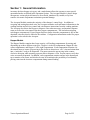
OPERATION AND SERVICE MANUAL
Table of Contents
Section 1: General Information...................................................................................................... 3
Introduction ................................................................................................................................. 3
Product Overview and Features................................................................................................... 3
Housing Module....................................................................................................................... 3
Acceptor Module...................................................................................................................... 3
Hopper Module ........................................................................................................................ 4
Specifications .............................................................................................................................. 5
Configuration ........................................................................................................................... 5
Input Power Requirements ....................................................................................................... 5
Operating Temperature Range ................................................................................................. 5
Storage Temperature Range ..................................................................................................... 5
Relative Humidity .................................................................................................................... 5
Operating Attitude.................................................................................................................... 5
Physical Dimensions ................................................................................................................ 5
Hopper Capacities .................................................................................................................... 5
Shipping Weight....................................................................................................................... 5
Section 2: Installation .................................................................................................................... 7
Unpacking.................................................................................................................................... 7
Installing the Changer.................................................................................................................. 7
Filling the Hoppers ...................................................................................................................... 7
For Your Records ........................................................................................................................ 8
Section 3: Operation .................................................................................................................... 10
Coin Acceptance........................................................................................................................ 10
Acceptor / Hopper Interface ...................................................................................................... 10
Coin Stirring and Coin Dispensing............................................................................................ 10
Full Hopper Sensing .................................................................................................................. 12
Float Mode................................................................................................................................. 12
Manual Fill Mode ...................................................................................................................... 13
Hopper Coin Counts / Status ..................................................................................................... 13
Indicator LED ............................................................................................................................ 14
Inventory Button Operation / Auto-paydown Mode / Emptying the Hopper............................ 14
Error Handling........................................................................................................................... 14
Section 4: Maintenance................................................................................................................ 16
Routine Maintenance................................................................................................................. 16
Cleaning..................................................................................................................................... 16
Removing / Replacing Individual Assemblies .......................................................................... 16
Acceptor ................................................................................................................................. 16
Hopper.................................................................................................................................... 16
Clearing Coin Jams.................................................................................................................... 16
Section 5: Troubleshooting Guide ............................................................................................... 18
Section 6: Dimensions / Exploded Views / Parts Lists................................................................ 20
Vortex Operation Manual
Page 2 of 25
Section 1: General Information
Introduction
This manual contains information on installing, operating and maintaining a Coinco Vortex
model coin changer. This manual is intended for owners, route operators and shop-level
technicians as a primary source of information. Taking time to read this manual and becoming
familiar with this information will help you obtain the best performance from your Coinco
Vortex coin changer.
Product Overview and Features
The Vortex coin changer consists of three basic modules:
• Housing module with power supply and MDB communications interface.
• Acceptor module has electronic validation capabilities based on field proven design, and uses
active sorting to route deposited coins.
• Hopper payout module has self-loading, high capacity compartments to dispense up to three
different coin types and payout sensors to ensure coin delivery.
• Coin capacity levels are programmable using Float Mode.
• Flash programmable memory is used for easy software updates that do not require a chip
change.
The Vortex coin changer supports only the MDB communication interface. See Figure 1 for a
representative MDB vending machine block diagram.
Housing Module
The Housing Module consists of the Changer Housing, Harness, and the Changer Board. The
housing contains three mounting holes for locating the changer in the vending machine, and
provides a means to securely position the other modules for proper coin routing and payout. The
harness provided meets the requirements of the NAMA MDB Protocol specification. The
changer design only supports the MDB protocol. Support for other protocols is not available.
The Changer Board provides a convenient interconnect point between the Acceptor Module and
the Hopper Module. The Changer Board contains MDB interface circuitry to meet the
requirements of the NAMA MDB Protocol specification, and power supply circuitry to convert
the unregulated MDB voltage to a nominal 12V for use in the Acceptor and Hopper Modules. A
power fail detect circuit can be monitored by the Acceptor Module to detect loss of power and
shut down operation in an orderly manner to minimize errors and loss of data.
Acceptor Module
The Acceptor Module contains circuitry to electronically validate up to 16 different coin types,
and accepted coins are actively routed to any of the three Hopper compartments or the cashbox.
Rejected coins are automatically returned to the customer. An escrow lever actuates a moveable
gate to allow bent coins or other foreign material to be easily removed. The Acceptor Module
includes a single LED indicator to provide visual feedback to the operator depending on the
current mode of operation. Three inventory buttons are available for the operator to manually
Vortex Operation Manual
Page 3 of 25
Section 1: General Information
inventory the three hopper coin types, and a mode button allows the operator to enter special
operational modes as defined in the Operation Section. The Acceptor Module’s plastic design
incorporates various physical features to divert fluids, introduced by vandals, away from
sensitive electronic components to minimize potential damage.
The Acceptor Module contains the majority of the changer’s control logic. In addition to
accepting and routing deposited coins, the Acceptor transmits credit and status information to the
vending machine and receives control and coin dispense instructions from the vending machine.
The Acceptor also directs the Hopper to dispense coins when necessary, and monitors dispense
status as well as the coin counts in the three hopper compartments. This includes monitoring
each hopper compartment’s Upper Hopper Sensor to know when the compartment is full so that
deposited coins may then be routed to the cashbox. Configuration information needed for proper
operation is also stored in the Acceptor.
Hopper Module
The Hopper Module contains three large capacity, self-loading compartments for storing and
dispensing up to three different coin types. Hopper A is the left compartment, Hopper B is the
center compartment, and Hopper C is the right compartment. Each compartment contains a bidirectional motor to rotate a payout ring in the clockwise direction to “stir” coins and orient them
into a “mini-tube” ready to be dispensed. The motor rotates the payout ring in the counterclockwise direction while actuating a payout slide to dispense a coin. Payout sensors verify that
coins are actually dispensed. In addition, each compartment contains sensors in the bottom and
top to monitor coin counts, and also has its own lid to minimize the possibility of accidentally
placing coins into the incorrect compartment during manual loading.
Vortex Operation Manual
Page 4 of 25
Section 1: General Information
Specifications
Configuration
Vortex Model VTX1 accepts US nickel, dime, quarter, and dollar coins, with the nickel routed to
Hopper B, the dime routed to Hopper A, the quarter routed to Hopper C, and the dollar routed to
the cashbox. Coins routed to a hopper are automatically routed to the cashbox when the hopper
is determined to be full.
Input Power Requirements
Minimum 20 VDC RMS (Rectified and optionally filtered) @ 1.8A.
Nominal 34 VDC unreg (Rectified and filtered)
Maximum 42.5VDC (Ripple voltage upper limit)
(Per the NAMA MDB Protocol specification.)
Operating Temperature Range
0° F to 150° F (-18° C to 65° C)
Storage Temperature Range
-22°F to 160°F (-30°C to 72°C)
Relative Humidity
20% to 95% non-condensing
Operating Attitude
Vertical ± 3°
Physical Dimensions
See Section 6
Hopper Capacities
Minimum, self-loaded: 180 US nickels, 350 US dimes, 160 US quarters
Recommended minimum to actuate low level sensors: 20 US nickels, 30 US dimes, 20 US
quarters
Shipping Weight
Approximately 4 lbs.
Vortex Operation Manual
Page 5 of 25
Section 1: General Information
Controller/Vendor Interface
VTX
MDB Coin Changer Plug
Figure 1
Vortex Operation Manual
Page 6 of 25
Section 2: Installation
Unpacking
After removing the unit from the shipping carton, inspect it for possible shipping damage. If the
unit is damaged, notify the shipping company immediately. Only the consignee (the person or
company receiving the unit) can file a claim against the carrier for shipping damage. We
recommend that you keep the original carton and packing materials to reuse if you need to
transport or ship your changer in the future.
If the coin changer is being stored or used as a spare, always keep it in its shipping carton when
not in use. This will keep it clean and offer the best protection for the unit.
Installing the Changer
1. Remove the power from the vending machine.
2. Remove the Acceptor from the Changer housing by lifting the hopper release lever (see
Figure 2) on the front of the Acceptor, and pulling the top of the Acceptor forward, away
from the Changer housing. Disconnect the Acceptor’s ribbon cable from the Changer Board.
Lift the Acceptor slightly to free the lower acceptor studs from the Changer housing. Place
the Acceptor in a clean area.
3. Remove the Hopper from the Changer housing by pulling the top of the Hopper forward,
away from the Changer housing. Disconnect the Changer Board’s ribbon cable from the top
of the Hopper. Lift the Hopper slightly to free the lower hopper studs from the Changer
housing. Place the Hopper in a clean area.
4. With the Acceptor and Hopper removed, set the mounting holes in the back of the Changer
housing over the mounting screws in the vendor, then lower the housing so the mounting
screws are in the retaining slots. Tighten snugly.
5. Load coins into the Hopper. See FILLING THE HOPPERS section.
6. Install the Hopper by inserting the lower hopper studs into the Changer housing guides.
Connect the Changer Board’s ribbon cable to the top of the Hopper. Press the top of the
Hopper into the Changer housing. Insure the ribbon cable lays behind the changer.
7. Install the Acceptor by inserting the lower acceptor studs into the Changer housing guides.
Connect the Acceptor’s ribbon cable to the Changer Board. Press the top of the Acceptor
into the Changer housing. Insure the Hopper release lever slides down into the locked
position.
8. Connect the Changer harness to the vendor.
9. Verify the vendor’s coin return mechanism is adjusted so that the Acceptor gate is fully
closed. When the vendor’s coin mechanism actuates the Acceptor escrow lever, the leading
edge of the Acceptor gate must open by at least 0.150”.
10. Apply power to the vendor. Note: every time power is applied, the changer will stir all three
payout rings to establish the presence of coins.
11. Use the inventory buttons to dispense a few coins from each hopper compartment. This
helps the changer establish an approximate coin count.
12. Test the changer with a variety of coins to ensure proper operation.
Vortex Operation Manual
Page 7 of 25
Section 2: Installation
Filling the Hoppers
Top Load
Lift the hopper release lever and pull the hopper forward. Open a single hopper lid by releasing
the black snap located at the front of each hopper. Note: This operation opens both the sensor
cover and the hopper lid. To minimize mis-loading, do not open more than one hopper lid at a
time. Fill the hopper to the desired level, snap the lid closed and repeat the process for each coin
type. Do not overfill! An indication of overfill is the need to force the hopper lid down so
that it snaps in place. When finished filling all of the hoppers, secure the sensor cover (over the
hopper lids) and press the hopper back into the changer housing. Insure the hopper release lever
is down in the locked position.
Bench Top Load
The hopper assembly may be removed by lifting the hopper release lever and pulling the hopper
assembly forward to the stops. Disconnect the hopper harness and lift the hopper assembly up
and out. Continue by following the Top Load instructions above.
Front Load
Each hopper can be loaded by inserting coins through the openings in the front of the hopper.
Acceptor Load
The Manual Fill Mode allows coin loading through the acceptor to fill the hoppers. No credit is
established in Manual Fill Mode. To enter the Manual Fill Mode, press the 25¢ inventory button
and the blue Mode button at the same time. The acceptor LED will flash an equal pattern of ON
and OFF to indicate that this mode is activated. Coins inserted through the acceptor will be
routed to the appropriate hopper. To exit the Manual Fill Mode, press the blue Mode button or
coin return lever.
For Your Records
A label indicating the changer’s model number and serial number can be found on the side of the
coin changer. Refer to the model number and serial number whenever you call your Coinco
Service Center for information or service.
The first four digits of the changer serial number indicate when the unit was built which is also
the beginning of the warranty period. The first two digits indicate the week of manufacture; the
third and fourth digits indicate the year of manufacture. For example, Serial Number
2303000123 indicates the unit was manufactured in the 23rd week of 2003.
The model number indicates special changer options, if any, such as programming to accept
certain tokens.
Vortex Operation Manual
Page 8 of 25
Section 2: Installation
7
1
5
4
3
2
6
Figure 2
Item
1
2
3
4
Description
LED Indicator
Inventory Button – Left Hopper (10¢)
Inventory Button – Center Hopper (5¢)
Inventory Button – Right Hopper (25¢)
Vortex Operation Manual
Item
5
6
7
Description
Mode Button
Hopper Release Lever
Escrow Lever
Page 9 of 25
Section 3: Operation
Coin Acceptance
Deposited coins enter the coin inlet funnel, where they are directed down a coin rail formed by
the mainplate and the escrow gate. Optical and magnetic sensors are positioned along the rail to
validate coins. When a coin reaches the end of the coin rail, it will drop into the coin reject chute
for return to the customer, unless the “accept” solenoid is energized to open the first diverter gate
to accept the coin. When the changer has no power, deposited coins are directed to the reject
chute for return to the customer. Accepted coins will go to the cashbox chute unless they are
actively routed to the hopper by energizing at least one of the remaining two solenoids. The
specific hopper is determined by which solenoid, or combination of solenoids, is energized.
The escrow lever actuates the escrow gate to serve two purposes. Pressing the escrow lever
physically opens the escrow gate to dislodge bent coins and foreign materials, allowing them to
fall into the coin reject chute. If the escrow gate opens, the movement is detected by the changer
electronics and communicated to the vending machine controller causing customer credit to be
paid back.
If coins are deposited too closely together, one or both coins may be rejected if the changer
cannot safely route them to their appropriate hopper. When any object (coin, fraud, etc) is
rejected, the changer automatically delays approximately one second before coin validation
begins again to allow the rejected object to exit the system.
Acceptor / Hopper Interface
The Acceptor and Hopper communicate with each other. The Acceptor can request coin count
and other status information from the Hopper, in addition to instructing the Hopper to stir or
dispense coins. To keep the interconnection simple and modular, the communication line is
routed through the Changer board where power supply lines are added. Multiple power and
ground lines are used to provide the maximum amount of power to the Hopper when needed. If
a power or ground conductor is broken, the system may appear operational, but performance can
suffer under high load conditions that may occur when stirring or dispensing coins.
Coin Stirring and Coin Dispensing
The Hopper PCB Assembly communicates coin count and status information to the Acceptor and
also controls the stir and payout operation under the direction of the Acceptor. The Hopper PCB
may energize the bi-directional motor to rotate the payout ring in the clockwise direction to stir
coins for approximately one second in an attempt to load a coin into the payout ring and also to
update the coin count in case coins have been deposited manually. A stir will automatically
return a payout slide to its “home” position, but will not cause a coin payout. When a hopper
stirs or dispenses a coin, the Hopper PCB monitors coin contact with the base hopper contacts to
develop an approximate coin count. This information is transmitted to the Acceptor where it is
used in an algorithm to determine the actual coin count reported to the vending machine
controller. The individual hoppers are stirred in the sequence Hopper A, Hopper B, Hopper C,
Vortex Operation Manual
Page 10 of 25
Section 3: Operation
but the hoppers are only stirred if necessary. The Acceptor requests the Hopper stir the
individual hoppers under the following conditions:
1. At power up the hoppers are each stirred twice in the sequence Hopper A, Hopper B, Hopper
C, Hopper A, Hopper B, Hopper C. The stirs are delayed approximately four seconds to
minimize power usage in case a bill acceptor is in the system and performing its initialization
which usually includes a bill stack operation that may require a significant amount of current.
Two stirs are sufficient to identify whether a hopper contains a few coins, or no coins, but up
to 10 stirs are required to identify whether a hopper contains many coins. Generally, two
stirs provide sufficient information for the changer to report coin counts that allow a vending
machine controller to enable acceptance of some larger denomination coins, and small
denomination bills. However, 10 or more stirs may be required for the Vortex to identify
coin counts sufficient to enable acceptance of larger bill denominations.
2. A hopper will be stirred periodically when the base hopper contacts detect few or no coins approximately 5 minutes after power up, or any potential customer activity (coin deposit or
coin dispense, then approximately every 60 minutes of inactivity thereafter.
3. A hopper previously empty, or low on coins, will be stirred approximately 1 minute after the
base hopper contacts suddenly detect a change in the number of coins. This is generally an
indication coins were manually loaded.
4. A hopper will be stirred upon exiting auto-paydown mode. (See the discussion on autopaydown mode later in this document.)
5. A hopper will be stirred upon exiting manual fill mode if 10 or more coins were deposited
during manual fill. (See the discussion on manual fill mode later in the document.)
A coin dispense sequence consists of the following steps as required:
1. The Hopper PCB energizes the bi-directional motor to rotate the payout ring in the counterclockwise direction and simultaneously actuate the associated payout slide
2. The payout slide moves from its “home” position to a position where it can load a coin from
the payout ring, and then back to the home position. The Hopper PCB monitors a magnet in
the payout slide to stop the slide in the home position.
3. After the motor is de-energized with the slide in the home position, the Hopper PCB
monitors one of two sense coil assemblies that are used as payout sensors. The payout
sequence is considered complete if the payout sensor detects a coin.
4. The Hopper PCB will repeat the sequence a second time if a coin payout was not detected.
Please note the Vortex will not dispense a coin on every dispense cycle. But if no coin
payout is detected, the Vortex will attempt again.
5. If the payout sensor fails to detect a coin after the second attempt, the Hopper PCB will stir
the coins. Then the Vortex repetitively attempts the “pay”, “pay”, “stir” sequence for
approximately 10 seconds, or until a coin is sensed by the payout sensor.
6. If no coin payout is detected for approximately 10 seconds, the Hopper PCB will “time out”
and inform the Acceptor that no coin was dispensed. If the Hopper’s coin dispense attempt is
not successful, the Acceptor may re-issue the coin dispense command, or the Acceptor may
request that alternate coins be dispensed.
To minimize a potential vending machine power supply conflict, stir and payout attempts may be
interrupted and then continued, approximately four seconds later, if a bill acceptor command is
detected that could cause a bill stack operation. For example, if an appropriate bill acceptor
Vortex Operation Manual
Page 11 of 25
Section 3: Operation
command was detected during the power up stir sequence, the sequence might be Hopper A,
Hopper B, delay, Hopper B, Hopper C, Hopper A, Hopper B, Hopper C, or something similar
where there is a delay before the stir sequence continues. This is normal operation and to be
expected.
The Hopper A slide may temporarily partially block the coin reject chute during a coin payout,
and the Hopper C slide may temporarily partially block the cashbox chute during a coin payout.
Consequently, if a coin payout from Hopper A is in process when another coin is deposited, the
payout will be interrupted when the slide reaches the home position for approximately two
seconds to allow the rejected coin to exit the changer. The payout operation will then continue if
necessary. If the power failure circuitry detects a power failure during a payout attempt, the
changer will automatically attempt to return the payout slide to the home position so the coin
reject chute will not be blocked during the power outage, thus allowing deposited coins to be
returned.
The Vortex changer supports the optional “Alternative Payout” MDB Level 3 command in
addition to the standard Level 2 “Dispense” command. Dispense commands are internally
buffered in the changer in case the vending machine controller issues them faster than the
changer can dispense the corresponding coins. The coin dispense sequence may not always be
highest denomination to lowest denomination because of the way the Dispense commands are
buffered, or due to various “alternative payout” sequences that may be used depending on the
Acceptor’s counts for the various coin denominations. However, the customer should receive
the proper amount of change, provided the change is available.
Due to the nature of a hopper based payout mechanism, several coins may remain in the hopper
when it reports a count of 0. This reduces potentially lengthy delays that may occur during
attempts to dispense the last few coins in a hopper. It is not unusual to see as many as 10 small
diameter coins remaining in the hopper when it is reported to be empty. Fewer larger diameter
coins remain in the hopper when the count is 0.
Full Hopper Sensing
Upper hopper magnetic sense coil assemblies are used to determine whether the three individual
hoppers are full by sensing if coins are standing up in the coin inlets at the top of the hopper. At
the time of manufacture, the Acceptor stores a “not full” value corresponding to the absence of a
coin at the sense coil assembly. When the sense coil assembly reading differs significantly from
this reference value, the hopper is considered full and future deposited coins of that type are
routed to the cashbox. If a new Hopper is installed in a changer, the Acceptor initially flags each
hopper compartment as full until 10 coins have been dispensed from the compartment. Then, the
“not full” reference value is stored. Prior to dispensing 10 coins from the compartment, if the
base hopper contacts detect few or no coins, the upper hopper magnetic sense coil reference
value will be stored immediately.
Float Mode
The operator can use the inventory buttons and mode button to enter float mode and set the
desired level of change to be individually maintained in each of the three hoppers. Once this
Vortex Operation Manual
Page 12 of 25
Section 3: Operation
mode is set, the Acceptor will route a coin into the associated hopper for every coin that has been
dispensed from that hopper. Additional deposited coins will be routed to the cashbox.
Enable float mode by simultaneously pressing the left inventory button and the mode button for
approximately 1 second, then release those buttons and simultaneously press the center and right
inventory buttons for approximately 1 second. After the left inventory and mode buttons are
pressed, the visible LED will blink at an approximate 1Hz rate, 10% duty cycle (the LED is “off
briefly, then “on” for the majority of the time), until the center and right inventory buttons are
pressed. While float mode is enabled, the visible LED will blink at a rate of approximately 1 Hz,
90% duty cycle (the LED is “on” briefly, then “off” for the majority of the time). To disable
float mode, repeat the original procedure used to enable it. The visible LED will stop blinking,
indicating float mode is no longer active. If only the left inventory and mode buttons are
pressed, the changer will automatically return to normal mode after approximately ten seconds,
and the LED will stop blinking.
While float mode is enabled, the Vortex will attempt to maintain the number of coins in all
hoppers at the level established when float mode was initially enabled. Coins will not be routed
to the respective hopper to replenish it, unless one or more coins have been dispensed from the
hopper. When initially enabled, each hopper’s float count is cleared. The Vortex attempts to
maintain the counts at zero by decrementing them for each coin dispensed, and incrementing
them for each coin deposited. As long as sufficient coins are being deposited to replenish the
hoppers, the quantity of coins in the hopper should be maintained. If coins are manually loaded
into the hopper without re-initializing float mode, the Vortex will still route coins to the
appropriate hoppers until the float count is zero, so the actual float level setting will then be
higher than when initially set. If the hopper coin level is too low when float mode is enabled, the
Vortex will route coins to the hopper until it meets the minimum acceptable level, typically 10 to
20 coins.
Float Mode is automatically cleared when a different Hopper is connected, or if the internal
configuration information is determined to be bad.
Manual Fill Mode
Manual fill mode may be used by the operator to route coins to the Hopper through the Acceptor,
without establishing any credit on the vending machine. This helps the coin changer and
vending machine keep a more accurate count of coins available for change. Press the right
inventory button and the mode button at the same time to enable manual fill mode. While
manual fill mode is active, the visible LED will blink at a rate of approximately 1 Hz, 50% duty
cycle (the LED blinks “off” and “on” for about the same amount of the time). The acceptor will
automatically enable acceptance of all hopper coins while manual fill mode is active. If no coins
are dropped for approximately 45 seconds, or if the escrow lever or mode button is pressed,
manual fill mode is exited. Depending on the type of vending machine controller, the Vortex
may reset when manual fill mode is exited.
Hopper Coin Counts / Status
Each Hopper compartment has two base hopper contacts that are used to determine an
approximate coin level in the compartment when the coins are stirred or dispensed. If the
Vortex Operation Manual
Page 13 of 25
Section 3: Operation
compartment is very low on coins, the contacts may detect coins that are manually deposited into
the hopper so the status may be sent to the Acceptor. The approximate coin level and hopper
status information is communicated to the Acceptor so that a coin count may be established and
reported to the vending machine controller.
Indicator LED
The indicator LED on the Acceptor provides visual feedback to the operator depending on the
state of the changer as follows:
1. The indicator LED is on continuously to indicate power is applied to the changer.
2. The indicator LED will blink momentarily while deposited coins are passing through the
Acceptor to indicate they are being validated.
3. When the changer is in float mode, the LED will blink at the rate defined in the Float Mode
section. (The LED is “on” briefly, then “off” for the majority of the time.)
4. When the changer is in manual fill mode, the LED will blink at the rate defined in the
Manual Fill Mode section. (The LED blinks “off” and “on” for about the same amount of
time.)
Inventory Button Operation / Auto-paydown Mode / Emptying the
Hopper
Coins may be dispensed individually from each hopper compartment by momentarily pressing
the corresponding white inventory button for the compartment. The left inventory button
corresponds to the left hopper, the center inventory button corresponds to the center hopper, and
the right inventory button corresponds to the right hopper. When an inventory button is
momentarily pressed, the changer will attempt to dispense a coin from the corresponding
compartment. The dispense sequence will automatically stop after a coin is sensed as having
been dispensed, or after an approximate 10 seconds of unsuccessful dispense activity.
Multiple coins may be dispensed by continuously pressing an inventory button until the desired
number of coins has been dispensed. If an inventory button is continuously pressed and five
coins dispensed, the changer will enter auto-paydown mode where the inventory button may be
released while the changer continues to dispense coins. Auto-paydown mode ends after
approximately 10 seconds of unsuccessful dispense activity, or after the escrow lever or mode
button is momentarily pressed.
The changer may need to be tilted backwards to help the last few coins in the hopper
compartment into the payout ring so they may be dispensed. Alternatively, the Hopper may be
turned upside down to manually empty the remaining coins.
Please note inventory button operation may be inhibited by the vending machine controller,
typically to manage power usage during a vend cycle. However, some vending machine
controllers normally inhibit inventory buttons, only enabling them when in service mode.
Error Handling
The Vortex changer is capable of detecting several types of potential internal errors, and may
continue to operate, although with reduced functionality when they occur. The following error
conditions deserve specific discussion.
Vortex Operation Manual
Page 14 of 25
Section 3: Operation
1. The changer will report a “jammed” hopper to the vending machine controller when there is
physical jam in the payout ring, the payout slide, or near the payout sensor, or if an error is
detected with the slide home sensor or the payout sensor. A jam is also reported if an
individual hopper compartment accumulates over 30 seconds of unsuccessful payout activity
while there are many coins in the compartment. A jam causes the specific compartment to be
taken off-line so the changer will no longer attempt to dispense coins from the jammed
compartment. Other compartments still capable of dispensing coins may be used to dispense
coins even though one compartment is jammed. When the source of the jam is corrected, the
operator must use the appropriate inventory button and successfully inventory a coin from
the compartment in order to clear the internal error flag and allow normal operation to
resume. The changer only attempts to dispense change from the compartment after the error
flag is cleared.
2. If the input voltage to the changer is too low for reliable operation, the changer will report to
the vending machine controller that no coins are available for change. Then coin acceptance
will be inhibited and the unit will not attempt to stir coins in the hopper, or to dispense coins.
When the input voltage is capable of supporting reliable operation, the changer will reset and
resume normal operation.
3. If the Acceptor is no longer able to communicate with the Hopper, all coin acceptance is
inhibited.
Vortex Operation Manual
Page 15 of 25
Section 4: Maintenance
Routine Maintenance
Routine maintenance will improve performance and extend the life of your Vortex changer and
reduce the need for more involved repairs. Frequency of maintenance will depend on
environment and number of transactions.
The coin changer should be kept in its original shipping carton when not in use. This will keep
the changer clean and offer the best protection for the unit.
Cleaning
The majority of your Vortex changer is manufactured from a high-quality industrial grade plastic
and should only be cleaned with a warm water and mild detergent solution.
Caution:
• Never submerge changer in water.
• Do NOT use petroleum solvents, steel wool, scouring pads, or metal brushes for
cleaning.
• Do not spray any part of the changer with any type of lubricant.
Since all coins share a common coin inlet ramp, heavy usage or a dirty environment can result in
dirt build-up in the acceptor. Clean the coin ramp by lifting the acceptor gate upward and
diagonally to the right. Hold the gate to prevent it from snapping back. Wipe the exposed coin
ramp and inner surfaces with a damp cloth. For excessively dirty units, use a damp cloth and
mild detergent. DO NOT SUBMERGE UNIT IN WATER.
Removing / Replacing Individual Assemblies
Acceptor
Remove the Acceptor from the Changer housing by lifting the hopper release lever on the front
of the Acceptor, and pulling the top of the Acceptor forward, away from the Changer housing.
Disconnect the Acceptor’s ribbon cable from the Changer Board. Lift the Acceptor slightly to
free the lower acceptor studs from the Changer housing. Place the Acceptor in a clean area.
Hopper
Remove the Hopper from the Changer housing by pulling the top of the Hopper forward, away
from the Changer housing. Disconnect the Changer Board’s ribbon cable from the top of the
Hopper. Lift the Hopper slightly to free the lower hopper studs from the Changer housing.
Place the Hopper in a clean area.
Clearing Coin Jams
To clear coins jammed in the cashbox chute, remove the Hopper. Jammed coins should then fall
out.
Vortex Operation Manual
Page 16 of 25
Section 4: Maintenance
To remove coins jammed in the Acceptor, unsnap the Front Intermediate Assembly Cover and
remove it to expose the coin path. Jammed coins should either fall out or be visible and
accessible if trapped at one of the routing gates. Snap the Front Intermediate Assembly Cover
back in place after the jam is cleared.
Perform the following procedure to remove coins jammed in a payout ring:
1. Remove all loose coins from the Hopper.
2. Remove the 2 6-32X3/8 screws from the lower front of the hopper. This allows the hopper to
tilt back allowing access to the jammed coins.
3. Note the color of the payout ring in each hopper compartment. The color identifies the coin
type for that compartment. If the payout rings are installed in the wrong compartment,
payout problems will result!
4. Clear the jammed coins. Remove the payout ring, if necessary, by pulling it out.
5. Reassemble the Hopper in the reverse order. If any payout rings were removed, be sure they
are fully seated before fastening the hopper to the payout base. Otherwise, the rings may be
jammed between the hopper and payout base, and unable to rotate. Also insure the harnesses
on the back of the Hopper are routed properly so they are not pinched between the hopper
and the payout base.
Vortex Operation Manual
Page 17 of 25
Section 5: Troubleshooting Guide
Trouble
No coin
acceptance
Possible
Cause
No Power
Verify visible LED on acceptor gate is
“on” or blinking when power is present.
VMC has coin
acceptance
disabled
VMC should be in sales mode
Hopper
No coin
acceptance or
rejects high
percentage of
good coins
Accepts coins but
gives no/or erratic
credit
Coin return
lever
Contamination
Acceptor
Acceptor
Changer Board
Hopper
New Hopper
or New
Acceptor
Accepted coins
always route to
cashbox
Procedure
Hopper
Contamination
Changer Board
Acceptor
Hopper
No payout attempt
Changer Board
Acceptor
If Hopper does not stir at power-up and
manual inventory buttons do not work
Make sure changer is mounted correctly
and coin return lever is not partially
depressed.
Remove front cover and check to see that
acceptor coin and sort path are clean and
free of foreign matter.
If still rejects good coins …
Replace with good acceptor and test
Replace with good changer board and test
Replace with good hopper and test
When the unit is powered up with a
different hopper or acceptor and coins are
Already in the unit …
When the unit is powered up with a
different hopper or acceptor and coins are
not already in the unit …
Hopper does not stir at power-up. Manual
inventory buttons do not work
Replace with good hopper and test
Remove front cover and check to see that
acceptor sort path is clean and free of
foreign matter.
Replace with good changer board and test
Replace with good acceptor and test
Hopper does not stir at power-up. Manual
inventory buttons do not work
Replace with good hopper and test
Replace with good changer board and test
Replace with good acceptor and test
Check for an incorrect coin in problem
hopper
Payout attempted
but coin is not
paid
Hopper
Vortex Operation Manual
Motor runs, slide moves up and down,
ring turns, coins move freely, but coins
still don’t pay.
Coins do not move freely when ring turns
Replace with good hopper and test
Remedy
Plug changer into vendor.
Tilt out acceptor and insure it is plugged
into changer board.
Replace MDB harness
Replace changer board
Replace Acceptor
VMC may disable coin acceptance in
service mode, sometimes when the door is
opened.
Plug changer board cable into hopper lid
board.
Reposition changer and/or vendor coin
return lever.
Follow cleaning procedure described in
manual.
Replace Acceptor
Replace Acceptor
Replace changer board
Replace hopper
Dispense 20 coins from each hopper, wait
20 sec. for upper hopper sense coil
initialization
wait 20 sec. for upper hopper sense coil
initialization
Inspect 4 position connectors on hopper lid
board. Plug in if disconnected.
Replace hopper
Follow cleaning procedure described in
manual.
Replace changer board
Replace Acceptor
Inspect 4 position connectors on hopper lid
board. Plug in if disconnected.
Replace hopper
Replace changer board
Replace Acceptor
Remove coins and eliminate incorrect
coinage. (e.g. found a nickel in dime
hopper)
Clear contamination from slide/ring area
Dislodge coins from ring.
Replace hopper
Page 18 of 25
Vortex Operation Manual
Page 19 of 25
Section 6: Dimensions / Exploded Views / Parts Lists
VORTEX DIMENSIONAL VIEWS
(All Measurements Shown in Inches)
Vortex Operation Manual
Page 20 of 25
Section 6: Dimensions / Exploded Views / Parts Lists
3
2
1
ITEM
PART #
PART DESCRIPTION
QTY.
NOTES
1
2
3
VTX1
408292
408293
408531
VORTEX CHANGER
PAYOUT ASSY, VORTEX
ACPTR ASSY,VORTEX
HSG ASSY,VORTEX
1
1
1
Includes harness and changer board
Vortex Operation Manual
Page 21 of 25
Section 6: Dimensions / Exploded Views / Parts Lists
3
2
1
ITEM
1
2
3
PART #
408531
408017
925191
407006-4
Vortex Operation Manual
PART DESCRIPTION
HSG ASSY,VORTEX
PCB ASSY,CHGR BD VORTEX
HSG,CHGR VORTEX
HRNS
QTY.
1
1
1
Page 22 of 25
Section 6: Dimensions / Exploded Views / Parts Lists
13
16
15
5 29
23
18
2x
7
22
3
2
10
9
28
6
3x
2
30
3x
1
13
19
27
11
1
26
31
24
8
33
20
12
2
30
5
15
17
25
4
28
21
14
408293 Vortex Acceptor Assembly
Vortex Operation Manual
Page 23 of 25
Section 6: Dimensions / Exploded Views / Parts Lists
ITEM
1
2
3
4
5
6
7
8
9
10
11
12
13
14
15
16
17
18
19
20
21
22
23
24
25
26
27
28
29
30
31
32
33
PART #
408293
296P6R10
345-4R5
406613-1
407615-1
407825-4
407981
408007
408016
408305
408306
408510
408511
408512
408533
408540
908845-1
923995
925159-1
925177
925180
925183
925186
925187
925188
925189
925226
925233
925288
925299
925300
925387
925561
921474
Vortex Operation Manual
PART DESCRIPTION
ACPTR ASSY,VORTEX
SCREW,6X5/8 PH PHIL TYPE25 BLK
SCREW,4X5/16 PH PHIL PLAS
COIL ASSY,SNS
PLUNGER & YOKE ASSY
TAU COIL & POT CORE
SOLENOID & 'C' FRAME ASSY
PCB ASSY,ACPTR LOGIC VORTEX
PCB ASSY,ACPTR GATE VORTEX
PLUNGR ASSY,ACPT/REJ LNK
PLUNGR ASSY,LFT/RT VORTEX
GATE ASSY,VORTEX
CVR,GATE W/LENS
MAINPLATE,W/GRATE & SRT VORTEX
CVR,FRONT INTER ASSY VORTEX
MAG WIRE & COIL ASSY
PLUG,SPRING RETENSION
LBL,ACPTR BAR CODE
LED, IR T1
LEVER,ESCROW VORTEX
GATE,ACPT/REJ SRT VORTEX
GATE,FRT/BK SRT VORTEX
CVR,ACPTR REAR VORTEX
BRKT,COIL MAINPLATE VORTEX
PLATE,DEBOUNCE VORTEX
SPRING,ACPT/REJ VORTEX
KEYPAD,VORTEX
SPRING,ESCROW VORTEX
SPRING,FRONT BACK SOLENOID
FOAM,MAINPLATE CORES
FOAM,GATE CORES
WASHER,ESCROW LEVER VORTEX
DECAL, VORTEX
TAPE, CLEAR 3/4 WIDE
QTY.
2
3
1
1
2
3
1
1
1
1
1
1
1
1
2
1
1
2
1
1
1
1
1
1
1
1
1
2
2
5
1
1
1
Page 24 of 25
Section 6: Dimensions / Exploded Views / Parts Lists
20
6
16
17
3
12 2x
13
4
2x
25
18
2
2x
26
8
23
5
9
21
6x
7
1
14
3
2x
22
24
15
3x
10
19
11
ITEM
1
2
3
4
5
6
7
8
9
10
11
12
13
14
15
16
PART #
408292
116-6R6
345-2R3
345Y4R10
406613-1
407398-7
408019-1
408297
408297-1
408297-2
408503
408509
408515
408517
408572
408988
408999-1
Vortex Operation Manual
PART DESCRIPTION
PAYOUT ASSY, VORTEX
SCREW,6-32X3/8 PH PHIL
SCREW,2X3/16 PH PHIL PLAS
SCREW,4X5/8 PH PLAS 48-2
COIL ASSY,SNS
HRNS,POWER TO LWR HOPPER
PCB ASSY,HOPPER VORTEX
SLIDE ASSY,VORTEX .25, W/ MAGNET
SLIDE ASSY,VORTEX .10, W/ MAGNET
SLIDE ASSY,VORTEX .05, W/ MAGNET
PAYOUT,BASE ASSY VORTEX
HRNS,LWR HOPPER W/TERM
HSG,VORTEX PCB W/FOAM
CVR ASSY,HOPPER VORTEX
HOPPER, W/SILICONE VORTEX
MOTOR AND GEARBOX ASSY
ASSY, VORTEX DIME DOOR & LBL
QTY.
2
2
4
2
2
1
1
1
1
1
1
1
1
1
3
1
Page 25 of 25
Section 6: Dimensions / Exploded Views / Parts Lists
ITEM
17
18
19
20
21
22
23
24
25
26
PART #
925568-1
408999-2
925568-2
408999-3
925568-3
925170
925201
925227
925328
925329
925330
925400
925546
Vortex Operation Manual
PART DESCRIPTION
LBL, VORTEX DIME DOOR
ASSY, VORTEX NICKEL DOOR & LBL
LBL, VORTEX NICKEL DOOR
ASSY, VORTEX QUARTER DOOR & LBL
LBL, VORTEX QUARTER DOOR
MOUNT,MOTOR VORTEX
CVR,PAYOUT REAR VORTEX
CONTACT,BASE HOPPER VORTEX
RING,NICKEL VORTEX
RING,DIME VORTEX
RING,QUARTER VORTEX
DIVERTER,COIN VORTEX
PIN, VORTEX HINGE
QTY.
1
1
1
1
6
1
1
1
1
1
Page 26 of 25