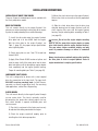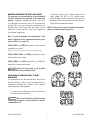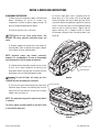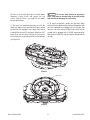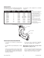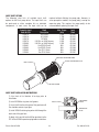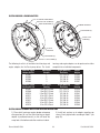
1
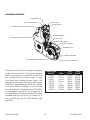
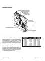
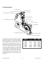
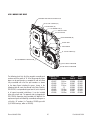
SERVICE
MANUAL
TABLE OF CONTENTS
WARNINGS AND CAUTIONS . . . . . . . . . . . . . . . . . . . . . . . . . . . . . . . . . . . . . . . . . . . . . . . . . . . . . . . . . . . . . . . . .1
MODEL IDENTIFICATION
Nomenclature for Clutch Assemblies . . . . . . . . . . . . . . . . . . . . . . . . . . . . . . . . . . . . . . . . . . . . . . . . . . . . .2
Nomenclature for Drive Plate Assemblies . . . . . . . . . . . . . . . . . . . . . . . . . . . . . . . . . . . . . . . . . . . . . . . . . .3
Nomenclature for Independent Input Assemblies . . . . . . . . . . . . . . . . . . . . . . . . . . . . . . . . . . . . . . . . . . . .4
INSTALLATION INSTRUCTIONS
Clutch Driven . . . . . . . . . . . . . . . . . . . . . . . . . . . . . . . . . . . . . . . . . . . . . . . . . . . . . . . . . . . . . . . . . . . . . . .6
Drive Plate Driven . . . . . . . . . . . . . . . . . . . . . . . . . . . . . . . . . . . . . . . . . . . . . . . . . . . . . . . . . . . . . . . . . . . .6
Independent Shaft Driven . . . . . . . . . . . . . . . . . . . . . . . . . . . . . . . . . . . . . . . . . . . . . . . . . . . . . . . . . . . . . .6
Mounting Procedure for Durst Pump Drives . . . . . . . . . . . . . . . . . . . . . . . . . . . . . . . . . . . . . . . . . . . . . . .7
Installing Hydraulic Pumps to Durst Pump Drives . . . . . . . . . . . . . . . . . . . . . . . . . . . . . . . . . . . . . . . . . . .7
REPAIR AND REBUILDING INSTRUCTIONS
Disassembly Instructions . . . . . . . . . . . . . . . . . . . . . . . . . . . . . . . . . . . . . . . . . . . . . . . . . . . . . . . . . . . .8-9
Reassembly Instructions . . . . . . . . . . . . . . . . . . . . . . . . . . . . . . . . . . . . . . . . . . . . . . . . . . . . . . . . . . .10-11
LUBRICATION AND OIL
Oil Filling Instructions . . . . . . . . . . . . . . . . . . . . . . . . . . . . . . . . . . . . . . . . . . . . . . . . . . . . . . . . . . . . . . . .12
Oil Capacity for 6 Inch Gear Centers . . . . . . . . . . . . . . . . . . . . . . . . . . . . . . . . . . . . . . . . . . . . . . . . . . . . .13
Oil Capacity for 8 Inch Gear Centers . . . . . . . . . . . . . . . . . . . . . . . . . . . . . . . . . . . . . . . . . . . . . . . . . . . . .14
Oil Capacity for 9 Inch Gear Centers . . . . . . . . . . . . . . . . . . . . . . . . . . . . . . . . . . . . . . . . . . . . . . . . . . . . .14
Oil Capacity for 10.5 Inch Gear Centers . . . . . . . . . . . . . . . . . . . . . . . . . . . . . . . . . . . . . . . . . . . . . . . . . .15
Oil Capacity for 11.3 Inch Gear Centers . . . . . . . . . . . . . . . . . . . . . . . . . . . . . . . . . . . . . . . . . . . . . . . . . .15
PART NUMBER CHARTS
1PD06 Module Pump Drive . . . . . . . . . . . . . . . . . . . . . . . . . . . . . . . . . . . . . . . . . . . . . . . . . . . . . . . . . . .16
2PD06 Module Pump Drive . . . . . . . . . . . . . . . . . . . . . . . . . . . . . . . . . . . . . . . . . . . . . . . . . . . . . . . . . . .17
3PD06 Module Pump Drive . . . . . . . . . . . . . . . . . . . . . . . . . . . . . . . . . . . . . . . . . . . . . . . . . . . . . . . . . . .18
2PD08 Module Pump Drive . . . . . . . . . . . . . . . . . . . . . . . . . . . . . . . . . . . . . . . . . . . . . . . . . . . . . . . . . . .19
3PD08 Module Pump Drive . . . . . . . . . . . . . . . . . . . . . . . . . . . . . . . . . . . . . . . . . . . . . . . . . . . . . . . . . . .20
4PD08 Module Pump Drive . . . . . . . . . . . . . . . . . . . . . . . . . . . . . . . . . . . . . . . . . . . . . . . . . . . . . . . . . . .21
4PD09 Module Pump Drive . . . . . . . . . . . . . . . . . . . . . . . . . . . . . . . . . . . . . . . . . . . . . . . . . . . . . . . . . . .22
2PD10 Module Pump Drive . . . . . . . . . . . . . . . . . . . . . . . . . . . . . . . . . . . . . . . . . . . . . . . . . . . . . . . . . . .23
3PD10 Module Pump Drive . . . . . . . . . . . . . . . . . . . . . . . . . . . . . . . . . . . . . . . . . . . . . . . . . . . . . . . . . . .24
4PD11 Module Pump Drive . . . . . . . . . . . . . . . . . . . . . . . . . . . . . . . . . . . . . . . . . . . . . . . . . . . . . . . . . . .25
Pump Spline Adapter . . . . . . . . . . . . . . . . . . . . . . . . . . . . . . . . . . . . . . . . . . . . . . . . . . . . . . . . . . . . . . . ..26
Pump Pad Adapter . . . . . . . . . . . . . . . . . . . . . . . . . . . . . . . . . . . . . . . . . . . . . . . . . . . . . . . . . . . . . . . . . .27
Input Shaft Options . . . . . . . . . . . . . . . . . . . . . . . . . . . . . . . . . . . . . . . . . . . . . . . . . . . . . . . . . . . . . . . . . .28
Clutch Housings and Engine Adapters . . . . . . . . . . . . . . . . . . . . . . . . . . . . . . . . . . . . . . . . . . . . . . . . . . .29
Drive Plate Options . . . . . . . . . . . . . . . . . . . . . . . . . . . . . . . . . . . . . . . . . . . . . . . . . . . . . . . . . . . . . . . . . .30
Clutch Options . . . . . . . . . . . . . . . . . . . . . . . . . . . . . . . . . . . . . . . . . . . . . . . . . . . . . . . . . . . . . . . . . . .31-32
GENERAL INFORMATION
Tools Needed . . . . . . . . . . . . . . . . . . . . . . . . . . . . . . . . . . . . . . . . . . . . . . . . . . . . . . . . . . . . . . . . . . . . . .33
Definitions . . . . . . . . . . . . . . . . . . . . . . . . . . . . . . . . . . . . . . . . . . . . . . . . . . . . . . . . . . . . . . . . . . . . . . . . .33
Tables . . . . . . . . . . . . . . . . . . . . . . . . . . . . . . . . . . . . . . . . . . . . . . . . . . . . . . . . . . . . . . . . . . . . . . . . . . . .33
WARRANTY . . . . . . . . . . . . . . . . . . . . . . . . . . . . . . . . . . . . . . . . . . . . . . . . . . . . . . . . . . . . . . . . . . . . . . . . . . . .34
WARNING
IMPORTANT INFORMATION
CAUTION
Please Read Carefully
Upon receipt of product, immediately inspect for any indication of rough handling or damage in transit. This includes but is not limited to:
scuffed paint, broken or damaged containers, broken or cracked housings, bent shafts, metal deformation, or shift in alignment of components.
Any evidence of damage or missing parts should be reported immediately to the carrier and a claim entered.
CAUTION
DO NOT
OPERATE
All units are shipped without oil! DO NOT OPERATE until unit has been filled to the proper level with the specified oil grade.
Failure will occur if bearings and gears are not properly lubricated. Refer to Lubrication and Oil Filling Instructions.
WARNING and
CAUTION information is supplied to the Buyer for their protection and to provide the Buyer with years
The following
of trouble free and safe operation of your REGAL-BELOIT CORPORATION product.
Read ALL instructions prior to operating pump drive. Injury to personnel or pump drive failure may be caused by improper installation,
maintenance or operation.
WARNING
• Written authorization from REGAL-BELOIT CORPORATION or its divisions/subsidiaries is required to operate or use pump
drives in man lift or people moving devices.
• Check to make certain application does not exceed the allowable load capacities published in the current catalog.
• Buyer shall be solely responsible for determining the adequacy of the product for any and all uses to which Buyer shall
apply the product. The application by Buyer shall not be subject to any implied warranty of fitness for particular purpose.
• For safety, Buyer or user should provide protective guards over all shaft extensions and any moving apparatus mounted
thereon. The user is responsible for checking all applicable safety codes in their area and providing suitable guards. Failure
to do so may result in bodily injury and/or damage to equipment.
• Hot oil can cause severe burns. Use extreme care when removing lubrication plugs and vents.
• Make certain that the power supply is disconnected before attempting to service or remove any components. Lockout the
power supply and tag it to prevent unexpected application of power.
• TORSIONAL VIBRATIONS, emanating from many modern diesel engines, can cause severe damage to power train
components, resulting in premature failure. To insure the integrity of the power transmission system, a torsional vibration
analysis should be performed and suitable vibration dampening components utilized, when indicated by the analysis. Durst
is not responsible for damage or failure resulting from diesel engine generated torsional vibrations.
CAUTION
• Lifting supports including eyebolts are to be used for vertically lifting the gearbox only and no other associated
attachments or motors.
• If the pump drive cannot be located in a clear and dry area with access to adequate cooling air supply, precautions must
be taken to avoid the ingestion of contaminates such as water, and the reduction in cooling ability due to exterior
contaminates.
• Mounting bolts should be routinely checked to ensure that the unit is firmly anchored for proper operation. Refer to Table
1 for proper torque specifications when tightening bolts.
In the event of the resale of any of the goods, in whatever form, Resellers/Buyers will include the following language in a conspicuous place and in
a conspicuous manner in a written agreement covering such sale:
The manufacturer makes no warranties or representations, express or implied, by operation of law or otherwise, as to the
merchantability or fitness for a particular purpose of the goods sold hereunder. Buyer acknowledges that it alone has determined
that the goods purchased hereunder will suitably meet the requirements of their intended use. In no event will the manufacturer be
liable for consequential, incidental or other damages. Even if the repair or replacement remedy shall be deemed to have failed of
its essential purpose under Section 2-719 of the Uniform Commercial Code, the manufacturer shall have no liability to Buyer for
consequential damages.
Resellers/Buyers agree to also include this entire document including the warnings and cautions above in a conspicuous place and in a
conspicuous manner in writing to instruct users on the safe usage of the product.
This information should be read together with all other printed information supplied by Durst.
Phone: 608-365-2563
1
Fax: 608-365-2182
MODEL IDENTIFICATION
A Durst name plate is mounted on every pump drive that
is assembled at the factory. This nameplate provides the
part number, the ratio and basic description, unit serial
number, date unit was assembled, and recommended oil
type. Do not paint over, remove, or tamper with the name-
plate, as this is the only type of identification for warranty
repairs or replacement parts.
If the Durst name plate has been destroyed the following
charts can be used to determine the model description.
NOMENCLATURE FOR CLUTCH ASSEMBLIES
1PD06
2PD06, 2PD08, 2PD10
3PD06, 3PD08, 3PD10
T
L
R
LL
1PD06 1.32I 343-CCH-LS
2PD08 1.40D 343-CCH-DDH-RS
L R
3PD06 1.29I 223-CCH-CCH-CCH-NS
T LL LR
4PD08, 4PD09, 4PD11
TL
TR
LL
LR
PILOT BEARING
1 = 3.94 Dia. (for SP214)
2 = 3.15 Dia. (for SP214)
3 = 2.83 Dia. (all others)
2PD06 1.32 D 3 4 3 - C C H - C C H - L S
Model
S = Standard Assy.
N = Non-Standard
V = Vertical / Inverted
X = Special
Ratio
I = Increaser
D = Decreaser
Phone: 608-365-2563
CLUTCH
STAND-OFF
1 = SP214 .........1.00 in.
2 = SP211 .........1.56 in.
3 = Not Available
4 = C111............1.56 in.
5 = C110............2.12 in.
CLUTCH HOUSING
1 = SAE #1
2 = SAE #2
3 = SAE #3
4PD08 1:1 111-CCV-CCH-CCH-CCH-LS
TL TR LL LR
PUMP PAD OPTIONS
A = SAE A D2 = SAE D (2 bolt)
B = SAE B E = SAE E
C = SAE C F = SAE F
D = SAE D
LR
PUMP SPLINE ADAPTER
D = SAE D, 13T-8/16
A = SAE A, 9T-16/32
F = SAE F, 15T-8/16
B = SAE B, 13T-16/32
21 = 21T-16/32
BB = SAE BB, 15T-16/32
23 = 23T-16/32
C = SAE C, 14T-12/24
27 = 27T-16/32
CC = SAE CC, 17T-12/24
2
L = Dipstick on Left Side
R = Dipstick on Right Side
N = No Dipstick
H = Pad Mounted Horizontally
V = Pad Mounted Vertically
Fax: 608-365-2182
NOMENCLATURE FOR DRIVE PLATE ASSEMBLIES
1PD06
2PD06, 2PD08, 2PD10
3PD06, 3PD08, 3PD10
T
L
R
LL
1PD06 1.32I D33-CCH-LS
2PD08 1.40D N23-CCH-DDH-RS
L R
3PD06 1.29I D22-CCH-CCH-CCH-NS
T LL LR
4PD08, 4PD09, 4PD11
TL
LL
LR
ENGINE ADAPTER
HOUSING
1 = SAE #1
2 = SAE #2
3 = SAE #3
4 = SAE #4
TR
LR
4PD08 1:1 D11-CCV-CCH-CCH-CCH-LS
TL TR LL LR
D = With Drive Plate
N = No Drive Plate/
Shaft ONLY
WITH DRIVE PLATE
1 = SAE 14
2 = SAE 11.5
3 = SAE 10
4 = SAE 8
NO DRIVE PLATE
1 = 29T-12/24 Shaft
2 = 20T-10/20 Shaft
3 = 15T-8/16 Shaft
4 = 2.50 Dia. Keyed Shaft
5 = 2.25 Dia. Keyed Shaft
2PD06 1.32 D D 1 1 - C C H - C C H - L S
Model
S = Standard Assy.
N = Non-Standard
V = Vertical / Inverted
X = Special
Ratio
I = Increaser
D = Decreaser
PUMP PAD OPTIONS
A = SAE A
B = SAE B
C = SAE C
D = SAE D
D2 = SAE D (2 bolt)
E = SAE E
F = SAE F
Phone: 608-365-2563
L = Dipstick on Left Side
R = Dipstick on Right Side
N = No Dipstick
PUMP SPLINE ADAPTER
D = SAE D, 13T-8/16
A = SAE A, 9T-16/32
F = SAE F, 15T-8/16
B = SAE B, 13T-16/32
21 = 21T-16/32
BB = SAE BB, 15T-16/32
23 = 23T-16/32
C = SAE C, 14T-12/24
27 = 27T-16/32
CC = SAE CC, 17T-12/24
3
H = Pad Mounted Horizontally
V = Pad Mounted Vertically
Fax: 608-365-2182
NOMENCLATURE FOR INDEPENDENT INPUT ASSEMBLIES
1PD06
2PD06, 2PD08, 2PD10
3PD06, 3PD08, 3PD10
T
L
R
LL
1PD06 1.32I 003-CCH-LS
2PD08 1.40D 001-CCH-DDH-RS
L R
3PD06 1.29I 002-CCH-CCH-CCH-NS
T LL LR
4PD08, 4PD09, 4PD11
TL
TR
LL
LR
INDEPENDENT INPUT
001 = 1810 Companion
002 = 1610 Companion
003 = 2.50 Dia. Keyed Shaft
004 = 2.25 Dia. Keyed Shaft
005 = 29T-12/24 Shaft
006 = 20T-10/20 Shaft
007 = 15T-8/16 Shaft
008 = Special Shaft
4PD08 1:1 007-CCV-CCH-CCH-CCH-LS
TL TR LL LR
2PD06 1.32 D 0 0 3 - C C H - C C H - L S
Model
S = Standard Assy.
N = Non-Standard
V = Vertical / Inverted
X = Special
Ratio
I = Increaser
D = Decreaser
PUMP PAD OPTIONS
A = SAE A
B = SAE B
C = SAE C
D = SAE D
D2 = SAE D (2 bolt)
E = SAE E
F = SAE F
Phone: 608-365-2563
LR
L = Dipstick on Left Side
R = Dipstick on Right Side
N = No Dipstick
PUMP SPLINE ADAPTER
A = SAE A, 9T-16/32
B = SAE B, 13T-16/32
BB = SAE BB, 15T-16/32
C = SAE C, 14T-12/24
CC = SAE CC, 17T-12/24
D = SAE D, 13T-8/16
F = SAE F, 15T-8/16
21 = 21T-16/32
23 = 23T-16/32
27 = 27T-16/32
H = Pad Mounted Horizontally
V = Pad Mounted Vertically
4
Fax: 608-365-2182
ABOUT YOUR NEW DURST PUMP DRIVE
The New Durst pump drives incorporate some of the
features from both the previous Terrell and Hub City
designs as well as many new and simplistic features.
The Durst pump drive now incorporates class 10 spur
gears that run on heavy duty ball bearings. Because ball
bearings do not require shimming the assembly of a pump
drive is drastically simplified. This also allows for the
bearing to be contained within the housing halves. The key
feature about this is that any adapter can be changed out
without disturbing the gears or bearings in the gear box.
This also allows for the box to be split to service gears and
bearings without having to remove the adapters.
SPLINES
The Durst pump drives have a 29T-12/24 internal spline
on the gears. This allows for a spline adapter to be used
on any SAE pump shaft. Because the pump shaft is no
longer integral with the gear, if the pump is changed or
replaced, a new gear is not required. A 29T-12/24 spline
significantly reduces wear on both the gears and spline
adapters.
INPUT SHAFT
The input shaft of the Durst pump drive is integral with the
input gear through a 29T-12/24 spline. The input shaft is
contained within the gear box and allows the drive plate or
torsional coupling to be free on the input shaft, which
reduces misalignment stresses from the engine flywheel
and the gear box. Due to the modular design of the
gear box the input shaft can be removed and/or replaced
without disturbing the internal workings of the gear box.
DRIVE PLATE
The Durst pump drive now uses a four disk drive plate.
By using 4 thin disks the drive plate becomes slightly
wider and increases the rating. Thin disks are much more
flexible and when multiple disks are put together they
absorb more engine vibrations than a single thick disk. As
mentioned in the Input Shaft section the drive plate is no
longer captured on the input shaft, instead it is able to
automatically adjust if any engine flywheel misalignment
occurs. These changes result in smoother operation and
longer gear box life.
OIL CIRCULATION
Extensive testing was done on each Durst pump drive gear
box to optimize the quantity of oil in each box at each ratio.
The new Durst pump drives no longer have the need
for Iso-Lube ports. Instead the Durst pump drives have
special oil port locations and oil directing ribs that causes
the oil to flow into the pump pad area, lubricating the
spline adapters and bearings without the need for external
pumps. Oil volume is critical to make this feature work and
the oil level should be checked frequently.
PUMP PADS
The Durst pump pads have been simplified and no longer
contain the bearing cup. Pump pads can now be removed
without disrupting the internal workings and alignment of
the bearings and gears inside the gear box. As mentioned
above the Durst pump pads no longer feature the Iso-Lube
ports. Oil flows into the pump pad area and then patented
cast in recesses causes the oil to flow across the spline for
wet spline operation.
Phone: 608-365-2563
5
Fax: 608-365-2182
INSTALLATION INSTRUCTIONS
INSTALLATION OF DURST PUMP DRIVES
There are 3 types of standard inputs that are available with
the Durst pump drive models.
3) Mount the clutch drive ring to the engine flywheel.
Refer to the clutch service manual for the proper bolt
torques.
DRIVE PLATE DRIVEN
This unit mounts directly to the engine flywheel. Use
extreme care when mounting the drive plate to the engine
flywheel to avoid preloading the crankshaft bearings.
4) Slide the clutch drive plates into the drive ring
and pilot bearing into the engine flywheel, until the
clutch housing fully seats with the engine flywheel
housing. Torque mounting bolts according to Table 1
(see page 33).
1) Install the drive plate onto the engine flywheel,
drive plate hub is to face AWAY from the engine.
Bolt the drive plate to the engine flywheel, see
Table 1 (page 33) for proper torque specifications
when tightening bolts.
2) Check drive plate run out. Total TIR should not
exceed 0.008".
3) Apply Silver Streak #200S to external splines and
slide the input shaft of the pump drive into the drive
plate hub splines until the pump drive engine adapter
seats completely into the engine flywheel housing.
Torque all mounting bolts per Table 1 (see page 33).
Do not use the engine adapter mounting
bolts to seat the pump drive engine adapter or pump
drive clutch housing onto the engine flywheel housing.
This may reduce engine crankshaft endplay and may
result in premature damage or failure of crankshaft
bearings.
CAUTION
Always check engine crankshaft endplay after installing
the drive plate or clutch to engine flywheel. Refer to
engine manufacturer’s endplay specifications.
INDEPENDENT SHAFT DRIVEN
This unit is designed to be driven with a short coupled
drive line connection to the input shaft. The input shaft
WILL NOT accept any overhung loads (i.e. Belt Sheaves,
sprockets, or severely angled drive lines). For over-hung
load applications, contact Durst Engineering.
CLUTCH DRIVEN
This unit mounts directly to the engine flywheel through
an over center clutch. The clutch is primarily used for
disconnecting the pump drive during engine start up.
Each clutch includes a separate installation parts and
service manual.
1) The clutch is not preset at the factory and can only
be adjusted after being mounted to the engine.
2) Check the engine crankshaft endplay prior to
installing the clutch driven pump drive.
Phone: 608-365-2563
6
Fax: 608-365-2182
MOUNTING PROCEDURES FOR DURST PUMP DRIVES
The pump drive is to be supported on a rigid foundation
using the mounting holes provided in the pump drive
housing. Inadequate mounting foundation may result
in misalignment or excessive stress on the pump drive
housing. This can cause undue noise, overheating, and
possible failure. Durst pump drive gear boxes can be
mounted in several positions to be more adaptive to
the customer’s application.
2) Align the splines of the hydraulic pump to the
spline adapter. DO NOT use the hydraulic pump
mounting bolts to seat the hydraulic pump onto the
pump pad. Refer to the hydraulic pump manufactures
specification for proper bolt torques.
NOTE: O-rings must be replaced anytime the hydraulic
pumps are removed from the gear box.
Note: To prevent loosening and misalignment, bolts
must be tightened to the recommended torques specs
shown in Table 1 (see page 33).
2PD06, 2PD08, and 2PD10 pump drives can be mounted
horizontally or vertically.
Refer to arrows that are cast into the housings for mounting direction.
1PD06, 3PD06, 3PD08, and 3PD10 pump drives can be
mounted normal or inverted.
4PD08, 4PD09, and 4PD11 pump drives can ONLY be
mounted in the normal orientation.
Failure to mount boxes in the specified
orientations will cause premature failure!
CAUTION
INSTALLATION OF HYDRAULIC PUMPS TO DURST
PUMP DRIVES
The pump pads on the Durst pump drives offer two or
four bolt mountings, which can be mounted vertically or
horizontally to provide the customer a wide range of
hydraulic pump mounting options.
1) Lubricate the included o-ring with oil and install it
onto the hydraulic pump pilot.
Due to an internal oil lubrication system
do NOT apply any grease, or spline lubricant as this will
contaminate the oil.
CAUTION
Phone: 608-365-2563
7
Fax: 608-365-2182
REPAIR & REBUILDING INSTRUCTIONS
6) Once the input drive shaft is removed, place the
pump drive on a flat surface with the pump pads
facing up. Remove the two (2) dowel pins and all the
cap screws before attempting to separate the housing
halves. Use the cap screws in the threaded separating
holes to split the housing halves. Slightly tap the
output housing with a wooden mallet to release
the bearings and gears from the bearing bores (see
Figure B).
DISASSEMBLY INSTRUCTIONS
1) Make certain that the power supply is disconnected
before attempting to service or remove any
components. Lockout the power supply and tag it to
prevent unexpected application of power.
2) Drain oil while the unit is still warm.
Hot oil can cause severe burns. Use
extreme care when removing lubrication plugs and
vents!
WARNING
3) Properly support the pump drive and remove all
retaining bolts from the pump drive engine adapter,
then remove all frame mounting bolts.
NOTE: Hydraulic pumps may remain connected,
however it is recommended, for ease of disassembly
and cleaning parts, that the pumps be removed.
4) If replacing the pump pads, remove the cap screws
or nuts. Use a large screwdriver to evenly pry the
pump pads loose of the gear box. Be careful to lift the
pump pads evenly to avoid damaging the pilot.
EXPANSION PLUG
RETAINING RING
Figure A
To avoid oil leaks, all o-rings are to be
replaced any time the pump pad is removed.
CAUTION
5) To access the input shaft retaining ring, remove the
expansion plug. Remove the retaining ring from the
input drive shaft and slide the shaft out of the engine
adapter side (see Figure A).
SEPARATING HOLE
NOTE: The expansion plug must be replaced any time it
is removed.
Tip: Use a rubber or wooden mallet to unseat the shaft
o-ring from the input gear.
Figure B
Phone: 608-365-2563
8
Fax: 608-365-2182
8) With all of the gears removed, drive the input
seal out towards the engine adapter. It is required to
change the input seal any time the input gear has been
removed from the housing.
7) Evenly lift the output housing half, being careful not
to lift any of the gears. Inspect the gears and bearings
for any defects, wear, or contamination before
removal. To remove the gears and bearings, swiftly
and evenly lift from the housing. This can be done by
hand as the bearings are a slip fit (see Figure C).
When rotating gears keep hands and
fingers clear from the gear mesh.
9) To remove the bearings from the gears, use a gear
puller or Arbor press (see Figure D).
WARNING
NOTE: Bearings MUST be replaced any time they have
been removed from the gear.
Figure C
Figure D
Phone: 608-365-2563
9
Fax: 608-365-2182
Then inspect both housings for any contaminates or
visual defects. With a clean towel or rag wipe the
housings clean.
REASSEMBLY INSTRUCTIONS
Before reassembling the pump drive gear box, make sure
that both housings have been cleaned and inspected.
Because of the modular design of the Durst pump drives,
the adapter groups can be either installed after the gear
box has been assembled or left on during assembly.
3) The gears have retaining ring grooves on the
output side and a seal lip on the input side. Install the
gears into the housing half with the input side of the
gear facing down, or to where the engine adapter
would be attached (see Figure F).
1) Install the bearing onto the gear with the shield
FACING the gear and the open ball bearing facing out
(see Figure E).
Tip: Apply a small coat of oil to the outside of
the bearing to allow gear and bearing to slide into
housing easier.
BEARING SHIELD
ON THIS SIDE
4) Place approximately a 1/8" bead of Loctite 587 or
equivalent sealant, along the sealing surface of the
input housing half.
Applying too much sealant to sealing
surfaces may cause excessive sealant to break loose
inside gear box and damage gears, bearings, or
splines.
CAUTION
Figure E
For proper oil flow it is mandatory that the
bearing shield is facing toward the gear!
CAUTION
5) Place the output housing half together with the
input housing. Both housings must be orientated in
the same direction for the dowel pin holes to line up
properly (see Figure G).
2) Use a flat razor blade to scrape residual sealant
from the sealing surfaces of both housing halves.
INPUT SIDE DOWN
SEALANT ON
THIS SURFACE
Figure F
Phone: 608-365-2563
10
Fax: 608-365-2182
6) Press in the two (2) dowel pins to insure proper
alignment. Evenly install and tighten the cap
screws. Refer to Table 1 (see page 33) for proper
torque specifications.
7) Turn over the assembled gear box to install the
input seal. Apply a small coat of oil to the gear surface
to allow the seal to properly seat. Apply a thin coat of
Loctite 609 to the seal O.D. and press into place, .060”
below flush with the gear. Pressing the seal too far
will create a leak or possibly block oil to the bearings
(see Figure H).
Do not use sharp objects for pressing in
seals. Press only on the outer edge of the seal to keep
from bending or damaging the seal casing.
CAUTION
8) To install the dipstick, upright the gear box. Apply
Loctite 609 to the dipstick tube and insert the dipstick tube
until the expanded neck bottoms out on the gear box
housing. In all cases (except 1PD06) make certain that the
second hole is plugged with a 012326 expansion plug.
Note that the 1PD06 has only one dipstick location on the
left side.
Figure G
INPUT SEAL
Figure H
Phone: 608-365-2563
11
Fax: 608-365-2182
LUBRICATION AND OIL FILLING INSTRUCTIONS
Oil flow and circulation in a gear box is one of the most
important features to give all internal parts the maximum
life. The Durst pump drive design incorporates several key
features from previous designs. ISO-LUBE is no longer
necessary due to strategically placed oil ports and ribs.
When filled to the proper level, oil will be circulated within
the box to each set of bearings, and across all the pump
splines for smooth operation. Because the pump spline
adapters and the input shaft are exposed to the oil
within the pump drive, do not apply grease or any type of
corrosion prevention materials to the splines, as these will
contaminate the gear box oil.
All Durst pump drives are shipped without oil. Verify that
the drain plug is tightened to 50ft.lbs.
OIL CAPACITY
The following charts indicate the quantity of oil that a NEW
box requires. When changing the oil some residual is
left in the box, this will require less oil to fill the box than
what is shown below. Only fill to the MAX oil level on
the dipstick or to the oil level plug otherwise overheating
may occur.
Maximum Operating oil temp for all standard oils:
210°F (99°C)
Maximum Operating oil temp for all synthetic oils:
250°F (121°C)
RECOMMENDED OIL LUBRICANT GRADE
1) Fill pump drive gear box to MAX oil level on dipstick
or to the oil level plug.
DO NOT over fill, as this will result in
overheating and possible failure of the pump drive!
CAUTION
Below -10°F
Mobile SHC 630
Synthetic or equivalent
-10°F to 100°F
80w-90 or EP90
(APL-GL-5)
Above 100°F
Mobile SHC 630
Synthetic or equivalent
2) It is recommended to change oil after the first 500
hours or 3 months of service, which ever occurs first.
Thereafter, and under normal operating conditions
Durst recommends that the oil be changed every 1000
hours or 6 months of service.
3) Stop engine before attempting to check or add oil.
4) Clean around dipstick and oil fill hole before
checking or adding oil.
5) Drain oil while the unit is still warm.
Hot oil can cause severe burns. Use
extreme care when removing lubrication plugs and
vents!
WARNING
6) Inspect and clean magnetic drain plug for
contamination or metal particles before replacing.
Phone: 608-365-2563
12
Fax: 608-365-2182
6 INCH GEAR CENTERS
1PD06 Normal Mounting
Ratio
Oil Capacity
1.67 Inc.
2.88 Qts. / 2.75 Liters
1.57 Inc.
1.48 Inc.
3.00 Qts. / 2.84 Liters
1.40 Inc.
1.32 Inc.
1.25 Inc.
1.18 Inc.
1:1
2.75 Qts. / 2.60 Liters
1.18 Dec.
1.25 Dec.
1.32 Dec.
1.40 Dec.
1.48 Dec.
1.57 Dec.
1.67 Dec.
1PD06 Inverted Mounting
Ratio
Oil Capacity
1.67 Inc.
2.18 Qts. / 2.06 Liters
1.57 Inc.
1.48 Inc.
2.31 Qts. / 2.18 Liters
1.40 Inc.
1.32 Inc.
1.25 Inc.
1.18 Inc.
1:1
2.31 Qts. / 2.18 Liters
1.18 Dec.
1.25 Dec.
1.32 Dec.
1.40 Dec.
1.48 Dec.
1.57 Dec.
1.67 Dec.
2.43 Qts. / 2.30 Liters
2PD06 Normal Mounting
Ratio
Oil Capacity
1.67 Inc.
3.25 Qts. / 3.07 Liters
1.57 Inc.
1.48 Inc.
2.88 Qts. / 2.73 Liters
1.40 Inc.
3.13 Qts. / 2.96 Liters
1.32 Inc.
3.50 Qts. / 3.31 Liters
1.25 Inc.
1.18 Inc.
3.50 Qts. / 3.31 Liters
1:1
3.62 Qts. / 3.43 Liters
1.18 Dec.
1.25 Dec
1.32 Dec.
2.75 Qts. / 2.60 Liters
1.40 Dec.
3.13 Qts. / 2.96 Liters
1.48 Dec.
3.25 Qts. / 3.07 Liters
1.57 Dec.
1.67 Dec.
2.38 Qts. / 2.25 Liters
2PD06 Vertical Mounting
Ratio
Oil Capacity
1.67 Inc.
3.10 Qts. / 2.93 Liters
1.57 Inc.
1.48 Inc.
3.60 Qts. / 3.41 Liters
1.40 Inc.
3.60 Qts. / 3.41 Liters
1.32 Inc.
2.20 Qts. / 2.08 Liters
1.25 Inc.
1.18 Inc.
2.30 Qts. / 2.18 Liters
1:1
3.0 Qts. / 2.84 Liters
1.18 Dec.
2.75 Qts. / 2.60 Liters
1.25 Dec.
1.32 Dec.
2.60 Qts. / 2.46 Liters
1.40 Dec.
1.48 Dec.
2.50 Qts. / 2.36 Liters
1.57 Dec.
1.67 Dec.
2.80 Qts. / 2.65 Liters
3PD06 Normal Mounting
Ratio
Oil Capacity
1.52 Inc.
1.36 Inc.
1.29 Inc.
1.17 Inc.
1:1
3.75 Qts. / 3.54 Liters
1.17 Dec.
1.29 Dec.
1.36 Dec.
3PD06 Inverted Mounting
Ratio
Oil Capacity
1.52 Inc.
3.63 Qts. / 3.43 Liters
1.36 Inc.
1.29 Inc.
1.17 Inc.
1:1
3.31 Qts. / 3.13 Liters
1.17 Dec.
1.29 Dec.
1.36 Dec.
3.25 Qts. / 3.08 Liters
Note: All oil capacities are approximate. Refer to Lubrication and Oil Filling Instructions when adding or changing oil.
Phone: 608-365-2563
13
Fax: 608-365-2182
8 INCH GEAR CENTERS
2PD08 Normal Mounting
Ratio
Oil Capacity
1.40 Inc.
4.00 Qts. / 3.79 Liters
1.34 Inc.
1.23 Inc.
1:1
4.00 Qts. / 3.79 Liters
1.23 Dec.
1.34 Dec.
1.40 Dec.
4.00 Qts. / 3.79 Liters
3PD08 Normal Mounting
Ratio
Oil Capacity
1.40 Inc.
5.50 Qts. / 5.20 Liters
1.34 Inc.
1.23 Inc.
1:1
5.25 Qts. / 4.96 Liters
1.23 Dec.
1.34 Dec.
1.40 Dec.
5.00 Qts. / 4.73 Liters
4PD08 Normal Mounting
Ratio
Oil Capacity
1.40 Inc.
4.25 Qts. / 4.00 Liters
1.34 Inc.
1.23 Inc.
1:1
4.38 Qts. / 4.14 Liters
1.23 Dec.
1.34 Dec.
1.40 Dec.
4.00 Qts. / 3.78 Liters
2PD08 Vertical Mounting
Ratio
Oil Capacity
1.40 Inc.
1.34 Inc.
1.23 Inc.
1:1
1.23 Dec.
1.34 Dec.
1.40 Dec.
3PD08 Inverted Mounting
Ratio
Oil Capacity
1.40 Inc.
3.43 Qts. / 3.25 Liters
1.34 Inc.
1.23 Inc.
1:1
3.25 Qts. / 3.08 Liters
1.23 Dec.
1.34 Dec.
1.40 Dec.
3.43 Qts. / 3.25 Liters
9 INCH GEAR CENTERS
4PD09 Normal Mounting
Ratio
Oil Capacity
1.40 Inc.
6.75 Qts. / 6.39 Liters
1.30 Inc.
1.20 Inc.
1:1
6.50 Qts. / 6.15 Liters
1.20 Dec.
1.30 Dec.
1.40 Dec.
6.0 Qts. / 5.68 Liters
Note: All oil capacities are approximate. Refer to Lubrication and Oil Filling Instructions when adding or changing oil.
Phone: 608-365-2563
14
Fax: 608-365-2182
10.5 INCH GEAR CENTERS
2PD10 Normal Mounting
Ratio
Oil Capacity
1.38 Inc.
4.50 Qts. / 4.25 Liters
1.29 Inc.
1.21 Inc.
5.25 Qts. / 4.97 Liters
1:1
6.00 Qts. / 5.68 Liters
1.21 Dec.
5.25 Qts. / 4.97 Liters
1.29 Dec.
1.38 Dec.
5.25 Qts. / 4.97 Liters
3PD10 Normal Mounting
Ratio
Oil Capacity
1.38 Inc.
10.50 Qts. / 9.94 Liters
1.29 Inc.
1.21 Inc.
1:1
8.25 Qts. / 7.80 Liters
1.21 Dec.
1.29 Dec.
1.38 Dec.
2PD10 Vertical Mounting
Ratio
Oil Capacity
1.38 Inc.
4.50 Qts. / 4.25 Liters
1.29 Inc.
1.21 Inc.
1:1
4.50 Qts. / 4.25 Liters
1.21 Dec.
1.29 Dec.
1.38 Dec.
4.50 Qts. / 4.25 Liters
3PD10 Inverted Mounting
Ratio
Oil Capacity
1.38 Inc.
6.25 Qts. / 5.91 Liters
1.29 Inc.
1.21 Inc.
1:1
5.75 Qts. / 5.44 Liters
1.21 Dec.
1.29 Dec.
1.38 Dec.
5.50 Qts. / 5.20 Liters
11.3 INCH GEAR CENTERS
4PD11 Normal Mounting
Ratio
Oil Capacity
1.39 Inc.
7.25 Qts. / 6.86 Liters
1.31 Inc.
1.16 Inc.
1:1
7.50 Qts. / 7.10 Liters
1.16 Dec.
1.31 Dec.
1.39 Dec.
6.25 Qts. / 5.91 Liters.
Note: All oil capacities are approximate. Refer to Lubrication and Oil Filling Instructions when adding or changing oil.
Phone: 608-365-2563
15
Fax: 608-365-2182
PART NUMBER CHARTS FOR MODULAR GEAR BOXES & ADAPTERS
Due to the modular design of the new pump drives,
the number of parts needed to build any model is
significantly reduced. The following charts contain a
parts list for all the options and service parts for this
pump drive line.
1PD06 MODULE PUMP DRIVE
SEE NOTE FOR DIPSTICK OR PLUG
012015 BEARING (4)
4400-101 VENT
012166 FITTING
K38 INVERTED OIL LEVEL PLUG
J84 DOWEL PIN (2)
012042 SEAL
A - INPUT GEAR
B - OUTPUT GEAR
D70 WASHER (7)
D1353 CAP SCREW (7)
012173 INPUT HOUSING
012174 OUTPUT HOUSING
012236 MAGNETIC DRAIN PLUG
The following chart lists all of the complete assembly part
numbers with the prefix of "K". All of the pump drive gear
boxes can be purchased as a complete kit and will come
fully assembled with all of the part numbers as shown in
the above figure including the gears, shown in the table to
create the desired ratio. Note: Dipstick, P/N 012306, is not
provided in gear box kit, but is required in all normal
mounted installations, left side only. Expansion plug, P/N
012326, is not provided in gear box kit, but is required
in all inverted installations. For replacement gears with
bearings assembled, order gear as a kit with a "K" number
(i.e. To order a 012104 gear with (2) 012015 bearings,
order as K12104).
Phone: 608-365-2563
Complete Gear
Box P/N
K12213
K12211
K12209
K12207
K12205
K12416
K12203
K12201
K12202
K12415
K12204
K12206
K12208
K12210
K12212
16
Ratio
1.67 Inc.
1.57 Inc.
1.48 Inc.
1.40 Inc.
1.32 Inc.
1.25 Inc.
1.18 Inc.
1:1
1.18 Dec.
1.25 Dec.
1.32 Dec.
1.40 Dec.
1.48 Dec.
1.57 Dec.
1.67 Dec.
Input
Gear A
012110
012109
012108
012107
012106
012409
012105
012104
012102
012408
012101
012100
012099
012098
012097
Output
Gear B
012097
012098
012099
012100
012101
012408
012102
012104
012105
012409
012106
012107
012108
012109
012110
Fax: 608-365-2182
2PD06 MODULE PUMP DRIVE
SEE NOTE FOR DIPSTICK AND PLUG
4400-101 VENT
012166 FITTING
D70 WASHER (10)
J84 DOWEL PIN (2)
D1353 CAP SCREW (10)
A - INPUT GEAR
012059 PLUG
012042 SEAL
012015 BEARING (6)
B - OUTPUT GEAR (2)
012136 INPUT HOUSING
012236 MAGNETIC DRAIN PLUG
012137 OUTPUT HOUSING
The following chart lists all of the complete assembly part
numbers with the prefix of "K". All of the pump drive gear
boxes can be purchased as a complete kit and will come
fully assembled with all of the part numbers as shown in
the above figure including the gears, shown in the below
table to create the desired ratio. Note: Dipstick, P/N
012307, is not provided in gear box kit, but is required in
all normal mounted installations. It can be installed either
left or right side. Two expansion plugs, P/N 012326, are
not provided in gear box kit, but are required in all
vertical installations. For replacement gears with bearings
assembled, order gear as a kit with a "K" number (i.e. To
order a 012104 gear with (2) 012015 bearings, order
as K12104).
Phone: 608-365-2563
Complete Gear
Box P/N
K12226
K12224
K12222
K12220
K12218
K12411
K12216
K12214
K12215
K12410
K12217
K12219
K12221
K12223
K12225
17
Ratio
1.67 Inc.
1.57 Inc.
1.48 Inc.
1.40 Inc.
1.32 Inc.
1.25 Inc.
1.18 Inc.
1:1
1.18 Dec.
1.25 Dec.
1.32 Dec.
1.40 Dec.
1.48 Dec.
1.57 Dec.
1.67 Dec.
Input
Gear A
012110
012109
012108
012107
012106
012409
012105
012104
012102
012408
012101
012100
012099
012098
012097
Output
Gear B
012097
012098
012099
012100
012101
012408
012102
012104
012105
012409
012106
012107
012108
012109
012110
Fax: 608-365-2182
3PD06 MODULE PUMP DRIVE
J84 DOWEL PIN (2)
4400-101 VENT
012166 FITTING
SEE NOTE FOR DIPSTICK AND PLUG
K38 INVERTED OIL LEVEL PLUG
012015 BEARING (8)
A - INPUT GEAR
012042 SEAL
B - OUTPUT GEAR (3)
D70 WASHER (12)
D1353 CAP SCREW (12)
012169 INPUT HOUSING
012236 MAGNETIC DRAIN PLUG
012170 OUTPUT HOUSING
The following chart lists all of the complete assembly part
numbers with the prefix of "K". All of the pump drive gear
boxes can be purchased as a complete kit and will come
fully assembled with all of the part numbers as shown in
the above figure including the gears, shown in the below
table to create the desired ratio. Note: Dipstick, P/N
012308, is not provided in gear box kit, but is required
in all normal mounted installations. It can be installed
either left or right side. Two expansion plugs, P/N 012326,
are not provided in gear box kit, but are required in all
inverted installations. For replacement gears with bearings
assembled, order gear as a kit with a "K" number (i.e.
To order a 012105 gear with (2) 012015 bearings, order
as K12105).
Phone: 608-365-2563
Complete Gear
Box P/N
K12235
K12233
K12231
K12229
K12227
K12228
K12230
K12232
18
Ratio
1.52 Inc.
1.36 Inc.
1.29 Inc.
1.17 Inc.
1:1
1.17 Dec.
1.29 Dec.
1.36 Dec.
Input
Gear A
012111
012110
012109
012107
012105
012104
012103
012102
Output
Gear B
012101
012102
012103
012104
012105
012107
012109
012110
Fax: 608-365-2182
2PD08 MODULE PUMP DRIVE
4400-101 VENT
012166 FITTING
J84 DOWEL PIN (2)
SEE NOTE FOR DIPSTICK AND PLUG
D1353 CAP SCREW (12)
D70 WASHER (12)
012059 PLUG
A - INPUT GEAR
012042 SEAL
012016 BEARING (6)
B - OUTPUT GEAR (2)
012040 INPUT HOUSING
012236 MAGNETIC DRAIN PLUG
012041 OUTPUT HOUSING
The following chart lists all of the complete assembly part
numbers with the prefix of "K". All of the pump drive gear
boxes can be purchased as a complete kit and will come
fully assembled with all of the part numbers as shown
in the above figure including the gears, shown in the
following table to create the desired ratio. Note: Dipstick,
P/N 012260, is not provided in gear box kit, but is required
in all normal mounted installations. It can be installed
either left or right side. Two expansion plugs, P/N 012326,
are not provided in gear box kit, but are required in all
vertical installations. For replacement gears with bearings
assembled, order gear as a kit with a "K" number (i.e.
To order a 012010 gear with (2) 012016 bearings, order
as K12010).
Phone: 608-365-2563
Complete Gear
Box P/N
K12092
K12091
K12089
K12087
K12085
K12086
K12088
K12090
19
Ratio
1.53 Inc.
1.40 Inc.
1.34 Inc.
1.23 Inc.
1:1
1.23 Dec.
1.34 Dec.
1.40 Dec.
Input
Gear A
012049
012013
012012
012011
012010
012009
012008
012007
Output
Gear B
012048
012007
012008
012009
012010
012011
012012
012013
Fax: 608-365-2182
3PD08 MODULE PUMP DRIVE
D70 WASHER (16)
4400-101 VENT
D1353 CAP SCREW (16)
012166 FITTING
SEE NOTE FOR DIPSTICK AND PLUG
012016 BEARING (6)
K38 INVERTED OIL LEVEL PLUG
012042 SEAL
A - INPUT GEAR
B - OUTPUT GEAR (3)
J84 DOWEL PIN (2)
012114 INPUT HOUSING
012236 MAGNETIC DRAIN PLUG
The following chart lists all of the complete assembly part
numbers with the prefix of "K". All of the pump drive gear
boxes can be purchased as a complete kit and will come
fully assembled with all of the part numbers as shown
in the above figure including the gears, shown in the
following table to create the desired ratio. Note: Dipstick,
P/N 012294, is not provided in gear box kit, but is required
in all normal mounted installations. It can be installed
either left or right side. Two expansion plugs, P/N 012326,
are not provided in gear box kit, but are required in all
inverted installations. For replacement gears with bearings
assembled, order gear as a kit with a "K" number (i.e. To
order a 012010 gear with (2) 012016 bearings, order
as K12010).
Phone: 608-365-2563
012115 OUTPUT HOUSING
Complete Gear
Box P/N
K12130
K12129
K12127
K12125
K12123
K12124
K12126
K12128
20
Ratio
1.53 Inc.
1.40 Inc.
1.34 Inc.
1.23 Inc.
1:1
1.23 Dec.
1.34 Dec.
1.40 Dec.
Input
Gear A
012049
012013
012012
012011
012010
012009
012008
012007
Output
Gear B
012048
012007
012008
012009
012010
012011
012012
012013
Fax: 608-365-2182
4PD08 MODULE PUMP DRIVE
SEE NOTE FOR DIPSTICK AND PLUG
D1353 CAP SCREW (16)
D70 WASHER (16)
J84 DOWEL PIN (2)
4400-101 VENT
012166 FITTING
012016 BEARING (10)
012042 SEAL
A - INPUT GEAR
B - OUTPUT GEAR (4)
012236 MAGNETIC DRAIN PLUG
012118 INPUT HOUSING
012119 OUTPUT HOUSING
The following chart lists all of the complete assembly part
numbers with the prefix of "K". All of the pump drive gear
boxes can be purchased as a complete kit and will come
fully assembled with all of the part numbers as shown
in the above figure including the gears, shown in the
following table to create the desired ratio. Note: Dipstick,
P/N 012309, is not provided in gear box kit, but is required
in all normal mounted installations. It can be installed
either left or right side. The opposite side is plugged with
P/N 012326, expansion plug, provided with dipstick. For
replacement gears with bearings assembled, order gear as
a kit with a "K" number (i.e. To order a 012010 gear with
(2) 012016 bearings, order as K12010).
Phone: 608-365-2563
Complete Gear
Box P/N
K12182
K12181
K12179
K12177
K12175
K12176
K12178
K12180
21
Ratio
1.53 Inc.
1.40 Inc.
1.34 Inc.
1.23 Inc.
1:1
1.23 Dec.
1.34 Dec.
1.40 Dec.
Input
Gear A
012049
012013
012012
012011
012010
012009
012008
012007
Output
Gear B
012048
012007
012008
012009
012010
012011
012012
012013
Fax: 608-365-2182
4PD09 MODULE PUMP DRIVE
SEE NOTE FOR DIPSTICK AND PLUG
D1353 CAP SCREW (16)
D70 WASHER (16)
J84 DOWEL PIN (2)
4400-101 VENT
012166 FITTING
012016 BEARING (10)
012042 SEAL
A - INPUT GEAR
B - OUTPUT GEAR (4)
012236 MAGNETIC DRAIN PLUG
012468 INPUT HOUSING
012469 OUTPUT HOUSING
The following chart lists all of the complete assembly part
numbers with the prefix of "K". All of the pump drive gear
boxes can be purchased as a complete kit and will come
fully assembled with all of the part numbers as shown
in the above figure including the gears, shown in the
following table to create the desired ratio. Note: Dipstick,
P/N 012527, is not provided in gear box kit, but is required
in all normal mounted installations. It can be installed
either left or right side. The opposite side is plugged with
P/N 012326, expansion plug, provided with dipstick. For
replacement gears with bearings assembled, order gear as
a kit with a "K" number (i.e. To order a 012479 gear with
(2) 012016 bearings, order as K12479).
Phone: 608-365-2563
Complete Gear
Box P/N
K12487
K12485
K12483
K12481
K12482
K12484
K12486
22
Ratio
1.40 Inc.
1.30 Inc.
1.20 Inc.
1:1
1.20 Dec.
1.30 Dec.
1.40 Dec.
Input
Gear A
012052
012480
012051
012479
012478
012477
012476
Output
Gear B
012476
012477
012478
012479
012051
012480
012052
Fax: 608-365-2182
2PD10 MODULE PUMP DRIVE
4400-101 VENT
012166 FITTING
SEE NOTE FOR DIPSTICK AND PLUG
D1353 CAP SCREW (16)
D70 WASHER (16)
012059 PLUG
012042 SEAL
A - INPUT GEAR
012016 BEARING (6)
B - OUTPUT GEAR (2)
012236 MAGNETIC DRAIN PLUG
012193 INPUT HOUSING
J84 DOWEL PIN (2)
The following chart lists all of the complete assembly part
numbers with the prefix of "K". All of the pump drive gear
boxes can be purchased as a complete kit and will come
fully assembled with all of the part numbers as shown
in the above figure including the gears, shown in the
following table to create the desired ratio. Note: Dipstick,
see chart for part number, is not provided in gear box kit,
Complete Gear
Box P/N
K12243
K12241
K12239
K12237
K12238
K12240
K12242
Phone: 608-365-2563
Ratio
1.38 Inc.
1.29 Inc.
1.21 Inc.
1:1
1.21 Dec.
1.29 Dec.
1.38 Dec.
012194 OUTPUT HOUSING
but is required in all normal mounted installations. It can
be installed either left or right side. Two expansion plugs,
P/N 012326, are not provided in gear box kit, but are
required in all vertical installations. For replacement
gears with bearings assembled, order gear as a kit with a
"K" number (i.e. To order a 012052 gear with (2) 012016
bearings, order as K12052).
Input
Gear A
012056
012055
012054
012052
012050
012012
012011
23
Output
Gear B
012011
012012
012050
012052
012054
012055
012056
Dipstick
C
012413
012413
012413
012310
012413
012413
012413
Fax: 608-365-2182
3PD10 MODULE PUMP DRIVE
D70 WASHER (16)
4400-101 VENT
D1353 CAP SCREW (16)
012166 FITTING
SEE NOTE FOR DIPSTICK AND PLUG
012016 BEARING (8)
012042 SEAL
K38 INVERTED OIL LEVEL PLUG
A - INPUT GEAR
B - OUTPUT GEAR (3)
J84 DOWEL PIN (2)
012236 MAGNETIC DRAIN PLUG
012198 INPUT HOUSING
012199 OUTPUT HOUSING
The following chart lists all of the complete assembly part
numbers with the prefix of "K". All of the pump drive gear
boxes can be purchased as a complete kit and will come
fully assembled with all of the part numbers as shown
in the above figure including the gears, shown in the
following table to create the desired ratio. Note: Dipstick,
P/N 012311, is not provided in gear box kit, but is required
in all normal mounted installations. It can be installed
either left or right side. Two expansion plugs, P/N 012326,
are not provided in gear box kit, but are required in all
inverted installations. For replacement gears with bearings
assembled, order gear as a kit with a "K" number (i.e. To
order a 012052 gear with (2) 012016 bearings, order
as K12052).
Phone: 608-365-2563
Complete Gear
Box P/N
K12250
K12248
K12246
K12244
K12245
K12247
K12249
24
Ratio
1.38 Inc.
1.29 Inc.
1.21 Inc.
1:1
1.21 Dec.
1.29 Dec.
1.38 Dec.
Input
Gear A
012056
012055
012054
012052
012050
012012
012011
Output
Gear B
012011
012012
012050
012052
012054
012055
012056
Fax: 608-365-2182
4PD11 MODULE PUMP DRIVE
SEE NOTE FOR DIPSTICK AND PLUG
D1353 CAP SCREW (18)
D70 WASHER (18)
J84 DOWEL PIN (2)
4400-101 VENT
012166 FITTING
012016 BEARING (10)
012042 SEAL
A - INPUT GEAR
B - OUTPUT GEAR (4)
012236 MAGNETIC DRAIN PLUG
012185 INPUT HOUSING
012186 OUTPUT HOUSING
The following chart lists all of the complete assembly part
numbers with the prefix of "K". All of the pump drive gear
boxes can be purchased as a complete kit and will come
fully assembled with all of the part numbers as shown
in the above figure including the gears, shown in the
following table to create the desired ratio. Note: Dipstick,
P/N 012325, is not provided in gear box kit, but is required
in all normal mounted installations. It can be installed
either left or right side. The opposite side is plugged with
P/N 012326, expansion plug, provided with dipstick. For
replacement gears with bearings assembled, order gear as
a kit with a "K" number (i.e. To order a 012053 gear with
(2) 012016 bearings, order as K12053).
Phone: 608-365-2563
Complete Gear
Box P/N
K12257
K12255
K12253
K12251
K12252
K12254
K12256
25
Ratio
1.39 Inc.
1.31 Inc.
1.16 Inc.
1:1
1.16 Dec.
1.31 Dec.
1.39 Dec.
Input
Gear A
012058
012057
012056
012053
012052
012057
012050
Output
Gear B
012050
012051
012052
012053
012056
012051
012058
Fax: 608-365-2182
PUMP SPLINE ADAPTER
The following chart lists all available spline adapters for the
Durst pump drives. The spline adapters can be purchased
Complete Spline
Adapter Kit P/N
K12072
K12073
K12074
K12075
K12076
K12077
K12078
K12264
K12265
K12266
Pump Shaft
Size
SAE A
SAE B
SAE BB
SAE C
SAE CC
SAE D
SAE F
21T
23T
27T
as either complete kits or individual components.
Max. Torque
(in-lbs)
517
1,852
2,987
5,677
10,777
15,057
24,245
Spline
9T-16/32
13T-16/32
15T-16/32
14T-12/24
17T-12/24
13T-8/16
15T-8/16
21T-16/32
23T-16/32
27T-16/32
Spline
Adapter
012014
012017
012018
012019
012020
012021
012022
012261
012262
012263
Retaining
Ring
012044
012044
012044
012044
012044
012044
012304
012044
012044
012044
PUMP SPLINE ADAPTER INSTALLATION INSTRUCTIONS
RETAINING RING
RETAINING RINGS
PUMP PAD
SPLINE ADAPTER
SPLINE ADAPTER
Figure J
1) Install the first retaining ring into the furthest snap
ring groove of desired gear (see Figure K). Note that
the SAE F spline adapter requires a different retaining
ring (see chart).
Figure K
- CAUTION Due to an internal oil lubrication system
do NOT apply any grease, or spline lubricant as this will
contaminate the oil.
3) Install the second retaining ring into the outermost
snap ring groove to contain the pump spline adapter
(see Figure K).
2) Insert pump spline adapter into gear. Some spline
adapters have a necked down spline extension.
For proper spline engagement this extension is to
be facing the pump pad (see Figure K).
Phone: 608-365-2563
26
Fax: 608-365-2182
PUMP PAD ADAPTER
The following chart lists all available pump pad adapters
for the Durst pump drives. The pump pad adapters can
Complete Pump Pad
Adapter Kit P/N
K12066
K12067
K12068
1 K12069
1 K12449
2 K12135
K12070
3 K12356
K12071
SAE Pump
Pad Size
A
B
C
D
D
D2
E
E45
F
Pump Pad
A
012023
012024
012025
012026
012026
012096
012027
012355
012028
be purchased as either complete kits or individual
components.
Cap Screw
B
012060
012060
012060
Stud: 012065
Stud: 012374
012133
012133
012133
012133
NOTES:
1. Both SAE “D” kits are supplied with nut
P/N 4054-302 (qty. 4). Kit #K12449
uses a 1/2” longer stud than kit
#K12069. The longer stud is to be used
on all hydraulic pumps with flange
thicknesses greater than 1/2 inch, or
when more mounting threads are
desired.
2. The D2 option allows for mounting
SAE D, 2-Bolt, pumps in either the
horizontal or vertical position. This can
also be used to mount a standard SAE
D pump at 45 degrees.
3. The E45 option allows for mounting an
SAE E pump at 45 degrees.
O-Ring
C
012079
012080
012081
012082
012082
012082
012083
012083
012084
B - CAP SCREW (4)
A - PUMP PAD
012047 O-RING
C - O-RING
PUMP PAD ADAPTER INSTALLATION INSTRUCTIONS
1) Use fresh oil to lubricate all o-rings prior to
installation.
4) Install cap screws or stud and nut if applicable.
Torque bolts according to Table 1 (see page 33).
2) Install 012047 o-ring onto pilot groove, as shown
above.
CAUTION Do not apply Loctite or any type of thread
locking material to pump pad screws.
3) Place pump pad onto gear box and press down
until the pump pad fully seats into gear box. Due to
the modular design, pump pads can be installed either
horizontally or vertically.
5) The "C" o-ring seals the hydraulic pump to the gear
box. For installation instructions, see "Installation of
Hydraulic Pumps to Durst Pump Drives" (page 7).
Phone: 608-365-2563
27
Fax: 608-365-2182
INPUT SHAFT OPTIONS
The following chart lists all available input shaft
options for the Durst pump drives. The input shafts can
be purchased as either complete kits or individual
components. In most cases the input shaft can be
Complete Input
Shaft Kit P/N
K12275
K12276
K12278
K12279
K12280
K12281
K12282
K12283
K12284
replaced without affecting the pump pads. However, in
some pump drive models, the pump pad(s) overlap the
expansion plug. This requires the pump pad(s) to be
removed before replacing the input shaft.
Shaft
Description
29T-12/24
20T-10/20
15T-8/16
2.25 Dia. w/ 0.500 keyway
2.50 Dia. w/ 0.625 keyway
For SP214 Clutch
For SP211 Clutch
For C111 Clutch
For C110 Clutch
Max. Torque
(ft-lb)
2,325
1,790
1,545
2,225
2,325
N/A
N/A
N/A
N/A
Input
Shaft
012120
012121
012285
012122
012149
012190
012189
012188
012187
012045 RETAINING RING
012043 EXPANSION PLUG
INPUT SHAFT
012046 O-RING
INPUT SHAFT INSTALLATION INSTRUCTIONS
1) Use fresh oil to lubricate all o-rings prior to
installation.
2) Install 012046 o-ring into shaft groove.
INPUT SHAFT
3) Insert shaft into the drive gear of the gear box until
the shoulder contacts input gear.
RETAINING
RING
EXPANSION
PLUG
4) Install 012045 retaining ring onto shaft through the
back side of the gear box.
5) Apply a thin coat of Loctite 609 or equivalent to the
O.D. of the 012043 expansion plug before installation.
Phone: 608-365-2563
28
Fax: 608-365-2182
CLUTCH HOUSINGS & ENGINE ADAPTERS
1723-115 INSPECTION COVER
4054-401 CAP SCREW (2)
4006-108 WASHER (2)
ENGINE ADAPTER
D70 WASHER (8)
S2810-1 CAP
SCREW (8)
CLUTCH
HOUSING
D70 WASHER (8)
S2812-1 CAP SCREW (8)
The following chart lists all available clutch housings and
engine adapters for the Durst pump drives. The clutch
housings and engine adapters can be purchased as either
complete kits or individual components.
Complete Engine
Adapter Kit P/N
K12061
K12062
K12063
K12064
SAE Engine
Adapter
1
2
3
4
Engine Mounting
Bolt Holes
(12) 7/16-14
(12) 3/8-16
(12) 3/8-16
(12) 3/8-16
Engine
Adapter
012034
012035
012036
012037
Complete Clutch
Housing Kit P/N
K12267
K12268
K12270
K12271
K12272
K12611
K12273
K12274
SAE Clutch
Housing
1 For SP214 Clutch
1 For SP211 Clutch
2 For SP211 Clutch
2 For C111 Clutch
2 For C110 Clutch
3 For SP211 Clutch
3 For C111 Clutch
3 For C110 Clutch
Engine Mounting
Bolt Holes
(12) 7/16-14
(12) 7/16-14
(12) 3/8-16
(12) 3/8-16
(12) 3/8-16
(12) 3/8-16
(12) 3/8-16
(12) 3/8-16
Clutch
Housing
012158
012159
012161
012162
012163
012610
012164
012165
CLUTCH HOUSING & ENGINE ADAPTER INSTALLATION INSTRUCTIONS
2) Install lock washers on to adapter mounting cap
screws. Evenly tighten bolts according to Table 1 (see
page 33).
1) Place clutch housing or engine adapter onto pump
drive gear box. Be sure that clutch housing or engine
adapter is positioned correctly as this will locate the
weep hole at the bottom and allow moisture to drain.
Phone: 608-365-2563
29
Fax: 608-365-2182
DRIVE PLATE OPTIONS
The following chart lists all available drive plate options for
the Durst pump drives. Drive plates are to be purchased
Drive Plate
Assembly
X12145
X12146
X12147
X12148
SAE Drive
Plate Size
14
11.5
10
8
as complete kits only.
Drive Plate
Offset
1.00
1.562
2.125
2.438
Tapped Engine
Flywheel Holes
(8) 1/2-13
(8) 3/8-16
(8) 3/8-16
(6) 3/8-16
NOTE ORIENTATION OF
DRIVE PLATE HUB
DRIVE PLATE INSTALLATION INSTRUCTIONS
1) Remove the drive plate from the Durst pump drive
gear box.
2) Install the drive plate onto the engine flywheel,
drive plate hub is to face AWAY from the engine. Bolt
the drive plate to the engine flywheel, tighten bolts
according to Table 1 (see page 33).
3) Check drive plate run out. Total TIR should not
exceed 0.008".
Do not use the engine adapter mounting
bolts to seat the pump drive engine adapter housing to
the engine flywheel housing. This may reduce engine
crankshaft endplay and will result in premature damage
or failure of crankshaft bearings.
CAUTION
Always check engine crankshaft endplay
after installing the flex plate to engine flywheel. Refer to
engine manufacturer’s endplay specifications.
CAUTION
4) Apply Silver Streak #200S to the external splines
and slide the input shaft of the pump drive into the
drive plate hub until the engine adapter seats against
the engine flywheel housing.
Phone: 608-365-2563
30
Fax: 608-365-2182
CLUTCH OPTIONS
C - DRIVE RING
K - HYDRAULIC HOSE ASSEMBLY
E - SHIFTER HANDLE
B - CLUTCH PLATE ASSEMBLY
F - OPERATING SHAFT
H - LOCKNUT
J - DRIVE SHAFT KEY
D - SHIFT YOKE
A - BEARING
G - LOCK WASHER
The following chart lists all available clutch options for
the Durst pump drives. Clutch kits can be either purchased
Component
Description
SAE Clutch Size
Clutch Face Offset
Tapped Flywheel Holes
A – Bearing
B – Clutch Plate Assy.
C – Drive Ring
D – Shift Yoke
E – Shift Handle
F – Operating Shaft
G – Lock Washer
H – Lock Nut
J – Drive Shaft Key
K – Hydraulic Hose Assy.
K12288
SP214
1.00
(8) 1/2-13
4202-129
4263-109
4265-627
4265-634
4265-633
4265-632
4265-631
4265-629
4273-921
4265-635
as complete kits or as individual components.
Complete Clutch Housing Kit Part Numbers
K12289
K12290
K12291
SP214
SP211
C111
1.00
1.562
1.562
(8) 1/2-13
(8) 3/8-16
(8) 3/8-16
C2059
4202-101
4202-101
4263-109
4263-106
4263-105
4265-627
4265-618
4265-619
4265-634
4265-612
4265-614
4265-633
4265-613
4265-613
4265-632
4265-616
4265-615
4265-631
4265-621
4265-622
4265-629
4265-624
4265-623
4273-921
4273-409
4273-132
4265-635
4265-635
4265-617
K12292
C110
2.125
(6) 3/8-16
4202-101
4263-107
4265-620
4265-614
4265-613
4265-615
4265-622
4265-623
4273-132
4265-617
3.15 diameter pilot bearing.
3.94 diameter pilot bearing.
Note: In addition to parts listed in chart above, all kits include (2) woodruff keys,
P/N 4273-507, (2) lube fittings, P/N 4400-128, and (1) zerk fitting, P/N K44.
Phone: 608-365-2563
31
Fax: 608-365-2182
CLUTCH INSTALLATION INSTRUCTIONS
1) Before assembling the clutch onto the Durst pump
drive, position the pump drive with the input facing
up. Note: The clutch housing and clutch shaft must be
in place and secured (see pages 28-29).
7) With the clutch installed press in the drive shaft
key.
2) Install the operating shaft into the clutch housing
and shift yoke. The shift handle can be mounted
on either side of the operating shaft. Tighten bolt
according to Table 1 (see page 33).
9) Thread the lock nut onto the clutch shaft and
tighten to 30 ft.-lbs. To tighten nut, turn an additional:
8) Place the lock washer onto the clutch shaft so that
the alignment tab is setting in the clutch keyway.
A) For SP214 and SP114 clutches: 150-180 Degrees.
B) For SP211 clutch: 120-150 Degrees.
C) For C111 and C110 clutches: 60-90 Degrees.
Tip: Applying a light coat of oil will allow the shaft to
slide into place easier.
10) Fold over the two edges of the lock washer to the
flats of the lock nut.
3) Slide the shift yoke out of place and set the
4273-507 woodruffs keys into the slot on the
operating shaft.
4) Move the shift yoke into place, over the woodruff
keys. Shift yoke MUST be centered on the operating
shaft. Tighten bolts according to Table 1 (page 33).
11) Press on support bearing to the end of the clutch
shaft.
Do not use excessive force when pressing
on the support bearing, as this could damage the
internal gearbox bearings and cause premature failure.
CAUTION
5) Position the clutch over the clutch housing, and
install the grease hose to the clutch assembly grease
port.
6) Carefully lower the clutch onto the clutch shaft and
into the clutch housing. Using the shift handle, align
the shift yoke with the mating tabs on the clutch
assembly.
Phone: 608-365-2563
32
Fax: 608-365-2182
GENERAL INFORMATION
TOOLS NEEDED
Sockets: 3/4", 5/8", 15/16", 1-1/8", 2-3/8"
Allen Wrench: 3/8", 1/2"
Eye Bolts: 5/8", 3/4"
Gear Pullers (5.625" diameter min.)
Scraper Blade
Loctite 587, 609 or equivalent
Wooden Mallet
Expansion Plug Remover
Snap Ring Pliers
Torque Wrench
Large Flat Head Punch
Adjustable Open-end Wrench
Large Screw Driver
Seal Driver
Increaser Ratio: When the output gears/shafts are turning
faster than the input shaft.
Decreaser Ratio: When the output gears/shafts are
turning slower than the input shaft.
TABLE 1
Bolt Tightening Torques
Torque (ft-lb)
Size
Gr. 5
Gr. 8
3/8-16
30
45
7/16-14
50
70
1/2-13
75
105
5/8-11
150
210
3/4-10
270
375
Plug Tightening Torques
Size
Torque (ft-lb)
Fill, Drain &
50
Vent Plugs
DEFINITIONS
Warning: Means that there is a possibility of personal
injury to yourself or to others.
Caution: Means that there is a possibility of damaging the
gearbox or engine it is attached to.
Note: Provides general information.
Tip: Provides information that can help properly complete
a specific procedure.
SAE: Society of Automotive Engineers. This group
defines standards in the automotive industry to allow
for interchangeability between engine and component
manufacturers.
Iso-Lube: Ports located in Terrell pump pads to provide
adequate oil lubrication to the pump splines.
TIR: Total Indicator Reading. This is a measurement to
determine endplay on a rotating element.
Phone: 608-365-2563
33
Fax: 608-365-2182
DURST PUMP DRIVE WARRANTY
WARRANTIES & LIMITATIONS OF LIABILITY. (a) Seller warrants to
Buyer that the goods will conform to the following warranty. The goods
will be commercially free from defects in materials and workmanship
under normal use for a period of 1 year from the date of shipment
of the goods by Seller and will conform at the date of shipment
to applicable specifications, drawings and blueprints, except for
departures therefrom with written approval of Buyer; provided that
work performed by Seller upon blanks and other materials furnished by
Buyer is excluded from this warranty. Seller shall have no liability to
Buyer for cost of blanks furnished by Buyer which are damaged or
spoiled during heat treat or machining operations.
(b) In the case of drives, gears and reducers manufactured by Seller,
Seller warrants only that such products, when shipped, shall be
capable of delivering the service rating as indicated in Seller’s
written documents, including quotations and catalogs as noted on
such products, providing such equipment is properly installed and
maintained, correctly lubricated, operating under normal conditions
with competent supervision, and within the load limits for which it was
sold, and provided further that the equipment is free from critical
speed, tortional or other type vibration, no matter how induced.
(c) If any model or sample was provided to the Buyer, it was used
merely to illustrate the general type and quality of goods and not to
warrant that goods shipped would be of that type or quality.
(d) UNLESS AUTHORIZED IN WRITING BY A CORPORATE OFFICER
OR VICE PRESIDENT, NO AGENT, EMPLOYEE OR REPRESENTATIVE
OF SELLER HAS ANY AUTHORITY TO BIND SELLER TO ANY
AFFIRMATION, REPRESENTATION OR WARRANTY CONCERNING THE
GOODS SOLD UNDER THE SALES CONTRACT AND ANY SUCH
AFFIRMATION, REPRESENTATION OR WARRANTY HAS NOT
FORMED A PART OF THE BASIS OF THE BARGAIN AND SHALL BE
UNENFORCEABLE.
(e) Seller’s sole obligation under the foregoing warranties is limited
to either, at Seller’s option, replacing or repairing defective goods
(or defective parts thereof). This warranty does not cover the cost of
installation of the new or repaired goods or parts. Replacement goods
or parts are warranted for the remainder of the warranty period
applicable to the goods originally supplied by Seller. All claims for
allegedly defective goods must be made within 10 days after Buyer
learns of such alleged defects. All claims not made in writing and
received by Seller within such 10 day period shall be deemed waived.
Buyer shall return a sample of the alleged defective part for Seller’s
inspection and no other goods shall be returned to Seller within Seller’s
written consent. This warranty shall not extend to goods subjected
to misuse, abuse, neglect, accident or improper installation or
maintenance, incorrect lubrication, or goods which have been altered
or repaired by anyone other than Seller or its authorized representative.
Phone: 608-365-2563
(f) THE FOREGOING WARRANTIES ARE EXCLUSIVE AND IN LIEU OF
ALL OTHER WARRANTIES OF MERCHANTABILITY, FITNESS FOR A
PARTICULAR PURPOSE AND/OR ANY OTHER TYPE, WHETHER
EXPRESS OR IMPLIED.
(g) Products not manufactured and work not performed by Seller
are warranted only to the extent and in the manner that the same are
warranted to Seller by Seller’s vendors, and then only to the extent that
Seller is reasonably able to enforce such warranty. In enforcing such
warranty, it is understood Seller shall have no obligation to initiate
litigation unless Buyer undertakes to pay all costs and expenses therefore, including but not limited to Attorney’s fees, and indemnifies Seller
against any liability to Seller’s vendors arising out of such litigation;
(h) THE FOREGOING IS SELLER’S ONLY OBLIGATION AND BUYER’S
EXCLUSIVE REMEDY FOR BREACH OF WARRANTY. BUYER’S FAILURE
TO SUBMIT A CLAIM AS PROVIDED ABOVE SHALL SPECIFICALLY
WAIVE ALL CLAIMS FOR DAMAGES OR OTHER RELIEF INCLUDING
BUT NOT LIMITED TO CLAIMS BASED ON LATENT DEFECTS. IN
NO EVENT SHALL BUYER BE ENTITLED TO INCIDENTAL,
CONSEQUENTIAL, CONTINGENT, OR SPECIAL DAMAGES, NOR SHALL
SELLER’S LIABILITY EXCEED THE PURCHASE PRICE OF THE GOODS.
EVEN IF THE REPAIR OR REPLACEMENT REMEDY SHALL BE DEEMED
TO HAVE FAILED OF ITS ESSENTIAL PURPOSE UNDER SECTION
2-719 OF THE UNIFORM COMMERCIAL CODE, SELLER SHALL HAVE
NO LIABILITY TO BUYER FOR CONSEQUENTIAL OR INCIDENTAL
DAMAGES, SUCH AS LOST PROFITS, LOST REVENUE, DAMAGE TO
OTHER EQUIPMENT OR LIABILITY OR INJURY TO A THIRD PARTY.
ANY ACTION ARISING HEREUNDER OR RELATED HERETO MUST
BE COMMENCED WITHIN ONE (1) YEAR AFTER THE CAUSE OF
ACTION OCCURS, OR IT SHALL BE BARRED, NOTWITHSTANDING
ANY STATUTORY PERIOD OF LIMITATIONS TO THE CONTRARY; AND
(i) In the event of the resale of any of the goods, in whatever
form, Buyer will include the following language in a conspicuous
place and in a conspicuous manner in a written agreement covering
such resale: “THE MANUFACTURER MAKES NO WARRANTIES OR
REPRESENTATIONS, EXPRESS OR IMPLIED, BY OPERATION OF LAW
OR OTHERWISE, AS TO THE MERCHANTABILITY OR FITNESS FOR A
PARTICULAR PURPOSE OF THE GOODS SOLD HEREUNDER. BUYER
ACKNOWLEDGES THAT IT ALONE HAS DETERMINED THAT THE
GOODS PURCHASED HEREUNDER WILL SUITABLY MEET THE
REQUIREMENTS OR THEIR INTENDED USE. IN NO EVENT WILL
MANUFACTURER BE LIABLE FOR CONSEQUENTIAL, INCIDENTAL OR
OTHER DAMAGES.”
Revised 03/05
34
Fax: 608-365-2182
A REGAL-BELOIT Company
P.O. Box 298 • Beloit, WI 53512-0298
1-800-356-0775 • 608-365-2563 • Fax: 608-365-2182
www.durstusa.com
REGAL-BELOIT CORPORATION is a worldwide manufacturer of mechanical and electrical motion control products.
P/N 012530 (June, 2005)
4896D/500/06-05/BP/NP