1
VENUS &
JOKER
(Istr. VJK/4 - Ed. 2013)
INSTALLAZIONE USO E MANUTENZIONE
INSTALLATION USE AND MAINTENANCE
INSTALLATION USAGE ET ENTRETIEN
INSTALLATION WARTUNG UND BEDIENUNGSANLEITUNG
INSTALACION FUNCIONAMIENTO Y MANTENIMIENTO
EGREGIO CLIENTE,
Ci complimentiamo con Voi per aver preferito una ns. macchina. Siamo certi che questo impianto Vi darà piena
soddisfazione e corrisponderà a lungo alle Vs. esigenze.
Vi trasmettiamo questo opuscolo che riteniamo indispensabile per ottenere sempre il massimo rendimento dal Vs.
impianto.
La direzione, unitamente ai propri collaboratori ed agenti, sarà ben lieta di ricevere eventuali Vs. suggerimenti per
migliorare sempre la sua produzione.
Lieta di poterVi annoverare tra la ns. affezionata Clientela, porgiamo distinti saluti.
La Direzione
DEAR CUSTOMER,
We are grateful you chose our machine and are confident the preference you have shown will ensure your complete
satisfaction.
We have pleasure in enclosing a copy of the instruction manual for your machine. By carefully following the
instructions in the manual you will be able to obtain trouble free operation from your plant, and find valuable
information and suggestions for future requirements.
We welcome any suggestions that may assist us to improve the performance and design of our range of machinery and
we look forward to hearing from you in the future.
It is our sincere wish that you will always remain our satisfied customer. Yours faithfully,
The Management
CHER CLIENT,
Vous avez choisi, de préférence, notre machine. Avec vous, nous nous réjouissons de votre choix judicieux et sommes
sûrs que la machine vous donnera entière et pleine satisfaction.
Consultez le livre d’instructions pour tirer le maximum de votre nouvel outil, Vous y trouverez également des conseils
et des suggestions qui vous seront utiles à l’avenir.
La Direction, les collaborateurs et agents invitent toute suggestions susceptible d’améliorer notre production. D’avance,
nous vous en remercions.
En nous félicitant de compter parmi nos nombreux clients, nous restons à votre service et Vous présentons, cher Client,
nos salutations distinguées.
La Direction
LIEBER KUNDE,
Herzlichen Glückwunsch zu dem Kauf Ihrer neuen Bügelmaschine.
Diese Maschine wurde nach den neusten technischen Erkenntnissen konstruiert und gefertigt.
In Ihrem Interesse bitten wir Sie, vor Inbetriebnahme und Arbeitsbeginn die Bedienungsanleitung Ihres Gerätes
sorgfältig zu lesen, um unnötige Beanstandungen zu vermeiden.
Unsere Mitarbeiter haben alles daran gesetzt, Ihnen hervorragende Qualität zu bieten. Sollten Sie dennoch Fragen zur
Bedienung oder Technik haben stehen wir Ihnen immer gerne zur Verfügung.
Wir danken Ihnen für Ihr Vertrauen und wünschen Ihnen viel Erfolg mit diesem Neuerwerb.
Mit freundlichen Grüßen
Die Direktion
MUY SENOR NUESTRO,
Le damos las gracias por haber elegido nuestra maquina. Estamos seguros que responderà a sus necesidades y le darà
completa satisfacción.
Adjuntamos el manual de funcionamiento y mantenimiento indispensable para garantizar un optimo rendimiento de la
maquina y donde Ud. podrà encontrar todos los consejos necesarios para su bueno mantenimiento futuro.
Tanto la Dirección como los Agentes de venta y Distribuidores le agradeceriamos cualquier consejo para mejorar
nuestra producción.
Contentos de contar Ud, entre nuestros Clientes, aprovechamos la ocasion para saludarle atentamente.
La Dirección
i:\gestione istruzione\_tavoli aspiranti\classic+gemini\aggiornamenti\_3classic+gemini_it.doc (marzo 00)
IT
I N D I C E
CAPITOLO 1..................................................1-1
AVVERTIMENTI PER LA SICUREZZA
DELLE PERSONE E DELLE COSE……..…1-1
CAPITOLO 2..................................................2-1
IDENTIFICAZIONE DELLA MACCHINA...2-1
CAPITOLO 3. .....................................................3-1 INSTALLAZIONE ............................................. 3-1 IMBALLO ................................................................ 3-1 TRASPORTO ........................................................... 3-1 DISIMBALLAGGIO E POSA DELLA MACCHINA3-1 MONTAGGIO PIEDINI DI REGOLAZIONE
ALTEZZA TAVOLO ............................................... 3-1 MONTAGGIO DELLA LAMPADA (SE PRESENTE)3-1 MONTAGGIO DELLA CALDAIA ......................... 3-2 MONTAGGIO TAPPETINO SUL POGGIAFERRO3-2 MONTAGGIO PEDALIERA ................................... 3-2 MONTAGGIO TELA DI COPERTURA TAVOLO 3-2 MONTAGGIO REGGI-INDUMENTI E TELA
REGGI-INDUMENTI .............................................. 3-2 MONTAGGIO FORMA PER BRACCIO ................ 3-2 COLLEGAMENTO ACQUA................................... 3-2 COLLEGAMENTO ARIA COMPRESSA (SOLO
PER MACCHINE CON PISTOLE SMACCHIANTI)3-3 COLLEGAMENTO ELETTRICO ........................... 3-3 LAVAGGIO CALDAIA........................................... 3-3 MANUTENZIONE.............................................. 3-5 MANUTENZIONE SETTIMANALE ...................... 3-6 MANUTENZIONE SEMESTRALE/ANNUALE .... 3-6 GUASTI ................................................................ 3-7 GUASTI SUBITO DOPO L’INSTALLAZIONE ..... 3-7 GUASTI ALLA CALDAIA ED AL CONTROLLO
LIVELLO ELETTRONICO ..................................... 3-7 BRUCIATURA DELLA RESISTENZA CALDAIA 3-8 GUASTI AL FERRO................................................ 3-9 GUASTI ALLA PISTOLA SMACCHIANTE ARIA /
VAPORE (SE ESISTENTE) .................................... 3-9 GUASTI ALL’ASPIRATORE ................................. 3-9 RICHIESTA DEI PEZZI DI RICAMBIO ...... 3-10 ACCANTONAMENTO O DEMOLIZIONE.. 3-10 CAPITOLO 10...........................................…10-1
DATI TECNICI, QUOTE DI INGOMBRO,
ALLACCIAMENTI........................................10-1
CAPITOLO 11..............................................11-1
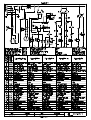
SCHEMI ELETTRICI...................................11-1
CAPITOLO 13..............................................13-1
USO DELLA MACCHINA................................ 3-4 VERIFICHE PRELIMINARI ................................... 3-4 ACCENSIONE MACCHINA ................................... 3-4 USO DEL FERRO DA STIRO (SOLO PER
MACCHINE CON SEPARATORE DI CONDENSA)3-4 USO DELLE FORME PER BRACCIO (riscaldate e
non riscaldate) ........................................................... 3-4 USO DELLA PISTOLA SMACCHIANTE ARIAVAPORE .................................................................. 3-4 USO DEL TAVOLO ................................................ 3-5 FUNZIONAMENTO DEL CONTROLLO LIVELLO
ELETTRONICO DELLA CALDAIA ...................... 3-5 OPERAZIONI DA COMPIERE AL TERMINE
DEL LAVORO .................................................... 3-5 DISEGNI PEZZI DI RICAMBIO.................13-1
CAPITOLO 14..............................................14-1
DISTINTE CODICI........................................14-1
EN
i:\gestione istruzione\_tavoli aspiranti\classic+gemini\aggiornamenti\_4classic+gemini_en.doc (marzo 00)
I N D E X
CHAPTER 1...................................................1-1
SAFETY PRECAUTIONS..............................1-1
CHAPTER 2...................................................2-1
MACHINE IDENTIFICATION.....................2-1
CHAPITER 4 ......................................................4-1 INSTALLATION ................................................ 4-1 PACKING................................................................. 4-1 TRANSPORT ........................................................... 4-1 UNPACKING AND LAYING OF THE MACHINE 4-1 HOW TO ASSEMBLE THE HEIGHT
ADJUSTMENT FEET TO THE TABLE ................. 4-1 LAMP CONNECTION (IF FITTED) ....................... 4-1 HOW TO ASSEMBLE THE BOILER ..................... 4-1 HOW TO ASSEMBLE THE SILICON PLATE FOR
IRON ........................................................................ 4-2 HOW TO ASSEMBLE THE PEDAL GROUP ........ 4-2 HOW TO FIT THE TABLE COVER ....................... 4-2 HOW TO ASSEMBLE THE GARMENT TRAY
AND THE GARMENT TRAY COVER CLOTH .... 4-2 HOW TO ASSEMBLE THE ARM SHAPE ............. 4-2 WATER CONNECTION ......................................... 4-2 COMPRESSED AIR CONNECTION (ONLY FOR
MACHINE WITH SPOTTING GUN) ..................... 4-3 ELECTRICAL CONNECTION ............................... 4-3 BOILER WASHING ................................................ 4-3 MAINTENANCE ................................................ 4-5 WEEKLY MAINTENANCE ................................... 4-5 SIX MONTHLY / YEARLY MAINTENANCE ...... 4-5 BREAKDOWNS .................................................. 4-6 IMMEDIATELY FOLLOWING INSTALLATION 4-6 BREAKDOWNS ON THE BOILER AND ON THE
ELECTRONIC LEVEL CONTROL ........................ 4-6 BOILER HEATING ELEMENT BURNT OUT ...... 4-8 STEAM IRON .......................................................... 4-8 BREAKDOWNS TO THE STEAM/AIR SPOTTING
GUN (IF FITTED) .................................................... 4-8 EXHAUST FAN BREAKDOWNS .......................... 4-8 ORDERING SPARE PARTS ............................. 4-9 STORAGE OR DEMOLITION ......................... 4-9
CHAPTER 10...............................................10-1
TECHNICAL SPECIFICATIONS,
ENCUMBRANCE, CONNECTIONS...........10-1
CHAPTER 11-..............................................11-1
ELECTRICAL DIAGRAMS.........................11-1
CHAPTER 13...............................................13-1
USE OF THE MACHINE .................................. 4-3 PRELIMINARY CONTROLS ................................. 4-3 START-UP OF THE MACHINE ............................. 4-4 USING THE STEAM IRON (FOR MACHINES
WITH CONDENSATE SEPARATOR) ................... 4-4 USING THE HEATED ARM FORMS .................... 4-4 USING THE AIR/STEAM SPOTTING GUN.......... 4-4 USING THE TABLE................................................ 4-4 OPERATION OF THE ELECTRONIC LEVEL
CONTROL ............................................................... 4-4 SHUTTING DOWN OF THE MACHINE ....... 4-5 DRAWING OF SPARE PARTS....................13-1
CHAPTER 14...............................................14-1
CODE’S LIST...............................................14-1
FR
i:\gestione istruzione\_tavoli aspiranti\classic+gemini\aggiornamenti\_5classic+gemini_fr.doc (marzo 00)
T A B L E D E S
M A T I E R E S
CHAPITRE 1..................................................1-1
CONSEILS POUR LA SECURITE DES
PERSONNES ET DES CHOSES....................1-1
OPERATIONS A EFFECTUER A LA FIN DU
TRAVAIL............................................................. 5-5 ENTRETIEN........................................................ 5-5 CHAPITRE 2..................................................2-1
IDENTIFICATION DE LA MACHINE….....2-1
CHAPITRE 5. .....................................................5-1
INSTALLATION ................................................ 5-1 EMBALLAGE .......................................................... 5-1 TRANSPORT ........................................................... 5-1 DEBALLAGE ET MISE EN PLACE DE LA
MACHINE ................................................................ 5-1 MONTAGE PIEDS DE REGLAGE HAUTER
TABLE ..................................................................... 5-1 MONTAGE LAMPE (OU PRESENT)..................... 5-1 ASSEMBLAGE CHAUDIÈRE ................................ 5-1 MONTAGE PETIT TAPIS SUR LE REPOSE-FER 5-2 MONTAGE GROUPE PEDALES ........................... 5-2 MONTAGE HOUSSE SUR LE PLATEAU............. 5-2 MONTAGE PORTE-VÊTEMENT ET TOILE
PORTE-VÊTEMENT ............................................... 5-2 MONTAGE FORME POUR BRAS ......................... 5-2 BRANCHEMENT EAU ........................................... 5-2 BRANCHEMENT AIR COMPRIME (SEULEMENT
POUR MACHINES AVEC PISTOLETS
DETACHANTS) ...................................................... 5-3 BRANCHEMENT ELECTRIQUE ........................... 5-3 LAVAGE CHAUDIÈRE .......................................... 5-3 USAGE DE LA MACHINE ............................... 5-3 VERIFICATIONS PRELIMINAIRES ..................... 5-3 DEMARRAGE MACHINE ...................................... 5-4 USAGE FER A REPASSER (POUR MACHINES
AVEC SEPARATEUR DE CONDENSAT) ............ 5-4 USAGE FORMES POUR BRAS (chauffées et non
chauffées).................................................................. 5-4 USAGE PISTOLET DETACHANT AIR-VAPEUR 5-4 USAGE DE LA TABLE ........................................... 5-4 FONCTIONNEMENT DU CONTROLE NIVEAU
ELECTRONIQUE DE LA CHAUDIERE ................ 5-5 ENTRETIEN PAR SEMAINE ................................. 5-6 ENTRETIEN SEMESTRIEL/ANNUEL .................. 5-6 PANNES ............................................................... 5-6 PANNES IMMEDIATEMENT APRES
L’INSTALLATION, POUR MACHINES AVEC
CHAUDIERE ........................................................... 5-6 PANNES A LA CHAUDIERE ET AU CONTROLE
NIVEAU ELECTRONIQUE .................................... 5-7 BRULURE DE LA RESISTANCE CHAUDIERE .. 5-8 PANNES AU FER .................................................... 5-8 PANNES AU PISTOLET DETACHANT AIR /
VAPEUR (OU PRESENT) ....................................... 5-9 PANNES A L’ASPIRATEUR .................................. 5-9 COMMANDE DES PIECES DE RECHANGE 5-9 STOCKAGE OU DEMOLITION .................... 5-10 CHAPITRE 10............................................ 10-1
DONNEES TECHNIQUES, COTES DE
ENCOMBREMENT, BRANCHEMENTS...10-1
CHAPITRE 11..............................................11-1
SCHEMAS ELECTRIQUES........................11-1
CHAPITRE 13..............................................13-1
DESSINS PIECES DE RECHANGE...........13-1
CHAPITRE 14..............................................14-1
LISTES DES CODES.............................…...14-1
DE
i:\gestione istruzione\_tavoli aspiranti\classic+gemini\aggiornamenti\_6classic+gemini_de.doc (marzo 00)
I N H A L T
KAPITEL 1.....................................................1-1
SICHERHEITSHINWEISE FÜR PERSONEN
UND GEGENSTÄNDE....................................1-1
DURCHZUFÜHRENDE ARBEITE NACH
BEENDIGUNG DES GEBRAUCHS ................. 6-6 WARTUNG .......................................................... 6-6 KAPITEL 2.....................................................2-1
IDENTIFIZIERUNG DER MASCHINE .......2-1
KAPITEL 6. ........................................................6-1 INSTALLATION ................................................ 6-1 VERPACKUNG ....................................................... 6-1 TRANSPORT ........................................................... 6-1 AUSPACKEN UND AUFSTELLEN DER
MASCHINE ............................................................. 6-1 MONTAGE DER STANDBEINE MIT
HÖHENREGULIERUNG ........................................ 6-1 MONTAGE DER BELEUCHTUNGSVORRICHTUNG (SOFERN VORHANDEN) ......... 6-1 ZUSAMMENBAU DES KESSELS ......................... 6-2 MONTAGE ANLEITUNG DER SILIKONBÜGELEISENABLAGE .......................................... 6-2 MONTAGE DER PEDALSTEUERUNG ................ 6-2 MONTAGEANLEITUNG FÜR DEN TISCHBEZUG6-2 MONTAGE DER KLEIDERTHALTER SOWIE DER
TEXTILEN ABDECKUNG ..................................... 6-2 MONTAGE DER ARMFORMEN ........................... 6-2 WASSERANSCHLUSS ........................................... 6-3 DRUCKLUFTANSCHLUSS (NUR FÜR
UNTERDAMPBÜGELTISCHE UND/ODER
DETACHIERPISTOLEN) ........................................ 6-3 ELEKTRISCHER ANSCHLUSS ............................. 6-3 REINIGUNG DES KESSELS .................................. 6-4 GEBRAUCH DER MASCHINE ....................... 6-4 VORPRÜFUNGEN .................................................. 6-4 INBETRIEBNAHME ............................................... 6-4 GEBRAUCH DES BÜGELEISENS (FÜR
MASCHINEN MIT KONDENSATABSCHEIDER) 6-5 GEBRAUCH DER BÜGELFORM (beheizt und
unbeheizt) ................................................................. 6-5 GEBRAUCH DER DAMPF/LUFT
DETACHIERPISTOLE ............................................ 6-5 GEBRAUCH DES TISCHES ................................... 6-5 BETRIEB DER ELEKTRONISCHEN
NIVEAUKONTROLLE DES KESSELS ................. 6-5 WÖCHENTLICHE WARTUNG ............................. 6-7 HALBJÄHRLICHE/JÄHRLICHE WARTUNG ...... 6-7 STÖRUNGEN ...................................................... 6-8 STÖRUNGEN SOFORT NACH DER
INSTALLATION ..................................................... 6-8 STÖRUNGEN AM KESSEL UND AN DER
ELEKTRONISCHEN NIVEAUKONTROLLE ....... 6-8 DURCHGEBRANNTE KESSELWIDERSTÄNDE6-10 STÖRUNGEN AM BÜGELEISEN ....................... 6-10 STÖRUNGEN AN DER DAMPF/LUFT
DETACHIERPISTOLE (SOFERN VORHANDEN)6-10 STÖRUNGEN AN DER ABSAUGUNG ............... 6-11 BESTELLUNG DER ERSATZTEILE............6-11 AUSSERBETRIEBSETZUNG ODER ABBAU6-11 KAPITEL 10................................................ 10-1
TECHNISCHE DATEN, RAUMBEDARF,
ANSCHLÜSSE. ... ..............................................10-1
KAPITEL 11..................................................11-1
ELEKTRISCHES SCHALTPLAN...............11-1
KAPITEL 13..................................................13-1
TEILSCHNITTZEICHNUNGEN DER
ERSATZTEILEN..........................................13-1
KAPITEL 14..................................................14-1
VERZEICHNIS DER CODES......................14-1
ES
i:\gestione istruzione\_tavoli aspiranti\classic+gemini\aggiornamenti\_7classic+gemini_es.doc (marzo 00)
Í N D I C E
CAPÍTULO 1..................................................1-1
ADVERTENCIAS PARA LA SEGURIDAD DE
LAS PERSONAS Y DE LAS COSAS…….....1-1
OPERACIONES A REALIZAR AL FINAL
DEL TRABAJO ................................................... 7-5 MANTENIMIENTO ........................................... 7-5 CAPÍTULO 2..................................................2-1
IDENTIFICACIÓN DE LA MÁQUINA.......2-1
CAPÍTULO 7 ......................................................7-1
INSTALACIÓN .................................................. 7-1 EMBALAJE ............................................................. 7-1 TRANSPORTE ......................................................... 7-1 DESEMBALAJE Y UBICACIÓN DE LA MÁQUINA7-1 REGULACIÓN DE LA ALTURA DE LA MESA .. 7-1 MONTAJE DE LA LUZ .......................................... 7-1 MONTAJE CALDERA ............................................ 7-1 MONTAJE DE LA ALFOMBRA SOBRE EL
APOYO DE LA PLANCHA .................................... 7-2 MONTAJE DE LOS PEDALES ............................... 7-2 MONTAJE PARA VESTIDURA MESA ................. 7-2 MONTAJE DEL SOPORTE PARA PRENDAS Y DE
LA TELA DE SOPORTE PARA PRENDAS .......... 7-2 MONTAJE DE LA FORMA PARA EL BRAZO .... 7-2 CONEXIÓN DEL AGUA ........................................ 7-2 CONEXIÓN DEL AIRE COMPRIMIDO (SOLO
PARA MÁQUINAS CON PISTOLAS
DESMANCHADORAS) .......................................... 7-3 CONEXIÓN ELÉCTRICA ....................................... 7-3 LAVADO DE LA CALDERA ................................. 7-3 EMPLEO DE LA MÁQUINA ........................... 7-4 VERIFICACIONES PRELIMINARES .................... 7-4 PUESTA EN MARCHA DE LA MÁQUINA .......... 7-4 EMPLEO DE LA PLANCHA (PARA MÁQUINAS
CON SEPARADOR DE CONDENSADOS) ........... 7-4 EMPLEO DE LAS FORMAS PARA EL BRAZO
(calentadas y no calentadas) ..................................... 7-4 EMPLEO DE LA PISTOLA DESMANCHADORA
AIRE-VAPOR .......................................................... 7-4 EMPLEO DE LA MESA .......................................... 7-5 FUNCIONAMIENTO DEL CONTROL DEL NIVEL
ELECTRÓNICO DE LA CALDERA ...................... 7-5 MANTENIMIENTO SEMANAL ............................ 7-6 MANTENIMIENTO SEMESTRAL/ANUAL ......... 7-6 AVERÍAS ............................................................. 7-7 AVERÍAS INMEDIATAMENTE DESPUÉS DE LA
INSTALACIÓN ....................................................... 7-7 AVERÍAS EN LA CALDERA Y EN EL CONTROL
ELECTRÓNICO DEL NIVEL ................................. 7-7 QUEMADURA DE LA RESISTENCIA DE LA
CALDERA ............................................................... 7-8 AVERÍAS EN LA PLANCHA ................................. 7-9 AVERÍAS EN LA PISTOLA DESMANCHADORA
AIRE / VAPOR (SI SE ENCUENTRA PRESENTE)7-9 AVERÍAS EN EL ASPIRADOR ............................. 7-9 MODALIDAD PARA EL PEDIDO DE
REPUESTOS ..................................................... 7-10 ALMACENAJE O DEMOLICIÓN ................. 7-10 CAPÍTULO 10.............................................. 10-1
DATOS TÉCNICOS, TAMAÑO,
CONEXIONES..............................................10-1
CAPÍTULO 11...............................................11-1
ESQUEMAS ELÉCTRICOS......................11-1
CAPÍTULO 13...............................................13-1
DIBUJOS DE LOS REPUESTOS.................13-1
CAPÍTULO 14..............................................14-1
LISTAS DE LOS CÓDIGOS........................14-1
CAPITOLO 1 – CHAPTER 1 - CHAPITRE 1 – KAPITEL 1 – CAPÍTULO 1
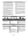
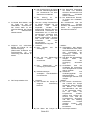
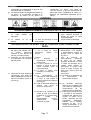
SEGNALI DI PRESCRIZIONE, PERICOLO E INDICAZIONE
PRESCRIPTION, DANGER AND INDICATION SIGNALS
SIGNAUX DE PRESCRIPTION, DANGER ET INDICATION
VERBOTS-, GEBOTS- UND WARNZEICHEN
SEÑALES DE PRESCRIPCIÓN, PELIGRO Y INDICACIÓN
Divieto di togliere i carter di protezione con impianto funzionante
Do not remove protection covers when machine is working.
Défense d’enlever les couvercles de protection pendant le fonctionnement de la machine.
Abnahme der Schutzgehäuse bei anlaufender Anlage verboten
Prohibido quitar la tapa de protección durante el funcionamiento de la maquina.
Divieto di eseguire interventi di manutenzione a macchina in moto
Do not effect maintenance when machine is working.
Défense d’exécuter toutes entretiens pendant le fonctionnement de la machine.
Wartungseinsätze bei anlaufender Anlage verboten
Prohibido efectuar todos mantenimientos durante el funcionamiento de la maquina.
Vietata l’apertura del quadro elettrico al personale non autorizzato.
Authorized personnel only can open the electric panel.
Défense d’ouvrir le cadre électrique par le personnel non autorisé.
Öffnung des Gehäuses für Unbefugte verboten.
Prohibido abrir el tablero eléctrico para obreros no autorizados
Vietato utilizzare acqua per spegnere l’incendio.
Do not extinguish with water
Défense d’eteindre avec de l’eau.
Mit Wasser löschen verboten
Prohibido apagar con agua
Obbligo di riposizionare i carter di protezione prima di azionare l’impianto
Protection covers must be put on before using the machine.
Il est obligatoire de remettre le couvercle de protection avant d’actionner la machine.
Vor Inbetriebsetzung der Anlage Schutzgehäuse wiedereinbauen
Está obligatorio reponer las tapas de protección antes que se ponga en marcha la maquina.
Consultare il manuale d’uso, lo schema elettrico e le procedure.
Consult the instruction’s manual, the electric diagram and procedures.
Consulter le manuel d’emploi.
Betriebsanweisung, Schaltschema und Vorgänge lesen
Consultar el manual d’empleo.
Attenzione pericolo di scottature alle mani
High temperatures! Possibility of burning!
Hautes températures! Danger de brûlures!
Warnung vor Handverbrennungen
Temperaturas elevadas! Peligro de quemaduras!
Quadro in tensione
Danger: electricity
Danger électrique
Warnung vor gefährlicher elektrischer Spannung 380 V
Peligro: Tensión eléctrica
Pag. 1-1
CAPITOLO 1 – CHAPTER 1 - CHAPITRE 1 – KAPITEL 1 – CAPÍTULO 1
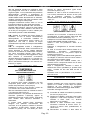
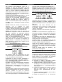
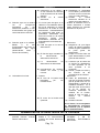
INFORMAZIONI PER LO SMALTIMENTO
DELL’APPARECCHIATURA
L’etichetta con il contenitore di
spazzatura mobile barrato presente
sul prodotto, indica che il prodotto non
deve essere smaltito tramite la
convenzionale
procedura
di
smaltimento dei rifiuti domestici.
Per evitare eventuali danni per l’ambiente e per la
salute umana, il prodotto deve essere separato dagli
altri rifiuti domestici e consegnato al punto di raccolta
designato per il riciclo dei rifiuti elettrici o elettronici.
recueil désigné pour le recyclage des rebuts électriques
et électroniques.
Le recueil diversifié et le recyclage des pièces de rebut
servent pour la conservation des résources naturelles
et à préserver l’habitat et le salut des gens.
L’écoulement abusif du produit sera poursuivi aux
termes de la loi.
Pour tout autre renseignement concernent les points de
recueils disponibles, s’adresser à l’organisme
compétent local ou au revendeur du produit,
INFORMATION ÜBER ENTSORGUNG VON
ALTGERÄTEN
La raccolta differenziata ed il riciclo degli apparecchi di
scarto servirà a conservare le risorse naturali ed a
salvaguardare l’ambiente e la salute delle persone. Lo
smaltimento abusivo del prodotto sarà perseguito a
norma di legge.
Per maggiori dettagli sui centri di raccolta disponibili
contattare l’ente locale competente o il rivenditore del
prodotto.
INFORMATION FOR THE DISPOSAL OF THE
EQUIPMENT
The label showing the crossed mobile
garbage container on the product,
points out that the product must not be
disposed through the conventional
procedure of disposal of the domestic
waste.
To avoid possible damage to the environment and for
improved human health, the product has to be
separated from the other domestic waste and delivered
to the designated collection point for the recycling of
electric or electronic waste.
The diversified collection and the recycling of rejected
instruments will serve to preserve the natural resources
and to safeguard the environment and the health of the
people. The unauthorized disposal of the product will be
prohibited according to the local laws.
Das auf dem Produkt befindliche
Etikett, das eine durchgestrichene
Abfalltonne auf Rädern darstellt,
weist auf das Verbot hin, dieses
Produkt als Hausabfall zu entsorgen.
Um
eventuelle
Umwelt–
und
Gesundheitsschäden zu vermeiden, muß das Produkt
von anderen Hausabfällen getrennt werden und zur
Entsorgung an zuständige Recyclingfirmen bzw.
Sammelorte für Elektro- und Elektronik-Altgeräte
übergeben werden.
Die getrennte Sammlung und Recycling der Altgeräte
dient zur Bewahrung des natürlichen Reichtums und
zum Schutz von Umwelt und Gesundheit.
Eine nicht umweltgerechte Beseitigung des Produkts
wird gesetzlich bestraft.
Für weitere Information betreffend der verfügbaren
Sammelorte, wenden sich an die örtliche zuständigen
Behörden oder an Ihren Produkthändler.
INFORMACIONES POR LA LIQUIDACIÓN DE LA
INSTRUMENTACIÓN
La etiqueta con el contenedor de
basura móvil barrato presente sobre
el producto, indica que el producto no
tiene que ser eliminado por el
convencional
procedimiento
de
liquidación
de
los
rechazos
domésticos.
For greater details on the available collection centres
please contact the competent local authority or the
retailer of the product.
RENSEIGNEMENTS POUR L’ECOULEMENT DE LA
MACHINE
Para evitar eventuales daños por el entorno y por la
salud humana, el producto tiene que ser separado por
los demás rechazos domésticos y remitidos al punto de
colección designado por el reciclo rechazos eléctricos o
electrónicos.
L’Etiquette avec la poubelle barrée
qu’il y a sur le produit, signifie que le
produit même ne peut pas être écoulé
par
le
canal
conventionnel
d’écoulement
des
ordures
domestiques.
La colección distinta y el reciclo aparatos de descarte
servirá a conservar los recursos naturales y a
salvaguardar el entorno y la salud de las personas. La
liquidación abusiva del producto será perseguida a
norma de ley.
Pour éviter d’éventuels dommages pour l’habitat et le
salut de l’homme, la machine doit être séparée des
autres ordures domestiques et livrée jusqu’au point de
Para mayores detalles sobre los centros de colección
disponible contactar al ente local competente o el
detallista del producto.
Pag. 1-2
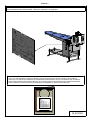
Capitolo 2
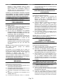
IDENTIFICAZIONE DELLA MACCHINA - IDENTIFICATION OF THE MACHINE - IDENTIFICATION DE LA MACHINE
IDENTIFIZIERUNG DER MASCHINEN - IDENTIFICATIÓN DE LA MAQUINA
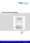
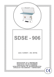
COPIA TARGHETTA DATI TECNICI E' RIPORTATA SULLA COPERTINA DI QUESTO MANUALE
COPY OF THE TECHNICAL SPECIFICATIONS PLATE IS REPRODUCED ON THE COVER OF THIS MANUAL
COPIE DE LA PLAQUE DES DONNEES TECHNIQUES EST REPRODUITE SUR LA COVERTURE DE CE MANUEL
KOPIE DES TECNHISCHEN-DATEN ETIKETTE IST AUF DEN UMSCHLAG DIESER ANLEITUNG REPRODUZIERT
COPIA TARJETA DATOS TECNICOS ES REPRODUCIDA SOBRE EL FORRO DE ESTO MANUAL
M_00763/2
Pag.2-1
ITALIANO
CAPITOLO 3
ITALIANO
Capitolo 3 .
d) Al termine dell'installazione rimontare con
cura i pannelli e le protezioni della macchina.
INSTALLAZIONE
IMBALLO
La macchina viene imballata mediante uno
scatolone di cartone sigillato con nastro adesivo e
reggia.
TRASPORTO
Subito al ricevimento della macchina imballata,
notificare per scritto al trasportatore eventuali
danni subiti dall’imballo durante il trasporto.
Infatti, qualora tali danni abbiano interessato
anche la macchina, l’assicurazione del corriere
risponderà solo se tali danni presunti sono stati
subito segnalati.
Tutte le operazioni di installazione devono essere
eseguite da personale qualificato, munito delle
necessarie
protezioni
(guanti,
protezioni
antinfortunistiche etc.). Non usare getti d’acqua
contro la macchina per nessun motivo ed evitare
bruschi movimenti o urti violenti.
La macchina non deve essere trasportata da
braccia umane, bensì con l'ausilio di muletti o
paranchi meccanici.
Trasportare la macchina completa di imballo nel
luogo più prossimo al punto di installazione e
procedere al suo disimballaggio.
Devono essere osservate alcune misure di
distanza dalle pareti e dalle altre macchine, al fine
di garantire una lavorazione più scorrevole ed una
perfetta manutenzione.
La macchina non necessita di alcun ancoraggio al
pavimento.
Si raccomanda di sistemarla perfettamente in
piano.
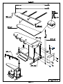
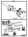
MONTAGGIO PIEDINI DI
REGOLAZIONE ALTEZZA
TAVOLO
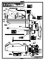
(VEDI DISEGNO A PAG. 10-4 FIG. 1,2)
L’altezza della macchina da terra può essere
variata manualmente, da 750 a 930 mm,
servendosi degli appositi piedini di regolazione.
Procedere nel seguente modo:
a) Montare le quattro barre filettate “POS. 42” ed
i piedini “POS. 43”, come indicato in FIG. 2,
inclinando la macchina sul lato anteriore per
montare
il
piedino
posteriore
e,
successivamente, sul lato posteriore per
montare il piedino anteriore.
b) Bloccare i dadi in modo che la macchina si
trovi all’altezza desiderata.
DISIMBALLAGGIO E POSA
DELLA MACCHINA
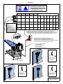
MONTAGGIO DELLA LAMPADA
(VEDI DISEGNO A PAG. 10-2)
(VEDI DISEGNO A PAG. 10-6)
Procedere nel seguente modo:
a) Estrarre dallo scatolone la macchina e gli
accessori, verificando che non abbiano subito
danneggiamenti durante il trasporto.
b) Imbragare la macchina con due funi
(verificare che siano idonee al peso totale
della macchina rilevabile dal cartellino dati
tecnici), l'una nella parte posteriore, l'altra
nella parte anteriore della macchina; quindi,
con l'ausilio di un muletto o paranco
meccanico, sollevare la macchina e
posizionarla
nel
luogo
destinato
all'installazione senza più muoverla con
braccia umane.
c) Procedere al montaggio degli eventuali
accessori in dotazione (vedi paragrafi
seguenti).
Procedere nel seguente modo:
a) Fissare la gamba porta lampada “POS. 31”
alla macchina nei punti previsti “POS. 31a”
senza stringere a fondo i bulloni di fissaggio.
b) Inserire la lampada “POS. 41” nella gamba
porta-lampada e ruotarla fino a far
corrispondere la sua estremità con il centro
della punta del tavolo; tutto ciò al fine di
illuminare correttamente il tavolo da stiro ed
ottimizzare l’uso del ferro da stiro. Procedere,
quindi, a stringere a fondo i bulloni di
fissaggio.
c) Collegare
elettricamente
la
lampada
seguendo lo schema elettrico corrispondente
(vedi capitolo 11).
(SE PRESENTE)
Pag. 3-1
ITALIANO
CAPITOLO 3
f)
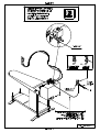
MONTAGGIO DELLA CALDAIA
ITALIANO
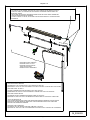
Tirare contemporaneamente le due estremità
delle cordicelle “POS. 40”.
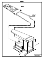
MONTAGGIO REGGI-INDUMENTI
E TELA REGGI-INDUMENTI
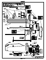
(VEDI DISEGNO A PAG. 10-9)
Procedere nel seguente modo:
a) Smontare il poggiaferro.
b) Fissare la caldaia alla macchina avvitandola
mediante le viti e bulloni in dotazione, in
corrispondenza dei quattro fori previsti sul
telaio.
c) Rimontare il poggiaferro.
MONTAGGIO TAPPETINO SUL
POGGIAFERRO
(VEDI DISEGNO A PAG. 10-5 FIG. 3)
(VEDI DISEGNO A PAG. 10-7)
Procedere nel seguente modo:
a) Montare il reggi-indumenti “POS. 35”
infilandolo nei due fori posti sotto il tavolo da
stiro, far combaciare i fori del reggi-indumenti
con quelli presenti sul telaio e fissarlo
mediante le due viti autofilettanti in dotazione.
b) Calzare la tela elasticizzata “POS. 37” sul
reggi-indumenti “POS. 35”.
Appoggiare il tappetino di silicone “POS. 33“ sul
poggiaferro “POS. 32“.
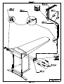
MONTAGGIO FORMA PER
BRACCIO
MONTAGGIO PEDALIERA
(VEDI DISEGNO A PAG. 10-8)
(VEDI DISEGNO A PAG. 10-5 FIG.4)
Procedere nel modo seguente:
a) Fissare la pedaliera al telaio della macchina
avvitandola mediante le due viti in dotazione,
in corrispondenza dei fori posti sul basamento
della macchina.
Le due serie di forature permettono il fissaggio
della pedaliera alla distanza desiderata dal tavolo.
MONTAGGIO TELA DI
COPERTURA TAVOLO
(VEDI DISEGNO A PAG. 10-6)
a) Appoggiare sul tavolo la rete con feltro “POS.
35”, facendo aderire la rete al tavolo.
b) Inserire i due tondini A e B nella tela “POS.
36”.
c) Calzare la tela “POS. 36”, controllando che
aderisca perfettamente al tavolo.
d) Agganciare un’estremità delle molle al tondino
A, avendo cura di non agganciare le cordicelle
“POS. 40”.
e) Facendo passare le molle sotto il tavolo,
agganciare la seconda estremità al tondino B,
avendo cura di non agganciare le cordicelle
“POS. 40”.
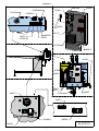
Procedere nel seguente modo:
a) Fissare la flangia della forma braccio “POS.
51” sul lato del tavolo desiderato, servendosi
dei 4 bulloni in dotazione “POS. 48”.
b) Lubrificare gli snodi filettati. Se con l’uso il
braccio acquistasse eccessivo gioco, è
possibile annullare tale gioco avvitando il
braccio in senso orario (filetti conici).
c) Montare il braccio “POS. 53” avvitandolo in
senso orario nella flangia “POS. 51”.
d) Montare la forma “POS. 54” avvitandola in
senso orario nel braccio “POS. 53”. Nel caso
di forma riscaldata:
Fissare la presa “POS. 56” sulla parte
posteriore del telaio della macchina ed
eseguire il collegamento elettrico (vedi
schema elettrico).
Inserire la spina della forma riscaldata
“POS. 55” nella presa “POS. 56” ed
agganciarle.
Fissare il cavo elettrico al braccio “POS.
53” mediante le due molle “POS. 61”.
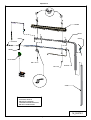
COLLEGAMENTO ACQUA
(VEDI DISEGNO A PAG. 10-11)
Predisporre un tubo in ferro zincato da 3/8”GAS
fino a cm 100 dalla macchina.
Pag. 3-2
ITALIANO
CAPITOLO 3
ITALIANO
Alla sua estremità montare un rubinetto a sfera
con portagomma “POS. 66” e, mediante un tubo
di gomma (Øint. 13 mm) resistente alla pressione
dell’acquedotto, collegare il portagomma di
entrata acqua “POS. 14” al rubinetto. Qualora la
caldaia debba essere alimentata da un serbatoio,
chiedere informazioni alla Ditta produttrice sulle
modifiche da eseguire sulla pompa.
Collegare il rubinetto di scarico “POS. 17” con la
fognatura mediante un tubo rigido termoisolato.
Qualora non fosse disponibile nelle vicinanze un
pozzetto della fognatura, oppure se fosse vietato
scaricarvi acqua calda, utilizzare una tanica da
15-20 litri per raccogliere lo scarico caldaia (che
scaricherete quando si sarà raffreddata).
pericolo di natura pneumatica (getti d’aria,
movimenti di pistoni, etc.).
Mediante un tubo in rilsan di interno=6mm (
0,23 inches) resistente ad almeno 20 bar (290
psi) di pressione, collegare il rubinetto
all’elettrovalvola aria della pistola smacchiante
“POS. 47”.
N.B.: Qualora le normative del Vostro Paese lo
richiedano, al fine di evitare contaminazioni
dell’acquedotto, è necessario installare un
serbatoio di alimentazione acqua oppure un
apparecchio che eviti il riflusso di acqua
eventualmente inquinata (ad esempio GIACOMINI
R 624).
N.B.: È consigliabile evitare il collegamento
all’addolcitore dell’acqua. Infatti, l’eventuale uso di
acqua depurata in piccole caldaie elettriche
provoca la formazione di abbondante schiuma,
che viene risucchiata quando viene usato il
vapore, con conseguente danneggiamento degli
abiti. Qualora si riscontrasse un’eccessiva
durezza dell’acqua (maggiore di 17° francesi=12°
inglesi), è possibile installare un addolcitore che
riduca i sali disciolti nell’acqua a non meno di 10
francesi (7 inglesi).
Accertarsi che la tensione e frequenza di linea
corrispondano a quelle segnate sulla targa dati
tecnici della macchina (vedere pag. 2-1).
Predisporre una linea elettrica dimensionata come
indicato dalla tabella riportata nel disegno.
Inserire il cavo nel pressacavo “POS. 8” e
bloccarlo.
Effettuare il collegamento ai morsetti d’entrata
corrente.
La linea di corrente dovrà essere dotata di un
interruttore
automatico
magnetotermico
differenziale da 30 mA, con presa e spina ad
interblocco meccanico.
Si fa obbligo, pena la decadenza della garanzia,
di collegare la macchina ad una buona messa a
terra secondo le normative vigenti.
Controllare, prima del collaudo iniziale, che i
morsetti di tutti i componenti elettrici non si siano
allentati durante il trasporto.
Dopo il collegamento, verificare il senso di
rotazione dei motori (ventilatori) e, qualora fosse
errato, invertire tra loro due delle tre fasi in
ingresso.
Rimontare tutte le pannellature e le protezioni
della macchina.
COLLEGAMENTO ARIA
COMPRESSA
(SOLO PER MACCHINE CON
PISTOLE SMACCHIANTI)
COLLEGAMENTO ELETTRICO
(VEDI DISEGNO A PAG. 10-10)
LAVAGGIO CALDAIA
(VEDI DISEGNO A PAG. 10-11)
La macchina deve essere alimentata con aria
compressa pulita, senza condense né oli, ed
avente una pressione di 7 bar (100 psi).
Predisporre un tubo in ferro zincato o rilsan da
1/4” GAS fino ad 1 metro dalla macchina.
Alla sua estremità montare un rubinetto a sfera a
3 vie oppure a slitta “POS. 25”.
Questo rubinetto a 3 vie permette di alimentare la
macchina (posizione 1=ON=OK) oppure di
disattivarla (posizione 0=OFF=STOP), scaricando
l’aria rimasta nella macchina attraverso il
silenziatore.
In questo modo, qualora fosse necessario
eseguire una qualsiasi manutenzione alla
macchina, si ha la garanzia, ruotando il rubinetto
in posizione 0=OFF=STOP (oppure facendo
scivolare la ghiera), che non esista più alcun
Quando s’installa una nuova macchina, oppure
quando la si rimette in moto dopo una pausa
superiore ad una settimana, è necessario
effettuare un abbondante lavaggio della caldaia.
Procedere nel seguente modo:
a) Accendere la caldaia e mandarla in pressione
fino a 2 bar (30 psi) circa.
b) Spegnere la caldaia e scaricare l’acqua nella
fognatura o nella tanica aprendo a metà il
rubinetto a sfera “POS. 17”, facendo
attenzione a non scottarsi.
c) Quando è stata scaricata tutta l’acqua,
richiudere il rubinetto di scarico “POS. 17”.
L’acqua di scarico sarà, probabilmente, di
colore scuro.
d) Riaccendere la caldaia e farla salire di
Pag. 3-3
ITALIANO
CAPITOLO 3
pressione fino a 2 bar (30 psi).
e) Ripetere i punti b), c), d) ciclicamente per 4
volte. Nel frattempo l’acqua scaricata sarà
diventata pulita. Se, al contrario, l’acqua
contiene ancora dello sporco, ripetere il
“lavaggio” ancora 3 - 4 volte, finché l’acqua
scaricata sarà perfettamente pulita.
Qualora non si procedesse ad effettuare il
lavaggio caldaia, si rischia d’avere risucchi
d’acqua scura o di colore ruggine durante le
fasi di vaporizzazione.
USO DELLA MACCHINA
VERIFICHE PRELIMINARI
Procedere come segue (vedi dis. a pag. 10-11):
a) Controllare che il rubinetto a sfera di scarico
della caldaia “POS.17” sia ben chiuso.
b) Controllare che il rubinetto a sfera
d’alimentazione dell’acqua “POS. 66” sia
aperto.
c) Nel caso di macchina con pistole
smacchianti aria-vapore, controllare che il
rubinetto a sfera d’alimentazione aria
compressa “POS. 25” sia aperto.
d) Se la macchina è rimasta ferma per molto
tempo, accertarsi che la pompa non si sia
bloccata a causa delle incrostazioni interne.
Controllare quindi che l’albero giri a mano; a
tale scopo utilizzare l’intaglio per cacciavite
sull’estremità dell’albero, lato ventilatore.
N.B.: Non fare funzionare la pompa con il
rubinetto
dell’acqua
chiuso,
perché
si
danneggerebbe irreparabilmente.
Inizialmente, con la macchina fredda, il vapore in
arrivo si condenserà rapidamente; è, quindi,
consigliabile attendere qualche minuto prima di
iniziare la lavorazione, affinché tutta la condensa
formata si possa scaricare.
Non attenendoVi a questa norma, l’abbondante
condensa che si forma uscirebbe dalle tubazioni
di vaporizzazione, danneggiando il capo.
ITALIANO
USO DEL FERRO DA STIRO
(SOLO PER MACCHINE CON SEPARATORE DI
CONDENSA)
(VEDI DISEGNO A PAG. 13-1)
Procedere nel seguente modo:
a) Alcuni minuti prima di iniziare la stiratura
accendere l’interruttore ferro da stiro “POS.
98” ed accertarsi che il volantino del
termostato si trovi all’incirca all’inizio del
quadrante medio.
b) Impugnare il ferro e premere ad intervalli il
pulsante fino a quando uscirà il vapore.
Osservare bene che il vapore uscente dal
ferro non sia misto ad acqua; qualora ciò si
verificasse, vuol dire che la temperatura del
ferro è troppo bassa, per cui occorrerà
attendere qualche minuto prima di iniziare la
lavorazione.
c) Se necessario, regolare la quantità del flusso
di
vapore
agendo
sul
volantino
dell’elettrovalvola vapore.
N.B.: Per l’uso del “Ferro da stiro elettronico” fare
riferimento al manuale specifico.
USO DELLE FORME PER
BRACCIO
(riscaldate e non riscaldate)
(VEDI DISEGNI A PAG. 13-1)
Procedere nel seguente modo:
a) Ruotare la forma per braccio che si desidera
utilizzare, portandola in posizione di lavoro.
b) Accendere l’interruttore generale “POS. 69”:
attivando in tal modo il dispositivo di riscaldamento, la cui temperatura è controllata da
un termostato posto all’interno della forma.
c) Per favorire l’utilizzo dell’aspiratore alla forma
per braccio, ruotare la leva “POS. 48” in senso
antiorario fino ad escludere completa-mente
l’aspirazione dal tavolo ed orientarla,
conseguentemente alla forma per braccio.
USO DELLA PISTOLA
SMACCHIANTE ARIA-VAPORE
ACCENSIONE MACCHINA
(VEDI DISEGNO A PAG. 13-1)
(VEDI DISEGNI A PAG. 13-1)
Procedere nel seguente modo:
a) Accendere l’interruttore generale previsto
sulla linea elettrica d’alimentazione
b) Accendere l’interruttore generale della
macchina “POS. 69”.
c) Inserire l’interruttore d’accensione caldaia
“POS. 57”.
d) Attraverso il manometro “POS. 71” controllare
che la pressione del vapore in caldaia
raggiunga il valore di 2,5 bar.
Procedere come segue:
a) Sistemare la parte smacchiante sulla punta
della forma per braccio e premere il pedale di
aspirazione “POS. 86”.
b) Premere il pulsante sinistro della pistola
“POS. 36” per ottenere la fuoriuscita del
vapore. Per i primi secondi il vapore sarà
misto ad acqua; è quindi necessario scaricare
la pistola per qualche secondo, finché non si
sarà ben riscaldata.
Pag. 3-4
ITALIANO
CAPITOLO 3
ITALIANO
c) Dirigere il getto di vapore sul tessuto a cui è
stato applicato il prodotto smacchiante,
muovendo la pistola in senso rotatorio.
Un’abbondante
vaporizzazione
dissolve
istantaneamente le macchie solubili in
acqua.
d) Per asciugare la zona smacchiata, premere
l’eventuale pulsante destro della pistola,
ottenendo la fuoriuscita di aria compressa.
Muovere rapidamente la pistola avanti e
indietro in un movimento a zig-zag, in modo
che l’umidità venga espulsa con l’aria. La forte
aspirazione concentrata favorisce un rapido
asciugamento.
Raggiunto il corretto livello d’acqua in caldaia,
vengono inserite le resistenze.
Ogni volta che la sonda livello viene scoperta, si
riattiva il caricamento acqua, senza disattivare le
resistenze, le quali, si sganciano automaticamente
solo se, trascorsi 20 sec., non si ristabilisce il
livello corretto d’acqua.
Se, passati 2 minuti l’acqua in caldaia non ha
ancora raggiunto il livello, la centralina manderà in
blocco il sistema di caricamento acqua
salvaguardandolo.
USO DEL TAVOLO
(VEDI DISEGNI A PAGG. 13-1 E 10-11)
(VEDI DISEGNO A PAG. 13-1)
a) Alcuni minuti prima del termine del lavoro,
disinserire l’interruttore della caldaia “POS.
57” e continuare la lavorazione fino a quando
si esaurisce il vapore.
b) Quando la pressione in caldaia è scesa a 1
bar (15 psi circa), aprire il rubinetto a sfera di
scarico “POS. 17” e scaricare la caldaia,
quindi richiudere il rubinetto a sfera.
Riaccendere la caldaia facendo entrare nuova
acqua. Appena la pompa si è fermata,
spegnere la caldaia senza scaricare.
c) Chiudere il rubinetto a sfera montato sulla rete
di alimentazione dell’acqua “POS. 66”.
d) Nel caso di macchina con pistole
smacchianti, chiudere il rubinetto a sfera
montato sulla rete di alimentazione aria
compressa “POS. 25”.
e) Disinserire l’interruttore “POS. 69”, quindi
l’interruttore generale previsto sulla linea di
alimentazione.
La temperatura di riscaldamento del tavolo è
controllata da un termostato “POS. 83”; il valore
massimo impostabile è di 90°C= 190°F.
N.B.: Il piano riscaldato può danneggiare gli abiti
se questi vi rimangono appoggiati per lungo
tempo. Pertanto non lasciare mai indumenti sul
piano oltre il tempo necessario per la stiratura.
Per ottenere l’aspirazione dal tavolo, procedere
nel seguente modo:
a) Premere il pedale “POS. 86” per ottenere
l’aspirazione al tavolo. L’aspirazione è
necessaria per fissare le pieghe del
pantalone e per stirare indumenti di tessuto
duro (cotone, ecc.) o particolarmente
stropicciati.
b) Nel caso di macchina con forma per
braccio, ruotare la leva “POS. 48” in senso
orario e gradualmente, al fine di ottenere il
grado di aspirazione desiderato.
FUNZIONAMENTO DEL
CONTROLLO LIVELLO
ELETTRONICO DELLA CALDAIA
Se la caldaia è vuota, la centralina elettronica,
dopo 3” dal suo inserimento, attiva il caricamento
dell’acqua fino a coprire la sonda livello.
Le resistenze della caldaia rimangono disattivate
fino alla prima copertura.
Se, passati 2 minuti dal primo caricamento,
l’acqua in caldaia non ha ancora raggiunto il
livello corretto di lavoro bisognerà verificare che
non sia rimasto chiuso il rubinetto d’ingresso
acqua, nel qual caso occorre aprirlo.
Se, invece, l’acqua arriva regolarmente alla
macchina, occorre verificare il motivo per cui non
è entrata acqua in caldaia.
Per inconvenienti o anomalie di funzionamento
rimandiamo alla lettura del capitolo “Guasti alla
caldaia ed al controllo livello elettronico”.
OPERAZIONI DA COMPIERE
AL TERMINE DEL LAVORO
N.B.: Vi consigliamo di eseguire le operazioni
indicate al punto 1b tutte le sere, se volete avere
una caldaia che si mantenga a lungo ed in buono
stato e che vi eviti fastidiosi risucchi d’acqua.
MANUTENZIONE
Quanto segue è di vitale importanza per avere
una macchina sempre in perfetta efficienza, che vi
darà sempre il massimo rendimento, evitandovi
dispendiosi fermi-macchina.
La prima parte di questa rubrica è divisa in capitoli
a seconda della maggiore o minore frequenza
delle singole manutenzioni.
N.B.: La frequenza da noi indicata (settimanale,
mensile, etc.) è indicativa e si riferisce ad una
macchina che lavori in condizioni “normali”.
Sarete poi Voi stessi a stabilire l’esatta cadenza
delle operazioni di manutenzione, in funzione dei
Pag. 3-5
ITALIANO
CAPITOLO 3
seguenti parametri:
quantità di lavoro eseguito dalla macchina;
durezza dell’acqua, che causa maggiori o
minori depositi di calcare sugli elementi
riscaldanti della caldaia;
pulviscolo nell’aria;
altre particolari condizioni.
Tutte le operazioni di manutenzione vanno
eseguite a macchina completamente spenta ed in
particolare:
a) L’interruttore generale previsto sulla linea
elettrica deve essere spento e la spina deve
essere tolta dalla presa.
b) Il rubinetto a sfera di alimentazione
dell’acqua “POS. 66” deve essere chiuso. Lo
scarico caldaia “POS. 17” deve essere
chiuso.
c) Per le macchine con pistole smacchianti,
deve essere chiuso il rubinetto di
alimentazione aria compressa “POS.25“, che
automaticamente scaricherà l’aria rimasta
nella macchina.
d) Bisogna lasciare raffreddare le parti calde
della macchina (tubi interni, valvole, caldaia,
etc.) al fine di non ustionarsi.
Solo seguendo tutte queste precauzioni ed altre
dettate da particolari condizioni contingenti, è
possibile eseguire le manutenzioni sulla macchina
in assoluta sicurezza, ricordandosi che “la
prudenza non è mai troppa”.
Per rendere più evidenti i pericoli, abbiamo posto
nei punti critici della macchina, dei simboli adesivi
il cui significato viene spiegato dettagliatamente
nella pagina rossa all'inizio di questo manuale
(“Segnali di prescrizione, pericolo e indicazione”).
N.B.: in ogni caso, le manutenzioni devono
essere effettuate solo ed esclusivamente da
personale competente, il quale risponde in
prima persona dell'incolumità propria e d’altre
persone/animali/cose
eventualmente
interessate. La legge, e specialmente le ultime
direttive CEE, puniscono severamente il
proprietario della macchina qualora faccia
eseguire manutenzioni a personale non
competente.
MANUTENZIONE SETTIMANALE
Procedere come segue:
a) Valvola di sicurezza caldaia: verificare il
corretto funzionamento, controllare che non
sfiati vapore. In caso di malfunzionamento,
occorre sostituire l’intera valvola, operazione
per la quale è richiesto l’intervento del tecnico
competente.
b) Verificare il corretto funzionamento di
manometro, pressostato e pompa.
ITALIANO
MANUTENZIONE
SEMESTRALE/ANNUALE
Procedere come segue:
a) Pulire accuratamente le resistenze dai
depositi calcarei che le incrostano. Questa
operazione, di vitale importanza per il
rendimento della caldaia, è di facile
attuazione; basta, infatti, togliere la flangia con
gli elementi riscaldanti e pulirli accuratamente.
È importante, durante tale operazione,
smontare il tubetto che collega la pompa con
la caldaia e pulire il raccordo entrata acqua in
caldaia da eventuali depositi che lo
ostruiscono.
b) Controllare le varie giunzioni e rubinetti a
sfera in quanto, in seguito al continuo
riscaldamento e raffreddamento, si possono
verificare delle perdite. In questo caso si
consiglia di smontare le giunzioni, i rubinetti a
sfera e ripristinare la tenuta.
c) Pulire la reticella del filtro acqua montato
sull’elettrovalvola di alimentazione. Per tale
operazione, smontare il portagomma, togliere
il filtro che si trova all’interno dell’elettrovalvola
e provvedere alla pulizia di quest’ultimo,
mediante un soffio di aria compressa.
d) Smontare i tubetti di rame che collegano il
pressostato ed il manometro e pulirli
internamente da eventuali tamponi di calcare.
e) Smontare la sonda livello e procedere ad
un’accurata pulizia dal calcare che ricopre il
corpo sonda, utilizzando della tela smeriglio.
Assicurarsi, inoltre, che lo stelo/elettrodo non
ruoti nel corpo porta-sonda; diversamente,
stringere il dado superiore.
f) Controllare lo stato di conservazione di tutte le
targhette della macchina (di pericolo o di
istruzione). Qualora fossero deteriorate, è
indispensabile procedere alla loro sostituzione.
g) Eseguire una ispezione visiva all’interno della
caldaia almeno una volta all’anno per
controllare le condizioni delle pareti interne e
la presenza di eventuali incrostazioni e/o
corrosioni. Pulire accuratamente l’interno del
tubo che contiene la sonda.
h) Smontare la valvola di sicurezza e ripulire da
eventuali tamponi di calcare il raccordo sul
quale è montata. Verificare che la valvola
stessa non sia otturata.
i) Pulire il condotto ventilazione aria da eventuali
ostruzioni (lanetta, sporcizie) che ostacolano il
flusso di aria durante la fase di aspirazione.
j) Controllare lo stato di usura dell’imbottitura
del piano e, se necessario, procedere alla sua
sostituzione. L’imbottitura del piano è
considerata, infatti, una parte di normale
consumo, poiché le operazioni di stiratura
tendono ad infeltrirla ed a diminuire la
capacità aspirante del piano.
Pag. 3-6
ITALIANO
CAPITOLO 3
ITALIANO
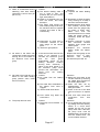
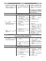
GUASTI
Inconvenienti:
Cause:
Rimedi:
GUASTI SUBITO DOPO L’INSTALLAZIONE
1. La pompa funziona e produce 1. Non arriva acqua alla macchina. 1. Controllare perché non arriva
uno strano rumore senza
l’acqua. Lasciando funzionare
fermarsi.
la pompa senz’acqua, la si
danneggia irreparabilmente.
2. La caldaia non va in 2. Il rubinetto a sfera dello scarico 2. Chiudere il rubinetto a sfera.
pressione.
non è ben chiuso.
GUASTI ALLA CALDAIA ED AL CONTROLLO LIVELLO ELETTRONICO
1. Il rubinetto di alimentazione 1. Non entra acqua in caldaia e, 1. Verificare che l’acqua arrivi
acqua è aperto, ma la
quindi, la centralina elettronica
effettivamente alla macchina
centralina elettronica continua
segnala il guasto.
ed, eventualmente, pulire i
ad andare in allarme (il led
passaggi come indicato al
rosso ed il cicalino pulsano).
punto 5.
2. Risucchio d’acqua durante la 2. Cause:
2. Con la macchina in funzione,
vaporizzazione all’inizio della
scaricare l’acqua dalla caldaia
a) La macchina è rimasta
stiratura.
aprendo lentamente il rubinetto
inutilizzata per parecchie ore.
a sfera di scarico caldaia, fino
b) La sera precedente non si è
a quando non interverrà la
provveduto a chiudere il
pompa per ricaricare acqua. A
rubinetto a sfera montato
questo punto richiudere il
sulla tubazione acqua.
rubinetto di scarico.
c) Il rubinetto a sfera è guasto e
non chiude bene.
3. Risucchio di acqua durante la 3. Cause:
3. Rimedi:
vaporizzazione, anche dopo
a) Elettrovalvola d’alimentazione
a) Procedere alla sostituzione
aver ripristinato il livello
difettosa o sporca, che
dell’elettrovalvola
di
dell’acqua in caldaia (come
impedisce allo spillo di
alimentazione acqua.
punto 2).
chiudere bene, lasciando
entrare acqua.
b) Mancato scarico giornaliero
b) Occorre scaricare ogni sera
della caldaia, che causa la
la caldaia affinché possa
formazione di schiuma.
essere
continuamente
ripulita da schiume e
depositi.
c) Presenza di calcare sulla
c) Smontare la sonda livello e
sonda di livello della caldaia
procedere ad un’accurata
(soprattutto
nella
parte
pulizia dal calcare che
terminale), che ne impedisce
ricopre il corpo sonda,
il corretto funzionamento,
utilizzando
della
tela
determinando continui carichi
smeriglio.
Assicurarsi,
d’acqua.
inoltre, che lo stelo/elettrodo
non ruoti nel corpo portasonda;
diversamente,
stringere il dado superiore.
d) Interruzione sui fili e sui
d) Ripristinare la continuità su
contatti di collegamento della
fili e contatti di collegamento
sonda livello al quadro
tra sonda livello e quadro
elettrico.
elettrico.
e) Guasto
alla
centralina
e) Sostituire
la
centralina
elettronica.
elettronica posta all’interno
del quadro elettrico.
Pag. 3-7
ITALIANO
CAPITOLO 3
ITALIANO
4. Mancanza
di
acqua
in 4. Se il giusto livello di acqua in 4. Sostituire la Sonda livello o la
caldaia con conseguente
caldaia non viene ristabilito
centralina elettronica oppure
bruciatura delle resistenze,
entro 20 sec., la centralina
entrambe. Eseguire i controlli
dovuta
ad
un
cattivo
elettronica o la sonda livello
indicati al punto 3c.
funzionamento del gruppo
staccano automaticamente le
controllo livello elettronico.
resistenze per evitare la loro
bruciatura.
Ovviamente,
un
guasto alla sonda oppure alla
centralina
elettronica
impedirebbe
questo
automatismo, causando, così, la
bruciatura delle resistenze.
5. Mancanza
di
acqua
in 5. Cause:
5. Rimedi:
caldaia, dovuta ad un cattivo
a) Mancanza di acqua dalla rete
a) Accertarsi che arrivi acqua
funzionamento del gruppo
di alimentazione.
alla macchina togliendo il
alimentazione
acqua
tubo di gomma montato sul
(elettrovalvola,
tubetti
e
porta
gomma
di
raccordi di collegamento).
alimentazione.
b) Il
filtro
acqua
montato
b) Pulire la rete del filtro acqua
sull’elettrovalvola
di
smontando il porta gomma
alimentazione è sporco.
di alimentazione.
c) Elettrovalvola
di
c) Controllare che la bobina
alimentazione difettosa.
della valvola di alimentazione non sia bruciata, in tal
caso procedere alla sua
sostituzione.
d) Incrostazioni
di
calcare
d) Liberare e pulire tubetti e
otturano tubetti e raccordi.
raccordi dalle incrostazioni
di calcare.
6. La pompa non funziona.
6. Cause:
6. Rimedi:
a) La girante della pompa è
a) Tentare di sbloccare la
bloccata da incrostazioni.
girante della pompa facendo
ruotare l’albero motore con
un
cacciavite,
tramite
l’intaglio esistente sul lato
motore della pompa: Se non
si
riuscisse,
occorre
smontare il coperchio della
pompa, pulire la girante in
ottone e verificare la corretta
rotazione.
b) Motore pompa bruciato.
b) Sostituire la pompa.
Per il futuro, Vi consigliamo una
più frequente manutenzione
preventiva
(vedi
capitolo
manutenzioni).
BRUCIATURA DELLA RESISTENZA CALDAIA
1. La
resistenza
bruciata 1. Mancanza di acqua in caldaia 1. Vedi
“GUASTI
ALLA
presenta vistose fusioni sul
dovuta
ad
un
irregolare
CALDAIA
ED
AL
tubo esterno.
funzionamento del controllo di
CONTROLLO
LIVELLO
livello elettronico.
ELETTRONICO”.
Pag. 3-8
ITALIANO
CAPITOLO 3
ITALIANO
2. La resistenza bruciata si 2. L’elemento della resistenza è 2. Procedere alla pulizia della
presenta di colore biancastro
avvolto
da
una
spessa
caldaia scrostando bene tutte
con bollicine di fusione lungo
incrostazione di calcare che
le pareti interne prima di
tutta la superficie degli
impedisce la propagazione del
montare la nuova resistenza.
elementi riscaldanti.
calore.
Per il futuro, Vi consigliamo una
più frequente manutenzione
preventiva
(vedi
capitolo
manutenzioni).
GUASTI AL FERRO
1. Il ferro da stiro non scalda.
1. Cause:
1. Rimedi:
a) Interruzione
della
continuità
a) Ripristinare la continuità del
elettrica del cavo.
cavo.
b) Resistenza ferro bruciata.
b) Sostituire
la
resistenza
bruciata.
c) Contatti
termostato
ferro
c) Sostituire il termostato ed il
rovinati e termofusibile saltato.
termofusibile.
scalda 2. Contatti termostato difettosi.
2. Sostituire il termostato.
2. Il ferro da stiro
eccessivamente.
3. Fuoriuscita dal ferro di acqua 3. Cause:
3. Rimedi:
mista a vapore.
a) Temperatura del ferro troppo
a) Ruotare leggermente, in
bassa.
senso orario, il volantino del
termostato
del
ferro,
aumentando,
così,
la
temperatura del ferro.
b) Risucchio di acqua dalla
b) Vedi paragrafo “Guasti alla
caldaia stessa.
caldaia”.
4. Fuoriuscita
di
vapore 4. Temperatura del ferro troppo 4. Ruotare leggermente, in senso
surriscaldato dal ferro.
elevata.
antiorario, il volantino del
termostato
del
ferro,
diminuendo,
così,
la
temperatura del ferro.
GUASTI ALLA PISTOLA SMACCHIANTE ARIA / VAPORE (SE
ESISTENTE)
1. Il vapore arriva regolarmente 1. Cause:
alla
macchina
tuttavia,
a) Contatto
premendo il pulsante della
difettoso.
pistola, non esce dall’ugello
1. Rimedi:
a) Controllare la funzionalità
del contatto microinterruttore
ed eventualmente sostituirlo.
b) Ripristinare la continuità
b) Interruzione
continuità
elettrica del cavo pistola.
elettrica cavo pistola.
c) Sostituire bobina bruciata.
c) Bobina elettrovalvola bruciata.
microinterruttore
GUASTI ALL’ASPIRATORE
1. L’aspiratore non funziona.
1. Cause:
1. Rimedi:
a) La ventola è bloccata da corpi
a) Sbloccare la ventola,
estranei.
rimuovendola dai corpi
estranei che la bloccano.
b) Il microinterruttore del pedale
b) Sostituire il micronon funziona.
interruttore del pedale.
c) Il condensatore del motore è
c) Sostituire il condensatore
bruciato.
del motore.
d) Il motore è bruciato.
d) Sostituire il motore.
Pag. 3-9
ITALIANO
CAPITOLO 3
RICHIESTA DEI PEZZI DI
RICAMBIO
ITALIANO
ACCANTONAMENTO O
DEMOLIZIONE
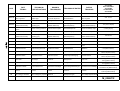
I ricambi devono essere ordinati esclusivamente
tramite fax, fornendo codici e descrizioni, al fine di
poter garantire l’invio dei pezzi in tempi brevi.
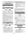
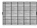
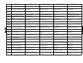
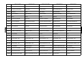
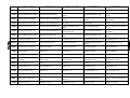
IMPORTANTE:
Per i componenti elettrici con tensione e
frequenza diverse da 220V/230V/240V 50Hz.
(dati da confrontare con quelli della targhetta
dell'articolo guasto) far seguire al codice di
ordinazione la lettera corrispondente alla tensione
desiderata, come da seguente tabella:
A
B
C
D
E
F
G
H
I
L
M
220V/230V 60Hz.
240V 50Hz.
200V 50Hz.
200V 60Hz.
190V 50Hz.
115V 60Hz.
110V 60Hz.
208V 50Hz.
24V 50Hz.
240V 60Hz.
254V 50Hz.
In caso d’accantonamento per lungo periodo,
occorre scollegare le fonti d’alimentazione
idrauliche, elettriche, pneumatiche.
Procedere come segue:
a) Scaricare la caldaia, l’eventuale serbatoio
d’alimentazione dell'acqua e l’eventuale
serbatoio separatore condense.
b) Al fine di evitare la rottura della pompa per il
gelo, scaricare l'acqua rimasta all'interno del
corpo pompa. Allentare la vite a testa
esagonale, avvitata sulla parte inferiore del
corpo pompa, quindi rimontarla.
c) Provvedere alla pulizia delle pareti interne
della caldaia da depositi melmosi e dalle
incrostazioni di calcare.
d) Pulire i raccordi della caldaia ed i vari tubetti
da eventuali tamponi di calcare.
e) Al termine di queste operazioni richiudere tutti
i rubinetti a sfera d’alimentazione e scarico
acqua
Rimontare tutte le pannellature di chiusura della
macchina e rivestirla con un telo per proteggerla
dall'umidità e dalla polvere.
Esempio 1:
Occorre una bobina teleruttore a 230V/50 Hz.
Dati completi per l’ordine:
Macchina Modello: Caldaia Tipo...
Matricola N° 110227
Codice 04775-bobina teleruttore 230V/50 Hz
N° 1 pezzo
In caso di demolizione agire nel seguente modo:
a) Scaricare direttamente nella fognatura l’acqua
rimasta in caldaia, nell'eventuale serbatoio
recupero condense, nell'eventuale serbatoio
alimentazione acqua, assicurandosi che siano
privi d’impurità nocive.
b) Rimuovere tutta la componentistica, elettrica,
idraulica e pneumatica, dai pannelli su cui è
fissata.
c) Raccogliere plastica, bachelite, ghisa, ferro,
rame, ottone, acciaio, stoffe, gomma etc. negli
appositi contenitori e smaltirli secondo le
norme vigenti.
Esempio 2:
Stessa bobina, ma a 254V/50Hz.
Dati completi per l’ordine:
Macchina Modello: Caldaia Tipo…
Matricola N° 110228
Codice 04775/M-bobina teleruttore
254V/50Hz
N° 1 pezzo
N.B.:
1. I particolari che compaiono su questo
manuale senza il numero di codice a fianco,
NON SONO DISPONIBILI a magazzino.
2. La sigla “POS. 66” oppure “POS. 17” etc. che
compare a fianco di alcuni particolari, non ha
nulla a che vedere con il codice di quel
particolare e quindi non deve essere citata
nell’ordinazione dei ricambi.
I DATI, LE DESCRIZIONI E LE ILLUSTRAZIONI
CONTENUTI NEL PRESENTE OPUSCOLO NON
SONO IN ALCUN MODO IMPEGNATIVI. LA
FABBRICA SI RISERVA IL DIRITTO DI
APPORTARE, IN QUALSIASI MOMENTO, TUTTI
I CAMBIAMENTI CHE RITERRÀ OPPORTUNI,
SENZA L’OBBLIGO DI AGGIORNARE IL
PRESENTE OPUSCOLO.
Sperando che queste pagine possano
esserVi utili come ci siamo ripromessi,
non ci rimane che augurarVi BUON
LAVORO!
L’UFFICIO TECNICO
Pag.3-10
ENGLISH
CHAPTER 4
ENGLISH
Capitolo 4 dfdgdhh
The equipment does not require any fixing to the
floor. It is recommended that the equipment
should be installed dead level
INSTALLATION
PACKING
The machine is packed in a box closed with an
adhesive band.
TRANSPORT
HOW TO ASSEMBLE THE
HEIGHT ADJUSTMENT FEET TO
THE TABLE
(SEE DRAWING PAGE 10-4 FIG.1,2)
Upon receipt of the machine packed, you are
kindly requested to immediately report to the
forwarding agent any damage suffered by the
packing during the transport.
In case of damages to the machine as well, the
insurance company of the forwarding agent will be
held responsible only if these damages have been
reported immediately.
Only competent personnel equipped with the
necessary protection must undertake all the
installation operations.
Do not use water jets against the machine for any
reason and avoid sudden movement or violent
blows.
Do not carry the machine by hand, but only by
forklift truck or tackle. It is advisable to move the
machine complete with the packing to where it is
to be installed and then unpack the machine.
UNPACKING AND LAYING OF
THE MACHINE
(SEE DRAWING PAGE 10-2)
Proceed as following:
a) Remove the box and verify that the machine
has not suffered damages during the
transport.
b) Sling the machine by means of two roper
(verify that are suitable for the total weight of
the machine), one at the rear and the other at
the front side of machine; then lift it by means
of forklift truck or tackle and place it where it
must be installed, without moving it by hand.
c) Connect accessories, if present (see next
paragraphs).
d) When installation has been completed,
carefully refit all the panels, protection devices
and the accessories.
Various distances from the walls and other
equipment must be observed during the
installation of the machine in order to ensure
smooth operation and good maintenance.
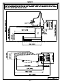
The unit height can be altered manually, from
750mm to 930mm, by the relevant small feet in
the following way:
a) Fit the four threaded bars “POS. 42” and the
feet “POS. 43”, as shown in FIG. 2. By lifting
the unit on the right you can fit the left foot
and on the left, you can fit the right foot.
b) Lock the nuts so that unit is adjusted to the
required height.
LAMP CONNECTION
(IF FITTED)
(SEE DRAWING PAGE 10-6)
Proceed as follows:
a) Fix the lamp holder rod “POS. 31” to the
machine at the prepared points “POS. 31a”
without completely tightening the bolts.
b) Insert the lamp “POS. 41” in the lamp holder
rod and turn it until its end meets the centre
of the end of the board; this is so that the
ironing board is correctly illuminated and to
optimize the use of the iron. At this point you
can tighten the bolts.
c) Connect the lamp electrically following the
corresponding electrical outline (see chapter
11).
HOW TO ASSEMBLE THE
BOILER
(VEDI DISEGNO A PAG. 10-9)
Proceed as follows:
a) Disassemble the iron rest.
b) Assemble the boiler on the machine by fixing
it trough the screws and bolts supplied, at the
four holes on the frame.
c) Reassemble the iron rest.
Page 4-1
ENGLISH
CHAPTER 4
ENGLISH
HOW TO ASSEMBLE
THE SILICON PLATE FOR IRON
inserting it into the two holes placed under
the finishing board, match the holes between
the garment tray and the machine frame,
then fix it using the two self-threading screws
supplied.
b) Put on the elasticised cloth “POS. 37” on the
garment tray “POS.35”.
(SEE DRAWING PAGE 10-5 FIG. 3)
HOW TO ASSEMBLE THE ARM
SHAPE
Position the silicon part “POS. 33” on the iron rest
“POS. 32”.
HOW TO ASSEMBLE THE
PEDAL GROUP
(SEE DRAWING PAGE 10-8)
(SEE DRAWING PAGE 10-5 FIG.4)
Proceed in the following way:
a) Assemble the pedal group to the unit frame
fitting the two screws available, in the
corresponding holes located on the frame
itself.
The two sets adjustment holes are to fix the
pedals to the wished distance from the table.
HOW TO FIT THE TABLE COVER
(SEE DRAWING PAGE 10-6)
a) Put the mesh followed by the felt “POS. 35”,
making it flush to the buck.
b) Thread the 2 rods A and B into the cloth cover
“POS. 36”.
c) Put on the cloth cover “POS. 36” checking
that it is perfectly flush to the board.
d) Hook one edge of the springs to the rod A,
checking that the cords “POS. 40” are not
caught.
e) Hook the second edge of the rod B by running
the springs under the buck and checking that
the cords “POS. 40” are not caught.
f) Pull at the same time the two ends of the
cords “POS. 40”.
HOW TO ASSEMBLE THE
GARMENT TRAY AND THE
GARMENT TRAY COVER CLOTH
(SEE DRAWING PAGE 10-7)
Proceed as follows:
a) Assemble the garment tray “POS. 35”
Proceed as follows:
a) Fix the flange of the arm shape “POS. 51” at
the side of the board by means of the 4 issued
bolts “POS. 48”.
b) Lubricate the threaded joints: if using the arm
it would have an excessive slack, screw the
arm clockwise (conical threads).
c) Assemble the arm “POS. 53” screwing it
clockwise into the flange “POS. 51”.
d) Assemble the shape “POS. 54” screwing it
clockwise in the arm “POS. 53”. In case of
heated shape:
Connect the socket “POS. 56” on the rear
side of the frame of the machine and
carry out the electric connection (see
electric circuit).
Put the plug of the heated form “POS. 55”
in the socket “POS. 56” and hook them.
Fix the electric cable to the arm “POS. 53”
by means of the two springs “POS. 61”.
WATER CONNECTION
(SEE DRAWING PAGE 10-11)
Fit a 3/8" zinc-platted gas pipe to within 100 cm
of the machine.
Fit a ball valve with tube connector “POS. 66” to
the end of the tube, and connect it by a rubber
hose (Øint 13 mm) suited to the mains water
pressure to the water input ”POS. 14”.
In the case of the boiler being feed from a water
tank, request the manufacture for information
regarding the modifications to be made to the
pump. Connect the drainage gate valve “POS. 17”
to the drain using a rigid heat-insulated pipe.
In the case of there not being a drain near by, or
the drainage of hot water not being allowed, use a
15-20 litre tank to collect the boiler waste water
(the water can then be disposed of when it has
cooled).
Page 4-2
ENGLISH
CHAPTER 4
ENGLISH
N.B.: If local regulations regarding the
contamination of the water mains so require,
install a water feed tank or one-way flow device to
prevent the back-flow of possibly polluted water to
the water mains (for example, a GIACOMINI R
624).
N.B.: It is advisable to avoid connecting a water
softener as the use of treated water in small
electrical boilers causes the formation of copious
quantities of foam which is drawn in to the
machine when steam is used, with consequent
damage to the clothes.
In the case of excessively hard water (more than
17° French=12° English), a water softener may be
installed to reduce the dissolved salts by no more
than 10° (French) or 7° (English).
The electrical supply line must be fitted with an
automatic differential heat safety cut-out switch 30
mA with a mechanical plug and socket block.
The machine as per the rules in force must be
connected to a good earth, or the guarantee will
not be honoured.
Before first testing the machine, check that none
of the electrical connectors have worked loose
during transport.
After connection to the electricity supply, check
the rotation direction of the motors (fan).
If the direction is wrong, invert the connection of
two of the three phases supply wires.
Replace all the panels and protection devices
when the electrical connections have been
completed.
COMPRESSED AIR
CONNECTION
BOILER WASHING
(SEE DRAWING PAGE 10-11)
(ONLY FOR MACHINE WITH SPOTTING GUN)
The machine needs to be fed with clean
compressed air, without condensation or oil, at a
pressure of 7 bars (100 psi).
Fit a rilsan or zinc-platted 1/4" gas pipe to within 1
meter of the machine. Assemble a three-way ball
tap or a sliding tap on its end “POS. 25”.
This 3-way ball valve serves to feed the machine
(position 1 = ON = OK) or to turn off the supply
(position 0 = STOP) by discharging the air
remaining in the machine through the silencer.
This ensures that whenever any maintenance is
required, there is the guarantee that there is no
danger from compressed air (jets of air, etc.)
simply by turning the air ball valve to the 0 =
STOP position (or letting the ring nut slip).
Using a pipe in rilsan, inside=6mm (0,23
inches) resistant up to a pressure of at least 20
bars (290 psi), connect the tap to the air solenoid
valve of the spotting gun “POS. 47”.
ELECTRICAL CONNECTION
When a new machine is installed, or when
restarting after it has been stopped for more than
one week, the boiler must be thoroughly
washed.
The procedure is as follows:
a) Turn on the boiler and bring it to a pressure of
approximately 2 bars (30 psi).
b) Turn the boiler off and drain the water into the
main drains or drainage tank half opening the
tap “POS. 17”, taking care not to burn
yourself.
c) When all the water has been drained, turn off
the drainage valve “POS. 17”. The water will
probably be a dark colour.
d) Turn the boiler on again and bring it to a
pressure of 2 bars (30 psi).
e) Repeat the cycle of points b) - c) - d) four
times.
The water should progressively become
cleaner. If it is still dirty, repeat the washing
cycle another 3 or 4 times, until it is
completely clean.
If the boiler is not washed as described above
there is the risk of dirty water being siphoned
back, or a rust colour visible during steaming.
USE OF THE MACHINE
PRELIMINARY CONTROLS
(SEE DRAWING PAGE 10-10)
Ensure that the mains voltage and phase
correspond with the data given on the machine
specification plate (see page 2-1).
Prepare an electrical line dimensioned as
indicated on the table shown in the drawing.
Insert the cable in the holder “POS. 8” and block
it. Connect with the clamps to the electrical
current.
Proceed as follows (see drawing page 10-11):
a) Check that the drainage ball valve “POS. 17”
is well closed
b) Check that the water feed ball “POS. 66” is
open
c) In case of machine with steam-air spotting
gun, check that the ball tap for the
compressed air feed “POS. 25” is open.
d) If the machine has been stopped for a long
time check that the pump is not jammed due
to internal deposit. Check that the shaft turns
Page 4-3
ENGLISH
CHAPTER 4
manually using the carving for screwdriver on
the shaft end, ventilation
N.B.: Do not run the pump with the water valve
closed as this will ruin irreparably the pump.
At first, when the machine is cold, the steam will
condense rapidly and it is therefore advisable to
wait a few minutes before starting work so that the
condensation can be drained off.
If this is not done, condensation formed will
emerge from the steam pipes, damaging the
garments being processed.
START-UP OF THE MACHINE
(SEE DRAWING PAGE 13-1)
Proceed as follows:
a) Turn on the general electrical supply switch
b) Turn on the main switch of the machine “POS.
69”.
c) Turn on the boiler switch “POS. 57.
d) Check on the manometer “POS. 71” that the
steam pressure reaches to 2,5 bar.
USING THE STEAM IRON
(FOR MACHINES WITH CONDENSATE
SEPARATOR)
ENGLISH
USING THE AIR/STEAM
SPOTTING GUN
(SEE DRAWING PAGE 13-1)
Proceed in the following way:
a) Place the part of the item to be cleaned on the
end of the support and press vacuum pedal
“POS. 86”.
b) Press the left button of the gun “POS. 36” to
release the steam. For the first few seconds
the steam is mixed with water. Therefore
discharge the gun for a few seconds until it is
well heated.
c) Distribute the jet of steam onto the stain with
the gun. Abundant steaming instantly
dissolves water-soluble stains.
d) If required dry the stained area spray stain
with compressed air by pressing the button on
the right of the gun.
Move the gun rapidly back and forth in a
zigzag motion to remove the dampness in the
stain with the air. The strong, concentrated
vacuum allows rapid drying.
USING THE TABLE
(SEE DRAWING PAGE 13-1)
Proceed as follows:
a) A few minutes before beginning the finishing
operation switch on the iron switch “POS. 98”
and check that the knob of thermostat is about
at the centre of the middle quadrant.
b) Hold the iron and push at regular intervals the
push button until some steam comes out.
Verify that steam coming out from the iron is
not mixed with water, as in this case this
would mean that the temperature of the iron is
too low therefore wait for some minutes.
c) If necessary, control the quantity of steam flux
by means of the knob of steam valve.
N.B.: for use of the ‘Electronic Iron’, see the
specific manual relating to the iron.
USING THE HEATED ARM
FORMS
(SEE DRAWINGS PAGE 13-1)
Proceed in the following way:
a) Rotate the arm form that you want to use by
placing it in the work position.
b) Turn on the heating switch for the arm forms
“POS. 69”. A thermostat on the inside of the
form controls the heating temperature.
c) To help the use of the aspirator on the arm
form, rotate the lever “POS. 48” counterclockwise until the aspirator is completely off
the board and then orient it to the arm form.
(SEE DRAWING PAGE 13-1)
The board heat temperature is controlled by the
thermostat “POS. 83”; the maximum temperature
that can be set is 90°C=190°F.
N.B.: The entire heated surface can damage
clothing if they remain in contact with it for a long
time. Therefore, do not leave clothing on the
ironing surface for prolonged period of time.
To obtain vacuum in the table, proceed in the
following way:
a) Press pedal “POS. 86” to obtain vacuum in
the table. Vacuum is used to fix trouser
creases and to finishing garments made from
heavy materials (cotton etc.) or on garments
that are very creased.
b) In case of machine with arm shape, rotate the
lever “POS. 48” gradually and clockwise to
obtain the necessary vacuum.
OPERATION OF THE
ELECTRONIC LEVEL CONTROL
When the boiler is empty, the electronic timer,
after 3 seconds from switch on, will call for water
till to cover the probe.
The heating elements are switched off till the
water has reached the water level sensor probe. If
after a further 2 minutes the water has not
reached the right level for work, check that the
water supply valve is not closed and if so, open
the valve and reset the machine. If the water
Page 4-4
ENGLISH
CHAPTER 4
supply is correct, first check the reason why water
is not running in the boiler.
For further troubles or anomalies in operation,
please read the chapter "Breakdowns to the boiler
and to electronic level".
In operation when the correct water level is
obtained the heating elements are switched on.
As the water level decreases and the level sensor
probe becomes uncovered, the water pump and
inlet valve are again switched on without switching
off the heating elements that if after this 20
seconds delay the correct water level is not
restored than the heating elements are switched
off automatically.
If after 2 minutes, the water has not reached the
level to work, the timer will block the water loading
device safeguarding it.
SHUTTING DOWN OF THE
MACHINE
(SEE DRAWINGS PAGE 13-1 AND 10-11)
a) A few minutes before stopping work, turn off
the boiler by “POS. 57” and continue working
until the steam is finished.
b) When the boiler pressure has dropped below
approximately 1 bar (approximately 15 psi),
open the discharge gate valve "POS.17",
empty the boiler and then close the gate
valve. Turn the boiler on again, and run in
fresh water. As soon as the pump has
stopped, turn the boiler off without draining it.
c) Turn off the water supply ball valve “POS. 66”.
d) In the case of machine with steam spotting
gun, close the ball tap assembled on the air
compression line “POS. 25”.
e) Disconnect the switch “POS. 69”, then the
main switch on the electrical current line.
N.B.: It is advisable to carry out the procedure in
1b every evening to ensure a long and efficient
boiler life and to avoid the siphoning-back of
water.
MAINTENANCE
ENGLISH
exact frequency of the maintenance work on the
basis of the following guide lines:
the amount of work done by the machine;
the hardness of the water, which causes a
greater or lesser scaling of the boiler heating
element;
the amount of dust in the air;
other local working conditions.
All the maintenance operations must be
undertaken with the machine completely switched
off, and in particular:
a) The general electrical power switch must be
off and the plug removed from the socket;
b) The water supply ball “POS. 66” must be
closed. The boiler drainage valve “POS. 17”
must be closed;
c) In case of machine with spotting gun the
compressed air ball valve “POS. 25” must be
closed and all the compressed air in the
machine must be discharged.
d) The hot parts of the machine must be left to
cool (internal pipes, valves, boiler, etc.) in
order to avoid burns.
Only by observing all these precautions, and the
particular conditions relating to the individual
maintenance jobs, is it possible to carry out
maintenance work on the machine with complete
safety. Remember ‘you can never be too
careful’!
In order to make potential dangers more evident,
adhesive symbols have been applied to critical
parts of the machine: the meaning of these
symbols is explained in detail in the red section at
the beginning of this manual (Prescription, danger
and indication signals).
N.B. In any case, the maintenance work must
be undertaken only by competent personnel
who can take personal responsibility for their
own safety and that of other persons, animals
and property. The law, and in particular the
latest EU Directives, severely punish the
owner of a machine who allows maintenance
work to be carried out by non-qualified
personnel.
WEEKLY MAINTENANCE
The following instructions are of prime importance
in keeping the machine perfectly efficient,
ensuring its maximum performance, and avoiding
expensive down time.
The first part of this section is divided into
chapters according to periodic maintenance
schedules.
N.B.: The frequency indicated (weekly, monthly,
etc.) is indicative and refers to a machine that
operates under ‘normal’ conditions.
The individual customer has to decide on the
Proceed as follows:
a) Boiler safety valves: check carefully its
correct working and that it does not vent
steam. In the case of a malfunction, replace
the whole safety valve: request the services
of a competent technician.
b) Also check the correct functioning of the
gauge, pressure gauge and pump.
SIX MONTHLY / YEARLY
MAINTENANCE
Proceed as follows:
a) Carefully clean the heating elements of any
Page 4-5
ENGLISH
b)
c)
d)
e)
CHAPTER 4
scaling. This is of a great importance for the
performance of the boiler, and it is easy to do.
Simply remove the flange with the heating
elements and carefully clean them. During this
operation it is important to disconnect the tube
that connects the pump to the boiler, and
clean the joint, where the water enters into the
boiler, of any deposits that may be obstructing
it.
Check the various gaskets and gate valves as
continuous heating and cooling can cause
leaks. Should there be leaks, remove the
gaskets and gate valves and replace with new
to prevent further leaks.
Clean the water filter fitted to the feed
electrovalve. To do this, remove the sleeve,
remove the filter inside the electrovalve and
clean the latter with compressed air.
Disconnect the copper pipes that connect the
gauge and the pressure gauge and clean
them internally to remove any scaling.
Remove the probe and carefully clean it of
any sediment or scaling using an emery cloth.
Assuring that the spindle/electrode doesn't
revolve in the sonde support body, otherwise
tighten the superior nut.
ENGLISH
f)
Check the condition of all the labels and
plates on the machine (warnings and
instructions). If they are in poor condition,
replace them.
g) Carry out a visual inspection inside the boiler,
at least once a year, to control the conditions
of the inside walls and the presence of
possible scales and/or corrosions. Carefully
clean the inside of the pipe containing the
probe.
h) Disassemble the safety valve and clean the
joint, on which is assembled, of any scaling.
Also check that the valve is not obstructed.
i) Clean the air pipe from any impediment (dirty)
that stops the airflow during the ventilation
phase.
j) Check the wear of the board padding and, if
necessary, substitute it. The board padding is
considered a part of the normal wear and tear
since ironing tends to matt the padding and
decreases the aspiration and steaming
capacities of the board.
BREAKDOWNS
Problem:
Causes:
Action:
IMMEDIATELY FOLLOWING INSTALLATION
1. The
pump
works
and 1. Water is
produces a strange noise
machine
without stopping
not
reaching
the 1. Check the reason for the water
not reaching the machine.
Letting the pump run without
water will damage it beyond
repair.
2. The boiler does not gain 2. The drainage gate valve is not 2. Close the drainage gate valve
pressure.
tightly closed.
BREAKDOWNS ON THE BOILER AND ON THE ELECTRONIC LEVEL
CONTROL
1. The water feeding valve is 1. Water is not fed into the boiler 1. Check that water is actually
open, but the electronic
and the station is signalling the
fed into the machine and, if
station alarm is on (red led is
error.
necessary,
clean
the
blinking
and
alarm
is
passages as indicated at
beeping).
Pos.5.
2. Water is sucked back during 2. Causes:
2. With the machine in operation,
steam generation at ironing
drain water from the boiler by
a) The machines has not been
start.
opening the boiler drain ball
used for several hours.
valve slowly until the pump
b) The ball valve on the water
starts re-loading water. Now
pipe was not closed on the
close the drain cock.
previous evening.
c) The ball valve is out of order
and does not close properly.
Page 4-6
ENGLISH
CHAPTER 4
ENGLISH
3. Water is sucked back during 3. Causes:
3. Solutions:
steaming, even after having
a) The electric feeding valve is
a) Replace the water feeding
restored the correct level (as
out of order or dirty, and
valve.
per Pos. 2).
prevents the pin from closing
tight, water leaks in.
b) Water is not drained every day
b) Remember to drain the boiler
from the boiler, and foam
every evening so as keep it
develops.
free from foam and scales.
c) The boiler level gauge has
c) Disassemble the level gauge
lime scales (mostly on its end):
and carefully remove lime
the machine does not operate
scales from the gauge body
correctly and water is fed in
by means of emery cloth.
continuously.
Make
sure
that
the
pin/electrode does not rotate
inside the gauge holder, if
necessary screw the upper
nut tight.
d) Interruption on wires and on
d) Restore continuity on wires
connection contacts of the
and connection contacts
level gauge on the electric
between level gauge and
panel.
electric panel.
e) Electronic group failure.
e) Replace
the
electronic
station inside the electric
panel.
4. No water in the boiler with 4. If the correct water level into the 4. Replace the level gauge or the
consequent heating elements
boiler is not restored in 20
electronic group or both.
burning due to the failure of
seconds the electronic group
Performs
the
checking
the electronic level control
and
the
level
gauge
procedure as per POS. 3C.
group.
automatically switch off the
heating
elements,
avoiding
burning them. Obviously a
failure of the level gauge or of
the electronic group would
prevent this automatism and
would
burn
the
heating
elements.
5. No water in the boiler due to a 5. Causes:
5. Solutions:
failure of the water feeding
a) No water from the feeding
a) Make sure that water is fed
group (electric valve, tubes
system.
into the machine by removing
and connections).
the rubber pipe mounted on
the feeding pipe holder.
b) The water filter assembled on
b) Clean the filter net by
the electric feed valve is
disassembling the rubber
clogged.
feed pipe holder.
c) Electric feed valve failure.
c) Check if the coil of the feed
valve is burned, if so replace
it.
d) Lime scales clog tubes and
d) Free and clean tubes and
connections.
connections
from
lime
scales.
6. The pump does not work.
6. Causes:
6. Solutions:
a) The pump rotor is blocked by
a) Try to operate the pump rotor
scales.
by rotating the motor shaft by
means of a screw driver
applied into the slit on the
pump motor side. If this fails,
the pump cover must be
disassembled, the brass fan
must be cleaned and the
correct rotation checked.
Page 4-7
ENGLISH
CHAPTER 4
b) Pump Motor burned.
ENGLISH
b) Replace the pump motor.
More
frequent
preventive
maintenance is recommended
in the future (See Section
“MAINTENANCE”).
BOILER HEATING ELEMENT BURNT OUT
1. The burnt-out element shows 1. Lack of water in the boiler due 1. See “BREAKDOWNS ON
cleat signs of melting of the
to
malfunctioning
of
the
THE BOILER AND ON THE
external copper tube.
electronic level control.
ELECTRONIC
LEVEL
CONTROL”.
2. The burnt-out element is a 2. The heating element is covered 2. Clean the boiler and remove
whitsh colour with blisters all
with thick scaling that inhibits
all scaling before fitting a new
along the heating element
the diffusion of heat
heating element
surfaces
More
frequent
preventive
maintenance is recommended in
the
future
(See
chapter
“MAINTENANCE”).
STEAM IRON
1. Steam iron does not heat.
1. Causes:
a) Break of cable continuity.
1. Solutions:
a) Repair the electric cable
continuity.
b) Iron resistance burned.
b) Replace
the
burned
resistance.
c) Iron
thermostat
contacts
c) Replace the thermostat and
faulty.
the fuse.
2. Steam iron overheating.
2. Thermostat contacts faulty.
2. Replace the thermostat
3. From the iron comes water 3. Causes:
3. Solutions:
mixed with steam.
a) Iron temperature too low.
a) Rotate the iron thermostat
handwheel
clockwise,
increasing
the
iron
temperature.
b) Boiler
suction
due
to
b) See
paragraph
anomalies of the boiler itself.
“BREAKDOWNS TO THE
BOILER”
4. Steam overheated from the 4. Iron temperature too high.
4. Rotate the iron thermostat
iron.
handwheel
anticlockwise,
decreasing
the
iron
temperature.
BREAKDOWNS TO THE STEAM/AIR SPOTTING GUN (IF FITTED)
1. Steam available to the 1. Causes:
1. Solutions:
machine, but pushing the gun
a) Microswitch contact defective.
a) Check
the
microswitch
button no steam available
contact and if necessary
from nozzle.
replace it.
b) Break of the gun cable
b) Check the continuity and
continuity.
repair accordingly.
c) Solenoid valve coil burned.
c) Replace burned coil.
EXHAUST FAN BREAKDOWNS
1. The exhaust fan does not 1. Causes:
work.
a) Foreign objects block the fan.
1. Solutions:
a) Unblock the fan by removing
the foreign bodies that are
blocking it.
b) The micro-switch on the pedal
b) Change the micro-switch on
does not work.
the pedal.
c) The motor condenser is
c) Change
the
motor
burned out.
condenser.
d) The motor is burned out.
d) Change the motor.
Page 4-8
ENGLISH
CHAPTER 4
ORDERING SPARE PARTS
The spare parts must be ordered only by fax with
codes and descriptions in order to ensure the
rapid despatch of the parts.
IMPORTANT
For electrical components other than for
220V/230V/240V 50 Hz supply (check on the
specification plate of the defective part), add to
the order code the letter corresponding to the
rating required as given in the following table:
A
220V/230V 60Hz.
B
240V 50Hz.
C
200V 50Hz.
D
200V 60Hz.
E
190V 50Hz.
F
115V 60Hz.
G
110V 60Hz.
H
208V 50Hz.
I
24V 50Hz.
L
240V 60Hz.
M
254V 50Hz.
Example 1:
A 230V/50 Hz coil remote control switch is
required.
Complete order information:
Machine model: Boiler Type .....
Registration No. 110227
Code No. 04775 - coil remote control switch
230V/50 Hz
1 piece
Example 2:
The same coil, but 254V/50 Hz.
Complete order information:
Machine model: Boiler Type .....
Registration No. 110228
Code No. 04775/M - coil remote control
switch 254V/50 Hz
1 piece
N.B.
1. The parts that appear in this manual without
an accompanying code number ARE NOT
AVAILABLE from stock.
2. The codes “POS. 66” or “POS. 17” etc. that
appear next to some parts have nothing to do
with the spare part code for these parts, and
should not therefore be quoted in orders for
spare parts.
ENGLISH
Proceed as follows:
a) Drain the boiler, the condensates tanks and
also the water feeding tank (if existing).
b) Drain all the water left into the pump, by
unscrewing the hexagonal screw on the lower
side of the pump casing (the side of the water
feeding), then screw again.
c) Carefully clean the internal walls of the boiler
of any sediment or scaling.
d) Clean the boiler connections and pipes to
remove any scaling.
e) When all these operations have been
completed, turn off the water feeding valves
and the drainage valves.
Carefully refit all the panels of the machine and
cover it with a cloth to shelter from the humidity
and dust.
In case of demolition of the machine, proceed as
follows:
a) Drain the boiler, the condensate tank and the
water feeding tank directly into the sewerage
system after having made sure that no
harmful impurities are inside the water.
b) Remove all the electric, pneumatic and
hydraulics components from the panels
where they are fixed.
c) Collect into proper container the following
parts: plastic, bakelite, cast iron, iron, copper,
brass, steel, fabrics, rubber etc. and take
them away according to the rules in force.
THE SPECIFICATIONS, THE DESCRIPTIONS
AND THE ILLUSTRATIONS CONTAINED IN
THIS BOOKLET ARE NOT IN ANY WAY
BINDING. DUE TO CONTINUOUS RESEARCH
AND DEVELOPMENT TO IMPROVE OUR
PRODUCTS, THE MANUFACTURER MAY
ALTER
SPECIFICATIONS
WITHOUT
PREVIOUS NOTICE.
We trust that these few pages will be of
use to you and wish you ‘Buon lavoro!’ as
we say in Italy — May your work go well!
STORAGE OR DEMOLITION
In case of a long period storage, it is necessary
to disconnect the hydraulics, electric and
pneumatic feeding sources.
Page 4-9
Technical Office
FRANCAIS
Capitolo 5
CHAPITRE 5
FRANCAIS
.
La machine ne nécessite d’aucun ancrage au sol.
Nous Vous recommandons de la poser sur une
surface parfaitement plane.
INSTALLATION
EMBALLAGE
MONTAGE PIEDS DE REGLAGE
HAUTER TABLE
La machine est emballée dans un carton fermé
avec ruban adhésif.
TRANSPORT
(VOIR DESSIN A LA PAGE 10-4 FIG. 1,2)
À la livraison de la machine emballée, nous Vous
prions de notifier immédiatement par écrit au
transporteur les dommages éventuels subis par
l’emballage pendant le transport.
Dans le cas où ces dommages ont intéressé la
machine, en effet, l’assurance du courrier
répondra seulement si les dommages présumés
ont été signalés immédiatement.
Toutes opérations d’installation doivent être
exécutées par du personnel qualifié, muni des
protections nécessaires (gants, protections contre
les accidents, etc.). N’utiliser pas de jets d’eau
contre la machine pour aucune raison, et éviter
les mouvements soudains ou les chocs violents.
La machine ne doit être jamais transportée à bras,
mais avec l’aide de chariots élévateurs et palans
mécaniques.
Transporter la machine encore complètement
emballée jusqu’à l’endroit le plus proche au point
d’installation et procéder au déballage.
DEBALLAGE ET MISE EN PLACE DE
LA MACHINE
(VOIR DESSIN A LA PAGE 10-2)
Procéder de la manière suivante:
a) Oter du carton la machine et les accessoires,
et vérifier qu’ils n’ont pas subi dommages
pendant le transport.
b) Elinguer la machine avec deux cordes (vérifier
qu’elles sont appropriées pour le poids total
de la machine, qui peut être relevé de la
plaquette données techniques), l’une du côté
postérieur et l’autre du côté antérieur de la
machine; enfin, à l’aide d’un chariot élévateur
ou d’un palan mécanique, soulever la
machine et la positionner dans l’endroit
destiné à l’installation sans plus la déplacer à
bras.
c) Procéder à monter les éventuels accessoires
(voir chapitres suivants).
d) À
la
fin
de
l'installation,
remonter
soigneusement les panneaux et les
protections de la machine.
L’hauteur de la machine du sol peut être changée
manuellement, de 750 à 930 mm, par les
spéciaux pieds de réglage.
Procéder de la manière suivante:
a) Monter les quatre barres filetées “POS. 42” et
les pieds “POS. 43”, comme indiqué dans la
FIG. 2, inclinant la machine sur le côté
antérieure pour monter le pied postérieure et,
ensuite, sur le côté postérieure pour monter le
pied antérieure.
b) Bloquer les écrous de façon que la machine
se trouve à l’hauteur requise.
MONTAGE LAMPE
(OU PRESENT)
(VOIR DESSIN PAGE 10-6)
Procéder de la manière suivante:
a) Fixer le support de l’éclairage “POS.31” à la
machine aux endroits prévus “POS.31a” sans
serrer complètement les boulons de fixage.
b) Insérer la lampe “POS. 41” dans le pieddouille et la tourner jusqu’à faire correspondre
son extrémité avec le centre de la pointe de la
table; ceci pour illuminer correctement la table
à repasser et optimiser l’usage du fer à
repasser.
Procéder
enfin
à
serrer
complètement les boulons de fixage.
c) Brancher électriquement la lampe selon le
schéma électrique correspondant (voir
chapitre 11).
ASSEMBLAGE CHAUDIÈRE
(VOIR DESSIN PAGE 10-9)
Procéder de la manière suivante:
a) Démonter le repose-fer.
b) Fixer la chaudière à la machine dans les
quatre trous sur le châssis avec les vis et
boulons fournis.
c) Remonter le repose-fer.
Il faut observer quelques mesures de distance
des parois et des autres machines, afin d’assurer
des opérations plus fluides et un entretien parfait.
Page 5-1
FRANCAIS
CHAPITRE 5
FRANCAIS
b) Placer la toile élastique “POS. 37” sur le
porte-vêtement “POS. 35”.
MONTAGE PETIT TAPIS
SUR LE REPOSE-FER
MONTAGE FORME POUR BRAS
(VOIR DESSIN A LA PAGE 10-5 FIG. 3)
Poser la plaque en silicone “POS.33” sur le
repose fer “POS.32”.
MONTAGE GROUPE PEDALES
(VOIR DESSIN A LA PAGE 10-8)
(VOIR DESSIN A LA PAGE 10-5 FIG.4)
Procéder de la manière suivante:
a) Fixer le groupe pédales au châssis de la
machine en la vissant par les deux vis
fournies, en correspondance des trous placés
sur le bâti de la machine.
Les deux séries de percements permettent le
fixage du groupe pédales à la distance requise de
la table.
MONTAGE HOUSSE SUR LE PLATEAU
Procéder de la manière suivante:
a) Fixer la bride de la forme bras “POS. 51” sur
le côté de la table requis, au moyen des 4
boulons fournis “POS. 48”.
b) Lubrifier les articulations filetées. Si avec
l’usage le bras présente un jeu excessive, il
est possible annuler ce jeu vissant le bras
dans le sens des aiguilles d’un montre (filet
conique).
c) Monter le bras “POS. 53” en le vissant dans le
sens des aiguilles d’un montre dans la bride
“POS. 51”.
d) Monter la forme “POS. 54” en la vissant dans
le sens des aiguilles d’un montre dans le bras
“POS. 53”.
En cas de forme chauffée:
Fixer la prise “POS. 56” sur le côté
postérieur du châssis de la machine et
effectuer le branchement électrique (voir
schéma électrique).
Introduire la fiche de la forme chauffée
“POS. 55” dans la prise “POS. 56” et les
accrocher.
Fixer le cable électrique au bras “POS.
53” par les deux ressorts “POS. 61”.
(VOIR DESSIN A LA PAGE 10-6)
a) Appuyer sur le plateau la grille avec feutre
“POS. 35”, en faisant adhérer la grille au
plateau.
b) Insérer les parties A et B dans la housse
“POS. 36”.
c) Placer la housse “POS. 36”, et contrôler
qu’elle colle parfaitement au plateau.
d) Accrocher une extrémité des ressorts à la
partie A, faisant attention à ne pas accrocher
le cordelettes “POS. 40”.
e) Faisant passer les ressorts sous le plateau,
accrocher la deuxième extrémité à la partie B,
faisant attention à ne pas accrocher les
cordelettes “POS. 40”.
f) Tirer en même temps les deux extrémités des
cordelettes “POS. 40”.
MONTAGE PORTE-VÊTEMENT ET
TOILE PORTE-VÊTEMENT
(VOIR DESSIN A LA PAGE 10-7)
Procéder de la manière suivante:
a) Monter le porte-vêtement “POS. 35” en le
faisant passer dans les deux trous placés
sous la table à repasser, mettre bord à bord
les trous du support pour vêtements avec
ceux du châssis et fixer avec les deux vis
autoperforantes fournies.
BRANCHEMENT EAU
(VOIR DESSIN A LA PAGE 10-11)
Disposer un tuyau en fer zingué de 3/8”GAS
jusqu’à cm 100 de la machine.
À son extrémité, monter un robinet à sphère avec
porte-garniture “POS. 66” et brancher le portegarniture entrée eau “POS. 14” au robinet, par un
tuyau en caoutchouc (Ø interne 13 mm) résistant
à la pression de la ligne d’eau d’alimentation
disponible.
Dans le cas où la chaudière doit être alimentée
par un réservoir, demander des renseignements
au producteur concernant les modifications à
exécuter sur la pompe.
Brancher le robinet de décharge “POS. 17” aux
égouts au moyen d’un tuyau rigide, isolé
thermiquement. Dans le cas où il ne soit pas
disponible une fosse d’écoulement à l’égout soit
aux environs ou s’il est interdit d’y décharger de
l’eau chaude, utiliser un bidon de 15-20 litres pour
recueillir les déchets de la chaudière (que Vous
déchargerez quand ils seront refroidis).
Page 5-2
FRANCAIS
CHAPITRE 5
N.B.: Si les normes de Votre Pays l’exigent, afin
d’éviter les contaminations de la ligne
d’alimentation de la ville il est nécessaire
d’installer un réservoir alimentation eau ou un
appareil
qui
empêche
le
reflux
d’eau
éventuellement
polluée
(pour
exemple
GIACOMINI R 624).
N.B.: Nous Vous recommandons d’éviter le
branchement à un adoucisseur d’eau. En effet,
l’usage éventuel d’eau dépurée dans les petites
chaudières électriques cause la formation d’une
écume abondante, qui est entraînée par le
remous lors que la vapeur est en train d’être
utilisée, avec un conséquent endommagement
des vêtements. Si Vous relevez une dureté
excessive de l’eau, Vous pouvez installer un
adoucisseur qui réduit les sels dissous dans l’eau
à pas moins que 10 français (7 anglais).
BRANCHEMENT AIR COMPRIME
(SEULEMENT POUR MACHINES AVEC
PISTOLETS DETACHANTS)
FRANCAIS
comme indiqué par le tableau illustré dans le
dessin. Insérer le câble dans le chaumard “POS.
8” et le bloquer.
Effectuer la connexion aux bornes d’entrée du
courant.
La ligne de courant devra être équipée avec un
interrupteur
automatique
magnétothermique
différentiel de 30 mA, avec prise et fiche à
interbloc mécanique.
Il est obligatoire, sous peine de déchéance de la
garantie, de brancher la machine à une bonne
mise à la terre selon les normes en vigueur.
Contrôler, avant de l’essai initial, que les bornes
de tous les composants électriques ne sont pas
desserrés après le transport.
Après la connexion, vérifier le sens de rotation
des moteurs (ventilateurs) et, dans le cas où il
soit incorrect, invertir deux des trois phases
d’entrée.
Remonter tous les panneaux et les protections de
la machine.
LAVAGE CHAUDIÈRE
(VOIR DESSIN A LA PAGE 10-11)
La machine doit être alimentée avec de l’air
comprimé propre, sans condensat ni huiles, ayant
une pression de 7 bars (100 psi).
Disposer un tuyau en fer zingué ou Rilsan de 1/4”
GAS jusqu’à 1 mètre de la machine.
À son extrémité, monter un robinet à sphère à 3
voies ou à chariot “POS. 25”.
Ce robinet à 3 voies permet d’alimenter la
machine (position 1=ON=OK) ou de la désactiver
(position 0=OFF=STOP) en déchargeant l’air qui
reste dans la machine par le silencieux.
De cette manière, dans le cas où il faut exécuter
n’importe quelle opération d’entretien sur la
machine, Vous aurez la garantie qu’il n’y a plus
aucun danger de nature pneumatique (jets d’air,
mouvements de pistons, etc.) lors que le robinet
est tourné en position 0=OFF=STOP (ou si la
frette a été glissée).
Au moyen d’un tuyau en Rilsan au interne = 6
mm ( 0,23 pouces), résistant au moins à 20 bars
(290 psi) de pression, brancher le robinet à
l’électrovanne air du pistolet détachant “POS. 47”.
BRANCHEMENT ELECTRIQUE
Quand une nouvelle machine est installée ou
quand elle est démarrée après une pause
supérieure à une semaine, il faut effectuer un
abondant lavage de la chaudière.
Procéder de la manière suivante:
a) Allumer la chaudière et la mettre sous
pression jusqu’environ 2 bars (30 psi).
b) Éteindre la chaudière et décharger l’eau dans
les égouts ou dans le jerrican, en ouvrant à
moitié le robinet à sphère “POS. 17”; faire
attention à ne se brûler.
c) Quand toute l’eau a été déchargée, resserrer
le robinet de décharge “POS. 17”. L’eau de
décharge aura probablement une couleur
sombre.
d) Rallumer la chaudière et laisser monter la
pression jusqu’à 2 bars (30 psi).
e) Répéter les points b), c), d) cycliquement pour
4 fois. En attendant, l’eau déchargée sera
devenue propre. Si, au contraire, l’eau
contient encore de la saleté, répéter le
“lavage” encore 3 - 4 fois, jusqu’à quand l’eau
déchargée sera parfaitement propre.
Dans le cas où on ne procède pas à effectuer le
lavage de la chaudière, il y a un risque de remous
d’eau sale ou couleur rouille pendant les phases
de vaporisation.
USAGE DE LA MACHINE
(VOIR DESSIN A LA PAGE 10-10)
VERIFICATIONS PRELIMINAIRES
S’assurer que la tension et la fréquence de ligne
correspondent à celles indiquées sur la plaquette
données techniques de la machine (voir page 21).
Disposer une ligne électrique dimensionnée
Procéder de la manière suivante (voir dessin à la
page 10-11):
a) Contrôler que le robinet à sphère de décharge
chaudière “POS.17” est bien serré.
Page 5-3
FRANCAIS
CHAPITRE 5
b) Contrôler que le robinet à sphère
d’alimentation eau “POS. 66” est ouvert.
c) Dans le cas de machine avec pistolets
détachants air–vapeur, contrôler que le
robinet à sphère d’alimentation air comprimé
“POS. 25” est ouvert.
d) Si la machine a été arrêtée pour longtemps,
s’assurer que la pompe n'est pas bloquée à
cause des incrustations internes. Contrôler
que l’arbre tourne à main; dans ce but, utiliser
l’entaille pour tournevis sur l’extrémité de
l’arbre, du côté du ventilateur.
N.B.: Ne pas laisser fonctionner la pompe avec le
robinet de l’eau serré, puisque ceci pourrait
l’endommager irréparablement.
Au début, quand la machine est froide, la vapeur
qui arrive se condensera rapidement; nous Vous
recommandons pourtant d’attendre quelques
minutes avant de commencer les opérations, de
façon que tout le condensat puisse
être
déchargé. Si Vous manquez d’observer cette
norme, le condensat abondant qui se forme
sortirait des conduits de vaporisation et
endommagerait le vêtement.
DEMARRAGE MACHINE
(VOIR DESSIN A LA PAGE 13-1)
Procéder de la manière suivante:
a) Allumer l’interrupteur général prévu sur la
ligne électrique d’alimentation.
b) Allumer l’interrupteur général de la machine
“POS. 69”.
c) Insérer l’interrupteur allumage chaudière
“POS. 57”.
d) Au moyen du manomètre “POS. 71”, contrôler
que la pression de la vapeur dans la
chaudière a atteint la valeur de 2,5 bars.
USAGE FER A REPASSER
(POUR MACHINES AVEC SEPARATEUR DE
CONDENSAT)
(VOIR DESSIN A LA PAGE 13-1)
Procéder de la manière suivante:
a) Quelques minutes avant de commencer à
repasser, allumer l’interrupteur fer à repasser
“POS. 98” et s’assurer que le petit volant du
thermostat se trouve au centre du cadran
moyen.
b) Empoigner le fer et presser par intervalles le
bouton jusqu’à quand il sortira de la vapeur.
Vérifier soigneusement que la vapeur sortante
du fer n’est pas mélangée avec de l’eau; si
ceci se vérifie, ça indique que la température
du fer est trop basse, et pourtant il faudra
attendre quelques minutes avant de
commencer les opérations.
c) Si c’est nécessaire, régler la quantité du flux
de la vapeur en agissant sur le petit volant de
l’électrovanne vapeur.
FRANCAIS
N.B.: Pour l’usage du “Fer à repasser
électronique” se référer au manuel spécifique.
USAGE FORMES POUR BRAS
(chauffées et non chauffées)
(VOIR DESSINS A LA PAGE 13-1)
Procéder de la manière suivante:
a) Tourner la forme pour bras qui Vous désirez
utiliser, et la placer dans la position de travail.
b) Allumer l’interrupteur général “POS. 69” pour
activer le dispositif de chauffage dont la
température est contrôlée par un thermostat
placé à l’intérieur de la forme.
c) Pour faciliter l’usage de l’aspirateur à la forme
pour bras, tourner le levier “POS. 48” en sens
inverse aux aiguilles d’une montre, jusqu’à
exclure complètement l’aspiration de la table
et l’orienter conséquemment à la forme pour
bras.
USAGE PISTOLET DETACHANT AIRVAPEUR
(VOIR DESSIN A LA PAGE 13-1)
Procéder de la manière suivante:
a) Positionner la partie détachante sur la pointe
de la forme pour bras et presser la pédale
d’aspiration “POS. 86”.
b) Presser le bouton gauche du pistolet “POS.
36” pour obtenir la sortie de la vapeur.
Pendant les premières secondes la vapeur
sera mélangée avec de l’eau; il faut pourtant
décharger le pistolet pour quelques secondes,
jusqu’à quand il sera bien chauffé
c) Diriger le jet de vapeur sur le tissu sur lequel
le produit détachant a été appliqué, et tourner
le pistolet en sens rotatoire. Une vaporisation
abondante dissolve instantanément les taches
solubles en eau.
d) Pour sécher la zone tachée, presser
l’éventuel bouton droit du pistolet, pour obtenir
la sortie d’air comprimé. Déplacer rapidement
le pistolet avec un mouvement à zigzag, de
façon que l’humidité soit expulsée avec l’air.
L’aspiration forte et concentrée facilite un
séchage rapide.
USAGE DE LA TABLE
(VOIR DESSIN A LA PAGE 13-1)
La température de chauffe de la table est
contrôlée par un thermostat “POS. 83”; la valeur
maximale réglable est de 90 °C= 190 °F.
N.B.: le plateau chauffé peut endommager les
vêtements s’ils y restent appuyés pour une
période trop longue.
Pourtant, ne laisser jamais des vêtements sur
le plateau plus du temps nécessaire pour le
repassage.
Pour obtenir l’aspiration de la table, procéder de la
Page 5-4
FRANCAIS
CHAPITRE 5
manière suivante:
a) Presser la pédale “POS. 86” pour obtenir
l’aspiration à la table. L’aspiration est
nécessaire pour fixer les plis du pantalon et
pour repasser des vêtements en tissu dur
(coton, etc.) ou particulièrement froissés.
b) En cas de machine avec forme pour bras,
tourner le levier “POS. 48” dans le sens des
aiguilles d’une montre et graduellement, dans
le but d’obtenir le degré d’aspiration requis.
FONCTIONNEMENT DU CONTROLE
NIVEAU ELECTRONIQUE DE LA
CHAUDIERE
FRANCAIS
d) Dans le cas de machine avec pistolets
détachants, serrer le robinet à sphère monté
sur le réseau d’alimentation air comprimé
“POS. 25”.
e) Débrancher l’interrupteur “POS. 69” et enfin
l’interrupteur général prévu sur la ligne
d’alimentation.
N.B.: Nous Vous conseillons d’exécuter les
opérations indiquées au point 1b tous les soirs, si
Vous désirez avoir une chaudière qui se maintient
pour longtemps en bonnes conditions, et éviter
des remous d’eau fastidieux.
ENTRETIEN
Si la chaudière est vide, 3” après l’insertion, le
central électronique active le chargement eau
jusqu’à couvrir la sonde niveau.
Les résistances de la chaudière restent
désactivées jusqu’à la première couverture.
Si, 2 minutes après le premier chargement, l’eau
dans la chaudière n’a pas encore atteint le niveau
correct de travail, il faudra vérifier si le robinet
entrée eau est encore serré.
Dans ce cas là, il faut l’ouvrir et redémarrer la
machine.
Si au contraire l’eau arrive régulièrement à la
machine, il faut vérifier la cause pour laquelle
l’eau n’est pas entrée dans la chaudière.
Pour les inconvénients ou les anomalies de
fonctionnement nous Vous renvoyons à la lecture
du chapitre “Pannes à la chaudière et au contrôle
niveau électronique”.
Quand le niveau d’eau correct a été atteint dans la
chaudière les résistances sont insérées.
Chaque fois que la sonde niveau vient d’être
découverte, le chargement d’eau est réactivé sans
désactiver les résistances, qui se détachent
automatiquement seulement si le niveau d’eau
correct n’est pas rétabli après 20 secs.
Si, après 2 minutes l’eau dans la chaudière n’a
pas encore atteint le niveau, le regulateur
électronique désactive le dispositif de chargement
eau en le sauvegardant.
OPERATIONS A EFFECTUER
A LA FIN DU TRAVAIL
a) Quelques minutes avant de terminer le travail,
débrancher l’interrupteur de la chaudière
“POS. 57” et continuer le travail jusqu’à quand
la vapeur s’épuise.
b) Quand la pression dans la chaudière est
diminuée à 1 bar (environ 15 psi), ouvrir le
robinet de décharge à sphère “POS. 17” et
décharger la chaudière, enfin serrer le robinet
à sphère. Rallumer la chaudière et laisser
entrer encore de l’eau. Lors que la pompe
s’arrête,
éteindre
la
chaudière
sans
décharger.
c) Serrer le robinet à sphère monté sur le réseau
d’alimentation eau “POS. 66”.
Les renseignements suivants sont d’importance
vitale pour avoir une machine toujours
parfaitement efficiente, qui Vous donnera le
maximum de performance et Vous évitera des
arrêts de production très dispendieux.
La première partie de cette section est divisée en
chapitres, selon une fréquence majeure ou
mineure de chaque opération d’entretien.
N.B.: La fréquence que nous avons indiquée (par
semaine, mensuel, etc.) est indicative et concerne
une machine qui travaille en conditions
“normales”.
Vous pouvez établir vous-mêmes la cadence
exacte des opérations d’entretien, en fonction des
paramètres suivants:
Quantité du travail exécuté par la machine;
Dureté de l’eau, qui cause des dépôts
calcaires plus ou moins grands sur les
éléments chauffants de la chaudière;
Poudres dans l’air;
Autres conditions particulières.
Toutes opérations d’entretien doivent être
exécutées en s’assurant que la machine est
complètement arrêtée, et en particulier:
a) L’interrupteur général prévu sur la ligne
électrique doit être éteint et la fiche doit être
débranchée de la prise.
b) Le robinet à sphère d’alimentation “POS. 66”
doit être serré. Le décharge chaudière “POS.
17” doit être serrée.
c) Pour
les
machines
avec
pistolets
détachants, il faut serrer le robinet
d’alimentation air comprimé “POS.25“ (voir à
la
page
10-5),
qui
déchargera
automatiquement l’air resté dans la machine.
d) Il faut laisser refroidir les parties chaudes de
la machine (tuyaux internes, soupapes,
chaudière, etc.) afin de ne pas se brûler.
Seulement si Vous observez toutes ces
précautions, et les autres suggérées par des
conditions contingentes particulières, on peut
exécuter les opérations d’entretien sur la machine
Page 5-5
FRANCAIS
CHAPITRE 5
dans une sécurité absolue, en se rappelant que
“on n’est jamais trop prudent”.
Pour mieux mettre en évidence ces dangers, nous
avons placé des étiguettes autocollantes sur les
points critiques de la machine, dont la signification
est expliquée en détail à la page rouge au début
de ce manuel (“Signaux de prescription, danger et
indication”).
c)
N.B.: En tout cas, les entretiens doivent être
effectués exclusivement par du personnel
compétent, qui répond personnellement de sa
propre intégrité et de celle des autres
personnes/animaux/choses
éventuellement
intéressées. La loi, et notamment les dernières
directives de la CEE, punit sévèrement le
propriétaire de la machine s’il fait exécuter des
entretiens par du personnel non compétent.
d)
ENTRETIEN PAR SEMAINE
f)
e)
Procéder de la manière suivante:
a) Soupape de sûreté chaudière: vérifier le
correct fonctionnement et contrôler que la
vapeur ne s’échappe pas. Dans le cas de
dérangement, il faut remplacer complètement
la soupape, et pour cette opération il est
nécessaire l’intervention d’un technicien
compétent.
b) Vérifier le correct fonctionnement du
manomètre, du pressostat et de la pompe.
g)
ENTRETIEN SEMESTRIEL/ANNUEL
h)
Procéder de la manière suivante:
a) Nettoyer soigneusement les résistances des
dépôts calcaires qui les incrustent.
Cette opération, qui a une importance vitale
pour les performances de la chaudière, est
très facile à effectuer; il suffit d’enlever la bride
avec les éléments chauffants et les nettoyer
soigneusement. Pendant cette opération, il est
important de démonter le petit tuyau qui relie
la pompe avec la chaudière, et nettoyer le
raccord entrée eau dans la chaudière des
dépôts éventuels qui le bouchent.
b) Contrôler toutes les jonctions et les robinets à
sphère, du moment que, ensuite au chauffage
et au refroidissement continu, il peut se
produire des pertes. Dans ce cas là, on
i)
j)
FRANCAIS
conseille de démonter les jonctions et les
robinets à sphère et de rétablir l’étanchéité.
Nettoyer le petit filet du filtre eau monté sur
l’électrovanne d’alimentation. Pour cette
opération, démonter le porte-garniture,
enlever le filtre qui se trouve dans
l’électrovanne et en effectuer le nettoyage, au
moyen d’un souffle d’air comprimé.
Démonter les petits tuyaux en cuivre qui
relient le pressostat et le manomètre et
nettoyer les éventuels tampons calcaires à
l’intérieur.
Démonter la sonde de niveau et effectuer un
nettoyage soigné du calcaire qui la recouvre,
en utilisant de la toile émeri. S’assurer aussi
que la tige/électrode ne tourne pas dans la
structure porte-sonde; autrement, serrer
l’écrou supérieur.
Contrôler l’état de conservation de toutes les
plaquettes de la machine (danger ou
instruction). Dans le cas où elles sont
détériorées, il est indispensable de les
remplacer.
Effectuer une inspection visuelle à l'intérieur
de la chaudière, au moins une fois par an,
pour contrôler les conditions des parois
intérieures et la présence d'incrustations
éventuelles
et/ou
corrosions.
Nettoyer
soigneusement l'intérieur du tuyau contenant
la sonde.
Démonter la soupape de sûreté et nettoyer de
éventuels dépôts calcaires le raccordement
sur lequel est montée. Vérifier aussi que la
soupape même ne soit pas obturée.
Nettoyer le conduit de ventilation air des
incrustations éventuelles (lainage, saleté) qui
empêchent le flux d’air pendant la phase de
aspiration.
Contrôler l’état d’usure du rembourrage du
plan et, si nécessaire, procéder à son
remplacement. Le rembourrage du plan doit
en effet être considéré comme un normal
article de consommation, puisque les
opérations de repassage tendent à le feutrer
et à diminuer la capacité aspirante du plan.
PANNES
Inconvénients:
Causes:
Remèdes:
PANNES IMMEDIATEMENT APRES L’INSTALLATION, POUR MACHINES AVEC
CHAUDIERE
1. La pompe fonctionne, mais 1. Il n’arrive
elle produit un bruit étrange,
machine.
sans s’arrêter.
pas
d’eau
Page 5-6
à
la 1. Contrôler pourquoi l’eau
n’arrive pas. Si Vous laissez
fonctionner la pompe sans
eau,
elle
s’endommage
irréparablement.
FRANCAIS
CHAPITRE 5
FRANCAIS
2. La chaudière ne va pas en 2. Le robinet à sphère de décharge 2. Serrer le robinet à sphère.
pression.
n’a pas été bien serré.
PANNES A LA CHAUDIERE ET AU CONTROLE NIVEAU ELECTRONIQUE
1. Le robinet d’alimentation eau 1. L’eau n’entre pas dans la 1. Vérifier que l’eau arrive
est ouvert, mais le central
chaudière et pourtant le central
effectivement à la machine,
électronique
continue
à
électronique
signale
le
et éventuellement nettoyer
signaler une alerte (le led
dérangement.
les passages comme indiqué
rouge et la sonnette pulsent).
au point 5.
2. Remous d’eau pendant la 2. Causes:
2. Pendant le fonctionnement
vaporisation au début du
de la machine, décharger
a) La machine n’a pas été
repassage.
l’eau de la chaudière en
utilisée pour plusieurs heures.
ouvrant
doucement
le
b) Le soir précédent, on n’a pas
robinet
à
sphère
de
serré le robinet à sphère
décharge chaudière, jusqu’à
monté sur les tuyaux de l’eau.
quand la pompe intervient à
c) Le robinet à sphère est en
recharger de l’eau. A ce
panne et pourtant il ne peut
moment là, serrer le robinet
être bien serré.
de décharge.
3. Remous d’eau pendant la 3. Causes:
3. Remèdes:
vaporisation, même après
a) L’électrovanne d’alimentation
a) Procéder
au
d’avoir rétabli le niveau d’eau
défectueuse ou sale empêche
remplacement
de
dans la chaudière (comme
au pointeau de se bien serrer
l’électrovanne
point 2).
et laisse entrer de l’eau.
d’alimentation de l’eau.
b) La décharge journalière de la
chaudière
n’a
pas
été
b) Il
faut
décharger
la
effectuée, et ceci cause la
chaudière chaque soir de
formation d’écume.
manière qu’elle puisse être
nettoyée continûment des
écumes et des dépôts.
c) Présence de calcaire sur la
c) Démonter la sonde niveau
sonde de niveau de la
et procéder à un nettoyage
chaudière (surtout dans la
soigné du calcaire qui
partie
terminale),
qui
recouvre la sonde, en
empêche le fonctionnement
utilisant de la toile émeri.
correct et détermine des
S’assurer en outre que la
charges continues d’eau.
tige/électrode ne tourne
pas dans le porte-sonde;
autrement, serrer l’écrou
supérieur.
d) Interruption sur les câbles et
d) Rétablir la continuité sur
les contacts de connexion de
les câbles et les contacts
la sonde niveau au tableau
de connexion entre la
électrique.
sonde niveau et le tableau
électrique.
e) Panne
du
central
e) Remplacer
le
central
électronique.
électronique positionné à
l’intérieur
du
tableau
électrique.
4. Manque d’eau dans la 4. Si le niveau d’eau correct dans 4. Remplacer la sonde niveau
chaudière, avec conséquente
la chaudière n’est pas rétabli
ou le central électronique ou
brûlure des résistances, à
entre 20 secs., le central
tous les deux. Effectuer les
cause
d’un
mauvais
électronique ou la sonde niveau
contrôles indiqués au point
fonctionnement du groupe
débranche automatiquement les
3c.
contrôle
du
tableau
résistances pour éviter qu’elles
électrique.
se brûlent. Une panne à la
sonde
ou
au
central
électronique,
naturellement,
empêche-rait cet automatisme
et causerait la brûlure des
résistances.
Page 5-7
FRANCAIS
CHAPITRE 5
5. Manque d’eau dans la 5. Causes:
chaudière, à cause d’un
a) Manque d’eau
mauvais fonctionnement du
d’alimentation.
groupe d’alimentation eau
(électrovanne, petits tuyaux
et raccords de branchement).
du
FRANCAIS
réseau
b) Le filtre eau monté sur
l’électrovanne d’alimentation
est sale.
c) L’électrovanne d’alimentation
est défectueuse.
d) Des incrustations calcaires
bouchent les petits tuyaux et
les raccords.
6. La pompe ne fonctionne pas. 6. Causes:
a) La couronne mobile de
pompe est bloquée par les
incrustations.
b) Moteur pompe brûlé.
5. Remèdes:
a) Enlever
le
tube
en
caoutchouc monté sur le
porte-garniture
d’alimentation,
pour
s’assurer que l’eau arrive à
la machine.
b) Démonter
le
portegarniture
d’alimentation
pour nettoyer le filet du
filtre eau.
c) Contrôler que la bobine de
la soupape d’alimentation
n’est pas brûlée, et dans
ce cas là procéder à son
remplacement.
d) Libérer et nettoyer les
petits
tuyaux
et
les
raccords des incrustations
de calcaire.
6. Remèdes:
a) Essayer de débloquer la
couronne
mobile
de
pompe en faisant tourner
l’arbre moteur avec un
tournevis, dans l’entaille
qui se trouve du côté
moteur de la pompe: si
ceci n’est pas possible, il
faut démonter le couvercle
de la pompe, nettoyer la
couronne mobile en laiton
et vérifier si la rotation est
correcte.
b) Remplacer la pompe.
Pour éviter ce problème, nous
Vous conseillons à l’avenir un
entretien préventif plus fréquent
(voir chapitre entretiens).
BRULURE DE LA RESISTANCE CHAUDIERE
1. La
résistance
brûlée 1. Manque
d’eau
dans
la 1. Voir
“PANNES
A
LA
présente des
fusions
chaudière
à
cause
d’un
CHAUDIERE
ET
AU
évidentes sur le tuyau
fonctionnement irrégulier du
CONTROLE
NIVEAU
externe.
contrôle de niveau électronique.
ELECTRONIQUE”
2. La résistance brûlée parait 2. L’élément de la résistance est 2. Procéder au nettoyage de la
blanchâtre avec des petites
enveloppé par une épaisse
chaudière
et
bien
boules, causées par la
incrustation
calcaire
qui
désincruster toutes les parois
fusion, sur toute la surface
empêche la propagation de la
internes avant de monter la
des éléments chauffants.
chaleur.
nouvelle résistance.
Pour éviter ce problème, nous
Vous conseillons à l’avenir un
entretien préventif plus fréquent
(voir chapitre entretiens).
PANNES AU FER
1. Le fer à repasser ne se 1. Causes:
1. Remèdes:
chauffe pas.
a) Interruption de la continuité
a) Rétablir la continuité du
électrique du câble.
câble.
b) Résistance fer brûlée.
b) Remplacer la résistance
brûlée.
Page 5-8
FRANCAIS
CHAPITRE 5
FRANCAIS
c) Contacts
thermostat
fer
c) Remplacer le thermostat et
détérioré et fusible thermique
le fusible thermique.
sauté.
2. Le fer à repasser se chauffe 2. Contacts thermostat défectueux. 2. Remplacer le thermostat.
excessivement.
3. De l’eau mélangée avec de 3. Causes:
3. Remèdes:
la vapeur sorte du fer.
a) Température fer trop basse.
a) Tourner légèrement le petit
volant du thermostat du fer
dans le sens des aiguilles
d’une
montre,
en
augmentant
de
cette
manière la température du
fer.
b) Remous
d’eau
de
la
b) Voir paragraphe “PANNES
chaudière.
A LA CHAUDIERE”.
4. De la vapeur surchauffée 4. Température fer trop élevée.
4. Tourner légèrement, dans le
sorte du fer.
sens contraire aux aiguilles
d’une montre, le petit volant
du thermostat du fer, en
diminuant, de cette manière,
la température du fer.
PANNES AU PISTOLET DETACHANT AIR / VAPEUR (OU PRESENT)
1. La
vapeur
arrive 1. Causes:
1. Remèdes:
régulièrement a la machine,
a) Contact du micro-interrupteur
a) Contrôler
le
mais elle ne sorte pas du
défectueux.
fonctionnement du contact
bec quand on appuie sur le
micro-interrupteur
et
poussoir du pistolet
éventuellement
le
remplacer.
b) Interruption de la continuité
b) Rétablir
la
continuité
électrique câble - pistolet.
électrique du câble du
pistolet.
c) Bobine électrovanne brûlée.
c) Remplacer
la
bobine
brûlée.
PANNES A L’ASPIRATEUR
1. L’aspirateur
pas.
ne
fonctionne 1. Causes:
1. Remèdes:
a) L’hélice est bloquée par des
a) Débloquer
l’hélice,
en
corps étrangers.
enlevant les corps étrangers
qui la bloquent.
b) L’hélice est bloquée par des
b) Remplacer
le
microcorps étrangers.
interrupteur de la pédale.
c) Le condenseur du moteur est
c) Remplacer le condenseur
brûlé.
du moteur.
d) Le moteur est brûlé.
d) Remplacer le moteur.
COMMANDE DES PIECES
DE RECHANGE
Les
pièces
de rechange doivent être
commandées exclusivement par télécopie en
fournissant codes et descriptions afin de garantir
l’envoi des pièces dans un temps bref.
IMPORTANT:
Pour les composants électriques avec tension et
fréquence
différente
de
220V/230V/240V
50Hz. (comparer ces donnés avec celles sur la
plaquette de l’article en panne), il faut mentionner,
après le code de commande, la lettre
correspondante à la tension désirée, comme dans
le schéma suivant:
A
220V/230V 60Hz.
B
240V 50Hz.
C
200V 50Hz.
D
200V 60Hz.
E
190V 50Hz.
F
115V 60Hz.
G
110V 60Hz.
H
208V 50Hz.
I
24V 50Hz.
L
240V 60Hz.
M
254V 50Hz.
Page 5-9
FRANCAIS
CHAPITRE 5
FRANCAIS
Exemple 1:
Vous voulez commander une bobine télérupteur à
230V 50 Hz.
Données complètes pour la commande:
Machine Modèle: Chaudière Type...
N° de série 110227
Code 04775-bobine télérupteur 230V/50 Hz
N° 1 pièce
Exemple 2:
Même bobine, mais à 254V/50Hz.
Données complètes pour la commande:
Machine Modèle: Chaudière Type...
N° de série 110228
Code 04775/M-bobine télérupteur
254V/50Hz
N° 1 pièce
Dans le cas de démolition, agir de la manière
suivante:
a) Décharger directement dans les égouts l’eau
restée dans la chaudière, dans l’éventuel
réservoir de récupération du condensat et
dans l’éventuel réservoir alimentation eau, en
s’assurant qu’elle est privée d’impuretés
nocives.
b) Enlever tous les composants électriques,
hydrauliques et pneumatiques des panneaux
où ils sont fixés.
c) Ramasser plastique, bakélite, fonte, fer,
cuivre, laiton, acier, étoffes, caoutchouc dans
les récipients appropriés et les traiter selon
les normes en vigueur.
N.B.:
1. Les composants qui paraissent dans ce
manuel sans le numéro de code à côté, NE
SONT PAS DISPONIBLES dans notre
magasin.
2. Le sigle “POS. 66” ou “POS. 17” etc. qui
paraît à côté de certains composants, ne fait
pas partie du code de ce composant là et
pourtant elle ne doit pas être mentionnée
dans la commande des pièces de rechange.
LES DONNEES, LES DESCRIPTIONS ET LES
ILLUSTRATIONS CONTENUES DANS LE
PRESENT MANUEL NE SONT D’AUCUNE
MANIERE ENGAGEANTES. LE PRODUCTEUR
SE RESERVE LE DROIT D’APPORTER, A
CHAQUE
MOMENT,
TOUS
LES
CHANGES
QU’IL
CONSIDERERA
OPPORTUNES,
SANS
OBLIGATION
DE
METTRE A JOUR CE MANUEL.
STOCKAGE OU
DEMOLITION
Nous espérons que ces pages peuvent
Vous être utiles comme nous nous
sommes proposé, et enfin nous Vous
souhaitons un BON TRAVAIL!
Dans le cas de stockage pour une période
prolongée, il faut débrancher les sources
d’alimentation
hydrauliques,
électriques,
pneumatiques.
Procéder de la manière suivante:
a) Décharger la chaudière, l’éventuel réservoir
d’alimentation de l’eau et l’éventuel réservoir
séparateur du condensat.
b) Afin d’éviter la rupture de la pompe à cause
des gelées, décharger l'eau qui est restée
dans la pompe. Desserrer la vis à tête
hexagonale, vissée sur la partie inférieure de
la pompe, et enfin la remonter.
c) Effectuer le nettoyage des parois internes de
la chaudière des dépôts vaseux et des
incrustations calcaires.
d) Nettoyer les raccords de la chaudière et les
petits tuyaux des éventuels tampons
calcaires.
e) À la fin de ces opérations, resserrer tous les
robinets à sphère d’alimentation et décharge
de l’eau.
Remonter tous les panneaux de fermeture de la
machine et l’envelopper dans une toile pour la
protéger de l’humidité et de la poudre.
Page 5-10
LE BUREAU TECHNIQUE
DEUTSCH
KAPITEL 6
Capitolo 6 .
INSTALLATION
VERPACKUNG
Die Maschine wird in einem Karton, mit
Klebeband und mit Umreifungsband versiegelt,
verpackt.
TRANSPORT
Gleich beim Erhalt der verpackten Maschine sind
sofort alle an der Verpackung auffälligen
Beschädigungen, die möglicherweise während
des
Transports
geschehen
sind,
dem
Transportunternehmen schriftlich mitzuteilen.
Werden dann auch an der Maschine Schäden
festgestellt, vergütet diese die Versicherung des
Transportunternehmers, sofern vorher Meldung
erstattet wurde.
Alle
Installationsarbeiten
müssen
von
fachkundigen Personen durchgeführt werden, die
mit dem entsprechenden Schutz ausgerüstet sind
(Handschuhe, Unfallschutzmaßnahmen u.s.w.).
Die Maschine darf mit Wasser, egal aus welchem
Grund, nicht in Berührung kommen, ruckartige
Bewegungen und Schläge sind zu vermeiden
Die Maschine darf nicht per Hand transportiert
werden, dazu sind Hubkarren oder mechanische
Flaschenzüge zu verwenden.
Die Maschine vollständig verpackt in die
unmittelbare Nähe des Ortes bringen, wo sie
installiert werden sollte, erst dann auspacken.
AUSPACKEN UND AUFSTELLEN
DER MASCHINE
Hubkarrens
oder
eines
mechanischen
Flaschenzuges die Maschine hochheben und
an den Ort stellen, an dem sie installiert
werden sollte, ohne daß sie noch per Hand
bewegt werden muß.
c) Mitgelieferten Zubehöre anbringen (siehe
nachfolgende Abschnitte).
d) Am Ende der Installation sorgfältig die
Abdeckplatten
und
Schutzvorrichtungen
montieren.
Es müssen gewisse Abstände von der Mauer und
anderen Maschinen berücksichtigt werden, so
daß ein reibungsloser Arbeitsvorgang und eine
perfekte Wartung gewährleistet werden.
Die Maschine muß am Boden nicht verankert
werden.
Wichtig ist, daß die Maschine exakt eben steht.
MONTAGE DER STANDBEINE
MIT HÖHENREGULIERUNG
(SIEHE ZEICHNUNG AUF SEITE 10-4 FIG. 1,2)
Die Höhe der Maschine kann mit den
vorgesehenen
Standbeinen
für
eine
Höhenregulierung von 750 auf 930 mm. manuell
verstellt werden.
Wie folgt vorgehen:
a) Die vier gewundenen Stäbe “POS. 42”
montieren und dann, entsprechend Abbildung
2, die Standbeine “POS. 43”. Die Maschine
nach vorne neigen, um das rückwärtige
Standbein montieren zu können und dann
nach hinten, um das vordere Standbein zu
montieren.
b) Mit den Schraubenmuttern so fixieren, daß
sich die Maschine auf der gewünschten Höhe
befindet.
MONTAGE DER
BELEUCHTUNGSVORRICHTUNG
(SIEHE ZEICHNUNG AUF SEITE 10-2)
Wie folgt vorgehen:
a) Die Maschine und Zubehöre aus dem Karton
herausnehmen,
Sicherstellen,
daß
die
Maschine und die Zubehöre während des
Transports nicht beschädigt wurden.
b) Die Maschine mit zwei Seilen umschlingen
(sich vorher vergewissern, daß sie dem
Gesamtgewicht der Maschine, welches auf
dem Hinweisschild mit den technischen Daten
steht, standhalten können). Eine Schlinge um
den hinteren, die andere um den vordere Teil
der Maschine legen, dann mit Hilfe eines
DEUTSCH
(SOFERN VORHANDEN)
(SIEHE ZEICHNUNG AUF SEITE 10-6)
Wie nachstehend beschrieben handeln:
a) Die Lampenfassungshalterung “POS. 31” in
den dazu bestimmten Stellen “POS. 31a” an
der Maschine befestigen.
b) Die Beleuchtungsvorrichtung, "POS. 41", in
Seite 6-1
DEUTSCH
KAPITEL 6
den bezüglichen Trägerfuß einfügen und
drehen, bis daß sein Ende mit der Mitte der
Tischspitze übereinstimmt. Dadurch ist die
gute
Beleuchtung
des
Bügeltisches
gewährleistet und erlaubt den optimalen
Gebrauch des Bügeleisens. Nun können die
Befestigungsschrauben
gut
angezogen
werden.
c) Den
elektrischen
Anschluß
der
Beleuchtungsvorrichtung vornehmen und sich
dabei an den entsprechenden elektrischen
Plan halten (siehe Kapitel 11).
ZUSAMMENBAU DES KESSELS
(SIEHE ZEICHNUNG AUF SEITE 10-9)
Wie folgt fortgehen:
a) Die Bügeleisenablage abmontieren.
b) Den Kessel an der Maschine befestigen,
indem er mit den mitgelieferten Schrauben
und Mutterschrauben in Korrespondenz mit
den vier am Gestell vorgesehenen Löchern
angeschraubt wird.
c) Die Bügeleisenablage wiederanbringen.
MONTAGE ANLEITUNG DER
SILIKON-BÜGELEISENABLAGE
DEUTSCH
MONTAGEANLEITUNG FÜR DEN
TISCHBEZUG
(SIEHE ZEICHNUNG AUF SEITE 10-6)
a) Das komplette Netz, mit Filz “POS. 35” auf
den Tisch legen.
b) Die 2 Spannstange A und B schieben Sie in
den Bezug “POS. 36” hinein.
c) Den Bezug “POS. 36” auf den Tisch legen
und genau anpassen.
d) Die Federn an einer Seite der Spannstangen
einhaken und darauf achten, daß die Schnüre
“POS 40” nicht eingeklemmt werden.
e) Die Federn unter dem Tisch ziehen und an
der anderen Seite an der 2 Spannstange
befestigen. Auch hier darauf achten, daß die
Schnüre “POS. 40” nicht eingeklemmt werden.
f) Die Schnüre “POS. 40” an der Spitze dann
gleichmäßig festziehen und verknoten.
MONTAGE DER
KLEIDERTHALTER SOWIE DER
TEXTILEN ABDECKUNG
(SIEHE ZEICHNUNG AUF SEITE 10-5 FIG. 3)
Die Silikonunterlage “POS. 33“
Bügeleisenablage “POS. 32” legen.
auf
(SIEHE ZEICHNUNG AUF SEITE 10-7)
die
MONTAGE DER
PEDALSTEUERUNG
(SIEHE ZEICHNUNG AUF SEITE 10-5 FIG.4)
Wie folgt vorgehen:
a) Die Pedalsteuerung durch zwei mitgelieferten
Schrauben an dem Maschinengestell durch
vorgesehenen
Löchern
des
Fußteiles
befestigen.
Wie folgt vorgehen:
a) Der Kleiderhalter “POS. 35” wird montiert,
indem er in die beiden Öffnungen gesteckt
wird, die sich unterhalb des Bügeltisches
befinden, die Löcher des Auffangtuches mit
den auf dem Rahmen anwesenden Löchern
aneinanderpassen und das Auffangtuch durch
die zwei beigelegten dazu gemeinten
selbstgewindenden Schrauben befestigen.
b) Die elastische Textile Abdeckung “POS. 37”
über den Kleiderhalter “POS. 35” ziehen.
MONTAGE DER ARMFORMEN
Die zwei Bohrungen erlauben die Befestigung der
Pedalsteuerung an gewünschten Abstand von der
Maschine.
(SIEHE ZEICHNUNG AUF SEITE 10-8)
Wie folgt vorgehen:
a) Den Flansch der Armform “POS. 51” auf der
gewünschten Tischseite befestigen. Benützen
Sie dazu die 4 mitgelieferten Schrauben
“POS. 48”.
Seite 6-2
DEUTSCH
KAPITEL 6
b) Die gewundenen Gelenke ölen. Wenn
aufgrund von Abnützung der Arm zuviel
Spielraum aufweist, kann das behoben
werden, indem der Arm im Uhrzeigersinn
gedreht wird (konisches Gewinde).
c) Den Arm “POS. 53” im Uhrzeigersinn
drehend, im Flansch montieren “POS. 51”.
d) Die Form “POS. 54” montieren, indem im
Uhrzeigersinn im Arm “POS. 53”. Gedreht
wird. Bei erhitzter Form ist folgendes zu
beachten:
Die Steckdose “POS. 56” am hinteren Teil
des Rahmens der Maschine befestigen
und
den
elektrischen
Anschluß
vornehmen (siehe elektrischer Plan).
Den Stecker der erhitzten Form “POS. 55”
in die Steckdose “POS. 56” stecken und
einhaken.
Das elektrische Kabel am Arm “POS. 53”
mittels der beiden Federn “POS. 61”
befestigen.
WASSERANSCHLUSS
(SIEHE
ZEICHNUNG AUF SEITE 10-11)
Vorbereitung eines verzinkten Eisenschlauchs
von 3/8”GAS, bis zu cm 100 von der Maschine.
Am Ende des Schlauchs einen Kugelhahn mit
Gummihalterung "POS. 66” anbringen, und mittels
eines druckbeständigen Gummischlauchs (int Ø.
13
mm),
den
Gummihalterung
des
Wassereingangs "POS.14", mit dem Hahn
verbinden.
Sofern der Kessel von einem Speicherbecken aus
beliefert werden muß, bei der Herstellerfirma um
Informationen
anfragen,
bezüglich
der
Änderungen die an der Pumpe vorgenommen
werden müssen. Den Auslaufhahn, "POS.17", mit
dem Kanal durch einen wärmeisolierten, nicht
biegsamen Schlauch, verbinden.
Sofern in der Nähe kein Abwasserbecken
verfügbar ist, oder beim Ablaßverbot von heißem
Wasser, ist ein Kanister mit 15-20 lt.
Fassungsvermögen zu verwenden, welcher das
Wasser aus dem Kessel auffängt (wegschütten,
nachdem abgekühlt).
ZU BEACHTEN: Wenn es das Gesetz ihres
Landes
verlangt,
zur
Verhinderung
von
Verseuchung der Wasserleitung, ist es nötig ein
Wasserversorgungsbecken zu installieren, oder
ein Gerät, welches den Rücklauf von eventuell
verschmutztem
Wasser
verhindert
(z.B.
GIACOMINI R 6240.
ZU BEACHTEN: Der Anschluß an einen
Wasserenthärter ist nicht ratsam.
DEUTSCH
Der Einsatz von enthärtetem Wasser, in kleinen
elektrischen Kesseln, führt zu erheblicher
Schaumbildung, der unter Einsatz von Dampft
hervortritt
und
die
Beschädigung
der
Kleidungsstücke zur Folge hat.
Bei extrem hartem Wasser, (über 17°
französischer Grad =12° englischer Grad), kann
ein Enthärter installiert werden, der die im Wasser
aufgelösten Salze auf nicht weniger als
französische 10 reduziert (englische 7).
DRUCKLUFTANSCHLUSS
(NUR FÜR UNTERDAMPBÜGELTISCHE
UND/ODER DETACHIERPISTOLEN)
Die Maschine muß mit reiner Druckluft versorgt
werden, ohne Kondenswasser und ohne Öl, und
der Druck muß 7 bar (100 psi) betragen.
Einen verzinkten Eisenschlauch vorbereiten oder
RILSAN zu 1/4 GAS bis 1 Meter von der
Maschine. An seinem Ende einen Dreiweg- oder
Schlitten-Kugelhahn anbringen, "POS. 25".
Dieser Dreiweghahn erlaubt die Versorgung
(1=ON=OK)
oder
das
Ausschalten
(0=OFF=STOP) der Maschine, indem die, in der
Maschine
verbliebene
Luft,
durch
den
Geräuschdämpfer abgeführt wird.
Dreht man den Hahn in Position 0=OFF=STOP
(oder lässt man die Nutmutter gleiten), besteht die
Gewissheit, daß im Falle einer erforderlichen
Wartung keine Gefahr pneumatischer Art
(Luftstoß, Bewegung der Kolben u.s.w.) zu
befürchten ist.
Mittels eines RILSAN Schlauches mit internem
Durchmesser von 6 mm (=~0,23 Inches) und
einem Druckwiderstand von mindestens 20 bar
(290 psi), den Hahn an das eventuell vorhandene
Luft-Elektroventil, "POS. 47" verbinden.
ELEKTRISCHER ANSCHLUSS
(SIEHE ZEICHNUNG AUF SEITE 10-10)
Sich vergewissern, daß die Spannung und die
Linienfrequenz
mit
den
Angaben
des
Typenschilldes übereinstimmen (siehe Seite 2-1).
Eine dimensionierte elektrische Linie, laut den
Angaben in der Tabelle von der Zeichnung,
vorsehen.
Das Kabel in den Kabeldurchgang, "POS. 8",
einlegen, blockieren und den Anschluß an die
Klemmen für den Stromeingang vornehmen.
Seite 6-3
DEUTSCH
KAPITEL 6
Die Stromlinie ist mit einem automatischen,
magnetometrischen
Differenzialschalter
zu
versehen, zu 30 mA, mit mechanisch verblockter
Steckdose und Stecker.
Es ist Pflicht die Maschine, entsprechend den
bestehenden
Vorschriften
zu
erden,
im
gegenteiligen Fall wird die Garantie aufgehoben.
Vor Beginn der Abnahme ist zu kontrollieren, ob
sich während des Transports die Klemmen aller
elektrischen Bestandteile gelockert haben.
Nach dem Anschluß die Drehrichtung der Motoren
(Ventilatoren) kontrollieren und bei falscher
Drehung zwei von den drei Eingangsphasen
umschalten.
Erneut
alle
Abdeckungen
und
Schutzvorrichtungen der Maschine montieren.
REINIGUNG DES KESSELS
(SIEHE ZEICHNUNG AUF SEITE 10-11)
Wenn eine neue Maschine installiert wird, oder bei
der Wiederinbetriebsetzung nach einem Stillstand
der länger als eine Woche dauerte, muß der
Kessel sorgfältig gereinigt werden.
Entsprechend der nachstehenden Prozedur
vorgehen:
a) Den Kessel einschalten und auf Druck setzen
bis ungefähr 2 bar (30 psi).
b) Den Kessel abschalten, das Wasser in die
Kanalisation leeren oder in den Kanister.
Dafür wird der Kugelhahn bis zur Hälfte
geöffnet, "POS. 17". Acht geben, daß man
sich nicht verbrennt.
c) Wenn das Wasser komplett ausgelaufen ist,
den Kugelhahn für den Auslauf, "POS. 17",
schließen.
Wahrscheinlich
ist
das
ausgelaufene Wasser dunkel.
d) Den Kessel wieder einschalten und auf Druck
bringen, bis zu 2 bar (30 psi).
e) Die Punkte b), c), d) zyklisch 4 Mal
wiederholen. Dabei wird das auslaufende
Wasser sauber. Sollte dies aber nicht
zutreffen, ist die "Reingung-Prozedur" weitere
3–4 Mal zu wiederholen, bis daß das
auslaufende Wasser vollständig sauber ist
Sofern
die
Kesselreinigung
nicht
vorgenommen wird, riskiert man Rückstände
von
Schmutzwasser
oder
Rostflecken
während des Dampfvorganges.
GEBRAUCH DER
MASCHINE
DEUTSCH
a) Kontrollieren, ob der Kugelhahn für den
Kesselauslauf, "POS. 17", gut geschlossen
sind.
b) Kontrollieren, ob der Kugelhahn für die
Wasserversorgung, "POS. 66", offen ist.
c) Im Fall eines Tisches mit Dampf/Luft
Detachierpistolen, kontrollieren, ob der
Kugelhahn für die Druckluftversorgung, "POS.
25", offen ist und das Kondenswasser, das
sich eventuell in der Tasse des Druckluftfilters
abgelagert hat, ausleeren, wofür der dazu
vorgesehene Hahn, "POS. 1", aufgedreht
wird.
d) Ist die Maschine für lange Zeit unbenutzt
geblieben, sicherstellen, daß die Pumpe
aufgrund von internen Verkrustungen nicht
blockiert ist. Kontrollieren, ob die Welle per
Hand gedreht werden kann; zu diesem
Zweck, die Kerbe für den Schraubenzieher
benutzen, am Ende der Welle, auf der
Ventilatorenseite.
ZU BEACHTEN: Die Pumpe nicht bei
geschlossenem Wasserhahn laufen lassen, da
man sie unvermeidlich beschädigen könnte.
Zu Beginn, bei kalter Maschine, kondensiert der
ausströmende Dampf rasch; es ist daher ratsam,
einige Minuten zu warten, bis mit der Arbeit
begonnen wird, so daß das gesamte gebildete
Kondenswasser auslaufen kann.
Wird diese Regel nicht berücksichtigt, würde das
Überschüssige, aus den Unterdampfsschläuchen
austretende Kondenswasser, das Bügelgut
beschädigen.
INBETRIEBNAHME
(SIEHE ZEICHNUNG AUF SEITE 13-1)
Wie nachstehend vorgehen:
a) Den auf der elektrischen Versorgungslinie
vorgesehenen Hauptschalter. einschalten,
b) Den Hauptschalter, "POS 69” einschalten.
c) Den Kessel einschalten, "POS. 57", die
orange Kontrollampe der Wasserzufuhr,
"POS. 55", leuchtet auf und sobald der
entsprechende Wasserstand erreicht ist,
leuchtet
die
rote
Kontrollampe
der
automatischen Einschaltung der Widerstände
auf, "POS" 55".
d) Durch den Druckanzeiger, "POS. 71",
kontrollieren, ob der Dampfdruck den Wert
von 2,5 bar.
VORPRÜFUNGEN
Wie nachstehend vorgehen (siehe Zeichnung auf
Seite 10-11):
Seite 6-4
DEUTSCH
KAPITEL 6
GEBRAUCH DES BÜGELEISENS
(FÜR MASCHINEN MIT
KONDENSATABSCHEIDER)
(SIEHE ZEICHNUNG AUF SEITE 13-1)
Wie nachfolgend vorgehen:
a) Einige Minuten vor Bügelbeginn, den Schalter
für das Bügeleisen, "POS. 98", einschalten
und sicherstellen, daß das Handrad des
Thermostats sich im Zentrum der mittleren
Skala befindet.
b) Das Bügeleisen in die Hand nehmen und in
kurzen Abständen den Druckknopf drücken
bis Dampf ausströmt. Gut beobachten, daß
der ausströmende Dampf nicht mit Wasser
vermischt ist. Trifft das zu, ist die Temperatur
noch zu niedrig, folglich noch einige Minuten
warten, bis daß mit der Arbeit begonnen wird.
c) Wenn nötig, die ausströmende Dampfmenge
mit dem Handrad für das dampfregulierende
Elektroventil einstellen.
ZU BEACHTEN: Für den Gebrauch des
"elektronischen
Bügeleisens"
das
dafür
spezifische Handbuch konsultieren.
GEBRAUCH DER BÜGELFORM
(beheizt und unbeheizt)
(SIEHE ZEICHNUNGEN AUF SEITE 13-1)
Wie nachfolgend vorgehen:
a) Die Form für den Arm, den man benutzen
möchte, drehen und ihn in die Arbeitsposition
bringen.
b) Den Hauptschalter "POS. 69" einschalten, um
die Beheizung in Betrieb zu setzen. Die
Temperatur wird durch einen Thermostat, im
inneren der Form, kontrolliert .
c) Um den Gebrauch des Saugens zu
erleichtern, den Hebel, "POS. 48", gegen den
Uhrzeigersinn so lange drehen, bis daß die
Absaugung völlig vom Tisch abgewendet ist
und dann auf die Form für den Arm gerichtet
werden kann.
GEBRAUCH DER DAMPF/LUFT
DETACHIERPISTOLE
(SIEHE ZEICHNUNG AUF SEITE. 13-1)
Wie nachstehend handeln:
a) Befleckter Teil auf die Spitze des Tisches
oder die Form für den Arm geben und das
Pedal für das Saugen, "POS.86", drücken.
b) Den linken Druckknopf der Pistole “POS. 36”
drücken um Dampf auszulösen. In den ersten
Sekunden wird der Dampf mit Wasser
DEUTSCH
vermischt sein, das erfordert das Entladen der
Pistole für einige Sekunden, bis daß sie gut
erwärmt ist.
c) Den Dampfstrahl auf das zu behandelnde
Gewebe
richten,
auf
welches
ein
Fleckenentfernungsmittel gegeben wurde und
die Pistole kreisförmig bewegen. Eine
ausreichende
Dampfmenge
löst
augenblicklich wasserlösliche Flecken.
d) Um die behandelte Stelle zu trocknen, den
eventuell vorhandenen rechten Druckknopf
der Pistole, für die Druckluft, drücken. Die
Pistole rasch nach vor und zurück bewegen,
zick- zackartig, so daß die Feuchtigkeit durch
die Druckluft beseitigt wird. Das starke
konzentrierte Aufsaugen unterstützt das
rasche Trocknen.
GEBRAUCH DES TISCHES
(SIEHE ZEICHNUNG AUF SEITE 13-1)
Die Temperatur für das Aufheizen des Tisches ist
von einem Thermostat, "POS. 83", kontrolliert, der
maximale einzustellende Wert beträgt 90°C=
190°F.
N.B.:
Alle
beheizten
Flächen
können
Kleidungsstücke beschädigen, wenn sie längere
Zeit auf ihnen liegen bleiben. Darum lassen sie
niemals länger als nötig das Bügelgut auf den
Bügelflächen.
Um auf der Bügelfläche die Absaugung zu haben
wie folgt vorgehen:
a) Das Pedal, "POS. 86", drücken, um
Hosenfalten zu festigen und um hartes
Gewebe (z.B. Baumwolle.) oder besonders
zerknittertes Bügelgut. zu glätten.
b) Im Fall einer Maschine mit Bügelarm, Hebel
“POS. 48” schrittweise im Uhrzeigersinn
drehen, um gewünschte Saugleistung zu
erhalten.
BETRIEB DER
ELEKTRONISCHEN
NIVEAUKONTROLLE DES
KESSELS
Ist der Kessel leer, setzt die elektronische
Zentrale 3" nach ihrer Einschaltung, die
Wasserversorgung in Gang, bis die Niveausonde
bedeckt ist. Die Kesselwiderstände bleiben bis zur
ersten Deckung ausgeschaltet.
Wenn nach 2 Minuten vom ersten Einlaufen der
entsprechende Wasserstand noch nicht erreicht
ist, muß es kontrolliert werden, ob vielleicht der
Hahn
für
die
Wasserversorgung,
noch
geschlossen ist. Trifft das zu, den Hahn öffnen.
Seite 6-5
DEUTSCH
KAPITEL 6
Kommt das Wasser aber regulär an die Maschine,
muß der Grund, weshalb kein Wasser in den
Kessel läuft gefunden werden. Dazu das Kapitel
"Störungen am Kessel und der elektronischen
Niveaukontrolle"
konsultieren.
Sobald
der
entsprechende Wasserstand im Kessel erreicht
ist, werden die Heizwiderstände eingeschaltet.
Jedesmal die Niveausonde nicht mehr bedeckt ist,
betätigt sich die Wasserversorgung ohne daß die
Widerstände ausgeschaltet werden.
Wenn aber nach 20 Sekunden der korrekte
Wasserstand nicht wieder erreicht ist, schalten
sich die Widerstände automatisch aus.
Wenn nach 2 Minuten der korrekte Wasserstand
nicht wieder erreicht ist, blockiert die elektronische
Zentrale das Wasserversorgungssystem, um es
zu schützen.
DURCHZUFÜHRENDE
ARBEITE NACH
BEENDIGUNG DES
GEBRAUCHS
(SIEHE ZEICHNUNGEN AUF DEN SEITEN 13-1
UND 10-11)
a) Einige Minuten vor Beendigung der Arbeit,
den Kessel, "POS. 57", ausschalten und
weiterarbeiten, bis der Dampf verbraucht ist.
b) Sobald der Druck im Kessel auf 1 bar
gesunken ist (ungefähr 15 psi), den
Kugelhahn für den Auslauf öffnen "POS. 17",
den Kessel entleeren und den Kugelhahn
wieder schließen. Den Kessel wieder
einschalten und neues Wasser einlaufen
lassen. Sobald die Pumpe still steht, den
Kessel ausschalten ohne zu entleeren.
c) Den
Kugelhahn,
der
auf
dem
Wasserversorgungsnetz, "POS. 66", montiert
ist, schlißen.
d) Im
Fall
eines
Bügeltisches
mit
Detachierpistolen, den Kugelhahn, der auf
dem Versorgungsnetz für Druckluft montiert
ist, "POS. 25", schließen.
e) Den
Hauptschalter
der
elektrischen
Schalttafel der Maschine, "POS. 79" oder
"POS. 69" (Maschine mit Kessel mit
elektronischer Niveaukontrolle) schließen und
dann
den
Hauptschalter
der
Versorgungslinie.
ZU BEACHTEN: Es ist ratsam, die unter Punkt
1b aufgeführten Arbeiten, täglich am Abend
durchzuführen, wenn ihnen an einem, auf lange
Zeit gut erhaltenem Kessel liegt, und wenn sie
unangenehmen Wassersoge vermeiden wollen.
DEUTSCH
WARTUNG
Nachstehendes ist von fundamentaler Wichtigkeit
für eine immer perfekt funktionierende Maschine
mit maximaler Leistungsfähigkeit und der
Vermeidung von kostspieligem Arbeitsausfall.
Der erste Teil dieses Verzeichnisses ist nach
Kapiteln aufgeteilt; für oft durchzuführende
Wartungen und solche, die weniger oft
vorzunehmen sind.
ZU BEACHTEN: Die von uns angegebene
Häufigkeit (wöchentlich, monatlich u.s.w.) ist
hinweisend und bezieht sich auf eine Maschine
die unter "normalen" Bedingungen arbeitet.
Es liegt an ihnen, anhand der nachstehenden
Richtlinien zu bestimmen, in welchen Abständen
die Wartungsarbeiten durchzuführen sind:
Menge der Arbeiten die von der Maschine zu
bewältigen sind.
Wasserhärte: hauptsächliche Ursache von
größeren oder kleineren Kalkablagerungen auf
den Heizelementen;
Staub in der Luft;
andere besondere Umstände.
Alle Wartungsarbeiten müssen bei vollkommen
abgeschalteter Maschine durchgeführt werden.
Besondere Hinweise:
a) Der Hauptschalter der elektrischen Zuleitung
muß ausgeschaltet sein und der Stecker aus
der Steckdose gezogen.
b) Der Kugelhahn für die Wasserzufuhr "POS.
66", muß zu sein. Der Kesselauslauf,
"POS.17", muß ebenfalls zu sein.
c) Bei Bügeltische mit Detachierpistolen, muß
der Hahn für die Druckluftversorgung, "POS.
25" geschlossen sein, der automatisch die in
der Maschine verbliebene Luft abläßt.
d) Noch heiße Teile der Maschine abkühlen
lassen (interne Schläuche, Ventile, Kessel,
u.s.w.) um Verbrennungen vorzubeugen.
Nur
unter
Berücksichtigung
aller
dieser
Vorkehrungen, ist die Intervention an der
Maschine
unter
absoluter
Sicherheit
gewährleistet. Sich immer daran erinnern, "daß
man nie vorsichtig genug sein kann".
Um Gefahren deutlicher erkennen zu können,
haben wir Symbole aufgeklebt, deren Bedeutung
ausführlich auf der roten Seite, am Anfang dieses
Handbuchs, erklärt ist ("Verbots-, Gebots- und
Warnzeichen").
Seite 6-6
DEUTSCH
KAPITEL 6
ZU BEACHTEN: Unter allen Umständen dürfen
Wartungsarbeiten ausschließlich nur von
fachkundigem Personal durchgeführt werden,
welche für die eigene Sicherheit, als auch die
Sicherheit anderer Personen,
Gegenstände oder Tiere verantwortlich sind,
die mit der Maschine in Berührung kommen
könnten. Das Gesetz, und insbesondere die
neuesten EU- Richtlinien, strafen jene
Maschinenbesitzer, welche die Wartung von
nicht kompetenten Personen durchführen
lassen.
WÖCHENTLICHE WARTUNG
Wie nachstehend handeln:
a) Sicherheitsventil des Kessels: den korrekten
Betrieb prüfen, kontrollieren, daß kein Dampf
ausströmt.
Bei nicht einwandfreiem Betrieb das ganze
Ventil auswechseln. Dieser Eingriff erfordert
das fachkundige Wissen eines Technikers.
b) Den korrekten Betrieb von Druckmesser,
Druckwächter und Pumpe prüfen.
HALBJÄHRLICHE/JÄHRLICHE
WARTUNG
Wie nachstehend handeln:
a) Die
Widerstände
sorgfältig
von
den
Kalkrückständen befreien. Diese Reinigung ist
von fundamentaler Wichtigkeit für das gute
Funktionieren des Kessels. Sie ist leicht
durchführbar. Es genügt die Entfernung der
Flansche mit den heizenden Elementen und
deren gründliche Reinigung. Während dieser
Operation
ist
es
wichtig,
daß
der
Kupferschlauch, der den Kessel mit der
Pumpe verbindet abmontiert wird, um den
Wasserzulauf des Kessels von Ablagerungen
zu befreien.
b) Die verschiedenen Schlauchverbindungen
und Kugelhähne kontrollieren, bei denen,
aufgrund der dauernden Erwärmung und
Abkühlung undichte Stellen auftreten könnten.
In diesem Fall empfiehlt es sich, die
Verbindungsstücke und Kugelhähne abzumontieren
und
deren
Halt
wieder
herzustellen.
DEUTSCH
c) Das Netz des Wasserfilters reinigen, welches
auf dem Elektroventil für die Versorgung
montiert ist. Für diese Operation den
Gummihalter abmontieren, den Filter, der sich
innerhalb
des
Elektroventils
befindet
herausnehmen und mittels Druckluftgebläse
reinigen.
d) Die Kupferschläuche, die den Druckwächter
und Druckanzeiger verbinden abmontieren
und sie intern von eventuellen Kalktampons
befreien.
e) Die Niveausonde abmontieren und gründlich
mit Schmirgelpapier die Kalkablagerungen,
welche
den
Sondenkörper
bedecken,
entfernen.
Darauf
achten,
daß
die
Elektrodenspindel sich nicht im Körper des
Sondenhalters dreht; wenn das der Fall ist,
die obere Schraube festdrehen.
f) Die Integrität aller Hinweisschilder der
Maschine kontrollieren (Gefahrenhinweise
und Anleitungen). Sofern diese beschädigt
sind, müssen sie ersetzt werden.
g) Eine Sichtprüfung innerhalb des Kessels ist
am wenigsten einmal pro Jahr durchzuführen,
um die Zustände der inneren Wände und die
Anwesenheit
eventueller
Verkrustungen
und/oder Korrosionsstelle zu kontrollieren. Die
Innenseite des Rohres, das die Sonde enthält,
sorgfältig reinigen.
h) Das Sicherheitsventil abmontieren und den
Verbindungsstück, auf dem es montierte ist,
von
den
eventuellen
Kalkrückständen
befreien. Sich versichern, dass das Ventil
selbst nicht verstopft ist.
i) Den Leitkanal für die Luftventilation von
eventuellen
Verstopfungen
(Wollfasern,
Schmutz) reinigen, welche die Luftströmung
während der Ventilation behindern könnten.
j) Den
Abnutzungsgrad
der
Einlagenpolsterung der Arbeitsoberflächen
kontrollieren und wenn nötig, sie durch neue
ersetzen. Die Polsterung der Arbeitsflächen
ist starkem Verschleiß ausgesetzt, da sie
beim Bügeln aufgrund Verfilzung an Saugkraft
einbüßen.
Seite 6-7
DEUTSCH
KAPITEL 6
DEUTSCH
STÖRUNGEN
Störungen:
Ursachen:
Abhilfe:
STÖRUNGEN SOFORT NACH DER INSTALLATION
1. Die
Pumpe
läuft
und 1. Es kommt kein Wasser zur 1. Kontrollieren
warum
kein
verursacht ein eigenartiges
Maschine.
Wasser zuläuft. Läuft die
Geräusch, ohne daß sie zum
Pumpe ohne Wasser, erleidet
Stillstand kommt.
sie
einen
nicht
wieder
gutzumachenden Schaden.
2. Der Kessel kommt nicht auf 2. Der
Kugelhahn
des 2. Den Kugelhahn schließen.
Druck.
Kesselauslaufs ist nicht gut
verschlossen.
STÖRUNGEN AM KESSEL UND AN DER ELEKTRONISCHEN
NIVEAUKONTROLLE
1. Der
Hahn
für
die 1. In den Kessel fließt kein 1. Prüfen, ob auch wirklich
Wasserversorgung ist offen,
Wasser;
folglich
gibt
die
Wasser an die Maschine
doch
die
elektronische
elektronische
Zentrale
eine
kommt, und bei Bedarf die
Zentrale
bleibt
im
Störung an.
Durchgänge,
entsprechend
Alarmzustand (das rote LED
Punkt 5, reinigen.
und der Summer pulsieren).
2. Wassersoge während der 2. Ursachen:
2. Bei in Betrieb stehender
Verdampfung, zu Beginn des
Maschine, das Wasser des
a) Die Maschine blieb für lange
Bügelprozesses.
Kessels ausfließen lassen,
Stunden unbenutzt.
indem langsam der Kugelhahn
b) Am
Vorabend
wurde
des Kesselauslaufs geöffnet
vergessen den Kugelhahn der
wird, bis daß sich die Pumpe,
Wasserschläuche
zu
für die Wasserversorgung, in
schließen.
Gang
setzt.
Nun
den
c) Der Kugelhahn ist schadhaft
Ablaufhahn wieder schließen.
und schließt nicht gut.
3. Wassersoge während der 3. Ursachen:
3. Abhilfen:
Verdampfung, auch noch
a) Das
Elektroventil
der
a) Den
Austausch
des
nach Wiederherstellung des
Versorgung ist schadhaft oder
Elektroventils
für
die
Wasserstandes im Kessel
verschmutzt, was zur Folge
Wasserversorgung
(wie Punkt 2).
hat, daß die Haarnadelfeder
veranlassen.
nicht gut schließt und Wasser
eintritt.
b) Die
versäumte,
tägliche
b) Es ist unerlässlich, jeden
Entleerung des Kessels, was
Abend, den Kessel zu
zu Schaumbildung führt.
entleeren, so daß dieser
von
Schaum
und
Ablagerungen
gereinigt
wird.
c) Die
Niveausonde
c) Kalkablagerungen auf der
abmontieren und sorgfältig
Niveausonde des Kessels
von Kalkrückständen, die
(vor allem am Ende), dies
den
Sondenkörper
verhindert
den
korrekten
bedecken, reinigen. Dazu
Betrieb, und verursacht die
ein
Schmirgeltuch
unaufhaltsame Wasserzufuhr.
verwenden.
Sicherstellen,
daß
sich
die
Elektrodenspindel nicht im
Sondenhalterkörper dreht.
Trifft dies zu, die obere
Schraube anziehen.
Seite 6-8
DEUTSCH
KAPITEL 6
DEUTSCH
d) Die Unterbrechung der Kabel
und der Verbindungskontakte
der Niveausonde mit dem
elektrischen Schaltbrett.
e) Ein
Störung
an
elektronischen Zentrale.
der
d) Die lückenlose Verbindung
der Kabel und Kontakte
zwischen Niveausonde und
elektrischer
Schalttafel
wieder herstellen.
e) Die elektronische Zentrale,
im Inneren der Schalttafel,
ersetzen.
4. Die Niveausonde oder die
elektronische
Zentrale
ersetzen, oder beide. Die unter
Punkt
3c
angegebenen
Kontrollen durchführen.
4. Im Kessel fehlt Wasser, was 4. Wird der richtige Wasserstand
zur Folge hat, das die
im Kessel innerhalb von 20
Widerstände durchbrennen.
Sekunden
nicht
wieder
Der Grund dafür ist der
hergestellt,
schaltet
die
schlechte Betrieb der Einheit
elektronische Zentrale oder die
der
elektronischen
Niveausonde automatisch die
Niveaukontrolle.
Widerstände aus, so daß das
Durchbrennen verhindert wird.
Es versteht sich, daß eine
defekte elektronische Zentrale
oder Sonde diese Automatik
unterbindet,
was
das
Durchbrennen
der
Widerstände zur Folge hat.
5. Aufgrund von schlechtem 5. Ursachen:
5. Abhilfen:
Betrieb der Einheit für die
a) Kein
Wasser
aus
der
a) Sicherstellen, daß Wasser
Wasserversorgung
Versorgung.
in die Maschine fließt, indem
(Elektroventil, Schläuche und
der Gummischlauch, der auf
Anschlußstücke
für
die
dem
Gummihalter
der
Verbindung) fehlt Wasser im
Versorgung montiert ist,
Kessel.
abgenommen wird.
b) Der, auf dem Elektroventil
b) Das Netz des Wasserfilters
montierte
Filter,
ist
reinigen,
indem
der
verschmutzt.
Gummihalter
der
Versorgung
abmontiert
wird.
c) Das
Elektroventil
der
c) Kontrollieren,
daß
die
Versorgung ist verschmutzt.
Ventilspule der Versorgung
nicht durchgebrannt ist, trifft
das zu, ersetzen.
d) Kalkverkrustungen
d) Schläuche
und
verstopften Anschlußstücke
Verbindungsglieder
von
und Schläuche.
Kalkrückständen
und
Verkrustungen befreien und
reinigen.
6. Die Pumpe arbeitet nicht.
6. Ursachen:
6. Abhilfen:
a) Das Laufrad der Pumpe ist
a) Den Versuch unternehmen,
aufgrund
Verkrustung
das Laufrad der Pumpe
blockiert.
freizulegen, indem die Welle
des Motors, mit einem
Schraubenzieher, den man
in die vorhandene Kerbe,
auf
der
Seite
am
Pumpenmotor
einsetzt,
gedreht wird. Gelingt der
Versuch nicht, muß der
Pumpendeckel abmontiert
und das aus Messing
bestehende
Laufrad
gereinigt
werden.
Die
korrekte
Drehung
kontrollieren.
b) Der Motor der Pumpe ist
b) Die Pumpe ersetzen.
Seite 6-9
DEUTSCH
KAPITEL 6
DEUTSCH
durchgebrannt.
In Zukunft ist eine häufigere,
vorbeugende Wartung ratsam
(siehe Kapitel Wartungen).
DURCHGEBRANNTE KESSELWIDERSTÄNDE
1. Der
durchgebrannte 1. Es fehlt, aufgrund von nicht 1. Bis ins kleinste Detail den
Widerstand weist sichtbare
regulärem
Betrieb
der
Betrieb der Niveaukontrolle
Verschmelzungen
am
Niveaukontrolle, Wasser im
prüfen und Elemente ersetzen,
äußeren Schlauch auf.
Kessel.
die besonders verschlissen
erscheinen.
2. Der
durchgebrannte 2. Das Widerstandselement ist von 2. Den Kessel gründlich reinigen,
Widerstand
hat
eine
einer dicken Kalkkruste bedeckt,
die internen Wände entkrusten
weißliche
Farbe,
mit
welche die Wärmeverbreitung
bevor der neue Widerstand
Schmelzbläschen entlang der
verhindert.
montiert wird.
gesamten Oberfläche der
Heizelemente.
Zukünftig ist eine häufigere
vorbeugende Wartung ratsam
(siehe Kapitel Wartungen).
STÖRUNGEN AM BÜGELEISEN
1. Das Bügeleisen erwärmt sich 1. Ursachen:
1. Abhilfen:
nicht.
a) Die
Kontinuität
des
a) Die
Kontinuität
wieder
elektrischen
Kabels
ist
herstellen.
unterbrochen.
b) Die
Widerstände
des
b) Den
durchgebrannten
Bügeleisens
sind
Widerstand ersetzen.
durchgebrannt.
c) Die Kontakte des Thermostats
c) Den Thermostat ersetzen
des
Bügeleisens
sind
und die Wärmesicherung.
beschädigt
und
die
Wärmesicherung
herausgesprungen.
2. Das Bügeleisen wird extrem 2. Die Kontakte des Thermostats 2. Die Kontakte des Thermostats
heiß
sind beschädigt
sind beschädigt.
3. Aus dem Bügeleisen strömt, 3. Die
Temperatur
gemischt mit dem Dampf,
Bügeleisens ist zu niedrig
auch Wasser aus
4. Aus dem Bügeleisen strömt 4. Die
Temperatur
zu heißer Dampf aus
Bügeleisens ist zu hoch
des 3. Abhilfen:
a) Die
Drehscheibe
des
Thermostats
leicht
im
Uhrzeigersinn drehen, um
so die Temperatur des
Bügeleisens zu erhöhen.
b) Siehe Kapitel "Störungen
am Kessel".
des 4. Die
Drehscheibe
des
Thermostats leicht gegen den
Uhrzeigersinn drehen, um die
Temperatur zu vermindern.
STÖRUNGEN AN DER DAMPF/LUFT DETACHIERPISTOLE
(SOFERN VORHANDEN)
1. Dampf gelangt regulär an die 1. Ursachen:
1. Abhilfen:
Maschine, jedoch beim Druck
a) Der
Kontakt
des
a) Die Funktionstüchtigkeit des
auf den Druckknopf
der
Mikroschalters ist beschädigt.
Mikroschalters prüfen und
Pistole, kommt er nicht aus
wenn nötig ersetzen.
der Düse.
b) Unterbrechung
der
b) Die elektrische Kontinuität
elektrischen Kontinuität des
des Pistolenkabels wieder
Pistolenkabels.
herstellen.
c) Die Spule des Elektroventils
c) Die durchgebrannte Spule
ist durchgebrannt..
ersetzen.
Seite 6-10
DEUTSCH
KAPITEL 6
DEUTSCH
STÖRUNGEN AN DER ABSAUGUNG
1. Die Absaugung funktioniert
nicht.
1. Ursachen:
a) Das Laufrad ist von
Fremdkörpern blockiert.
b) Der Mikroschalter des Pedals
funktioniert nicht.
c) Der Kondensator des Motors
ist durchgebrannt.
d) Der Motor ist durchgebrannt.
BESTELLUNG DER
ERSATZTEILE
Ersatzteile sind ausschließlich per Fax und mit
Hingabe aller Kodenummer und Beschreibungen
zu bestellen, so daß eine rasche Erledigung Ihrer
Bestellung möglich ist.
WICHTIG:
Bei elektrischen Bestandteilen mit Spannung und
Frequenz die sich von 220V/230V/240V 50Hz
unterscheiden (Daten die mit den Angaben auf
der Hinweistafel des defekten Artikels zu
vergleichen sind), muß dem Bestellcode der
Buchstabe beigefügt werden, der mit der
gewünschten Spannung übereinstimmt. Siehe
nachstehende Tabelle:
A
220V/230V 60Hz.
B
240V 50Hz.
C
200V 50Hz.
D
200V 60Hz.
E
190V 50Hz.
F
115V 60Hz.
G
110V 60Hz.
H
208V 50Hz.
I
24V 50Hz.
L
240V 60Hz.
M
254V 50Hz.
Beispiel 1:
Eine Spule für den Dampffernschalter wird
benötigt, mit 230V 50 Hz.
Vollständige Daten für die Bestellung:
Maschinenmodell: Kessel Typ ....
Kennnummer 110227
Code 04775-Spule für den Fernschalter
230V/50 Hz
N° 1 Stück
1. Abhilfen:
a) Das Laufrad von den
Fremdkörpern, die es
blockieren, befreien.
b) Den Mikroschalter des
Pedals ersetzen.
c) Den Kondensator des Motors
ersetzen.
d) Den Motor ersetzen.
Beispiel 2:
Gleiche Spule aber 254V/50Hz.
Vollständige Daten für die Bestellung:
Maschinenmodell: Kessel Typ...
Kennnummer 110228
Code 04775/M-Spule für den Schutzschalter
254V/50 Hz
N° 1 Stück
ZU BEACHTEN.:
1. Einzelheiten die in diesem Handbuch
aufgeführt sind, ohne die Codenummer auf
der
Seite,
sind
im
Lager
NICHT
VERFÜGBAR.
2. Die Zeichen “POS. 66” oder “POS. 17” u.s.w.,
die neben einigen Einzelheiten stehen, hat mit
dem Code dieses Bestandteils nichts zu tun
und dürfen folglich nicht bei der Bestellung
angegeben werden.
AUSSERBETRIEBSETZUNG
ODER ABBAU
Im Falle einer Außerbetriebsetzung für eine lange
Periode, müssen die hydraulischen, elektrischen
und
pneumatischen
Versorgungsquellen
abgeschlossen werden.
Wie nachstehend handeln:
a) Den Kessel entleeren und sofern vorhanden
den Tank für die Wasserversorgung und den
Tank
für
die
Trennung
des
Kondenswassers.
b) Um einen Schaden an der Pumpe, aufgrund
hoher Kälte auszuschließen, alles verbliebene
Wasser im Pumpenkörper auslassen. Dafür
die Sechskantschraube lockern, die unterhalb
des Pumpenkörpers angebracht ist und
wieder festziehen.
Seite 6-11
DEUTSCH
KAPITEL 6
c) Die internen Wände der Pumpe von
schlammigen
Ablagerungen
und
von
Verkrustung befreien und reinigen.
d) Die Anschlüsse des Kessels und die
verschiedenen Schläuche von eventuell
vorhandenen Kalktampons befreien.
e) Nach Abschluß dieser Arbeiten, alle
Kugelhähne für die Versorgung und den
Wasserablauf schließen.
Alle Abdeckplatten der Maschine wieder
montieren und sie dann, zum Schutz gegen
Feuchtigkeit und Staub, mit einer Decke
zudecken.
Bei Abbau wie folgt handeln:
a) Direkt in den Abguß das im Kessel
verbliebene
Wasser
leeren,
das
Kondenswasser der eventuell vorhandenen
Behälter und kontrollieren, daß sie frei von
Schadstoffen sind, bevor sie weggeschüttet
werden.
b) Die gesamten elektrischen, hydraulischen
und pneumatischen Bestandteile von den
Schalttafeln beseitigen.
c) Plastik, Bakelit, Gußeisen, Gummi, Stoffe,
Kupfer,
Messing,
Stahl
u.s.w.
zusammennehmen
und
in
den
entsprechenden Behältern, nach den gültigen
Richtlinien, entsorgen
DIE
DATEN,
BESCHREIBUNGEN
UND
ABBILDUNGEN DIE IN DIESEM HANDBUCH
AUFSCHEINEN, SIND IN KEINER WEISE
BINDEND. DIE FABRIK HÄLT SICH VOR
JEDERZEIT ALLE ALS NÖTIG EMPFUNDENEN
ÄNDERUNGEN VORNEHMEN ZU KÖNNEN,
OHNE DASS SIE VERPFLICHTET IST DAS
VORLIEGENDE
HANDBUCH
AUF
DEN
LETZTEN STAND ZU BRINGEN.
Wir hoffen, daß ihnen diese Seiten von
Nutzen sein werden, so wie wir es uns
versprechen und so bleibt nur noch
IHNEN GUTE ARBEIT ZU WÜNSCHEN!
DAS TECHNISCHE BÜRO
Seite 6-12
DEUTSCH
ESPAÑOL
CAPÍTULO 7
ESPAÑOL
Capitolo 7
INSTALACIÓN
EMBALAJE
La máquina está embalada en una caja de cartón
sellado con cinta adhesiva y cinto de sujeción.
TRANSPORTE
Deben observarse algunas medidas de distancia
desde las paredes y desde las otras máquinas,
con la finalidad de garantizar una trabajo más fácil
y un mantenimiento perfecto.
La máquina no necesita ningún tipo de anclaje al
suelo.
Se recomienda ubicarla perfectamente en plano
REGULACIÓN DE LA ALTURA
DE LA MESA
Inmediatamente luego de la recepción de la
máquina embalada, notificar por escrito al
transportador, eventuales daños sufridos por el
embalaje durante el transporte.
En efecto, cuando tales daños hayan interesado
también la máquina, el agente de seguro del
transportador responderá solo si estos presuntos
daños fueron señalados inmediatamente.
Todas las operaciones de instalación deben ser
efectuadas por personal calificado, equipado con
las
protecciones
necesarias
(guantes,
protecciones anti-accidentes, etc.). Por ningún
motivo usar chorros de agua contra la máquina y
evitar movimientos bruscos o choques violentos.
La máquina no debe ser transportada por brazos
humanos, sino con el auxilio de carros elevadores
o aparejos mecánicos. Transportar la máquina
completa con el embalaje en el lugar más cercano
al punto de instalación y proceder a su
desembalaje.
(VER EL DIBUJO EN LA PÁG. 10-4 FIG. 1,2)
La altura de la máquina con respecto al piso,
puede variarse manualmente, de 750 a 930 mm,
sirviéndose de las patas de regulación
correspondientes.
Proceder de la siguiente manera:
a) Montar las cuatro barras fileteadas “POS. 42”
y las patas “POS. 43”, como está indicado en
FIG. 2, inclinando la máquina sobre el lado
anterior para montar la pata posterior y,
sucesivamente, sobre el lado posterior para
montar la pata anterior.
b) Bloquear las tuercas en modo tal que la
máquina se encuentre a la altura deseada.
MONTAJE DE LA LUZ
DESEMBALAJE Y UBICACIÓN
DE LA MÁQUINA
(VER EL DIBUJO EN LA PÁG. 10-6)
(VER EL DIBUJO EN LA PÁG. 10-2)
Proceder de la siguiente manera:
a) Sacar del cartón la máquina y los accesorios,
comprobando que no haya sufrido daños
durante el transporte.
b) Embragar la máquina con dos correas
(verificar que sean adecuadas al peso total de
la máquina verificable en el cartel de los datos
técnicos), una en la parte posterior, la otra en
la parte anterior de la máquina; entonces, con
el auxilio de un carro elevador o un aparejo
mecánico, levantar la máquina y ubicarla en el
lugar destinado a la instalación sin moverla
con fuerza humana.
c) Proceder al montaje de los eventuales
accesorios en dotación (ver párrafos
siguientes).
d) Al final de la instalación volver a montar con
cuidado los paneles y las protecciones de la
máquina.
Proceder de la siguiente manera:
a) Fijar la pierna de soporte lámpara "POS. 31" a
la máquina en los puntos previstos "POS.
31a” sin ajustar a fondo los bulones de
fijación.
b) Introducir la luz “POS. 41”, en la pata portaluz y girarla hasta hacer corresponder su
extremidad con el centro de la punta de la
mesa; todo esto para iluminar correctamente
la mesa de planchar y optimizar el uso de la
plancha. Proceder luego a ajustar a fondo los
bulones de fijación.
c) Conectar eléctricamente la luz siguiendo el
esquema eléctrico correspondiente (ver el
capítulo 11).
MONTAJE CALDERA
(VEDI DISEGNO A PAG. 10-9)
Proceder en el siguiente modo:
a) Desmontar el apoya-plancha.
Pág. 7-1
ESPAÑOL
CAPÍTULO 7
b) Fijar la caldera a la máquina atornillándola a
través de los tornillos y pernos en dotación,
en correspondencia de los cuatro agujeros
previstos sobre la carrocería.
c) Volver a montar el apoya-plancha.
ESPAÑOL
MONTAJE DEL SOPORTE PARA
PRENDAS Y DE LA TELA DE
SOPORTE PARA PRENDAS
MONTAJE DE LA ALFOMBRA
SOBRE EL APOYO DE LA
PLANCHA
(VEDI DISEGNO A PAG. 10-7)
(VER EL DIBUJO EN LA PÁG. 10-5 FIG. 3)
Apoyar la “alfombrilla” de silicona "POS. 33" sobre
el apoya-plancha "POS. 32“.
MONTAJE DE LOS PEDALES
Proceder de la siguiente manera:
a) Montar el soporte para prendas “POS. 35”
introduciéndolo en dos orificios ubicados bajo
la mesa de planchado, hacer coincidir los
agujeros del sujeta-prendas con aquellos
presentes sobre la carrocería y fijarlo a través
de los dos tornillos autorroscante en dotación.
b) Calzar la tela elastizada “POS. 37” sobre el
soporte para prendas “POS. 35”.
MONTAJE DE LA FORMA PARA
EL BRAZO
(VER EL DIBUJO EN LA PÁG. 10-5 FIG.4)
Proceder de la siguiente manera:
a) Fijar los pedales al telar de la máquina
atornillandolos mediante los dos tornillos en
dotación, en correspondencia de los agujeros
puestos en la base de la máquina.
Los dos juegos de perforación permiten la fijación
de los pedales a la distancia deseada de la mesa.
MONTAJE PARA VESTIDURA
MESA
(VER EL DIBUJO EN LA PÁG. 10-6)
a) Colocar sobre el plato la red con fieltro “POS.
35”, ajustando la red al plato.
b) Enfilar las dos varillas A y B en la funda “POS.
36”.
c) Colocar la funda “POS. 36” y controlar que se
ajuste perfectamente al plato.
d) Enganchar una extrémidad del resorte a la
varilla A, cuitando de no enganchar las
cuerdecillas “POS. 40”.
e) Haciendo pasar los resortes debajo del plato,
enganchar la segunda extrémidad de la varilla
B, cuitando de no enganchar las cuerdecillas
“POS. 40”.
f) Tirar al mismo tiempo las dos extrémidades
de las cuerdecillas “POS. 40”.
(VER EL DIBUJO EN LA PÁG. 10-8)
Proceder de la siguiente manera:
a) Fijar la brida de la forma del brazo “POS. 51”
sobre el lado deseado de la mesa, utilizando
4 de los bulones “POS. 48” en dotación.
b) Lubricar las articulaciones fileteadas. Si con el
uso adquirieran un juego excesivo, es posible
anular tal juego atornillando el brazo en
sentido horario (filetes cónicos).
c) Montar el brazo “POS. 53” atornillándolo en
sentido horario, en la brida “POS. 51”.
d) Montar la forma “POS. 54” atornillándolo en
sentido horario en el brazo “POS. 53”. En el
caso de molde calentado:
Fijar la toma “POS. 56” a la parte
posterior del armazón de la máquina y
efectuar la conexión eléctrica (ver
esquema eléctrico).
Introducir la espina en la forma calentada
“POS. 55” en la toma “POS. 56” y
engancharlos.
Fijar el cable eléctrico al brazo “POS. 53”
mediante los dos resortes “POS. 61”.
CONEXIÓN DEL AGUA
(VER EL DIBUJO EN LA PÁG. 10-11)
Predisponer un tubo en hierro galvanizado de 3/8”
GAS hasta 100 cm de la máquina.
En la extremidad montar una llave de bola con
Pág. 7-2
ESPAÑOL
CAPÍTULO 7
una conexión para manguera “POS. 66” y,
mediante un tubo de goma (Øint. 13 mm)
resistente a la presión del acueducto, conectar la
conexión para manguera de ingreso del agua
“POS. 14” al grifo. Cuando la caldera deba ser
alimentada por un tanque, pedir informaciones a
la Empresa productora sobre las modificaciones a
efectuar sobre la bomba.
Conectar la valvula de descarga “POS. 17” con el
asiento mediante un tubo rígido termoaislado.
Cuando no se encontrara disponible en las
cercanías un pozo de la cloaca, o estuviera
prohibido descargar agua caliente, utilizar un
bidón de 15-20 litros para recoger la descarga de
la caldera (que se descargará cuando se habrá
enfriado).
NOTA: Cuando las normas de Vuestro País lo
requieran,
con
la
finalidad
de
evitar
contaminaciones del acueducto, es necesario
instalar un deposito de alimentación del agua o un
“separador” (por ejemplo GIACOMINI R 624).
NOTA: Se aconseja evitar la conexión al
endulzador del agua. En efecto, el uso eventual
de agua depurada en pequeñas calderas
eléctricas, provoca la formación de abundante
espuma, que es reabsorbida cuando se usa el
vapor, con el consiguiente daño a la ropa.
Cuando se verificara una excesiva dureza del
agua (mayor de 17° franceses =12° ingleses), es
posible instalar un endulzador que reduzca las
sales disueltas en el agua a no menos de 10
franceses (7 ingleses).
CONEXIÓN DEL AIRE
COMPRIMIDO
(SOLO PARA MÁQUINAS CON PISTOLAS
DESMANCHADORAS)
ESPAÑOL
(chorros de aire, movimientos de pistones, etc.).
Mediante un tubo in rilsan interno=6mm (0,23
pulgadas) resistente a por lo menos 20 bar (290
psi) de presión, conectar el grifo a la electroválvula
aire de la pistola desmanchadoras “POS. 47”
CONEXIÓN ELÉCTRICA
(VER EL DIBUJO ENL A PÁG. 10-10)
Asegurarse de que la tensión y la frecuencia de
línea correspondan a aquellas señaladas en la
placa de los datos técnicos de la máquina (ver la
pág. 2-1).
Predisponer una línea eléctrica con las
dimensiones como se indica en la tabla indicada
en el dibujo. Introducir el cable en el pasacable
“POS. 8” y bloquearlo.
Efectuar la conexión a los bornes de ingreso de la
corriente.
La línea de corriente deberá ser equipada con un
interruptor automático magnetotérmico diferencial
de 30 mA, con toma y enchufe con interbloqueo
mecánico.
Es obligación, bajo pena de decadencia de la
garantía, conectar la máquina a una buena puesta
a tierra según las normas vigentes.
Controlar, antes de la prueba inicial, que los
bornes de todos los componentes eléctricos, no
se hayan aflojado durante el transporte.
Luego de la conexión, verificar el sentido de
rotación de los motores (ventiladores), y cuando
fuera errado, invertir entre sí dos de las tres fases
en ingreso.
Volver a montar todos los paneles y las
protecciones de la máquina.
LAVADO DE LA CALDERA
(VER EL DIBUJO EN LA PÁG. 10-11)
La máquina debe ser alimentada con aire
comprimido limpio, sin condensaciones ni aceites,
y con una presión de 7 bar (100 psi).
Predisponer un tubo en hierro galvanizado o
rilsan de 1/4” GAS hasta 1 metro de la máquina.
En su extremidad montar una llave de bola con 3
vías o con corredera “POS. 25”.
Esta llave con 3 vías permite alimentar la máquina
(posición 1=ON=OK) o desactivarla (posición
0=OFF=STOP), descargando el aire que ha
permanecido en la máquina a través del
silenciador.
De esta manera, cuando fuera necesario efectuar
cualquier mantenimiento a la máquina, se tiene la
garantía,
girando
el
grifo
en
posición
0=OFF=STOP (o haciendo deslizar la virola), que
no exista ningún peligro de naturaleza neumática
Cuando se instala una máquina nueva, o cuando
se la vuelve a poner en marcha luego de una
pausa superior a una semana, es necesario
efectuar un lavado abundante de la caldera.
Proceder de la siguiente manera:
a) Encender la caldera y mandarla en presión
hasta a 2 bar (30 psi) aproximadamente.
b) Apagar la caldera y purgar el agua en la red
de desague o en el bidón abriendo a mitad la
llave a bola “POS. 17” y poniendo atención a
no quemarse.
c) Cuando fue purgado todo el agua, cerrar la
llave de purga “POS. 17”. El agua de
descarga será, probablemente de color
oscuro.
d) Volver a encender la caldera y hacer subir la
presión hasta 2 bar (30psi).
e) Repetir los puntos b), c), d) cíclicamente
Pág. 7-3
ESPAÑOL
CAPÍTULO 7
durante 4 veces. Mientras tanto el agua
purgada se limpiará. Si por el contrario, el
agua contiene aún suciedades, repetir el
“lavado”, aún 3-4 veces, hasta que el agua
purgada será perfectamente limpia.
Cuando no se procediera a efectuar el lavado
de la caldera, se corre el riesgo de obtener
reabsorciones de agua oscura o de color
herrumbre durante las fases de vaporización.
EMPLEO DE LA MÁQUINA
VERIFICACIONES
PRELIMINARES
Proceder de la siguiente manera (ver el dibujo
en la pág. 10-11):
a) Controlar que la llave a bola de purga de la
caldera “POS.17” esté bien cerrada.
b) Controlar que la llave a bola de alimentación
del agua “POS. 66” esté abierta.
c) En el caso de máquinas con pistolas
desmanchadoras aire-vapor, controlar que
la llave a bola de alimentación del aire
comprimido “POS. 25” esté abierta
d) Si la máquina ha permanecido detenida por
mucho tiempo, asegurarse de que la bomba
no se haya bloqueado a causa de las
incrustaciones internas.
Controlar luego que el eje gire a mano; con tal
finalidad utilizar la muesca del destornillador
en la extremidad del eje, del lado del
ventilador.
NOTA: No hacer funcionar la bomba con el grifo
del
agua
cerrado,
porque
se
dañaría
irreparablemente.
Al principio, con la máquina fría, el vapor en
llegada se condensará rápidamente; por lo tanto,
se aconseja esperar algunos minutos antes de
comenzar el trabajo, para que toda la
condensación formada se pueda purgar.
Si no se atienen a esta norma, la condensación
abundante que se forma saldría de las cañerías
de vaporización, dañando la prenda.
PUESTA EN MARCHA DE LA
MÁQUINA
ESPAÑOL
que la presión del vapor en la caldera alcance
el valor de 2,5 bar.
EMPLEO DE LA PLANCHA
(PARA MÁQUINAS CON SEPARADOR DE
CONDENSADOS)
(VER EL DIBUJO EN LA PÁG. 13-1)
Proceder de la siguiente manera:
a) Algunos minutos antes del comienzo del
planchado, encender el interruptor de la
plancha “POS. 98” y asegurarse que el
volante del termostato se encuentre en el
centro del cuadrante medio.
b) Tomar la plancha y presionar a intervalos el
pulsador hasta cuando saldrá el vapor.
Observar bien que el vapor que sale de la
plancha no esté mezclado con agua, si esto
se verificara, quiere decir que la temperatura
de la plancha es demasiado baja, por lo cual
será necesario esperar algunos minutos antes
de comenzar el trabajo.
c) Si es necesario, regular la cantidad del flujo
de vapor actuando sobre el volante de la
electroválvula del vapor.
NOTA: Para el uso de la “Plancha electrónica”,
hacer referencia al manual específico.
EMPLEO DE LAS FORMAS
PARA EL BRAZO
(calentadas y no calentadas)
(VER LOS DIBUJOS EN LA PÁG. 13-1)
Proceder de la siguiente manera:
a) Girar la forma para el brazo que se desea
utilizar, llevándolo en posición de trabajo.
b) Encender el interruptor general “POS. 69”
para activar el dispositivo de calientamiento
cuja temperatura está controlada por un
termostato ubicado en el interior de la forma.
c) Para favorecer el uso del aspirador en la
forma para el brazo, girar la palanca “POS.
48” en sentido antihorario hasta excluir
comple-tamente la aspiración de la mesa y
orientarla consiguientemente, a la forma para
el brazo.
EMPLEO DE LA PISTOLA
DESMANCHADORA AIRE-VAPOR
(VER LOS DIBUJOS EN LA PÁG. 13-1)
Proceder de la siguiente manera:
a) Encender el interruptor general previsto en la
línea eléctrica de alimentación.
b) Encender el interruptor general “POS. 69” en
el cuadro eléctrico de la máquina
c) Encender el interruptor de la plancha “POS.
85”.
d) Conectar el interruptor de encendido de la
caldera “POS. 57”.
e) A través del manometro “POS. 71” controlar
(VER EL DIBUJO EN LA PÁG. 13-1)
Proceder de la siguiente manera:
a) Ubicar la parte desmanchadora en la punta
de la forma para el brazo y presionar el pedal
de aspiración “POS. 86”.
b) Presionar el pulsador izquierdo de la pistola
“POS. 36” para obtener la salida del vapor.
Durante los primeros segundos el vapor será
mezclado con el agua; por lo tanto es necesa-
Pág. 7-4
ESPAÑOL
CAPÍTULO 7
rio descargar la pistola por algunos segundos,
hasta que no se habrá calentado bien.
c) Dirigir el chorro de vapor sobre la tela a la
cual
se
ha
aplicado
el
producto
quitamanchas, moviendo la pistola en sentido
rotatorio. Una vaporización abundante
disuelve instan-táneamente las manchas
solubles en agua.
d) Para secar la zona desmanchada, presionar
el pulsador derecho de la pistola obteniendo
la salida del aire comprimido. Mover
rápidamente la pistola hacia adelante y hacia
atrás en un movimiento en zig-zag, de
manera tal que la humedad sea expulsada
con el aire. La fuerte aspiración concentrada
favorece un secado rápido.
“Averías en la caldera y en el control electrónico
del nivel”.
Alcanzado el nivel correcto de agua en la caldera,
se conectan las resistencias.
Cada vez que la sonda de nivel está descubierta,
se reactiva la carga del agua, sin desactivar las
resistencias,
la
cuales
se
desconectan
automáticamente solo si, transcurridos 20
segundos, no se restablece el nivel correcto del
agua.
Si, pasados 2 minutos el agua en la caldera aún
no ha alcanzado el nivel, la central electrónica
desactiva el aparato de carga del agua
salvaguardándolo.
OPERACIONES A
REALIZAR AL FINAL DEL
TRABAJO
EMPLEO DE LA MESA
(VER EL DIBUJO EN LA PÁG. 13-1)
La temperatura de calentamiento de la mesa está
controlada por un termostato “POS. 83”; el valor
máximo regulable es de 90 °C= 190 °F.
N.B.: El plato recalentado puede dañar las
prendas si estas permanecen apoyadas por
mucho tiempo.
Por lo tanto, no dejar nunca la ropa sobre los
platos de planchado más allá del tiempo
necesario para el planchado.
Para obtener la aspiración de la mesa, proceder
de la siguiente manera:
a) Presionar el pedal “POS. 86” para obtener la
aspiración de la mesa. La aspiración es
necesaria para fijar las rayas del pantalón y
para planchar prendas de tela dura (algodón,
etc.) o particularmente arrugadas.
b) En el caso de máquina con forma para el
brazo, girar la palanca “POS. 48” en sentido
horario y gradualmente, al fin de conseguir el
grado de aspiración deseado.
FUNCIONAMIENTO DEL
CONTROL DEL NIVEL
ELECTRÓNICO DE LA CALDERA
Si la caldera está vacía, la central electrónica
luego de 3 segundos de su conexión, activa la
carga del agua hasta cubrir la sonda de nivel.
Las resistencias de la caldera permanecen
desactivadas hasta la primera cobertura.
Si pasados 2 minutos de la primera carga, el agua
en la caldera aún no ha alcanzado el nivel
correcto de trabajo será necesario, verificar que
no haya permanecido cerrado el grifo de ingreso
del agua, en cuyo caso será necesario abrirlo y
resetear la máquina.
Si en cambio, el agua llega regularmente a la
máquina, es necesario verificar el motivo por el
cual no ha entrado el agua en la caldera.
Por
inconvenientes
o
anomalías
de
funcionamiento, enviamos a la lectura del capítulo
ESPAÑOL
(VER LOS DIBUJOS EN LAS PÁG. 13-1 Y 10-11)
a) Algunos minutos antes del final del trabajo,
desconectar el interruptor de la caldera “POS.
57” y continuar el trabajo hasta cuando se
termina el vapor.
b) Cuando la presión en la caldera ha
descendido
a
1
bar
(15
psi
aproximadamente), abrir la llave de purga
“POS. 17” y purgar la caldera, luego cerrar la
llave de bola. Volver a encender la caldera
haciendo entrar agua nueva. Apenas la
bomba se haya detenido, apagar la caldera
sin purgar.
c) Cerrar la llave de bola montada sobre la red
de alimentación del agua “POS. 66”.
d) En el caso de máquinas con pistolas
desmanchadoras, cerrar la llave de bola
montada en la red de alimentación del aire
comprimido “POS. 25”.
e) Desconectar el interruptor “POS. 69”, luego el
interruptor general previsto en la línea de
alimentación.
NOTA:
Les
aconsejamos
efectuar
las
operaciones indicadas en el punto 1b todas las
noches, si desean tener una caldera que se
mantenga en buen estado por mucho tiempo y
que les evite fastidiosas reabsorciones de agua.
MANTENIMIENTO
Lo siguiente es de vital importancia para tener
una máquina siempre en perfecta eficiencia, que
les dará siempre el máximo rendimiento,
evitándoles costosas detenciones de la máquina.
La primera parte de ésta sección está dividida en
capítulos según la mayor o menor frecuencia de
cada uno de los mantenimientos.
Pág. 7-5
ESPAÑOL
CAPÍTULO 7
NOTA: La frecuencia indicada por nosotros
(semanal, mensual, etc.), es indicativa y se refiere
a una máquina que trabaje en condiciones
“normales”.
Serán Uds. Mismos a establecer la frecuencia
exacta de las operaciones de mantenimiento, en
función de los siguientes parámetros:
Cantidad de trabajo efectuado por la máquina;
Dureza del agua, que causa mayores o
menores depósitos de calcáreo sobre los
elementos calentadores de la caldera;
Polvo en el aire;
Otras condiciones particulares.
Todas las operaciones de mantenimiento deben
ser efectuadas con la máquina completamente
apagada y en particular:
a) El interruptor general previsto sobre la línea
eléctrica debe ser apagado y el enchufe debe
ser quitado de la toma.
b) La llave de bola de alimentación del agua
“POS. 66” debe ser cerrada. La descarga de
la caldera “POS. 17” debe ser cerrada.
c) Para
las
máquinas
con
pistolas
desmanchadoras debe ser cerrada la llave
de alimentación del aire comprimido “POS.
25” que automáticamente descargará el aire
que ha permanecido en la máquina.
d) Es necesario dejar enfriar las partes calientes
de la máquina (tubos internos, válvulas,
caldera, etc.), con la finalidad de no provocar
quemaduras.
Siguiendo solamente estas precauciones y otras
dictadas
por
particulares
condiciones
contingentes,
es
posible
efectuar
los
mantenimientos sobre la máquina en absoluta
seguridad, recordándose que “la prudencia
nunca es demasiada”.
Para evidenciar aún más los peligros, hemos
ubicado en los puntos críticos de la máquina,
símbolos adhesivos cuyo significado se explica
detalladamente en la página roja al comienzo de
éste manual (“Señales de prescripción, peligro y
indicación”).
NOTA: De todas maneras, los mantenimientos
deben ser efectuados solo y exclusivamente
por personal competente, el cual responde en
primera persona sobre la seguridad propia y
de las otras personas/ animales/cosas
eventualmente interesadas.
La ley, y especialmente las últimas directivas
CEE, castigan severamente al propietario de la
máquina
cuando
hiciera
efectuar
los
mantenimientos a personal no competente.
MANTENIMIENTO SEMANAL
Proceder de la siguiente manera:
a) Válvula de seguridad de la caldera: verificar el
funcionamiento correcto, controlar que no
sople vapor. En caso de malfuncionamiento,
ESPAÑOL
es necesario sustituir toda la válvula,
operación para la cual se requiere la
intervención del técnico competente.
b) Verificar el funcionamiento correcto del
manometro, presostato y bomba.
MANTENIMIENTO
SEMESTRAL/ANUAL
Proceder de la siguiente manera:
a) Limpiar con cuidado las resistencias de los
depósitos de calcáreo que las incrustan. Esta
operación de vital importancia para el
rendimiento de la caldera, es de fácil
ejecución; basta en efecto, quitar la brida con
los elementos calentadores y limpiarlos con
cuidado. Es importante, durante tal operación,
desmontar el tubo que conecta la bomba con
la caldera y limpiar la unión del ingreso del
agua de eventuales depósitos que lo
obstruyen.
b) Controlar las diferentes uniones y llaves de
bola ya que, luego del continuo calentamiento
y enfriamiento, se pueden verificar pérdidas.
En este caso, se aconseja desmontar las
uniones, las llaves de bola y restablecer la
retención.
c) Limpiar la red del filtro del agua montado en la
electroválvula de alimentación. Para tal
operación, desmontar la conexión para
manguera, quitar el filtro que se encuentra en
el interior de la electroválvula y proveer a la
limpieza de éste último mediante un chorro de
aire comprimido.
d) Desmontar los tubos de cobre que conectar
en presostato y el manometro y limpiarlos
internamente de eventuales tapones de
calcáreo.
e) Desmontar la sonda de nivel y proceder a una
cuidadosa limpieza del calcáreo que recubre
el cuerpo de la sonda utilizando tela
esmerillada. Asegurarse además de que el
vástago/electrodo no gire en el cuerpo portasonda, sino ajustar la tuerca superior.
f) Controlar el estado de conservación de todas
las placas de la máquina (de peligro o de
instrucción).Cuando estuvieran deterioradas,
es indispensable proceder a su sustitución.
g) Ejecutar una inspección visual a l'interior de la
caldera al menos una vez al año para
controlar las condiciones de las paredes
internas y la presencia de eventuales
incrustaciones y/o corrosiones. Limpiar con
cuidado el interior del tubo que incluye la
sonda.
h) Desmontar la válvula de seguridad y limpiar
de eventuales depósitos de calcáreo la unión
sobre la que está montada. Verificar que la
válvula misma no sea obstruida.
i) Limpiar el conducto de la ventilación del aire
de
eventuales
obstrucciones
(lanilla,
Pág. 7-6
ESPAÑOL
j)
CAPÍTULO 7
suciedades) que obstaculizan el flujo de aire
durante la fase de ventilación.
Controlar el estado de desgaste del relleno de
los plano y si es necesario, proceder a su
sustitución. El relleno de los planos es
ESPAÑOL
considerada, en efecto, una parte de
consumo normal, ya que las operaciones de
planchado tienen a apelmazar la misma y a
disminuir las capacidades aspirantes de los
planos.
AVERÍAS
Inconvenientes:
Causas:
Soluciones:
AVERÍAS INMEDIATAMENTE DESPUÉS DE LA INSTALACIÓN
1. La bomba funciona y produce 1. No llega agua a la máquina.
un
ruido
extraño
sin
detenerse.
2. La caldera
presión.
no
va
1. Controlar por que no llega el
agua. Dejando funcionar la
bomba sin agua, se daña
irreparablemente.
en 2. La llave de descarga no está 2. Cerrar la llave de descarga.
bien cerrada.
AVERÍAS EN LA CALDERA Y EN EL CONTROL ELECTRÓNICO DEL
NIVEL
1. La llave de alimentación 1. No entra agua en la caldera 1. Verificar que el agua llegue
del agua está abierta, pero
y por lo tanto, la central
efectivamente a la máquina
la
central
electrónica
electrónica
señala
una
y eventualmente, limpiar los
continúa a dar alarma (el
avería.
pasajes como se indica en
led rojo y la sirena pulsan).
el punto 5.
2. Absorción de agua durante 2. Causas:
2. Con
la
máquina
en
la vaporización al comienzo
funcionamiento,
descargar
a) La
máquina
ha
del planchado.
el agua de la caldera
permanecido inutilizada por
abriendo lentamente la llave
varias horas.
a esfera de descarga de la
b) La noche anterior no se ha
caldera, hasta cuando no
previsto a cerrar la llave a
intervendrá la bomba para
esfera montada sobre la
volver a cargar el agua. En
cañería del agua.
este punto cerrar el grifo de
c) La llave a esfera está
descarga.
averiada y no cierra bien.
3. Absorción de agua durante la 3. Causas:
3. Soluciones:
vaporización, aún luego de
a) La
electroválvula
de
a) Proceder a la sustitución de
haber restablecido el nivel del
alimentación está defectuosa
la
electroválvula
de
agua en la caldera (como en
o sucia, lo cual impide al
alimentación del agua.
el punto 2).
punzón cerrarse bien dejando
entrar agua.
b) Falta de descarga diaria de la
b) Es necesario descargar
caldera,
que
causa
la
cada noche la caldera para
formación de espuma.
que pueda se pueda limpiar
continuamente
de
las
espumas y de los depósitos.
c) Presencia de calcáreo en la
c) Desmontar la sonda de nivel
sonda de nivel de la caldera
y proceder a una limpieza
(sobretodo en la parte final),
cuidadosa del calcáreo que
que
impide
el
recubre el cuerpo de la
funcionamiento
correcto,
sonda., utilizando una tela
determinando
cargas
esmerillada.
Asegurarse,
continuas de agua.
además, que el vástago/
electrodo no gire
en el
cuerpo porta-sonda; si no
ajustar la tuerca superior.
Pág. 7-7
ESPAÑOL
CAPÍTULO 7
d) Interrupción en los cables y
en los contactos de conexión
de la sonda de nivel al cuadro
eléctrico.
e) Averías
en
la
central
electrónica.
ESPAÑOL
d) Restablecer la continuidad
en los cables y contactos de
conexión entre la sonda de
nivel y el cuadro eléctrico.
e) Sustituir
la
central
electrónica ubicada en el
interior del cuadro eléctrico.
4. Sustituir la sonda de nivel o la
central electrónica o ambas
cosas. Efectuar los controles
indicados en el punto 3c.
4. Falta de agua en la caldera 4. Si el nivel justo de agua en la
con
la
consiguiente
caldera no se restablece dentro
quemadura
de
las
de los 20 segundos, la central
resistencias, debido a un mal
electrónica o la sonda de nivel
funcionamiento del grupo de
desconectan automáticamente
control electrónico del nivel.
las resistencias para evitar su
quemadura. Obviamente una
avería a la sonda o a la central
electrónica
impide
este
automatismo, causando así la
quemadura de las resistencias.
5. Falta de agua en la caldera, 5. Causas:
5. Soluciones:
debido,
a
un
mal
a) Falta de agua en la red de
a) Asegurarse de que llegue
funcionamiento del grupo de
alimentación.
agua a la máquina quitando
alimentación
del
agua
el tubo de goma montado en
(electroválvula,
tubos
y
el
porta
goma
de
uniones de conexión).
alimentación.
b) El filtro del agua montado en
b) Limpiar la red del filtro del
la
electroválvula
de
agua desmontando el porta
alimentación está sucio.
goma de alimentación.
c) La
electroválvula
de
alimentación es defectuosa.
d) Incrustaciones de calcáreo
obturan los tubos y las
uniones.
6. La bomba no funciona.
6. Causas:
a) El rotor de la bomba está
bloqueado
por
las
incrustaciones.
b) El motor de la bomba está
quemado.
c) Controlar que la bobina de
la válvula de alimentación
no esté quemada, en tal
caso
proceder
a
su
sustitución.
d) Liberar y limpiar los tubos y
las
uniones
de
las
incrustaciones de calcáreo.
6. Soluciones:
a) Tratar de desbloquear el
rotor de la bomba haciendo
girar el eje del motor con un
destornillador, a través de la
hendidura existente en el
lado del motor de la bomba.
Si no se lograra, es
necesario desmontar la
cubierta de la bomba,
limpiar el rotor en latón y
verificar
la
rotación
correcta.
b) Sustituir la bomba.
Para el futuro, les aconsejamos
un mantenimiento preventivo
más frecuente (ver el capítulo
de los mantenimientos).
QUEMADURA DE LA RESISTENCIA DE LA CALDERA
1. La
resistencia
quemada 1. Falta de agua en la caldera 1. Ver
“AVERÍAS
EN
LA
presenta fusiones vistosas
debida a un funcionamiento
CALDERA
Y
EN
EL
sobre el tubo externo.
irregular del control electrónico
CONTROL
ELECTRÓNICO
del nivel.
DEL NIVEL”
Pág. 7-8
ESPAÑOL
CAPÍTULO 7
ESPAÑOL
2. La resistencia quemada se 2. El elemento de la resistencia 2. Proceder a la limpieza de la
presenta de color blanco con
está
envuelto
por
una
caldera desincrustando bien
burbujas de fusión a lo largo
incrustación espesa de calcáreo
todas las paredes internas
de toda la superficie de los
que impide la propagación del
antes de montar la resistencia
elementos calentadores.
calor.
nueva.
Para el futuro, les aconsejamos
un mantenimiento preventivo
más frecuente (ver el capítulo de
los mantenimientos).
AVERÍAS EN LA PLANCHA
1. La plancha no calienta.
1. Causas:
1. Soluciones:
a) Interrupción de la continuidad
a) Restablecer la continuidad
eléctrica del cable.
del cable.
b) La resistencia de la plancha
b) Sustituir
la
resistencia
está quemada.
quemada.
c) Los contactos del termostato
c) Sustituir el termostato.
de
la
plancha
están
arruinados.
2. La
plancha
calienta 2. Los contactos del termostato 2. Sustituir el termostato.
excesivamente.
son defectuosos.
3. Salida de agua mezclada con 3. Causas:
3. Soluciones:
vapor desde la plancha.
a) Temperatura de la plancha
a) Girar levemente, en sentido
demasiado baja.
horario, el volante del
termostato de la plancha,
aumentando
así,
la
temperatura de la plancha.
b) Absorción de agua de la
b) Ver el párrafo “Averías en la
misma caldera.
caldera”.
4. Salida
de
vapor 4. Temperatura de la plancha 4. Girara levemente, en sentido
sobrecalentado
desde
la
demasiado elevada.
antihorario, el volante del
plancha.
termostato de la plancha,
disminuyendo
así,
la
temperatura de la plancha.
AVERÍAS EN LA PISTOLA DESMANCHADORA AIRE / VAPOR
(SI SE ENCUENTRA PRESENTE)
1. El vapor llega regularmente a 1. Causas:
1. Soluciones:
la
máquina,
si
bien
a) Contacto del microinterruptor
a) Controlar la funcionalidad
presionando el pulsador de la
defectuoso.
del
contacto
del
pistola no sale del inyector
microinterruptor
y
eventualmente sustituirlo.
b) Interrupción de la continuidad
b) Restablecer la continuidad
eléctrica del cable de la
eléctrica del cable de la
pistola.
pistola.
c) Bobina de la electroválvula
c) Sustituir la bobina quemada.
quemada.
AVERÍAS EN EL ASPIRADOR
1. El aspirador no funciona.
1. Causas:
1. Soluciones:
a) El ventilador está bloqueado
a) Desbloquear el ventilador,
por cuerpos extraños.
removiéndolo
de
los
cuerpos extraños que lo
bloquean.
b) El microinterruptor del pedal
no funciona.
b) Sustituir el microinterruptor
del pedal.
c) El condensador del motor
está quemado.
c) Sustituir el condensador del
motor.
d) El motor está quemado.
d) Sustituir el motor.
Pág. 7-9
ESPAÑOL
CAPÍTULO 7
MODALIDAD PARA EL
PEDIDO DE REPUESTOS
Los repuestos deben ser pedidos exclusivamente
a través de fax proveyendo códigos y
descripciones con la finalidad de poder garantizar
el envío de las piezas en tiempos breves.
IMPORTANTE:
Para los componentes eléctricos con tensión y
frecuencia diferentes de 220V/230V/240V50 Hz.
(datos a confrontar con aquellos de la placa del
artículo averiado) junto con el código de pedido,
se debe enviar la carta correspondiente a la
tensión deseada, como en la siguiente tabla:
A
B
C
D
E
F
G
H
I
L
M
220V/230V 60Hz.
240V 50Hz.
200V 50Hz.
200V 60Hz.
190V 50Hz.
115V 60Hz.
110V 60Hz.
208V 50Hz.
24V 50Hz.
240V 60Hz.
254V 50Hz.
ESPAÑOL
necesario
desconectar
las
fuentes
de
alimentación hidráulicas, eléctricas y neumáticas.
Proceder de la siguiente manera:
a) Purgar la caldera, el deposito de alimentación
del agua y el deposito del separador de
condensados.
b) Con la finalidad de evitar la rotura de la
bomba por el hielo, purgar el agua que ha
permanecido en el interior del cuerpo de la
bomba. Aflojar el tornillo con cabeza
hexagonal, atornillado en la parte inferior del
cuerpo de la bomba, luego volver a montar el
tornillo.
c) Proveer a la limpieza de las paredes internas
de la caldera de los depósitos de barro y de
las incrustaciones de calcáreo.
d) Limpiar las uniones de la caldera y los
diferentes tubos de eventuales tapones de
calcáreo.
e) Al final de estas operaciones, volver a cerrar
las llaves de bola de alimentación y de
descarga del agua.
Volver a montar todos los paneles de cierre de la
máquina y cubrirla con una tela para protegerla
de la humedad y del polvo.
Ejemplo 1:
Es necesario una bobina telerruptor a 230V/50Hz.
Datos completos para el pedido:
Máquina Modelo: Caldera Tipo….
Matrícula N° 110227
Código 04775-bobina telerruptor 230V/50Hz.
N° 1 pieza
Ejemplo 2:
Misma bobina, pero a 254V/50Hz.
Datos completos para el pedido:
Máquina Modelo: Caldera Tipo….
Matrícula N° 110228
Código
04775/M-bobina
telerruptor
254V/50 Hz
N° 1 pieza
NOTA:
1. Las partes que aparecen en este manual sin
el número de código al costado, NO SE
ENCUENTRAN
DISPONIBLES
en
el
depósito.
2. La sigla “POS. 66” o “POS. 17” etc. que
aparece al costado de algunas partes, no
tiene nada que ver con el código de aquellas
partes y por lo tanto no debe ser citado
durante el pedido de los repuestos.
ALMACENAJE O
DEMOLICIÓN
En caso de demolición actuar de la siguiente
manera:
a) Descargar directamente en la cloaca el agua
que ha permanecido en la caldera, en el
deposito
de
recuperación
de
los
condensados, en el deposito de alimentación
del agua, asegurándose que no tengan
impurezas nocivas.
b) Remover todos los componentes, eléctricos,
hidráulicos y neumáticos, de los paneles
sobre los cuales están fijados.
c) Recoger el plástico, la baquelita, el hierro
fundido, de hierro, cobre, latón, acero, telas,
goma,
etc.
en
los
recipientes
correspondientes y eliminarlos según las
normas vigentes.
LOS DATOS, LAS DESCRIPCIONES Y LAS
ILUSTRACIONES
CONTENIDAS
EN
EL
PRESENTE MANUAL, NO SON DE NINGUNA
MANERA CONDICIONANTES, LA FÁBRICA SE
RESERVA EL DERECHO DE APORTAR, EN
CUALQUIER
MOMENTO,
TODOS
LOS
CAMBIOS QUE CREERÁ OPORTUNO, SIN LA
OBLIGACIÓN
DE
ACTUALIZAR
ÉSTE
MANUAL.
Esperando que éstas páginas puedan
serles
útiles,
como
nos
hemos
prometido, no nos queda que desearles
BUEN TRABAJO!
LA OFICINA TÉCNICA
En caso de almacenaje por un largo período, es
Pág. 7-10
DATI
TECNICI
POS.
TECHNICAL
SPECIFICATIONS
DONNES
TECHNIQUES
TECHNISCHE DATEN
DATOS
TECNICOS
AUTONOMA
SELF-CONTAINED
AUTONOME
SELBSTANDIGE
AUTONOMA
"POS. 8"
Alimentazione elettrica
Required power
Courant
Elektrischer Anschluss
Alimentación eléctrica
230/400V./3/50Hz**
"POS. 14"
Alimentazione acqua Tubo in gomma
Water feeding Rubber pipe
Alimentation eau Tuyau de cauychouc
Wasser Anschluss Gummischlauch
Alimentación de agua Tubo en goma
øint. 13 mm
Boiler drain
Vidange chaudière
Kessel Abfluss
Purga de caldera
Alimentazione aria
(pistola smacchiante)
Air inlet
(spotting gun)
Alimentation air
(pistolet détachant)
Lufteingang
(Detachierpistole)
Alimentación de aire
(pistola desmanchante)
1/4" (7 bar 100 psi)
Pressione esercizio
vapore
Steam working pressure
Pression travail vapeur
Betriebsdampfdruck
Presión de trabajo vapor
2,5 bar (36 psi)
Produzione vapore
Steam production
Production vapeur
Dampferzeugung
Producción de vapor
Consumo aria
(pistola smacchiante)
Air consumption
(spotting gun)
Consommation air
(pistolet détachant)
Luftverbrauch
(Detachierpistole)
Consumo de aire
(pistola desmanchante)
Motore pompa
Pump motor
Moteur pompe
Pumpenmotor
Motor bomba
Resistenza caldaia
Boiler heating elements
Resistances chaudière
Kesselwiderstand
Resistencias caldera
Resistenza ferro
Iron heating elements
Resistances fer
Bügeleisenheizwiderstand
Resistenza tavolo
Table heating elements
Resistances tables
Heizwiderstand
Aspiratore monofase
1 ph vacuum
Aspirateur monophase
Einphasige Absaugung
Aspirador monofasico
0,25 kW/0,33 HP (table=110cm) 0,37
kW/0,5 HP (table=130cm)
Aspiratore trifase
Threephase vacuum
Aspirateur triphase
Dreiphasige Absaugung
Aspirador trifasico
0,25 kW/0,33 HP (table=110cm) 0,37
kW/0,5 HP (table=130cm)
Peso netto
Net weight
Poids net
Nettogewicht
Peso neto
90 kg (table=110cm)
104 kg (table=130cm)
Peso lordo - Cartone
Gross weight - Carton
Poids brut - Carton
Bruttogewicht - Karton
Peso bruto - Cartón
100 kg (table=110cm)
114 kg (table=130cm)
Dimensioni imballo
Overall dimensions
Dimensions emballage
Verpackungsabmessungen
Dimensiones de embalaje
Volume
Volume
Volume
Volumen
Volumen
Altri voltaggi a richiesta
Other voltages by request
Autres voltages sur
demande
Andere Gewünschte
Stromspannungen
Otro voltaje bajo demanda
"POS. 17" Scarico caldaia
"POS. 47"
XX
Resistencias plancha de
mano
Resistencias de
calefacion
3/8"
2.7 - 4.5 - 5.5 kg/h
150 litri/min
0,33 kW/0,4 HP
3,3
3 3 - 4 kW
0,8 kW
1 kW (table=110cm)
kW (table=130cm)
1,2
132x45x77 cm (table=110cm)
151x57x77 cm (table=130cm)
0,46 m³ (table=110cm)
0,66 m³ (table=130cm)
M_00667/2
Capitolo 10
-FISSARE IL CAVO AL TELAIO, APPLICANDO I FERMACAVI NEGLI APPOSITI FORI
-FIX CABLE TO THE FRAME, APPLING THE LOCK-CABLES IN THE SPECIAL HOLES
-FIXER LE CABLE AU CHASSIS, EN APPLIQUANT LES FERME-CABLES DANS LES
SPECIAUX TROUS
-DEN KABEL BEFESTIGEN, INDEM DIE KABELSCHELLEN IN DIE DAZU GEMEINTEN
LÖCHER HINEINGESTECKT WERDEN
-FIJAR EL CABLE AL TELAR, APLICANDO LOS BLOQUE-CABLES A LOS ADECUADOS
AGUJEROS
MACCHINA PUNTA SINISTRA
MACHINE POINT TO LEFT
MACHINE POINTE GAUCHE
TISCH SPITZE LINKS
MÁQUINA PUNTA IZQUIERDA
-MACCHINA PUNTA DESTRA:
1)INVERTIRE LATO DI MONTAGGIO TRA LAMPADA E TROLLEY
2)MONTARE IL TROLLEY CON L'ESTREMITA' INCLINATA VERSO LA PUNTA DELLA MACCHINA
-MACHINE POINT TO RIGHT
1)INVERT ASSEMBLING SIDE BETWEEN LIGHT AND TROLLEY
2)ASSEMBLE THE TROLLEY WITH EXTREMITY TOWARD THE POINT OF MACHINE
-MACHINE POINTE DROITE
1)INVERSER CÔTÉ D'ASSEMBLAGE ENTRE LAMPE ET TROLLEY
2)MONTER LE TROLLEY AVEC L'EXTREMITÉ INCLINEE VERS LA POINTE DE LA MACHINE
-TISCH SPITZE RECHTS
1)DIE AUFBAUSEITEN DER LAMPE UND DER BÜGELEISENAUFHÄNGUNG AUSTAUSCHEN
2)DAS NACH UNTEN GENEIGTE ENDE DES LAUFSCHIENE MUß NACH RICHTUNG DER
TISCHSPITZE GEWENDET WERDEN
-MÁQUINA PUNTA DERECHA
1)INVERTIR LADO DE MONTAJE ENTRE LAMPARA Y TROLLEY
2)MONTAR EL TROLLEY CON LA EXTREMIDAD INCLINADA HACIA LA PUNTA DE LA MAQUINA
M_00565/2
Pag.10-6A
Capitolo 10
ALLACCIAMENTO ELETTRICO
ELECTRICAL CONNECTION
BRANCHEMENT ELECTRIQUE
ELEKTRISCHER ANSCHLUSS
CONNEXIÓN ELECTRICA
GB
I
SEZIONE
CONDUTTORI
mmq
WIRE
SECTION
mmq
TARATURA
FUSIBILI
"Ampere"
FUSES
CALIBRATION
"Ampere"
PORTATA
INTERRUTTORE
Ampere
A
A
A
A
(((( 1111 :::: 8
8 ))))
8
8
SWITCH
CAPACITY
Ampere
D
F
E
2kW
1,4kW
400V
400V
TRIFASE 3ph TRIFASE 3ph
3,3kW
3,3kW
230V
400V
TRIFASE 3ph TRIFASE 3ph
2kW
230V
TRIFASE 3ph
6kW
6kW
230V
400V
TRIFASE 3ph TRIFASE 3ph
4kW
4kW
230V
400V
TRIFASE 3ph TRIFASE 3ph
1,4kW
1,4kW
400V
400V
TRIFASE 3ph TRIFASE 3ph
1,4kW
1,4kW
3,4kW
400V
400V
400V
TRIFASE 3ph TRIFASE 3ph TRIFASE 3ph
SECTIÓN
CABLES
mmq
KABEL_
DURCHSCHNITT
mmq
SECCÍON
DE CABLES
mmq
3x4
4x2,5
5x2,5
4x2,5
5x2,5
5x4
5x2,5
TARAGE
FUSIBLES
"Ampere"
SICHERUNGS_
EICHUNG
"Ampere"
CALIBRAJE
FUSIBLES
"Ampere"
32
16
16
16
16
32
25
CAPACITÉ
SCHALTER_
KAPAZITAT
Ampere
CAPACIDAD
INTERRUPTOR
Ampere
3x32
3x16
4x16
3x16
4x16
3x32
4x25
INTERRUPTEUR
Ampere
INTERRUTTORE AUTOMATICO MAGNETOTERMICO DIFFERENZIALE: 30mA
AUTOMATIC DIFFERENTIAL HEAT SAFETY CUT-OUT SWITCH: 30mA
INTERRUPTEUR AUTOMATIQUE MAGNETOTERMIQUE DIFFERENTIEL: 30mA
AUTOMATISCHER MAGNETOTERMISCHER DIFFERENZIAL-SCHALTER: 30mA
INTERRUPTOR AUTOMATICO MAGNETO-TERMICO DIFFERENCIAL: 30mA
PRESA E SPINA AD INTERBLOCCO MECCANICO
MECHANICAL PLUG AND SOCKET BLOCK
PRISE ET FICHE A INTERBLOCAGE MECANIQUE
STECKDOSE MIT MECHANISCHER ZWISCHENBLOCKIERUNG
TOMA Y ENCHUFE A INTERBLOQUE MECANICO
CAVO DI ALIMENTAZIONE
ELECTRIC WIRE
CABLE ALIMENTATION
ELEKTROKABEL
CABLE DE ALIMENTACIÓN
A
A
A
A
~380÷415V/3+N+
ENTRATA CORRENTE
ELECTRICAL CONNECTION
BRANCHEMANT COURANT
STROMEINGANG
ENTRADA CORIENTE
"POS.8"
~220÷230V/3+
~220÷240V/1+
ENTRATA CORRENTE
ELECTRICAL CONNECTION
BRANCHEMANT COURANT
STROMEINGANG
ENTRADA CORIENTE
ENTRATA CORRENTE
ELECTRICAL CONNECTION
BRANCHEMANT COURANT
STROMEINGANG
ENTRADA CORIENTE
M_00764/2
Pag. 10-10
Capitolo 13
cod.04915
cod.08208
05181
cod.04916
08208/1
05130
08372
05436
05130
08194
01929
03112
05204
05205
08208
08434
07307
100 mm
00178/1
04695 (3,3kW)
04696 (4kW)
02633
07179/1
Pag.13-2
M_00765/3
Capitolo 13
07554
01982/K
07546
07554
00297
01982/K
02466
02268
02231 (1)
07550 (2)
02230
02231
02117
07769
02912
03165
02633
04968
59921
59924
01270
00977
06587
00297
01982/K
08059
M_00761/3
02230
Pag.13-3
Capitolo 13
M6
60688
56353
06263
06399
M10x25
00060
02121
M6 x 20
M6 x 20
M10x25
20281
GRUPPO PORTALAMPADA
LIGHTING GROUP
GROUP ÉCLAIRAGE
LAMPENFASSUNGGRUPPE
GRUPO ILUMINACIÓN
M_00675/1
Pag.13-5
Capitolo 13
cod: 01006/1FSNB - 01006/1FSOB
01006/1TSNB - 01006/1TSOB
01006/1OSNB - 01006/10SOB
04131
05129
05119 (2.8mt)
05119/1
05119/2 (3.4mt)
06014
01983/K
05105
05110
05108
00311
05109
05122
05112
05123
01442
05113
05106
05125
05816/1
05115
05991
05111
05114
05116/K
05182
00021/1
05102
M_00537/2
Pag.13-6
CODICE
ITALIANO
ENGLISH
FRANCAISE
DEUTSCH
ESPAÑOL
TUBO VAPORE SILICONE TE 5X11
RICOPERTO POLIESTERE
COVERED VERSION STEAM HOSE TE
TUYAU VAPEUR RECOUVERT TE 5X11
5X11
DAMPFSCHLAUCH AUS SILIKON TE 5 X
TUBO VAPOR SILICON TE 5X11
11
MOLLA REGGI NEBULIZZATORE
SPRING FOR WATER SPRAY
RESSORT POUR NEBULISATEUR
ZUGFEDERN FÜR ZERSTAUBER
GUARN.FLANGIFLON MM.10 X 3 MT.
0,564
GASKET (FLANGIFLON) MM.10X3 MT.
0,564
JOINT (FLANGIFLON) MM.10X3 MT.
0,564
DICHTUNG (FLANGIFLON) MM.10X3 MT. GUARNICION (FLANGIFLON)
0,564
MM.10X3 M.0,564
00297
MORSETTO 10A
TERMINAL 10A
BORNE 10A
KLEMME 10A
TERMINAL 10A
00311
MICROINTERRUTTORE FERRO
IRON MICROSWITCH
MICROINTERRUPTEUR FER
MIKROSCHALTER F. BÜGELEISEN
MICROINTERUPTOR PARA PLANCHA
00598
PIASTRA APPOGGIA FERRO AL
SILICONE
SILICON PLATE FOR IRON
REPOSE FER AU SILICON
BÜGELEISENABLAGE SILIKON ROT
APOYA PLANCHA EN SILICONE
00977
TERMOREGOLATORE TAVOLO
90
BOARD THERMOSTAT
THERMOSTAT POUR TABLE
THERMOSTAT FÜR BÜGELFLÄCHE
TERMOSTATO
01006/
10S0B
FERRO VAPORIZZANTE
STEAM IRON
FER Á VAPEUR
DAMPFBÜGELEISEN
PLANCHA VAPOR
IRON+WATER SPRAY
FER+NEBULISATEUR
BÜGELEISEN+WASSERPRÜHPISTOLE
PLANCHA+NEBULIZADOR
FER+ADAPTATION SUSPENSION
BÜGELEISEN+VORBEREITET
BALANCER
PLANCHA+PREDISPOSICION
SUSPENSION
01006/ FERRO+NEBULIZZAORE+PREDISPOSIZI IRON+WATER SPRAY+SUSPENSION
ARRANGEMENT
1FSNB ONE AGGANCIO
FER+NEBULISATEUR+ADAPTATION
SUSPENSION
BÜGELEISEN+WASSERSPRÜHPISTOLE PLANCHA+NEBULIZADOR+PREDISPOSI
+VORBEREITET BALANCER
CION SUSPENSION
01006/
1TS0B
FER+SUSPENSION
BÜGELEISEN+BALANCER
FER+ NEBULISATEUR+SUSPENSION
BÜGELEISEN+WASSERSPRÜHPISTOLE
PLANCHA+NEBULIZADOR+SUSPENSION
+BALANCER
00021/1
00060
00178/1
01006/
FERRO+NEBULIZZATORE
10SNB
01006/
1FS0B
0-
FERRO+PREDISPOSIZIONE AGGANCIO IRON+SUSPENSION ARRANGEMENT
FERRO+BILANCIATORE
IRON+SUSPENSION
01006/ FERRO+NEBULIZZATORE+BILANCIATO
IRON+WATER SPRAY+SUSPENSION
1TSNB RE
MUELLA SOPORTE PULVERIZADOR
PLANCHA+SUSPENSION
01183
CONDENSATORE PM16
CONDENSER FOR PUMP PM16
CONDENSATEUR POUR POMPE PM16
KONDENSATOR PM16
CONDENSADOR PARA BOMBA PM16
01270
SARACINESCA SFERA 1/2" TOTAL
GATE VALVE 1/2
CLAPET A BILLE 1/2"
KUGELABSPERRSCHIEBER 1/2"
CORTINA METALICA A ESFERA 1/2"
01369
SERIE MOLLE E GANCI
SET OF SPRINGS AND HOOKS
SERIE DE RESSORT ET CROCHETS
SERIE VON FEDERN
SERIE DE MUELLES Y GANCHOS
01442
VOLANTINO TERMOSTATO
HAND WHEEL FOR IRON
VOULANT DE FER
EINSTELLVORRICHTUNG BÜGELEISEN THERMOSTAT
VOLANTE TERMOSTATO
01929
TUBO VAPORE CALZATO PER BABY
COVERED VERSION STEAM HOSE
TUYAU VAPEUR RECOUVERT
BEZOGENES DAMPFSCHLAUCH
TUBO VAPOR REVESTIDO
01982/K PRESA ILME 10A COMPLETA CURVA
SOCKET 10 A. (ILME) COMPLETE CURVED
PRISE 10 A. COMPLETE COURBE
(ILME)
KURVE STECKDOSE 10A ILME
KOMPLETT
ENCHUFE ILME 10A COMPLETA
CURVA
CODICE
ITALIANO
01983/K SPINA ILME 10A COMPLETA
ENGLISH
FRANCAISE
DEUTSCH
ESPAÑOL
ILME PLUG 10A COMPLETE
FICHE 10A COMPLETE (ILME)
10A ILME STECKER KOMPLETT
ENCHUFE ILME 10A COMPLETA
02117
PORTAFUSIBILE MONTAGGIO GUIDA
FUSE HOLDER
TABLEAU DES FUSIBLES
SICHERUNGSHALTER 10 A
PORTA FUSIBLE
02121
BILANCIATORE FLEX 1-2 KG.1-2
BALANCER 1,4-2,3
BALANCIER
BALANCER 1,4-2,3
TENSOR PARA SUSPENSION
PLANCHADE MANO
02230
INTERRUTTORE BIPOLARE VERDE
MAIN SWITCH GREEN
INTERRUPTEUR GENERAL VERT
ZWEIPOLIGE DRÜCKSCHALTER
GRÜN
INTERRUPTOR BIPOLAR VERDE
02231
INTERRUTTORE UNIPOLARE TASTO
ROSSO
BOILER SWITCH RED
INTERRUPTEUR CHAUDIERE ROUGE
ROTER KONTROLLSCHALTER
INTERRUPTOR ROJO
02268
SPIA DOPPIA LUM. ROSSO-VERDE
DOUBLE LIGHT
VOYANT DOUBLE
KONTROLLEUCHTE
LUZ DOBLE
02430
TELA COPERTURA MAXI
CLOTH MAXI
HOUSSE MAXI
BEZUG MAXI
FUNDA MAXI
02466
FUSIBILE 10A Ø10X38
CON
SEGNALATORE DI FUSIONE
FUSE 10 A Ø10x38 WITH FUSION
ADVISING DEVICE
FUSIBLE 10A - Ø10x38
ADVISATEUR DE FUSION
SICHERUNGEN 10 A Ø 10X38 MIT
FUSIONMELDER
FUSIBLE 10A. Ø10X38 INDICADOR DE
FUSION
02633
PRESSOSTATO CALDAIA 1/4" XP100
PRE-TARATURA 2,5BAR (1,5-4BAR)
PRESSURE SWITCH 1-6 BAR
PRESSOSTAT XP06 1-6 BAR
PRESSOSTAT 1-6 bar
PRESOSTATO XP06 1-6 BAR
02912
MORSETTO PA 220
TERMINAL PA 220
BORNE PA 220
KLEMME PA 220
TERMINAL PA220
03025
POMPA PM16 230/1/50
PUMP PM 16
POMPE PM 16
PUMPE PM 16
BOMBA PM 16
03165
PORTAGOMMA CURVO 3/4"F X 12
HOSE HOLDER 3/4"F X 12
BRANCHEMENT/INSERTION TUYAU
3/4" F X 12
GUMMIUNTERLAGE 3/4"F X 12
SOPORTE TUBO GOMA CURVO 3/4"F X
12
03426
PRONTOTOP X F 3 (RETE + FELTRO 4
MM. + SCHIUMATO 5 MM.
COMPLETE COVERING F3
HABILLEMENT COMPLET F3
ABDECKUNGSATZ F3
FUNDA+MULETON+RED POR FORMA F3
03903
SERIE MOLLE E GANCI - TAVOLO MAXI
SET OF SPRINGS AND HOOKS - MAXI
TABLE
SERIE DE RESSORT ET CROCHETS TABLE MAXI
SERIE VON FEDERN - MAXI PLATE
SERIE DE MUELLES Y GANCHOS PLANCHA MAXI
04131
TUBOLARE ISOLANTE PER FERRO
ISOLATING RUBBER PROFILE FOR
IRON
CONTOUR EN CAOUCHOU
CALORIFUGEPOUR FER
ISOLIERSCHLAUCH FÜR BÜGELEISEN
PERFILADURA EN GOMA AISLANTE
PARA PLANCHA
04695
RESISTENZA W 3300 Ø 200 LSF230 2EL FLANGE Ø 200 - ELEMENTS 3300WLSF
SALDATA *5LT CON SONDA*
230
FLASQUE Ø 200 - RESISTANCES
SAUDE' W3300 LSF 230
FLANSCH Ø 200 - HEIWIDERSTAND W
3300 LSF 230
ARANDELA Ø 200 - RESISTENCIAS
W3300 LSF 230
04696
RESISTENZA W 4000 Ø 200 LSF230 2EL FLANGE Ø 200 - ELEMENTS 4000WLSF
SALDATA *5LT CON SONDA*
230
FLASQUE Ø 200 - RESISTANCES
SAUDE' W4000 LSF 230
FLANSCH Ø 200 - HEIWIDERSTAND W
4000 LSF 230
ARANDELA Ø 200 - RESISTENCIAS
W4000 LSF 230
04915
PISTOLA VAPORE 1 PULSANTE
STEAM GUN (1 BUTTON)
PISTOLET VAPEUR (1 POUSSOIR)
DAMPFPISTOLE (1-KNOPF)
PISTOLA VAPOR (1 PULSADOR)
04916
PISTOLA ARIA/VAPORE 2 PULSANTI
STEAM/AIR GUN (2 BUTTONS)
PISTOLET AIR-VAPEUR AVEC DEUX
POUSSOIRS
DAMPFLUFTPISTOLE (2-KNOPF)
PISTOLA AIRE/VAPOR CON DOS
PULSADORES
AVEC
ITALIANO
CODICE
ENGLISH
FRANCAISE
DEUTSCH
ESPAÑOL
04968
VALVOLA RITEGNO 3/8"TIPO ROMA
CHECK VALVE 3/8 ART.104 3/8
VANNE DE RETENUE 3/8
RÜCKSCHLAGVENTIL 3/8
VALVULA RETENCION 3/8"
05102
RACCORDO VAPORE PIASTRA
STEAM UNION
RACCORD VAPEUR
DAMPFVERBINDUNGSTÜCK
RACOR DE VAPOR
05105
PASSACAVO
CHOCK
PASSE CORDON
KABELDURCHGANG
PASADOR
05106
SUPPORTO MANICO
HANDLE SUPPORT
SUPPORT POIGNEE
HANDGRIFF-HALTERUNG
SOPORTE EMPUNADURA
05108
MANICO
HANDLE
POIGNEE
HANDGRIFF
EMPUNADURA
05109
COPERCHIO POSTERIORE
REAR COVER
COUVERCLE POSTERIEUR
HINTERE ABDECKUNG
TAPA POSTERIOR
05110
NOCCIOLO ANTERIORE
FRONT COVER FOR HANDLE
COUVERCLE ANTERIEUR POIGNEE
VORDERER ZAPFEN
TAP ANTERIOR EMPUNADURA
05111
GOMMINO PASSAFILO
RUBBER CAP
BOUCHON EN CHAOUTCHOUC
LIPPKLAMPE GUMMISTÖPSEL
TAPON EN GOMA
05112
TAPPO COPERCHIO
COVER CAP
BOUCHON COUVERCLE
ABDECKUNGSTÖPSEL
TAPON DE TAPA
05113
TAPPO MICRO
MICROSWITCH CAP
BOUCHON DE MICRO
MIKROSCHALTER STÖPSEL
TAPON DE MICRO
05114
COLONNETTA CARENATURA
FAIRING STUD BOLT
COLONNETTE DE CARENAGE
VERKLEIDUNGSCHRAUBBOLZEN
COLUMNITA
05115
CALOTTA FERRO
COVER
CALOTTE
VERKLEIDUNG
TAPA
TERMOSTATO + TERMOFUSIBILE PER
FERRO
THERMOSTATE FOR IRON WITH
THERMOFUSE
THERMOSTAT POUR FER AVEC
THERMOFUSIBLE
BÜGELEISEN THERMOSTAT +
THERMOSICHERUNG
TERMOSTATO PLANCHA + TERMOFUSIBLE
CAVO ELETTRICO - 2,8M
ELECTRIC CABLE - 2,8M
CABLE ELECTRIQUE - 2,8M
ELEKTROKABEL - 2,8M
CABLE ELECTRICO - 2,8M
05119/1 CAVO ELETTRICO - L=M
ELECTRIC CABLE - L=M
CABLE ELECTRIQUE - L=M
ELEKTROKABEL FÜR BÜGELEISEN L=M
CABLE ELECTRICO - L=M
05119/2 CAVO ELETTRICO - 3,4M
ELECTRIC CABLE - 3,4M
CABLE ELECTRIQUE FER - 3,4M
ELEKTROKABEL FÜR BÜGELEISEN 3,4M
CABLE ELECTRICO PLANCHA - 3,4M
05116/K
05119
05122
SCATOLA MICRO
MICROSWITCH BOX
BOITE DE MICRO
GEHÄUSE DES MIKROSCHALTERS
CAJA DE MICRO
05123
CAPPUCCIO VITE CARENAT
CAP FOR SCREW
CAPUCHON POUR VIS DE CARENAGE
KAPPE FÜR VERKLEIDUNGSCHRAUBE
CAPUCHO DE TORNILLO
05125
SCUDO PROTEZ.VAP.GIAL.
PROTECTION PLATE
PLAQUE DE PROTECTION
HANDSCHUTZSCHILD
LAMINA SALVAMANOS
05129
NEBULIZZ.COMPLETO X FERRO
COMPLET WATER SPRAY FOR IRON
NEBULISATEUR COMPLET POUR FER
WASSERSPRÜHPISTOLE KOMPLETT
FÜR BÜGELEISEN
NEBULIZADOR COMPLETO PARA
PLANCHA
CODICE
ITALIANO
ENGLISH
FRANCAISE
DEUTSCH
ESPAÑOL
05130
MICRO PISTOLA VAPORE/ARIA
MICROSWITCH FOR GUN
MICROINTERRUPTEUR PISTOLET
MIKROSCHALTER FÜR PISTOLE
MICROINTERRUPTOR PISTOLA
05181
CUSTODIA MICRO PISTOLA - BIANCO
MICROSWITCH HOUSING - WHITE
ETUI POUR MICROINTERRUPTEUR BLANCHE
MIKROSCHALTERKAPSEL - WEIß
FORRO DE MICROINTERRUPTOR BLANCO
05182
PIASTRA + RESIST. 800W FERRO
IRON PLATE WITH 800 W. ELEMENT
PLAQUE AVEC RESISTANCE 800W
POUR FER
BÜGELEISENPLATTE MIT 800 W
HEIZUNG
SUELA CON RESISTENCIA DE 800W.
PARA PLANCHA
05186
IMBOTTITURA+RETE TAVOLO MAXI
PADDING + NET FOR MAXI BOARD
MOLLETTON AVEC GRILLE POUR
TABLE MAXI
POLSTERUNG + NETZ FÜR MAXI
BÜGELFLÄCHE
MULETON + RED PARA PLATO MAXI
05204
CAVO ELETT.PISTOLA VAP.1 VIA
ELECTRIC CABLE FOR STEAM GUN
CABLE ELECTRIQUE PISTOLET A
VAPEUR
KABEL FÜR DAMPFPISTOLE
CABLE ELECTRICO PISTOLA VAPOR
05205
CAVO ELETT.PISTOLA VAP.2 VIE
ELECTRIC CABLE FOR STEAM/AIR GUN
CABLE ELECTRIQUE POUR
PISTOLETAIR/VAPEUR
KABEL FÜR DAMPFLUFTPISTOLE
CABLE ELECTRICO PARA PISTOLA
AIRE/VAPOR
05436
CUSTODIA MICRO PISTOLA - ROSSO
MICROSWITCH HOUSING - RED
ETUI POUR MICROINTERRUPTEUR ROUGE
MIKROSCHALTERKAPSEL - ROT
FORRO DE MICROINTERRUPTOR ROJO
05743
EL TAVOLO W 1000 V230 (110)
HEATING ELEMENTS W 1000 V. 230
(110)
RESISTANCE W 1000 V. 230
HEIZWIDERSTAND W 1000 V. 230 (110) RESISTENCIA W 1000 V. 230 (110)
HALF-ROUND BAR FOR IRON
SUPPORT FER DEMI-ROND
BÜGELEISEN-AUFHÄNGEBÜGEL
(halbmond)
PLATILLO SOPORTE PLANCHA
05816/1 TONDINO REGGIFERRO SNODATO
(110)
05843
MOLLA X PALETTA CLASSIC 110
SPRING FOR PADDLE
RESSORT POUR PALETTE
FEDER FÜR SCHAUFEL
MUELLE PARA PALA
05946
PEDALE CABLATO
CABLE PEDAL
PEDALE CABLÉ
VERKABELTES PEDAL
PEDAL ALAMBRADO
05991
KIT COLLEGAMENTI INT.
CONNECTION KIT
JEUX POUR BRANCHEMENT
SATZ VERBINDUNGEN
JUEGO DE CONEXION
06014
KIT GUARN. + MOLLE NEBULIZZATORE KIT GASKET + SPRING FOR WATER
PER FERRO
SPRAY OF IRON
KIT JOINT + RESSORT POUR
NEBULISATEUR FER
SATZ DICHTUNG+FEDERN FÜR
WASSERSPRÜHPISTOLE
JUEGO JUNTAS + MUELLES PARA
NEBULISADOR PLANCHA
06165
BOTTIGLIA ART.PL 324
BOTTLE
BOUTEILLE
FLASCHE
BOTELLA
06234
TELA COPERTURA (110)
CLOTH COVERING (110)
HOUSSE (110)
TISCHBEZUG (110)
FUNDA MESA (110)
06235
IMBOTTITURA TAVOLO (110)
PADDING (110)
MOLLETTON (110)
TISCHPOLSTERUNG (110)
ACOLCHADO MESA (110)
06249
GUARNIZIONI POMPA PM16
RINGS FOR PM16 PUMP
JOINTS POUR POMPE PM16
DICHTUNGEN PUMPE PM16
GUARNICION BOMBA PM16
06250
GIRANTE+CORPO POMPA PM16
IMPELLER AND BODY FOR PM16
PUMP
COURONNE MOBILE ET CORPS POUR
POMPE PM16
LAUFRAD+PUMPENKÖRPER PM 16
RODETE + CUERPO DE BOMBA PM16
06263
CUSCINETTO 91-1738
BEARING 91-1110/OA
ROULEMENT 91-1110/OA
LAGER 91-1110/OA
COJINETE 91-1110/OA
CODICE
ITALIANO
ENGLISH
FRANCAISE
DEUTSCH
ESPAÑOL
06297
EL TAVOLO W 1200 V230 (130)
HEATING ELEMENTS W 1200 V. 230
(130)
RESISTANCE W 1200 V. 230 (130)
HEIZWIDERSTAND W 1200 V. 230 (130)
RESISTENCIA W 1200 V. 230 (130)
06394
PLAF.STAND. 1X36
LAMP 1X36
LAMPE AU NEON 1X36
LAMPE
LAMPARA 1X36
06399
CAVO COMPLETO DI INTERRUTORE X
LAMPADA
SWITCH WITH ELECTRIC WIRE
LAMP
INTERRUPTEUR AVEC CABLE ELEC.
POUR LAMPE
KABEL KOMPLETT MIT SCHALTER X
LAMPE
CABLE COMPLETO CON
INTERRUPTORPARA LUZ
06587
EV ACQUA 3/4" V230/50 CON
PORTAGOMMA+STAFFA
WATER SOLENOID VALVE 3/4"
V230/50 WITH RUBBER HOLDER
ELECTROVANNE EAU 3/4"V230/50
AVEC PORTE CAOUTCHOUC
WASSERMAGNETVENTIL
3/4"V230/50MIT
GUMMISCHLAUCHHALTER
ELECTROVALVULA DE AGUA 3/4"
V230/50 CON SUPORTE TUBO GOMA
06703
VENTOLA Ø270MM. X MEC 71
VACUUM WHEEL Ø 270 X MEC 71
TURBINE ASPIRATEUR Ø 270 X MEC 71 LAUFRAD FÜR SAUGER Ø 270 X MEC 71 TURBINA ASPIRADOR Ø 270 X MEC 71
06793
MOTORE KW0,25 230/1/50 MEC71
MOTOR KW 0,25 V.230/1/50 MEC71
MOTEUR KW 0,25 V.230/1/50 HZ. MEC71 SAUGMOTOR KW 0,25 V.230/1/50HZ
06794
MOTORE KW0,37 230/1/50 MEC71
MOTOR KW 0,37 230/1/50 MEC71
MOTEUR KW 0,37 230/1/50 MEC71
VENTILATORMOTOR EINPHASIG
230/1/50
MOTOR KW 0,37 230/1/50 MEC71
06795
MOTORE KW0,37 400Y/3/50-60 MEC71
MOTOR KW.0,37 400Y/3/50-60 MEC71
MOTEUR KW.0,37 400Y/3/50-60 MEC71
VENTILATORMOTOR DREIPHASIG
400Y/3/50-60
MOTOR KW.0,37 400Y/3/50-60 MEC71
CALDAIA 5LT ELETTRONICA
COIBENTATA
5LT ELECTRONIC BOILER INSULATED
CHAUDIERE 5LT ELECTRONIQUE
CALORIFUGEÉ
ELEKTRONISCHER KESSEL 5LT
(ISOLIERT)
CALDERA 5LT ELECTRONICA AISLADA
07307
VITE DI PROLUNGA. 3/8 X 180
EXTENSION SCREW 3/8 X 180
VIS DE PROLONGATION 3/08X 180
VERLÄNGERUNGSSCHRAUBE 3/8X180
TORNILLO DE PROLONGACION 3/8 X
180
07546
MANOMETRO 0-10 BAR C/FLANGIA
MANOMETER 0-10 BAR
MANOMETRE 0-10 BAR
MANOMETER 0-10 BAR
MANOMETRO 0-10 BAR
07554
RELE' DI POTENZA
POWER RELAY
RELAIS DE PUISSANCE
LEISTUNGSRELAIS
RELE DE POTENCIA
07680
EV VAPORE 230/50 CON REG. T.C.
STEAM SOLENOID VALVE 230/50 WITH ELECTROVANNE VAPEUR 230/50
REG. T.C.
AVEC REG. T.C.
DAMPFMAGNETVENTIL 230/50 MIT
REG.T.C.
ELECTROVALVULA VAPOR 230/50 CON
REG. T.C.
07712
BRACCIO A MOLLA
SPRING ARM
BRAS RESSORT
PEITSCHE KABELHALTER FÜR
BÜGELEISEN
FLEJE CABLE PLANCHA
07769
CENTR. LIVELLO STIRO DE LUXE
LEVEL SWITCHBOARD (STIRO DE
LUXE)
TABLEAU DE COTROLE NIVEAU
STIRO DE LUXE
NIVEAUSTEUERGEHŽUSE STIRO DE
LUXE
CENTRALITA NIVEL STIRO DE LUXE
07807
TERMOSTATO 120ø FASTON 6,3X0,8IN
LINEA ORRZ.ATTACCO FL.2FORI
THERMOSTAT 120ø FASTON 6,3X0,8
THERMOSTAT 120ø FASTON 6,3X0,8
THERMOSTAT 120ø FASTON 6,3X0,8
TERMOSTATO 120ø FASTON 6,3X0,8
08051
TELA REGGINDUMENTI ASIMMETRICA
ASYMMETRICAL CLOTH FOR GARMENT
HOUSSE BERCEAU COURBÉ
TRAY
ASYMMETRISCHER BEZUG FÜR
AUFFANGRAHME
FUNDA ASYMMETRICA DE BANDEJA
PARA PRENDAS
08059
CONTATTORE 9A 230VAC 50/60 HZ.
CONTACTOR 9A 230VAC 50/60 HZ.
SCHTUZSCHALTER 9A 230VAC
HZ.
08180
TELA REGGINDUMENTI ASIMMETRICA - ASYMMETRICAL CLOTH FOR GARMENT
HOUSSE BERCEAU COURBÉ ‐ 130
130
TRAY - 130
07179/1
FOR
CONTACTEUR 9A 230VAC 50/60 HZ.
ASYMMETRISCHER BEZUG FÜR
AUFFANGRAHME - 130
50/60
MOTOR KW 0,25 V.230/1/50 MEC71
CONTACTOR 9A 230VAC 50/60 HZ.
FUNDA ASYMMETRICA DE BANDEJA
PARA PRENDAS - 130
CODICE
ITALIANO
ENGLISH
FRANCAISE
CORPS POUR PISTOLET 1-2
POUSSOIRS
DEUTSCH
KÖRPER FÜR PISTOLE 1-2 TASTEN
ESPAÑOL
CUERPO PISTOLA CON 1-2
PULSADORES
08194
CORPO PISTOLA 1-2 PULSANTI
BODY FOR 1-2 BUTTONS GUN
08208
EV. VAPORE TIPO 3-V230-50/60HZ
STEAM SOLENOID VALVE TYPE 3-V230- ELECTROVANNE VAPEUR TYPE 3-V230DAMPFVENTIL TYPE 3-V230-50/60HZ
50/60HZ
50/60HZ
ELECTROVALVULA VAPOR TIPO 3-V23050/60HZ
COIL FOR VALVE TYPE 3
BOBINE X VANNE TYPE 3
SPULE FÜR VENTIL TYPE 3
BOBINA VALVULA TIPO 3
08208/1 BOBINA EV. TIPO 3
08372
NUCLEO MOBILE COMPL. X EV. TIPO 3
PIN + GASKET + SPRING FOR VALVE
TYPE 3
EPINGLE + JOINT + RESSORT POUR
VANNE TYPE 3
NADEL + DICHTUNG + FEDER FÜR
VENTIL TYPE 3
NUCLEO + JUNTA + MUELLE PARA
VALVULA TIPO 3
08434
SONDA LIVELLO (ST100)
PROBE FOR LEVEL (ST100)
SONDE DE NIVEAU (ST100)
NIVEAU SONDE (ST100)
SONDA PARA NIVEL (ST100)
12322
MOLLA FILO 1,20 DE11 LL140-793
SPRING THREAD 1,20 DE11 LL140-793
RESSORT FIL 1,2 DE11 LL140-793
DRAHTFEDER 1,20 DE11 LL140.793
MUELLE HILO 1,2 DE11 LL140.793
20281
GR.PEDALIERA SILVER SOFFIANTE
SUPPLEMENTARY 2 PEDALS ON THE
OPPOSITE SIDE (BLOW-VACUUM)
GROUPE SUPPLEMENTAIRE PEDALES
ASP/SOUFF. POUR SILVER
2 ZUSAETZLICHE PEDALE SILVER
GRUPO DE DOS PEDALES PARA
ASPIRAR Y SOPLAR
20592
BRACCIO+FORMA F3R X GENUS
SWING ARM WITH HEATED SLEEVE
BUCK
BRAS ET JEANNETTE REPASSAGE
MANCHES CHAUFFEE
BÜGELARMHALTER MIT BEHEIZTER
ÄRMELBÜGELFORM F3R
BRAZO Y FORMA F3R
20593
BRACCIO+FORMA F3 X TARGET
SWINGING ARM WITH SLEEVE SHAPE
BRAS ET JEANNETTE REPASSAGE
MANCHES
BÜGELARM MIT F3 BÜGELFORM
BRAZO Y FORMA F3
20668
BRACCIO+FORMA F6+SERBAT.XCLAS.
SWINGING ARM + SLEEVE SHAPE
F6+TANK FOR CLASSIC
BRAS AVEC JEANNETTE F6 + RESERVOIR POUR CLASSIC
BÜGELARM+DETACHIERFORM F6+
BEHÄLTER FÜR CLASSIC
BRAZO Y FORMA F6 + DEPOSITO
PARACLASSIC
54257
MOLLA LUNGA PER TELO
SPRING FOR CLOTH
RESSORT POUR HOUSSE
FEDER FÜR BEZUG
MUELLE POR FUNDA
54258
MOLLA CORTA PER TELO
SPRING FOR CLOTH
RESSORT POUR HOUSSE
FEDER FÜR BEZUG
MUELLE POR FUNDA
56353
GAMBA POGGIAFERRO GIREVOLE
HOVERHEAD SUPPORT
PIED POUR REPOSE FER PIVOTANT
BÜGELEISENABLAGEBEIN
PIE DE SOPORTE PLANCHA MOVIBLE
59151
EL FORMA W200 V230 F3
ELEMENT W 200 FOR SHAPE F 3
RESISTANCE W200 xJEANNETTE F 3
HEIZWIDERSTAND W 200 - F3
RESISTENCIA W 200 F 3
59921
MORSETTIERA FEMMINA
FEMALE TERMINAL
PLAQUE · BORNES RAINURE
KLEMMENBRETT (DOSE)
TABLERO DE BORNES HEMBRA
59924
MORSETTIERA MASCHIO
MALE TERMINAL
PLAQUE · BORNES LANGUETTE
KLEMMENBRETT (STECKER)
TABLERO DE BORNES MACHO
60257
VALVOLA SIC.3/8"
SAFETY VALVE 3/8"
SOUPAPE DE SêRET 3/8"
SICHERHEITSVENTIL 3/8"
VALVULA DE SEGURIDAD 3/8"
60688
PLAFONIERA STANDARD 1X36
LAMP 1X36
LAMPE AU NEON 1X36
LAMPE
LAMPARA 1X36
63820
RETINA COPERTURA F6 INOX
F 6 PUNCHED PLATE & METAL MESH
GRILLE POUR BRAS
NETZ FÜR F6
ENREJADO COBERTURA FORMA F6