1
MP
(Istr. MP/1 - Ed. 2012)
INSTALLAZIONE USO E MANUTENZIONE
INSTALLATION USE AND MAINTENANCE
INSTALLATION USAGE ET ENTRETIEN
INSTALLATION WARTUNG UND BEDIENUNGSANLEITUNG
INSTALACION FUNCIONAMIENTO Y MANTENIMIENTO
EGREGIO CLIENTE,
Ci complimentiamo con Voi per aver preferito una ns. macchina. Siamo certi che questo impianto Vi darà piena
soddisfazione e corrisponderà a lungo alle Vs. esigenze.
Vi trasmettiamo questo opuscolo che riteniamo indispensabile per ottenere sempre il massimo rendimento dal Vs.
impianto.
La direzione, unitamente ai propri collaboratori ed agenti, sarà ben lieta di ricevere eventuali Vs. suggerimenti per
migliorare sempre la sua produzione.
Lieta di poterVi annoverare tra la ns. affezionata Clientela, porgiamo distinti saluti.
La Direzione
DEAR CUSTOMER,
We are grateful you chose our machine and are confident the preference you have shown will ensure your complete
satisfaction.
We have pleasure in enclosing a copy of the instruction manual for your machine. By carefully following the
instructions in the manual you will be able to obtain trouble free operation from your plant, and find valuable
information and suggestions for future requirements.
We welcome any suggestions that may assist us to improve the performance and design of our range of machinery and
we look forward to hearing from you in the future.
It is our sincere wish that you will always remain our satisfied customer. Yours faithfully,
The Management
CHER CLIENT,
Vous avez choisi, de préférence, notre machine. Avec vous, nous nous réjouissons de votre choix judicieux et sommes
sûrs que la machine vous donnera entière et pleine satisfaction.
Consultez le livre d’instructions pour tirer le maximum de votre nouvel outil, Vous y trouverez également des conseils
et des suggestions qui vous seront utiles à l’avenir.
La Direction, les collaborateurs et agents invitent toute suggestions susceptible d’améliorer notre production. D’avance,
nous vous en remercions.
En nous félicitant de compter parmi nos nombreux clients, nous restons à votre service et Vous présentons, cher Client,
nos salutations distinguées.
La Direction
LIEBER KUNDE,
Herzlichen Glückwunsch zu dem Kauf Ihrer neuen Bügelmaschine.
Diese Maschine wurde nach den neusten technischen Erkenntnissen konstruiert und gefertigt.
In Ihrem Interesse bitten wir Sie, vor Inbetriebnahme und Arbeitsbeginn die Bedienungsanleitung Ihres Gerätes
sorgfältig zu lesen, um unnötige Beanstandungen zu vermeiden.
Unsere Mitarbeiter haben alles daran gesetzt, Ihnen hervorragende Qualität zu bieten. Sollten Sie dennoch Fragen zur
Bedienung oder Technik haben stehen wir Ihnen immer gerne zur Verfügung.
Wir danken Ihnen für Ihr Vertrauen und wünschen Ihnen viel Erfolg mit diesem Neuerwerb.
Mit freundlichen Grüßen
Die Direktion
MUY SENOR NUESTRO,
Le damos las gracias por haber elegido nuestra maquina. Estamos seguros que responderà a sus necesidades y le darà
completa satisfacción.
Adjuntamos el manual de funcionamiento y mantenimiento indispensable para garantizar un optimo rendimiento de la
maquina y donde Ud. podrà encontrar todos los consejos necesarios para su bueno mantenimiento futuro.
Tanto la Dirección como los Agentes de venta y Distribuidores le agradeceriamos cualquier consejo para mejorar
nuestra producción.
Contentos de contar Ud, entre nuestros Clientes, aprovechamos la ocasion para saludarle atentamente.
La Dirección
IT
i:\gestione istruzione\_topper\mp\_3mp_it.doc (settembre 01)
I N D I C E
CAPITOLO 1....................................................1-1
CAPITOLO 10.............................................. 10-1
AVVERTIMENTI PER LA SICUREZZA
DELLE PERSONE E DELLE COSE..............1-1
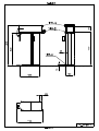
DATI TECNICI, QUOTE DI INGOMBRO,
ALLACCIAMENTI.........................................10-1
CAPITOLO 2....................................................2-1
CAPITOLO 11................................................11-1
IDENTIFICAZIONE DELLA MACCHINA..2-1
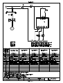
SCHEMI ELETTRICI....................................11-1
CAPITOLO 3. .....................................................3-1 INSTALLAZIONE ............................................. 3-1 IMBALLO ................................................................ 3-1 TRASPORTO ........................................................... 3-1 DISIMBALLAGGIO DELLA MACCHINA ........... 3-1 ALLACCIAMENTO VAPORE E RITORNO
CONDENSA............................................................. 3-1 COLLEGAMENTO ELETTRICO ........................... 3-2 CAPITOLO 12.................................................12-1
SCHEMI PNEUMATICI................................12-1
CAPITOLO 13................................................13-1
DISEGNI PEZZI DI RICAMBIO..................13-1
USO DELLA MACCHINA ................................ 3-2 VERIFICHE PRELIMINARI ................................... 3-2 ACCENSIONE MACCHINA................................... 3-2 CICLO DI STIRATURA .......................................... 3-2 USO DEL TASTO
...................................... 3-2 USO DELLA SCHEDA ELETTRONICA........ 3-2 OPERAZIONI DA COMPIERE AL TERMINE
DEL LAVORO .................................................... 3-3 MANUTENZIONE ............................................. 3-4 MANUTENZIONE SEMESTRALE/ANNUALE .... 3-4 GUASTI ............................................................... 3-5 GUASTI SUBITO DOPO L’INSTALLAZIONE ..... 3-5 GUASTI AL VENTILATORE ................................. 3-5 GUASTI AL CIRCUITO DI VAPORIZZAZIONE . 3-5 MODALITÀ RICHIESTA PEZZI DI
RICAMBIO ......................................................... 3-6 ACCANTONAMENTO O DEMOLIZIONE ... 3-6
CAPITOLO 14................................................14-1
DISTINTE CODICI.........................................14-1
EN
i:\gestione istruzione\_topper\mp\_4mp_en.doc (marzo 02)
I N D E X
CHAPTER 1...................................................1-1
SAFETY PRECAUTIONS.............................1-1
CHAPTER 10...............................................10-1
TECHNICAL SPECIFICATIONS,
ENCUMBRANCE, CONNECTIONS..........10-1
CHAPTER 2...................................................2-1
MACHINE IDENTIFICATION…….............2-1
CHAPTER 11-..............................................11-1
ELECTRICAL DIAGRAMS……................11-1
CAPITOLO 4 ......................................... DFDGDHH4-1 INSTALLATION ................................................ 4-1 PACKING................................................................. 4-1 TRANSPORT ........................................................... 4-1 UNPACKING OF THE MACHINE ......................... 4-1 STEAM AND CONDENSATION RETURN
CONNECTION ........................................................ 4-1 ELECTRICAL CONNECTION ............................... 4-1 USE OF THE MACHINE .................................. 4-2 PRELIMINARY CONTROLS ................................. 4-2 START-UP OF THE MACHINE ............................. 4-2 PROCESS FOR FINISHING CYCLE ...................... 4-2 USING THE
KEY....................................... 4-2 USING THE CONTROL PANEL ..................... 4-2 SHUTTING DOWN OF THE MACHINE ....... 4-3 MAINTENANCE ................................................ 4-3 SIX MONTHLY / YEARLY MAINTENANCE ...... 4-4 BREAKDOWNS ................................................. 4-4 IMMEDIATELY FOLLOWING INSTALLATION 4-4 PROBLEMS WITH THE FAN ................................ 4-4 PROBLEMS WITH THE STEAM CIRCUIT .......... 4-4 ORDERING SPARE PARTS ............................ 4-5 STORAGE OR DEMOLITION ........................ 4-5 CHAPTER 12................................................12-1
PNEUMATIC DIAGRAMS..........................12-1
CHAPTER 13...............................................13-1
DRAWING OF SPARE PARTS..................13-1
CHAPTER 14...............................................14-1
CODE’S LIST…….......................................14-1
i:\gestione istruzione\_topper\mp\_5mp_fr.doc (dicembre 01)
T A B L E D E S
M A T I E R E S
CHAPITRE 1....................................................1-1
CONSEILS POUR LA SECURITE DES
PERSONNES ET DES CHOSES.....................1-1
FR
CHAPITRE 10................................................10-1
DONNEES TECHNIQUES, COTES D’
ENCOMBREMENT, BRANCHEMENTS….10-1
CHAPITRE 2....................................................2-1
CHAPITRE 11................................................11-1
IDENTIFICATION DE LA MACHINE.........2-1
SCHEMAS ELECTRIQUES..........................11-1
CAPITOLO 5 ......................................................5-1 CHAPITRE 12................................................12-1
INSTALLATION ................................................ 5-1 SCHEMAS PNEUMATIQUES......................12-1
EMBALLAGE .......................................................... 5-1 TRANSPORT ........................................................... 5-1 DEBALLAGE DE LA MACHINE .......................... 5-1 BRANCHEMENT VAPEUR ET RETOUR
CONDENSAT .......................................................... 5-1 BRANCHEMENT ELECTRIQUE ........................... 5-1 CHAPITRE 13................................................13-1
DESSINS PIECES DE RECHANGE.............13-1
USAGE DE LA MACHINE ............................... 5-2 VERIFICATIONS PRELIMINAIRES ..................... 5-2 DEMARRAGE MACHINE ...................................... 5-2 PROCEDURE POUR CYCLE DE REPASSAGE ... 5-2 USAGE DU POUSSOIR
............................. 5-2 USAGE DE LA CARTE ELECTRONIQUE ... 5-2 OPERATIONSA EFFECTUER A LA FIN DU
TRAVAIL ............................................................ 5-3 ENTRETIEN ....................................................... 5-3 ENTRETIEN SEMESTRIEL/ANNUEL .................. 5-4 PANNES .............................................................. 5-5 PANNES IMMEDIATEMENT APRES
L’INSTALLATION .................................................. 5-5 PANNES AU VENTILATEUR................................ 5-5 PANNES AU CIRCUIT DE VAPORISATION ....... 5-5 MODALITES COMMANDE DES PIECES DE
RECHANGE ....................................................... 5-6 STOCKAGE OU DEMOLITION ..................... 5-6 CAPITOLO 14................................................14-1
LISTES DES CODES......................................14-1
DE
I:\gestione istruzione\_Topper\MP\_6mp_DE.doc (dicembre 01)
I N H A L T
KAPITEL 1......................................................1-1
SICHERHEITSHINWEISE FÜR PERSONEN
UND GEGENSTÄNDE ...................................... 1-1
KAPITEL 2............................................... ..........2-1
IDENTIFIZIERUNG DER MASCHINE ...... ...2-1
CAPITOLO 6 ........................................... CVCBN6-1 INSTALLATION ................................................ 6-1 VERPACKUNG ....................................................... 6-1 TRANSPORT ........................................................... 6-1 AUSPACKEN DER MASCHINE ............................ 6-1 DAMPFANSCHLUSS UND KONDENSRÜCKLAUF6-1 ELEKTRISCHER ANSCHLUSS ............................. 6-1 GEBRAUCH DER MASCHINE ....................... 6-2 EINLEITENDE KONTROLLEN ............................. 6-2 INBETRIEBNAHME DER MASCHINE................. 6-2 VORGANG DES BÜGELSZYKLUSSES ............... 6-2 GEBRAUCH DER TASTE
......................... 6-2 GEBRAUCH DER KARTE DES
MIKROPROZESSORS ...................................... 6-2 DURCHZUFÜHRENDE ARBEIT NACH
BEENDIGUNG DES GEBRAUCHS ................ 6-3 WARTUNG ......................................................... 6-4 HALBJÄHRIGE/ JÄHRLICHE WARTUNG .......... 6-4 STÖRUNGEN ..................................................... 6-5 STÖRUNGEN SOFORT NACH DER
INSTALLATION ..................................................... 6-5 STÖRUNGEN AM VENTILATOR ......................... 6-5 STÖRUNGEN AM DAMPFUMLAUF .................... 6-5 BESTELLUNG DER ERSATZTEILE ............. 6-6 BEISEITELEGUNG ODER
VERSCHROTTUNG.......................................... 6-6 KAPITEL 10......................................…........10-1
TECHNISCHE DATEN, RAUMBEDARF,
ANSCHLÜSSE .................................................. 10-1
KAPITEL 11.................................................11-1
ELEKTRISCHER SCHALTPLAN ................. 11-1
KAPITEL 12.................................................12-1
PNEUMATISCHER SCHALTPLAN...........12-1
KAPITEL 13.................................................13-1
ZEICHNUNGEN DER ERSATZTEILE…...13-1
KAPITEL 14...................... ............................ ...14-1
VERZEICHNIS DER CODS ........................... 14-1
ES
I:\gestione istruzione\_Topper\MP\_7mp_ES.doc (dicembre 01)
Í N D I C E
CAPÍTULO 1........................................…........1-1
ADVERTENCIAS PARA LA SEGURIDAD DE
LAS PERSONAS Y DE LAS COSAS..……....1-1
CAPÍTULO 2..................................…..............2-1
IDENTIFICACIÓN DE LA MÁQUINA….....2-1
CAPITOLO 7 ......................................................7-1 INSTALACION .................................................. 7-1 EMBALAJE ............................................................. 7-1 TRANSPORTE ......................................................... 7-1 DESEMBALAJE Y UBICACIÓN DE LA MÁQUINA7-1 CONEXIÓN VAPOR Y RETORNO DE
CONDENSADO ....................................................... 7-1 CONEXION ELECTRICA ....................................... 7-1 CAPÍTULO 10..............................................10-1
DATOS TÉCNICOS, DIMENSIONES,
CONEXIONES………………………..……10-1
CAPÍTULO 11...............................................11-1
ESQUEMAS ELÉCTRICOS ……..………11-1
CAPÍTULO 12...............................................12-1
ESQUEMAS NEUMÁTICOS…………...…..12-1
CAPÍTULO 13...............................................13-1
DIBUJOS DE LOS REPUESTOS.......……...13-1
EMPLEO DE LA MÁQUINA ........................... 7-2 VERIFICACIONES PRELIMINARES .................... 7-2 ENCENDIDO DE LA MÁQUINA........................... 7-2 PROCEDIMIENTO PARA EL CICLO DE
PLANCHADO .......................................................... 7-2 EMPLEO DE LA TECLA
.......................... 7-2 EMPLEO DE LA TARJETA ELECTRÓNICA7-2 OPERACIONES A REALIZAR AL FINAL DEL
TRABAJO ........................................................... 7-3 MANTENIMIENTO .......................................... 7-4 MANTENIMIENTO SEMESTRAL/ANUAL .......... 7-4 AVERÍAS ............................................................ 7-5 AVERÍAS INMEDIATAMENTE DESPUÉS DE LA
INSTALACIÓN........................................................ 7-5 AVERÍAS EN EL VENTILADOR .......................... 7-5 AVERIAS EN EL CIRCUITO DE VAPOR ............. 7-5 MODALIDAD PARA EL PEDIDO DE
REPUESTOS ....................................................... 7-6 ALMACENAJE O DEMOLICIÓN .................. 7-6 CAPÍTULO 14...............................................14-1
LISTAS DE LOS CÓDIGOS.....…..............14-1
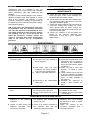
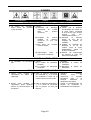
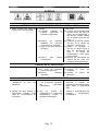
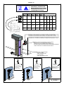
CAPITOLO 1 – CHAPTER 1 - CHAPITRE 1 – KAPITEL 1 – CAPÍTULO 1
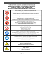
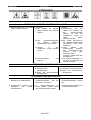
SEGNALI DI PRESCRIZIONE, PERICOLO E INDICAZIONE
PRESCRIPTION, DANGER AND INDICATION SIGNALS
SIGNAUX DE PRESCRIPTION, DANGER ET INDICATION
VERBOTS-, GEBOTS- UND WARNZEICHEN
SEÑALES DE PRESCRIPCIÓN, PELIGRO Y INDICACIÓN
Divieto di togliere i carter di protezione con impianto funzionante.
Do not remove protection covers when machine is working.
Défense d’enlever les couvercles de protection pendant le fonctionnement de la machine.
Abnahme der Schutzgehäuse bei anlaufender Anlage verboten.
Prohibido quitar la tapa de protección durante el funcionamiento de la maquina.
Divieto di eseguire interventi di manutenzione a macchina in moto.
Do not effect maintenance when machine is working.
Défense d’exécuter toutes entretiens pendant le fonctionnement de la machine.
Wartungseinsätze bei anlaufender Anlage verboten.
Prohibido efectuar todos mantenimientos durante el funcionamiento de la maquina.
Vietata l’apertura del quadro elettrico al personale non autorizzato.
Authorized personnel only can open the electric panel.
Défense d’ouvrir le cadre électrique par le personnel non autorisé.
Öffnung des Gehäuses für Unbefugte verboten.
Prohibido abrir el tablero eléctrico para obreros no autorizados.
Vietato utilizzare acqua per spegnere l’incendio.
Do not extinguish with water.
Défense d’eteindre avec de l’eau.
Mit Wasser löschen verboten.
Prohibido apagar con agua.
Obbligo di riposizionare i carter di protezione prima di azionare l’impianto.
Protection covers must be put on before using the machine.
Il est obligatoire de remettre le couvercle de protection avant d’actionner la machine.
Vor Inbetriebsetzung der Anlage Schutzgehäuse wiedereinbauen.
Está obligatorio reponer las tapas de protección antes que se ponga en marcha la maquina.
Consultare il manuale d’uso, lo schema elettrico e le procedure.
Consult the instruction’s manual, the electric diagram and procedures.
Consulter le manuel d’emploi.
Betriebsanweisung, Schaltschema und Vorgänge lesen.
Consultar el manual d’empleo.
Attenzione pericolo di scottature alle mani!
High temperatures! Possibility of burning!
Hautes températures! Danger de brûlures!
Warnung vor Handverbrennungen!
Temperaturas elevadas! Peligro de quemaduras!
Quadro in tensione.
Danger: electricity.
Danger électrique.
Warnung vor gefährlicher elektrischer Spannung 380 V.
Peligro: Tensión eléctrica.
Pag. 1-1
CAPITOLO 1 – CHAPTER 1 - CHAPITRE 1 – KAPITEL 1 – CAPÍTULO 1
recueil désigné pour le recyclage des rebuts électriques
et électroniques.
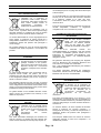
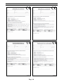
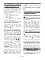
INFORMAZIONI PER LO SMALTIMENTO
DELL’APPARECCHIATURA
L’etichetta con il contenitore di
spazzatura mobile barrato presente
sul prodotto, indica che il prodotto non
deve essere smaltito tramite la
convenzionale
procedura
di
smaltimento dei rifiuti domestici.
Per evitare eventuali danni per l’ambiente e per la
salute umana, il prodotto deve essere separato dagli
altri rifiuti domestici e consegnato al punto di raccolta
designato per il riciclo dei rifiuti elettrici o elettronici.
Le recueil diversifié et le recyclage des pièces de rebut
servent pour la conservation des résources naturelles
et à préserver l’habitat et le salut des gens.
L’écoulement abusif du produit sera poursuivi aux
termes de la loi.
Pour tout autre renseignement concernent les points de
recueils disponibles, s’adresser à l’organisme
compétent local ou au revendeur du produit,
INFORMATION ÜBER ENTSORGUNG VON
ALTGERÄTEN
La raccolta differenziata ed il riciclo degli apparecchi di
scarto servirà a conservare le risorse naturali ed a
salvaguardare l’ambiente e la salute delle persone. Lo
smaltimento abusivo del prodotto sarà perseguito a
norma di legge.
Per maggiori dettagli sui centri di raccolta disponibili
contattare l’ente locale competente o il rivenditore del
prodotto.
INFORMATION FOR THE DISPOSAL OF THE
EQUIPMENT
The label showing the crossed mobile
garbage container on the product,
points out that the product must not be
disposed through the conventional
procedure of disposal of the domestic
waste.
To avoid possible damage to the environment and for
improved human health, the product has to be
separated from the other domestic waste and delivered
to the designated collection point for the recycling of
electric or electronic waste.
Das auf dem Produkt befindliche
Etikett, das eine durchgestrichene
Abfalltonne auf Rädern darstellt,
weist auf das Verbot hin, dieses
Produkt als Hausabfall zu entsorgen.
Um
eventuelle
Umwelt–
und
Gesundheitsschäden zu vermeiden, muß das Produkt
von anderen Hausabfällen getrennt werden und zur
Entsorgung an zuständige Recyclingfirmen bzw.
Sammelorte für Elektro- und Elektronik-Altgeräte
übergeben werden.
Die getrennte Sammlung und Recycling der Altgeräte
dient zur Bewahrung des natürlichen Reichtums und
zum Schutz von Umwelt und Gesundheit.
Eine nicht umweltgerechte Beseitigung des Produkts
wird gesetzlich bestraft.
Für weitere Information betreffend der verfügbaren
Sammelorte, wenden sich an die örtliche zuständigen
Behörden oder an Ihren Produkthändler.
INFORMACIONES POR LA LIQUIDACIÓN DE LA
INSTRUMENTACIÓN
The diversified collection and the recycling of rejected
instruments will serve to preserve the natural resources
and to safeguard the environment and the health of the
people. The unauthorized disposal of the product will be
prohibited according to the local laws.
For greater details on the available collection centres
please contact the competent local authority or the
retailer of the product.
RENSEIGNEMENTS POUR L’ECOULEMENT DE LA
MACHINE
La etiqueta con el contenedor de
basura móvil barrato presente sobre
el producto, indica que el producto no
tiene que ser eliminado por el
convencional
procedimiento
de
liquidación
de
los
rechazos
domésticos.
Para evitar eventuales daños por el entorno y por la
salud humana, el producto tiene que ser separado por
los demás rechazos domésticos y remitidos al punto de
colección designado por el reciclo rechazos eléctricos o
electrónicos.
L’Etiquette avec la poubelle barrée
qu’il y a sur le produit, signifie que le
produit même ne peut pas être écoulé
par
le
canal
conventionnel
d’écoulement
des
ordures
domestiques.
La colección distinta y el reciclo aparatos de descarte
servirá a conservar los recursos naturales y a
salvaguardar el entorno y la salud de las personas. La
liquidación abusiva del producto será perseguida a
norma de ley.
Pour éviter d’éventuels dommages pour l’habitat et le
salut de l’homme, la machine doit être séparée des
autres ordures domestiques et livrée jusqu’au point de
Para mayores detalles sobre los centros de colección
disponible contactar al ente local competente o el
detallista del producto.
Pag. 1-4
CAPITOLO 1 – CHAPTER 1 - CHAPITRE 1 – KAPITEL 1 – CAPÍTULO 1
Pag. 1-4
CAPITOLO 1 – CHAPTER 1 - CHAPITRE 1 – KAPITEL 1 – CAPÍTULO 1
Pag. 1-4
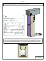
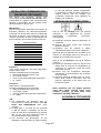
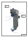
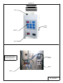
Capitolo 2
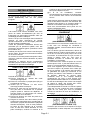
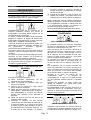
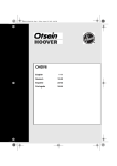
IDENTIFICAZIONE DELLA MACCHINA - IDENTIFICATION OF THE MACHINE - IDENTIFICATION DE LA MACHINE
IDENTIFIZIERUNG DER MASCHINEN - IDENTIFICATIÓN DE LA MAQUINA
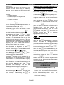
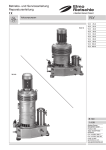
COPIA TARGHETTA DATI TECNICI E' RIPORTATA SULLA COPERTINA DI QUESTO MANUALE
COPY OF THE TECHNICAL SPECIFICATIONS PLATE IS REPRODUCED ON THE COVER OF THIS MANUAL
COPIE DE LA PLAQUE DES DONNEES TECHNIQUES EST REPRODUITE SUR LA COVERTURE DE CE MANUEL
KOPIE DES TECNHISCHEN-DATEN ETIKETTE IST AUF DEN UMSCHLAG DIESER ANLEITUNG REPRODUZIERT
COPIA TARJETA DATOS TECNICOS ES REPRODUCIDA SOBRE EL FORRO DE ESTO MANUAL
M_00555/1
Pag.2-1
ITA L IANO
CA PITOLO 3
Capitolo 3 .
INSTALLAZIONE
IMBALLO
La macchina può essere imballata in tre modi:
1) CON FONDALE IN LEGNO E MACCHINA
AVVOLTA IN CELLOPHANE: formato da un
fondale (che ne permette il sollevamento e lo
spostamento con mezzi meccanici (paranchi,
muletti). La macchina, imbullonata sul fondale
nei piedini d’ancoraggio, è avvolta con un
sacco di polietilene (PE) fissato con graffette
sul fondale.
2) CON INDUPACK: con l’aggiunta di un
involucro in cartone bloccato con regge
metalliche su pallet.
3) SOLO INCARTATURA
ITA L IANO
possono cadere danneggiando cose, persone
o animali.
e) Togliere i bulloni che fissano i piedini della
macchina sul fondale.
f) Imbragare la macchina con due funi (verificare
che siano idonee al peso totale della macchina
rilevabile dal cartellino dati tecnici), l'una nella
parte posteriore, l'altra nella parte anteriore
della macchina; quindi, con l'ausilio di un
muletto o paranco mecca-nico, sollevare la
macchina e posizionarla nel luogo destinato
all'installazione senza più muoverla con
braccia umane.
g) Al termine dell'installazione rimontare con cura
i pannelli e le protezioni della macchina
assieme agli accessori in dotazione.
Devono essere osservate alcune misure di
distanza dalle pareti e dalle altre macchine, al fine
di garantire una lavorazione più scorrevole ed una
perfetta manutenzione. La macchina non
necessita di alcun ancoraggio al pavimento. Si
raccomanda di sistemarla perfettamente in piano.
TRASPORTO
Subito al ricevimento della macchina imballata,
notificare per scritto al trasportatore eventuali
danni subiti dall’imballo durante il trasporto.
Infatti, qualora tali danni abbiano interessato
anche la macchina, l’assicurazione del corriere
risponderà solo se tali danni presunti sono stati
subito segnalati.
Tutte le operazioni di installazione devono essere
eseguite da personale qualificato, munito delle
necessarie
protezioni
(guanti,
protezioni
antinfortunistiche ecc.).
Non usare getti di acqua contro la macchina per
nessun motivo ed evitare bruschi movimenti o urti
violenti.
La macchina non deve essere trasportata da
braccia umane, bensì con l'ausilio di muletti o
paranchi meccanici.
Trasportare la macchina completa di imballo nel
luogo più prossimo al punto di installazione e
procedere al suo disimballaggio.
DISIMBALLAGGIO DELLA MACCHINA
Procedere nel seguente modo:
a) Togliere, se esistente, l’indupack munendosi di
appositi attrezzi meccanici.
b) Togliere la copertura in polietilene (PE) che
avvolge la macchina.
c) Verificare che la macchina non abbia subito
danneggiamenti durante il trasporto.
d) Asportare dal fondale tutti gli accessori che
non sono fissati o imbullonati sul bancale
perché, spostando la macchina dal bancale,
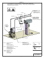
ALLACCIAMENTO VAPORE E
RITORNO CONDENSA
(VEDI DISEGNI A PAG. 10-4)
E’ necessario effettuare un collegamento
tradizionale, cioè con scaricatore di condensa,
come illustrato nel disegno di pag. 10-4.
Per quest’ultimo tipo di collegamento, derivare
dalla parte alta della conduttura centrale di vapore
un tubo di ferro da 1/2" GAS e farlo arrivare a 100
cm dalla macchina.
All’estremità di questo tubo montare un rubinetto a
sfera “POS. 67”, onde poter escludere la
macchina dall’impianto.
Il collegamento del rubinetto a sfera al raccordo
entrata vapore “POS. 4” si può fare con un tubo di
rame avente un diametro interno di 14 mm.
Vi ricordiamo che la macchina funziona con
vapore alla pressione di 4 - 6 bar (58 - 87 psi)
perciò, se la macchina viene allacciata ad un
generatore di vapore funzionante ad una
pressione più elevata, è necessario installare un
riduttore di pressione.
Collegare al raccordo ritorno condensa “POS. 3”
uno scaricatore di condensa da 1/2" GAS a
secchiello rovesciato con filtro (SPIRAX SARCO
HM 007 oppure JUCKER SA8).
A valle dello scaricatore si deve montare una
valvola di ritegno a clappè onde evitare
contropressioni allo scaricatore.
E’ indispensabile montare un rubinetto a sfera
sulla tubazione di ritorno condensa “POS. 68”
Pag. 3-1
ITA L IANO
CA PITOLO 3
ITA L IANO
(tubo da 1/2" GAS) onde permettere l’esclusione
della macchina dall’impianto.
PROCEDIMENTO PER CICLO DI
STIRATURA
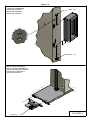
COLLEGAMENTO ELETTRICO
a) Tirare in avanti il cavallotto tendi bacino fino a
farlo agganciare.
b) Infilare il pantalone sulla forma di stiratura e
dopo aver abbottonato il primo bottone
dell’apertura anteriore premere il pulsante di
sgancio cavallotto che mette in tensione il
bacino.
c) Fissare il pantalone mediante l’apposita pala.
d) Chiudere la parte inferiore delle gambe del
pantalone con le pinze.
e) Avviare il ciclo di stiratura premendo il pedale
(per le impostazione del ciclo di stiratura vedi
“Uso della scheda”).
f) Al termine del ciclo togliere il pantalone.
(VEDI DISEGNO A PAG. 10-6)
Accertarsi che la tensione e frequenza di linea
corrispondano a quelle segnate sulla targa dati
tecnici della macchina (vedere pag. 2-1).
Per voltaggi 400V/3 e 440V/3, predisporre una
linea elettrica trifase con neutro e terra e
collegarla ai morsetti entrata corrente (bloccare il
cavo nel pressacavo “POS. 8”).
Per gli altri valori di voltaggio e per il
dimensionamento della linea e dell’interruttore,
vedere la tabella riportata nel disegno.
La linea di corrente dovrà essere dotata di un
interruttore
automatico
magnetotermico
differenziale da 30 mA, con presa e spina ad
interblocco meccanico.
Si fa obbligo, pena la decadenza della garanzia, di
collegare la macchina ad una buona messa a
terra secondo le normative vigenti.
Controllare, prima del collaudo iniziale, che i
morsetti di tutti i componenti elettrici non si siano
allentati durante il trasporto.
Dopo il collegamento, verificare il senso di
rotazione dei motori (ventilatori) e, qualora fosse
errato, invertire tra loro due delle tre fasi in
ingresso.
Rimontare tutte le pannellature e le protezioni
della macchina.
USO DEL TASTO
Premendo una sola volta il tasto
possibile arrestare il ciclo di stiratura.
, e’
USO DELLA SCHEDA
ELETTRONICA
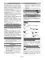
Per la stiratura procedere come segue: impostare
il ciclo di stiratura selezionando il programma
desiderato, come illustrato nel paragrafo
successivo.
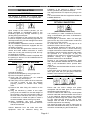
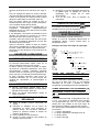
Esempio di scelta tempi di stiratura:
1° tempo
0
5
10
2° tempo
USO DELLA MACCHINA
0
VERIFICHE PRELIMINARI
Controllare che i rubinetti a sfera montati sulle
tubazioni di alimentazione vapore “POS. 67” e
ritorno condensa “POS. 68” siano aperti.
Inizialmente, con la macchina fredda, il vapore in
arrivo si condenserà rapidamente; è, quindi,
consigliabile attendere qualche minuto prima di
iniziare la lavorazione, affinché tutta la condensa
formata si possa scaricare.
Non attenendovi a questa norma, l’abbondante
condensa che si forma uscirebbe dalle tubazioni
di vaporizzazione, danneggiando il capo.
ACCENSIONE MACCHINA
a) Accendere l’interruttore generale previsto
sulla linea elettrica di alimentazione e
l’interruttore
generale
della
macchina
“POS.69”.
b) Aprire le saracinesche di alimentazione
vapore e ritorno condensa.
5
3° tempo
0
5
4° tempo
0
5
10
15 20
USO DEI TASTI
E
(PARTENZA CICLO
E VISUALIZZAZIONE DEI PROGRAMMI DI
STIRATURA)
Accendendo l’interruttore generale della macchina
“POS. 69” (vedi pag. 10-2, fig. 2), s’illuminerà il
display
della
scheda:
comparirà
l’ultimo
programma di stiratura completamente svolto.
Pag. 3-2
ITA L IANO
COME
CA PITOLO 3
MEMORIZZARE
I
PROGRAMMI
STIRATURA (USO DEI TASTI
e
DI
).
E’ possibile memorizzare 10 programmi: da ”P0“ a
”P9“. I tempi di stiratura dei primi cinque
programmi (da “PO” a “P4”) sono già pronti per
essere utilizzati e comunque possono essere
modificati in qualsiasi momento.
I quattro tempi visualizzabili in successione sono i
seguenti:
1° tempo: vaporizzazione,
2° tempo: vaporizzazione misto ad aria,
3° tempo: pausa,
4° tempo: asciugamento.
Per
far
scorrere
l’elenco
dei
programmi
.
memorizzati, premere il tasto
Per accedere alla variazione dei tempi di stiratura
di un programma, occorre posizionarsi
sul
programma desiderato. (esempio “P0”).
ITA L IANO
tasto
per determinare la partenza del ciclo di
stiratura.
Se si volesse interrompere il ciclo di stiratura
prima che sia ultimato, occorre ripremere il tasto
.
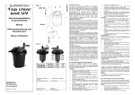
USO DELLA FUNZIONE ARIA MANUALE
VENTILATORE INTERNO ON/OFF
:
Il tasto
avvia il ventilatore soffiando aria calda
nel capo contemporaneamente accenderà la spia
. Tale funzione viene usata quando occorre
prolungare il tempo d’asciugamento del ciclo in
corso, oppure quando il capo deve essere
solamente asciugato.
Premendo il tasto
una prima volta, il
ventilatore si avvia; premendo nuovamente lo si
Premere una prima volta il tasto
per
visualizzare
il
tempo
di
vaporizzazione
(contemporaneamente inizierà a lampeggiare la
arresta. Premendo il tasto
durante il
conteggio del tempo T4, si predisporrà la
macchina per continuare la fase di ventilazione al
termine del conteggio del tempo d’asciugamento
spia del vapore
sino a quando si premeranno i tasti
).
Agendo sui tasti
e
si potrà impostare il
valore del tempo di “vaporizzazione” desiderato:
da 0 a 99 secondi si potrà variare il tempo di 1
secondo per volta, mentre oltre i 99 secondi si
visualizzerà un minuto e quaranta secondi (1.40)
e si potranno impostare i tempi ad intervalli di 10”
(1’.50”, 1’.60”…) sino ad un massimo di nove
minuti e cinquanta secondi (9’.50”). Impostato il
tempo di “vaporizzazione”, premere il tasto
per confermarlo e poter visualizzare il tempo di
“vapore misto ad aria”, contemporaneamente
inizieranno a lampeggiare le spie
e
.
se si volesse memorizzare la funzione
manuale per i cicli successivi).
USO DELLA FUNZIONE VAPORE MANUALE
:
Con macchina inattiva, premendo il tasto
si
aziona la vaporizzazione (contemporaneamente
si accenderà la spia
premeranno i tasti
Agendo sui tasti
e
si potrà impostare il
valore del tempo desiderato.
Premere il tasto
per confermare il valore del
tempo
impostato
e
poter
accedere
all’impostazione del tempo di “pausa”; continuare
la medesima procedura sino al tempo di
“asciugamento”.
Terminata l’impostazione dell’ultimo tempo,
premendo un’ultima volta il tasto
si
confermerà il valore del tempo impostato e si
uscirà dalla programmazione dei tempi di
stiratura.
Quando si è selezionato il programma di stiratura
necessario, premere il pedale “POS. 53” oppure il
(oppure
) sino a quando si
oppure
. Premendo
il tasto
durante il conteggio del tempo di
vaporizzazione, si predisporrà la macchina per
continuare la fase di vaporizzazione al termine del
conteggio del relativo tempo sino a quando si
premerà il tasto
(oppure
se si volesse
memorizzare la funzione manuale per i cicli
successivi); il ciclo poi continuerà le altre 3 fasi.
OPERAZIONI DA COMPIERE AL
TERMINE DEL LAVORO
(VEDI DISEGNI A PAGG. 10-3)
a) Chiudere le due saracinesche poste sulle
tubazioni di alimentazione vapore “POS.67” e
ritorno condensa “POS.68”.
Pag. 3-3
ITA L IANO
CA PITOLO 3
b) Disinserire L’ interruttore generale della
macchina “POS. 69”, e l’interruttore generale
previsto sulla linea d’alimentazione.
MANUTENZIONE
Quanto segue è di vitale importanza per avere
una macchina sempre in perfetta efficienza, che vi
darà sempre il massimo rendimento, evitandovi
dispendiosi fermi-macchina.
La prima parte di questa rubrica è divisa in capitoli
a seconda della maggiore o minore frequenza
delle singole manutenzioni.
N.B.: la frequenza da noi indicata (settimanale,
mensile, ecc.) è indicativa e si riferisce ad una
macchina che lavori in condizioni “normali”.
Sarete poi Voi stessi a stabilire l’esatta cadenza
delle operazioni di manutenzione, in funzione dei
seguenti parametri:
Quantità di lavoro eseguito dalla macchina;
Durezza dell’acqua, che causa maggiori o
minori depositi di calcare sugli elementi
riscaldanti della caldaia;
Pulviscolo nell’aria;
Altre particolari condizioni.
Tutte le operazioni di manutenzione vanno
eseguite a macchina completamente spenta ed in
particolare:
a) L’interruttore generale previsto sulla linea
elettrica deve essere spento e la spina deve
essere tolta dalla presa.
b) Devono essere chiusi i rubinetti a sfera
d’alimentazione vapore “POS. 67” e ritorno
condensa “POS. 68” (vedi pag. 10-4).
c) Bisogna lasciare raffreddare le parti calde della
macchina (tubi interni, valvole, ecc.) al fine di
non ustionarsi.
ITA L IANO
Solo seguendo tutte queste precauzioni ed altre
dettate da particolari condizioni contingenti, è
possibile eseguire le manutenzioni sulla macchina
in assoluta sicurezza, ricordandosi che “la
prudenza non è mai troppa”.
Per rendere più evidenti i pericoli, abbiamo posto
nei punti critici della macchina, dei simboli adesivi
il cui significato viene spiegato dettagliatamente
nella pagina rossa all'inizio di questo manuale
(“Segnali di prescrizione, pericolo e indicazione”).
N.B.: in ogni caso, le manutenzioni devono
essere effettuate solo ed esclusivamente da
personale competente, il quale risponde in
prima persona dell'incolumità propria e di altre
persone/animali/cose
eventualmente
interessate. La legge, e specialmente le ultime
direttive CEE, puniscono severamente il
proprietario della macchina qualora faccia
eseguire manutenzioni a personale non
competente.
MANUTENZIONE
SEMESTRALE/ANNUALE
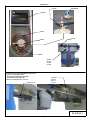
a) Pulire il filtro posto sulla tubazione di ritorno
condensa che, se sporco, ne impedisce lo
scarico e favorisce i risucchi d’acqua.
b) Pulire il condotto ventilazione aria e la batteria
del vapore da eventuali ostruzioni (lanetta,
sporcizie) che ostruiscono il flusso di aria
durante la fase di ventilazione.
c) Controllare le varie giunzioni e rubinetti a
sfera in quanto, in seguito al continuo
riscaldamento e raffreddamento, si possono
verificare delle perdite. In questo caso si
consiglia di smontare le giunzioni, i rubinetti a
sfera e ripristinare la tenuta.
d) Controllare lo stato di conservazione di tutte le
targhette della macchina (di pericolo o di
istruzione). Qualora fossero deteriorate, è
indispensabile
procedere
alla
loro
sostituzione.
Pag. 3-4
ITA L IANO
CA PITOLO 3
ITA L IANO
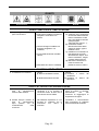
GUASTI
Inconvenienti:
Cause:
Rimedi:
GUASTI SUBITO DOPO L’INSTALLAZIONE
1. Rimedi:
1. Vapore bagnato anche dopo i 1. Cause:
a) Verificare che lo scaricatore
primi cicli di lavoro.
a) Scaricatore installato in posizione
sia montato sulla tubazione
sbagliata o scaricatore non
ritorno condensa e sia del
idoneo;
tipo a secchiello rovesciato
(vedi paragrafo
“Allacciamento vapore...”);
b) Controllare l’esatta
direzione del flusso della
b) Valvola di ritegno installata con
valvola di ritegno, oppure
direzione sbagliata o non
installarne una;
installata;
c) Installare uno scaricatore a
fine tubazione tra il tubo
c) Acqua nella tubazione mandata
alimentazione vapore ed il
vapore;
ritorno condensa o, meglio,
a monte della macchina;
d) Eliminare le sifonature in
modo da creare una
pendenza verso lo scarico.
d) Sifonature tubo ritorno condensa.
GUASTI AL VENTILATORE
1. Il ventilatore non funziona.
1. Cause:
a) Motore ventilatore bruciato;
b) Bobina teleruttore bruciata;
1. Rimedi:
a) Sostituire il
ventilatore;
b) Sostituire la
teleruttore;
motore
del
bobina
del
GUASTI AL CIRCUITO DI VAPORIZZAZIONE
1. Perdite d’acqua durante la 1. Nel serbatoio separatore di 1. Attendere
qualche
minuto
fase
di
vaporizzazione
condense vi è un accesso di
prima di iniziare a lavorare,
all’inizio della stiratura.
condensa dovuto al fatto che la
permettendo
così
alla
macchina è ancora fredda.
macchina di raggiungere la
temperatura di regime.
2. Perdite d’acqua durante la 2. Nel serbatoio separatore vi è un 2. Controllare il funzionamento
fase
di
vaporizzazione
accesso di condensa che lo
dello scaricatore di condensa
dopo
qualche
ora
di
scaricatore
non
riesce
a
ed eventualmente sostituirlo.
funzionamento
della
scaricare.
macchina.
Pag. 3-5
ITA L IANO
CA PITOLO 3
impegnativi. La fabbrica si riserva il diritto di
apportare, in qualsiasi momento, tutti i
cambiamenti che riterrà opportuni, senza
l’obbligo di aggiornare il presente opuscolo.
MODALITÀ RICHIESTA PEZZI DI
RICAMBIO
I ricambi devono essere ordinati esclusivamente
tramite fax, utilizzando l’apposito modulo “R1”
allegato e fornendo tutti i dati in esso richiesti, al
fine di poter garantire l’invio dei pezzi in tempi
brevi.
IMPORTANTE:
Per i componenti elettrici con tensione e
frequenza diverse da 220V/230V/240V 50Hz. (dati
da confrontare con quelli della targhetta
dell'articolo guasto) far seguire al codice di
ordinazione la lettera corrispondente alla tensione
desiderata, come da seguente tabella:
A
B
C
D
E
F
G
H
I
L
M
220V/230V 60Hz.
240V 50Hz.
200V 50Hz.
200V 60Hz.
190V 50Hz.
115V 60Hz.
110V 60Hz.
208V 50Hz.
24V 50Hz.
240V 60Hz.
254V 50Hz.
ITA L IANO
ACCANTONAMENTO O
DEMOLIZIONE
In caso di accantonamento per lungo periodo,
occorre scollegare le fonti di alimentazione
idrauliche, elettriche, pneumatiche.
a) Scaricare l’eventuale serbatoio separatore
condense.
b) Pulire i vari tubetti da eventuali tamponi di
calcare.
c) Richiudere tutti i rubinetti a sfera di
alimentazione vapore e di ritorno condensa.
Rimontare tutte le pannellature di chiusura della
macchina e rivestirla con un telo per proteggerla
dall'umidità e dalla polvere.
Esempio 1:
Occorre una bobina teleruttore a 230V 50 Hz.
Dati completi per l’ordine:
Macchina Modello: Manichino Tipo ...
Matricola N° 110227
Codice 04775-bobina teleruttore 230V/50 Hz
1 pezzo
Esempio 2:
Stessa bobina, ma a 254V/50Hz.
Dati completi per l’ordine:
Macchina Modello: Manichino Tipo ...
Matricola N° 110228
Codice 04775/M-bobina teleruttore 254V/50
Hz
1 pezzo
In caso di demolizione agire nel seguente modo:
a) Scaricare direttamente nella fognatura l’acqua
rimasta nel serbatoio recupero condense,
assicurandosi che siano privi di impurità
nocive.
b) Rimuovere tutta la componentistica, elettrica,
idraulica e pneumatica, dai pannelli su cui è
fissata.
c) Raccogliere plastica, bachelite, ghisa, ferro,
rame, ottone, acciaio, stoffe, gomma ecc.
negli appositi contenitori e smaltirli secondo le
norme vigenti.
Sperando che queste pagine possano
esserVi utili come ci siamo ripromessi,
non ci rimane che augurarVi BUON
LAVORO!
N.B.:
1. I particolari che compaiono su questo manuale
senza il numero di codice a fianco, NON
SONO DISPONIBILI a magazzino.
2. La sigla “POS. 1” oppure “POS. 25” ecc. che
compare a fianco di alcuni particolari, non ha
nulla a che vedere con il codice di quel
particolare e quindi non deve essere citata
nell’ordinazione dei ricambi.
3. I dati, le descrizioni e le illustrazioni contenuti
nel presente opuscolo non sono in alcun modo
Pag. 3-6
L’UFFICIO TECNICO
ENGLISH
CHAPTER 4
Capitolo 4 dfdgdhh
INSTALLATION
PACKING
The machine is packed into a special export
cartoon (INDUPACK) fixed on a fumigated pallet.
ENGLISH
installation of the machine in order to ensure
smooth operation and good maintenance.
The equipment does not require any fixing to the
floor.
It is recommended that the equipment should be
installed dead level
TRANSPORT
STEAM AND CONDENSATION
RETURN CONNECTION
Upon receipt of the machine packed, you are
kindly requested to immediately report to the
forwarding agent any damage suffered by the
packing during the transport.
In case of damages to the machine as well, the
insurance company of the forwarding agent will be
held responsible only if these damages have been
reported immediately.
All the installation operations must be undertaken
only by competent personnel equipped with the
necessary protection.
Do not use water jets against the machine for any
reason and avoid sudden movement or violent
blows. Do not carry the machine by hand, but only
by forklift truck or tackle.
It is advisable to move the machine complete with
the packing to where it is to be installed and then
unpack the machine.
(SEE DRAWING PAGE 10-4)
UNPACKING OF THE MACHINE
Proceed as following:
a) Remove the indupack by using proper tools.
b) Remove the plastic protection.
c) Verify that the machine has not suffered
damages during the transport.
d) Take away from the pallet all the accessories
not fixed or bolted, as they can damage
property, persons or animals when falling
down.
e) Remove the bolts fixing the machine to the
pallet
f) Sling the machine by means of two ropes
(verify that are suitable for the total weight of
the machine), one at the rear and the other at
the front side of machine; then lift it by means
of forklift truck or tackle and place it where it
must be installed, without moving it by hand.
g) When installation has been completed,
carefully refit all the panels, protection devices
and the accessories.
Various distances from the walls and other
equipment must be observed during the
It is necessary to make a traditional connection,
using a condensation gate valve, as illustrated in
Drawing page 10-4.
For this type of connection, take a 1/2" steel gas
pipe from the top of the central steam conduit and
fit it 100 cm from the machine.
Fit a ball valve “POS. 67” to this pipe so as to
isolate the machine from the plant.
The connection between the ball valve and the
machine steam input “POS. 4” can be made using
a copper tube with an internal diameter of 14 mm.
Remember that the machine operates with steam
at a pressure of 4 - 6 bars (58 - 87 psi), and
therefore, if the machine is connected to a steam
generator working at a higher pressure, a
pressure reducer has to be installed.
Connect a 1/2" basin-type condensation, fitted
with a filter (SPIRAX SARCO HM 007 or JUCKER
SA8), to the condensation return junction drain
“POS. 3”.
A gate valve must be fitted after the drain to avoid
back pressure.
A ball valve must be fitted on the condensation
return pipe “POS. 68” (1/2" gas pipe) to allow the
isolation of the machine from the plant.
ELECTRICAL CONNECTION
(SEE DRAWING PAGE 10-6)
Ensure that the mains voltage and phase
correspond with the data given on the machine
specification plate (see page 2-1).
In case of 400V/3 and 440V/3 lay a three phase
electrical cable with neutral and earth and connect
it to the electrical clamps fitted to the machine
(clamp the cable through the rubber holder “POS.
8”). The cable and the switch in case of other
voltages must be sized in accordance with the
schedule reported on the drawing.
The electrical supply line must be fitted with an
automatic differential heat safety cut-out switch 30
mA with a mechanical plug and socket block.
Page 4-1
ENGLISH
CHAPTER 4
The machine as per the rules in force must be
connected to a good earth, or the guarantee will
not be honoured. Before first testing the machine,
check that none of the electrical connectors have
worked loose during transport.
After connection to the electricity supply, check
the rotation direction of the motors (fan).
If the direction is wrong, invert the connection of
two of the three phases supply wires.
Replace all the panels and protection devices
when the electrical connections have been
completed.
ENGLISH
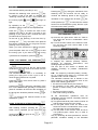
Examples of finishing times:
1° time
0
5
10
2° time
0
5
3° time
0
USE OF THE MACHINE
PRELIMINARY CONTROLS
4° time
0
Check that the ball valves fitted on the steam pipe
“POS. 67” and on the condensation return pipe
“POS. 68” are open.
At first, when the machine is cold, the steam will
condense rapidly and it is therefore advisable to
wait a few minutes before starting work so that the
condensation can be drained off.
If this is not done, condensation formed will
emerge from the steam pipes, damaging the
garments being processed.
START-UP OF THE MACHINE
PROCESS FOR FINISHING CYCLE
a) Pulling the waist expander until hockey to the
latch.
b) Position the trousers on the waist shape,
button the first button of the fly opening and
press the push button which releases the
waist expander and tensions the topper.
c) Hold the trousers by meand of the proper
clamp.
d) Close the bottom of the trouser leg by means
of the springs.
e) Start the finishing program by press the pedal
(for finishing cycle setting see “Using the
control panel”).
f) At the end of the cycle, remove the trousers
from the steam/air former.
KEY
By pressing one only time the
possible to stop the finishing cycle.
5
10
15 20
USE OF THE
AND
KEYS (STARTING
THE CYCLE AND VISUALISING THE IRONING
PROGRAMS)
Turn on the main switch “POS. 69” (see page 102, fig. 2), which will light up the display of the
control panel. The last complete ironing program
will appear.
HOW TO MEMORISE IRONING PROGRAMS
a) Turn on the general electrical supply switch
and the main switch of the machine “POS.69”.
b) Open the mains water gate valve for steam
feeding and condensate return.
USING THE
5
(USE OF THE
USING THE CONTROL PANEL
For the finishing proceed as follows:
Select the program requested as described in the
following section.
KEYS).
It is possible to memorise 10 programs: from ”P0“
to ”P9“. The ironing times of the first five programs
(from “PO” to “P4”) are ready to be used and
however they can be modified at any moment.
The four times successively visualized are the
following:
1° time: steaming,
2° time: steaming mixed with air,
3° time: pause,
4° time: drying.
To see the complete list of programs in the
memory press the
key.
To be able to access to the variation of the ironing
times of a program, it is necessary to position on
the requested program (example "P0").
Press a first time the
key to visualize the
steaming time (at the same time the steam
warning light
key, it is
AND
will begin to light).
and
keys it is
By operating on the
possible to plan the value of the requested
“steaming” time: from 0 to 99 seconds, the time
can be varied of 1 second at a time, while over 99
seconds, one minute and forty seconds will be
visualized (1.40) and the times can be planned to
intervals of 10" (1' .50", 1' .60"..) till a maximum of
Page 4-2
ENGLISH
CHAPTER 4
nine minutes and fifty seconds (9' .50").
Planned the “steaming” time, press the
key
to confirm it and to be able to visualize the
“steaming mixed with air” time, at the same time
the warning lights
light.
and
Pressing the
key during the calculation of the
steaming time, the machine will be ready to
continue the steaming phase at the end of the
calculation of the relative time till when
key
will begin to
and
keys it is
By operating on the
possible to plan the value of the requested time.
key to confirm the value of the
Press the
planned time and to be able to accede to the
planning of the "pause" time; continue the same
procedure till the "drying" time.
At the end of the planning of the last time, by
key, the value of the planned
pressing the
time will be confirmed and you will go out from the
planning of the ironing times.
When you have selected the desired program,
to memorize the manual
will be pressed (or
function for the subsequent cycles); then the cycle
will continue the other 3 phases.
SHUTTING DOWN OF THE
MACHINE
(SEE DRAWINGS PAGE 10-3)
a) Close the two gate valves “POS. 67” fitted to
the steam line and the condensation return
“POS. 68”.
b) Turn off the main switch of the machine “POS.
69” and then the main switch fitted to the
electricity supply.
MAINTENANCE
key to start
press the pedal “POS. 53” or the
the ironing cycle. If you want to stop the ironing
key.
cycle before its completion, press the
USING THE MANUAL AIR FUNCTION
INTEGRATED FAN ON/OFF
:
The
function turns on the fan, which blows
warm air on the item, and at the same time the
will light.
warning light
This function is used when it is necessary to
prolong the drying time of the cycle in use or
when the item needs to be only dried.
key once, the fan turns on; press it
Press the
again and it stops.
key during the calculation of the
Pressing the
time T4, the machine will get ready to continue the
phase of ventilation at the end of the calculation of
the drying time till will be pressed the key
(or
to memorize the manual function for the
subsequent cycles).
USING THE MANUAL STEAM FUNCTION
:
With standing machine, pressing the
key
steam will be operated (at the same time the
will light) till the
warning light
keys will be pressed.
ENGLISH
or
The following instructions are of prime importance
in keeping the machine perfectly efficient,
ensureing its maximum performance, and
avoiding expensive down time.
The first part of this section is divided into
chapters according to periodic maintenance
schedules.
N.B.: The frequency indicated (weekly, monthly,
etc.) is indicative and refers to a machine that
operates under ‘normal’ conditions.
The individual customer has to decide on the
exact frequency of the maintenance work on the
basis of the following guide lines:
the amount of work done by the machine;
the hardness of the water, which causes a
greater or lesser scaling of the boiler heating
element;
the amount of dust in the air;
other local working conditions.
All the maintenance operations must be
undertaken with the machine completely switched
off, and in particular:
a) The general electrical power switch must be off
and the plug removed from the socket;
b) The two gate valves “POS. 67” fitted to the
steam line and the condensation return “POS.
68” (see page 10-4) must be closed.
c) The hot parts of the machine must be left to
cool (internal pipes, valves, etc.) in order to
avoid burns.
Only by observing all these precautions, and the
particular conditions relating to the individual
Page 4-3
ENGLISH
CHAPTER 4
maintenance jobs, is it possible to carry out
maintenance work on the machine with complete
safety. Remember ‘you can never by too
careful’!
In order to make potential dangers more evident,
adhesive symbols have been applied to critical
parts of the machine: the meaning of these
symbols is explained in detail in the red section at
the beginning of this manual (Prescription, danger
and indication signals).
N.B. In any case, the maintenance work must
be undertaken only by competent personnel
who can take personal responsibility for their
own safety and that of other persons, animals
and property. The law, and in particular the
latest EU Directives, severely punish the
owner of a machine who allows maintenance
work to be carried out by non-qualified
personnel
ENGLISH
SIX MONTHLY / YEARLY
MAINTENANCE
a) Clean the filter fitted on the condensation
return pipe that, if dirty, stops drainage and
allows the siphoning back of water.
b) Clean the air pipe and the steam battery from
any impediment (dirty) that stops the air flow
during the ventilation phase.
c) Check the various gaskets and gate valves as
continuous heating and cooling can cause
leaks. Should there be leaks, remove the
gaskets and gate valves and replace with new
to prevent further leaks.
d) Check the condition of all the labels and
plates on the machine (warnings and
instructions). If they are in poor condition,
replace them.
BREAKDOWNS
Problem:
Causes:
Action:
IMMEDIATELY FOLLOWING INSTALLATION
1. Solutions:
1. The steam is wet after the first 1. Causes:
few work cycles.
a) The drain has been installed in a) Check that the gate valve of the
type Spirax Sarco or similar is
the wrong place.
mounted to the condensation
return pipe (see section “Steam
connection” ).
b) The check valve has been b) Check the check valve flow
direction, or install a check
installed in the wrong direction,
valve.
or has not been installed at all.
c) Install a steam trap at the end
c) Water in the steam feed pipe.
of the pipe between the steam
feed pipe and the condensation
return, or better upstream of
the machine.
d) Siphoning in the condensation d) Eliminate the siphoning to
create a slope towards the
return pipe.
drain.
PROBLEMS WITH THE FAN
1. The exhaust fan does not 1. Causes:
1. Solutions:
work.
a) The fan motor is burnt out.
a) Replace the fan motor.
b) Replace the coil of the remote
b) The control switch coil is burnt
control switch.
out.
PROBLEMS WITH THE STEAM CIRCUIT
1. Losses of water at the 1. There is an excess condense in
beginning of the steaming
the separator tank, because the
operation.
machine is cold.
1.
2. Losses of water during the 2. There is an excess condense in
steaming operation, after
the separator tank and the
some hours of working.
discharger cannot discharge.
2.
Page 4-4
Wait some minutes before
beginning work, thus allowing
the machine to reach a steady
temperature.
Check the working of the
condense discharger and if
necessary replace it.
ENGLISH
CHAPTER 4
ORDERING SPARE PARTS
ENGLISH
STORAGE OR DEMOLITION
The spare parts must be ordered only by fax
using the enclosed modulate "R1" complete with
all the data required in order to ensure the rapid
despatch of spare parts.
IMPORTANT
For electrical components other than for
220V/230V/240V 50 Hz supply (check on the
specification plate of the defective part), add to
the order code the letter corresponding to the
rating required as given in the following table:
A
B
C
D
E
F
G
H
I
L
M
220V/230V 60Hz.
240V 50Hz.
200V 50Hz.
200V 60Hz.
190V 50Hz.
115V 60Hz.
110V 60Hz.
208V 50Hz.
24V 50Hz.
240V 60Hz.
254V 50Hz.
In case of a long period storage, it is necessary
to disconnect the hydraulics, electric and
pneumatic feeding sources.
a) Drain the condensates tank (if existing).
b) Clean all connections removing any scaling.
c) Turn off all the steam feeding and condensate
return valves.
Carefully refit all the panels of the machine and
cover it with a cloth to shelter from the humidity
and dust.
In case of demolition of the machine, proceed as
follows:
a) Drain the condensate tank directly into the
sewerage system after having made sure that
no harmful impurities are inside the water.
b) Remove all the electric, pneumatic and
hydraulics components from the panels where
they are fixed.
c) Collect into proper container the following
parts: plastic, bakelite, cast iron, iron, copper,
brass, steel, fabrics, rubber etc. and take them
away according to the rules in force.
Example 1:
A 230V 50 Hz electrovalve coil is required.
Complete order information:
Machine model: Steam-air Former Type ...
Registration No. 110227
Code No. 04775 - coil V. 230/50 Hz
1 piece
Example 2:
The same coil, but 254V, 50 Hz.
Complete order information:
Machine model: Steam-air Former Type.....
Registration No. 110.228
Code No. 04775/M - coil V. 254/50 Hz
1 piece
N.B.
1. The parts that appear in this manual without
an accompanying code number ARE NOT
AVAILABLE from stock.
2. The codes “POS. 1” or “POS. 25” etc. that
appear next to some parts have nothing to do
with the spare part code for these parts, and
should not therefore be quoted in orders for
spare parts.
3. The specifications, the descriptions and the
illustrations contained in this booklet are not in
any way binding. Due to continuous research
and development to improve our products, the
manufacturer may alter specifications without
previous notice.
THE SPECIFICATIONS, THE DESCRIPTIONS
AND THE ILLUSTRATIONS CONTAINED IN
THIS BOOKLET ARE NOT IN ANY WAY
BINDING. DUE TO CONTINUOUS RESEARCH
AND DEVELOPMENT TO IMPROVE OUR
PRODUCTS, THE MANUFACTURER MAY
ALTER SPECIFICATIONS WITHOUT PREVIOUS
NOTICE.
We trust that these few pages will be of
use to you and wish you ‘Buon lavoro!’ as
we say in Italy — May your work go well!
Page 4-5
TECHNICAL OFFICE
FR ANCA IS
CHA PITR E 5
Capitolo 5
INSTALLATION
EMBALLAGE
La machine est emballée dans un carton export
spécial (INDUPACK) fixé sur une palette
fumiguée.
TRANSPORT
À la livraison de la machine emballée, nous Vous
prions de notifier immédiatement par écrit au
transporteur les dommages éventuels subis par
l’emballage pendant le transport.
Dans le cas que ces dommages aient intéressé la
machine, en effet, l’assurance du courrier
répondra seulement si les dommages présumés
ont été signalés immédiatement.
Toutes les opérations d’installation doivent être
exécutées par du personnel qualifié, muni des
protections nécessaires (gants, protections contre
les accidents, etc.).
N’utiliser pas de jets d’eau contre la machine pour
aucune raison, et éviter les mouvements soudains
ou les chocs violents.
La machine ne doit être jamais transportée à bras,
mais avec l’aide de chariots élévateurs et palans
mécaniques.
Transporter la machine encore complètement
emballée jusqu’à l’endroit le plus proche au point
d’installation et procéder au déballage.
DEBALLAGE DE LA MACHINE
Procéder de la manière suivante:
a) Enlever l’indupack en utilisant des outils
mécaniques appropriés.
b) Enlever la couverture en polyéthylène (PE) qui
enveloppe la machine.
c) Vérifier que la machine n’a subi aucun
dommage pendant le transport.
d) Enlever du fond tous les accessoires qui ne
sont pas fixés ou boulonnés sur la palette,
puisque quand la machine est déplacée, ils
peuvent tomber et endommager les choses,
les personnes ou les animaux.
e) Enlever les boulons qui fixent les pieds de la
machine sur le fond.
f) Elinguer la machine avec deux cordes (vérifier
qu’elles sont appropriées pour le poids total de
la machine, qui peut être relevé de la plaquette
données techniques), l’une du côté postérieur
et l’autre du côté antérieur de la machine;
enfin, à l’aide d’un chariot élévateur ou d’un
palan mécanique, soulever la machine et la
FR ANCA IS
positionner dans l’endroit destiné à l’installation
sans plus la déplacer à bras.
g) À
la
fin
de
l’installation,
remonter
soigneusement les panneaux et les protections
de la machine ainsi comme les accessoires
fournis.
Il faut observer quelques mesures de distance des
parois et des autres machines, afin d’assurer des
opérations plus fluides et un entretien parfait. La
machine ne nécessite d’aucun ancrage au sol.
Nous Vous recommandons de la poser sur une
surface parfaitement plane.
BRANCHEMENT VAPEUR ET RETOUR
CONDENSAT
(VOIR DESSINS A LA PAGE 10-4)
Il faut effectuer un branchement traditionnel, c’est
à dire avec une décharge du condensat à
chaudière centrale, comme illustré dans le dessin
à la page 10-4.
Pour ce dernier type de branchement, dériver de
la partie haute du conduit central vapeur un tuyau
en fer de 1/2" GAS et le poser jusqu’à 100 cm de
la machine. À l’extrémité de ce tuyau, monter un
robinet à sphère “POS. 67”, pour avoir la
possibilité d’exclure la machine du reste de
l’installation, si nécessaire.
Le branchement du robinet à sphère au raccord
entrée vapeur “POS. 4” peut être effectué avec un
tuyau en cuivre au diamètre interne de 14 mm.
Nous Vous rappelons que la machine fonctionne
avec de la vapeur à la pression de 4-6 bars (5887 psi) et pourtant, si la machine est branchée à
un générateur de vapeur qui fonctionne à une
pression plus élevée, il faut installer un réducteur
de pression. Brancher au raccord retour
condensat “POS. 3” une soupape décharge
condensat de 1/2" GAS, à “seau inversé” avec
filtre (SPIRAX SARCO HM 007 ou JUCKER SA8).
En aval de la décharge il faut monter une soupape
de retenue à clapet, afin d’éviter des contrepressions sur la soupape de décharge.
Il est indispensable de monter un robinet à sphère
“POS. 68” sur les conduits de retour condensat
(tuyau de 1/2" GAS) pour avoir la possibilité
d’exclure la machine du reste de l’installation, si
nécessaire.
BRANCHEMENT ELECTRIQUE
(VOIR DESSINS A LA PAGE 10-6)
S’assurer que la tension et la fréquence de ligne
correspondent à celles indiquées sur la plaquette
Page 5-1
FR ANCA IS
CHA PITR E 5
données techniques de la machine (voir page 21).
Pour les voltages de 400V/3 et 440V/3, disposer
une ligne électrique triphasée avec neutre et mise
à terre et la brancher aux bornes entrée courant
(bloquer le câble dans le chaumard “POS. 8”).
Pour les autres valeurs de voltage et pour le
dimensionnement de la ligne et de l’interrupteur,
voir le schéma illustré dans le dessin.
La ligne de courant devra être équipée avec un
interrupteur
automatique
magnétothermique
différentiel de 30 mA, avec prise et fiche de prise
à interbloc mécanique.
Il est obligatoire, sous peine de déchéance de la
garantie, de brancher la machine à une bonne
mise à terre selon les normes en vigueur.
Contrôler, avant de l’essai initial, que les bornes
de tous les composants électriques ne sont pas
desserrés après le transport.
Après la connexion, vérifier le sens de rotation
des moteurs (ventilateurs) et, dans le cas où il soit
incorrect, invertir deux des trois phases d’entrée.
Remonter tous les panneaux et les protections de
la machine.
FR ANCA IS
e) Démarrer le cycle de repassage pressant sur
la pédale (pour le réglage du cycle de
repassage voir “Usage de la carte
electronique”).
f) A la fin du cycle, lever le pantalon du
mannequin.
USAGE DU POUSSOIR
En pressant une seule fois la touche
possible fermer le cycle de repassage.
, il est
USAGE DE LA CARTE
ELECTRONIQUE
Pour le repassage, procéder comme suit:
Régler le cycle de repassage sélectionnant le
programme désiré, comme illustré dans le
paragraphe suivant.
Exemples de choix des temps de repassage:
0
USAGE DE LA MACHINE
5
10
0
5
VERIFICATIONS PRELIMINAIRES
Contrôler que les robinets à sphère montés sur
les conduits d’alimentation vapeur “POS. 67” et
retour condensat “POS. 68” sont ouverts.
Au début, quand la machine est froide, la vapeur
qui arrive se condensera rapidement; nous Vous
recommandons pourtant d’attendre quelques
minutes avant de commencer les opérations, de
façon que tout le condensat puisse être déchargé.
Si Vous manquez d’observer cette norme, le
condensat abondant qui se forme sortira des
conduits de vaporisation et endommagera le
vêtement.
DEMARRAGE MACHINE
a) Allumer l’interrupteur général prévu sur la
ligne électrique d’alimentation et l’interrupteur
général de la machine “POS. 69”.
b) Ouvrir les vannes d’alimentation vapeur et
retour condensat.
PROCEDURE POUR CYCLE DE
REPASSAGE
a) Tirant le tendeur jusqu’à l’accrocher au
cliquet.
b) Introduire le pantalon sur la forme de
repassage et, après avoir boutonné le
premier bouton de l’ouverture antérieure,
presser le poussoir mettant le bassin du
pantalon sous tension.
c) Fixer le pantalon sur le serre-bord.
d) Fermer la partie inférieure des jambes du
pantalon avec les pinces.
0
5
0
5
10
15 20
USAGE DES TOUCHES
ET
(DEMARRAGE CYCLE ET VISUALISATION
DES PROGRAMMES DE REPASSAGE)
Allumer l’interrupteur général de la machine “POS.
69” (voir à la page 10-2, FIG. 2), qui éclairera
l’affichage de la carte: il paraîtra le dernier
programme de repassage exécuté complètement.
COMME MEMORISER LES PROGRAMMES DE
REPASSAGE (USAGE DES POUSSOIRS
ET
).
Il est possible mémoriser 10 programmes: de ”P0“
à ”P9“. Les temps de repassage des premiers
cinq programmes (de “PO” à “P4”) sont déjà
prêtes pour être utilisés et de toute façon ils
peuvent être modifiés à n'importe quel moment.
Les quatre temps visualisable en succession sont
les suivants:
1° temps: vaporisation,
2° temps: vaporisation mélangée avec air,
3° temps: pause,
4° temps: séchage.
Page 5-2
FR ANCA IS
CHA PITR E 5
Pour voir la liste des programmes mémorisés
appuyer sur le poussoir
.
Pour pouvoir accéder à la variation des temps de
repassage d'un programme, il faut se positionner
sur le programme demandé (exemple “P0”).
Presser une première fois la touche
pour
visualiser le temps de vaporisation (dans le même
temps la lampe témoin de la vapeur
commencera à clignoter). En agissant sur les
FR ANCA IS
une fois, le ventilateur est
En appuyant sur
démarré; en appuyant encore il est arrêté.
Pressant le poussoir
pendant la formulation
du temps T4, la machine sera prête pour
continuer la phase de ventilation à la fin de la
formulation du temps de séchage jusqu’à quand
on pressera le poussoir
(ou
pour
mémoriser la fonctionne manuelle pour les cycles
suivants).
touches
et
on pourra régler la valeur du
temps de “vaporisation”désiré: de 0 à 99
secondes on pourra changer le temps de 1
seconde par fois, tandis que outre les 99
secondes se visualisera un minute et quarante
secondes (1.40) et on pourra régler les temps par
intervalles de 10” (1.50”, 1.60”) jusqu’à un
maximum de neuf minutes et cinquante secondes
(9.50”). Introduit le temps de "vaporisation”,
Avec la machine inactive, en pressant le poussoir
presser le poussoir
pour le confirmer et pour
visualiser le temps de “vapeur mélangée avec air”,
pressera le poussoir
dans le même temps les lampes témoin
et
commenceront à clignoter.
En agissant sur les poussoirs
et
on
pourra introduire la valeur du temps demandé.
Presser le poussoir
pour confirmer la valeur
du temps introduit et pouvoir accéder à
l’introduction du temps de “pause”; continuer la
même opération jusqu’au temps de “séchage”.
Terminé l’introduction du dernier temps, presser le
USAGE
DE
MANUELLE
LA
FONCTION
VAPEUR
:
on actionne la vaporisation (en même temps
la lampe témoin
s'allumera) jusqu’à quand on
ou
. Pressant le
poussoir
pendant la formulation du temps de
vaporisation, la machine sera prête pour continuer
la phase de vaporisation à la fin de la formulation
du temps relatif jusqu’à quand on pressera le
poussoir
(ou
pour mémoriser la
fonctionne manuelle pour les cycles suivants);
puis le cycle continuera les autres 3 phases.
OPERATIONSA EFFECTUER A
LA FIN DU TRAVAIL
(VOIR DESSINS AUX PAGES 10-3)
poussoir
pour confirmer la valeur du temps
introduit et pour sortir de la programmation des
temps de repassage.
Quand le programme de repassage nécessaire a
été sélectionné, presser la pédale “POS. 53” ou le
a) Fermer les deux vannes placées sur les
conduits d’alimentation vapeur “POS. 67” et
retour condensat “POS. 68”.
b) Débrancher l’interrupteur général de la
machine “POS. 69”, et enfin l’interrupteur
général prévu sur la ligne d’alimentation.
poussoir
pour déterminer le démarrage du
cycle de repassage. Si Vous voulez bloquer le
cycle de repassage avant qu’il soit terminé, il faut
ENTRETIEN
appuyer sur le poussoir
.
USAGE DE LA FONCTION AIR MANUELLE
: VENTILATEUR INTERNE ON/OFF
La fonction
démarre le ventilateur, souffle de
l’air chaud dans le vêtement et dans le même
temps la lampe témoin
s’allumera.
Cette fonction est utilisée quand il faut prolonger
le temps de séchage du cycle courant, ou quand
le vêtement doit être seulement séché.
Les renseignements suivants sont d’importance
vitale pour avoir une machine toujours
parfaitement efficiente, qui Vous donnera le
maximum de performance et Vous évitera des
arrêts de production très dispendieux.
La première partie de cette section est divisée en
chapitres, selon une fréquence majeure ou
mineure de chaque opération d’entretien.
N.B.: La fréquence que nous avons indiquée (par
semaine, mensuel, etc.) est indicative et elle
Page 5-3
FR ANCA IS
CHA PITR E 5
concerne une machine qui travaille en conditions
“normales”.
Vous pouvez établir vous-mêmes la cadence
exacte des opérations d’entretien, en fonction des
paramètres suivants:
Quantité du travail exécuté par la machine;
Dureté de l’eau, qui cause des dépôts
calcaires plus ou moins grands sur les
éléments chauffants de la chaudière;
Poudres dans l’air;
Autres conditions particulières.
Toutes opérations d’entretien doivent être
exécutées en s’assurant que la machine est
complètement arrêtée, et en particulier:
a) L’interrupteur général prévu sur la ligne
électrique doit être éteint et la fiche doit être
débranchée de la prise.
b) Les robinets à sphère d’alimentation vapeur
“POS. 67” et retour condensat “POS. 68” (voir
à la page 10-4) doivent être serrés.
c) Il faut laisser refroidir les parties chaudes de la
machine (tuyaux internes, soupapes, etc.) afin
de ne pas se brûler.
Seulement si Vous observez toutes ces
précautions, et les autres suggérées par des
conditions contingentes particulières, on peut
exécuter les opérations d’entretien sur la machine
dans une sécurité absolue, et en se rappelant que
“on n’est jamais trop prudent”.
Pour mieux mettre en évidence ces dangers, nous
avons placé des étiquettes autocollantes sur les
points critiques de la machine, dont la signification
est expliquée en détail à la page rouge au début
de ce manuel (“Signaux de prescription, danger et
indication”).
FR ANCA IS
N.B.: En tout cas, les entretiens doivent être
effectués exclusivement par du personnel
compétent, qui répond personnellement de sa
propre intégrité et de celle des autres
personnes/animaux/choses
éventuellement
intéressées. La loi, et notamment les dernières
directives de la CEE, punit sévèrement le
propriétaire de la machine s’il fait exécuter des
entretiens par du personnel non compétent.
ENTRETIEN SEMESTRIEL/ANNUEL
a) Nettoyer le filtre situé sur les conduits de
retour condensat, qui, si sale, en empêche la
décharge et facilite les remous d’eau.
b) Nettoyer le conduit de ventilation air et la
batterie de la vapeur des incrustations
éventuelles (lainage, saleté) qui empêchent le
flux d’air pendant la phase de ventilation.
c) Contrôler toutes les jonctions et les robinets à
sphère, du moment que, ensuite au chauffage
et au refroidissement continu, on peut avoir
des pertes. Dans ce cas là, on conseille de
démonter les jonctions et les robinets à
sphère et de rétablir l’étanchéité.
d) Contrôler l’état de conservation de toutes les
plaquettes de la machine (danger ou
instruction). Dans le cas où elles sont
détériorées, il est indispensable de les
remplacer.
Page 5-4
FR ANCA IS
CHA PITR E 5
FR ANCA IS
PANNES
Inconvénients:
Causes:
Remèdes:
PANNES IMMEDIATEMENT APRES L’INSTALLATION
1. Remèdes:
1. La vapeur est “mouillée”, 1. Causes:
a) Vérifier que le dispositif
même après les premiers
a) Dispositif
de
décharge
de décharge est monté sur
cycles de travail.
inapproprié
ou
installé
le tuyau retour condensat
dans
une
position
et qu’il est du type “à seau
incorrecte;
inversé”
(voir
par.
“Branchement vapeur..”);
b) Contrôler
la
direction
b) Soupape
de
retenue
exacte du flux de la
installée
en
direction
soupape de retenue, ou
incorrecte, ou non pas
l’installer;
installée;
c) Installer un dispositif de
c) Eau dans les conduits
décharge à la fin du
d’entrée vapeur;
conduit, entre le tuyau
d’alimentation
vapeur
et
le retour condensat;
d) Eliminer les siphonnages
d) Siphonnages
dans
le
de manière à créer une
tuyau retour condensat.
pente vers la décharge.
PANNES AU VENTILATEUR
1. Le ventilateur ne fonctionne 1. Causes:
1. Remèdes:
pas.
a) Le moteur du ventilateur
a) Remplacer le
est brûlé;
ventilateur;
b) La bobine du télérupteur
b) Remplacer la
est brûlée;
télérupteur;
moteur
du
bobine
du
PANNES AU CIRCUIT DE VAPORISATION
1. Pertes d’eau pendant
vaporisation au début
repassage.
la 1. Dans le réservoir séparateur 1. Atteindre
quelques
du
de condensat il y a un excès
minutes
avant
de
de condensat à cause de la
commencer
à
travailler
machine qui est encore froide.
permettant
ainsi
à
la
machine
d’atteindre
la
température de régime.
2. Pertes d’eau pendant la 2. Dans le réservoir séparateur il 2. Vérifier le fonctionnement du
vaporisation après quelques
y a un excès de condensat
purgeur de condensat et
heures de fonctionnement de
que le purgeur ne peut pas
éventuellement le remplacer.
la machine.
éliminer.
Page 5-5
FR ANCA IS
CHA PITR E 5
ne sont pas d’aucune manière engageantes.
Le producteur se réserve le droit d’apporter, à
chaque moment, tous les changes qu’il
considérera opportunes, sans obligation de
mettre à jour ce Manuel.
MODALITES COMMANDE DES
PIECES DE RECHANGE
Les
pièces
de
rechange
doivent
être
commandées exclusivement par télécopie, avec
le formulaire “R1” annexe. Il faut communiquer les
données y demandées, afin de garantir l’envoi
des pièces dans un temps bref.
IMPORTANT:
Pour les composants électriques avec tension et
fréquence différente de 220V/230V/240V50Hz.
(comparer ces donnés avec celles sur la plaquette
de l’article en panne), il faut mentionner, après le
code de commande, la lettre correspondante à la
tension désirée, comme dans le schéma suivant:
A
B
C
D
E
F
G
H
I
L
M
220V/230V 60Hz.
240V 50Hz.
200V 50Hz.
200V 60Hz.
190V 50Hz.
115V 60Hz.
110V 60Hz.
208V 50Hz.
24V 50Hz.
240V 60Hz.
254V 50Hz.
FR ANCA IS
STOCKAGE OU DEMOLITION
Dans le cas de stockage pour une période
prolongée, il faut débrancher les sources
d’alimentation
hydrauliques,
électriques,
pneumatiques.
a) Décharger l’éventuel réservoir séparateur du
condensat.
b) Nettoyer les petits tuyaux des éventuels
tampons calcaires.
c) Resserrer tous les robinets à sphère
d’alimentation vapeur et de retour condensat.
Remonter tous les panneaux de fermeture de la
machine et l’envelopper dans une toile pour la
protéger de l’humidité et de la poudre.
Exemple 1:
Vous voulez commander une bobine télérupteur
vapeur à 230V 50Hz.
Données complètes pour la commande:
Machine Modèle: Mannequin Type...
N° de série 110227
Code 04775-bobine télérupteur 230V/50Hz
N° 1 pièce
Exemple 2:
Même bobine, mais à 254V/50Hz.
Données complètes pour la commande:
Machine Modèle: Mannequin Type...
N° de série 110228
Code 04775/M-bobine télérupteur 254V/50Hz
N° 1 pièce
Dans le cas de démolition, agir de la manière
suivante:
a) Décharger directement dans les égouts l’eau
restée dans le réservoir de récupération du
condensat, en s’assurant qu’elle est privée
d’impuretés nocives.
b) Enlever tous les composants électriques,
hydrauliques et pneumatiques des panneaux
où ils sont fixés.
c) Ramasser plastique, bakélite, fonte, fer, cuivre,
laiton, acier, étoffes, caoutchouc dans les
réservoir appropriés et les traiter selon les
normes en vigueur.
Nous espérons que ces pages peuvent
Vous être utiles comme nous nous
sommes proposé, et enfin nous Vous
souhaitons un BON TRAVAIL!
N.B.:
1. Les composants qui paraissent dans ce
manuel sans le numéro de code à côté, NE
SONT PAS DISPONIBLES dans notre
magasin.
2. Le sigle “POS. 1” ou “POS. 25” etc. qui paraît
à côté de certains composants, ne fait pas
partie du code de ce composant là et pourtant
elle ne doit pas être mentionnée dans la
commande des pièces de rechange.
3. Les données, les descriptions et les
illustrations contenues dans le présent manuel
Page 5-6
LE BUREAU TECHNIQUE
DEUTSCH
KAPITEL 6
Capitolo 6 cvcbn
INSTALLATION
VERPACKUNG
Die Maschine wird in einem Sonderexportkarton
(INDUPACK) verpackt und auf einer (mit
Fumigation) behandelten Holzpalette befestigt.
TRANSPORT
Gleich beim Erhalt der verpackten Maschine sind
sofort alle an der Verpackung auffälligen
Beschädigungen, die möglicherweise während
des
Transports
geschehen
sind,
dem
Transportunternehmen schriftlich mitzuteilen.
Werden dann auch an der Maschine Schäden
festgestellt, vergütet diese die Versicherung des
Transportunternehmers, sofern vorher Meldung
erstattet wurde. Alle Installationsarbeiten müssen
von fachkundigen Personen durchgeführt werden,
die mit entsprechendem Schutz ausgerüstet sind
(Handschuhe, Unfallschutzmaßnahmen u.s.w.).
Die Maschine darf mit Wasser, egal aus welchem
Grund, nicht in Berührung kommen, ruckartige
Bewegungen und Schläge sind zu vermeiden
Die Maschine darf per Hand nicht transportiert
werden, dazu sind Hubkarren oder mechanische
Flaschenzüge zu verwenden.
Die Maschine vollständig verpackt in die
unmittelbare Nähe des Ortes bringen, wo sie
installiert werden sollte, erst dann auspacken.
AUSPACKEN DER MASCHINE
Wie folgt vorgehen:
a) Die Indupack-Verpackung beseitigen, indem
man
sich
mit
den
entsprechenden
mechanischen Mitteln ausrüstet.
b) Die Polyäthylenumhüllung (PE), mit der die
Maschine eingewickelt ist, entfernen.
c) Sicherstellen, daß die Maschine während des
Transports nicht beschädigt wurde.
d) Von der Basis alle nicht befestigten oder
angeschraubten Zubehöre entfernen, da diese,
beim Abheben der Maschine von der Palette
fallen
könnten,
wobei
Gegenstände
beschädigt, Personen oder Tiere verletzt
werden könnten.
e) Die Schrauben, mit welchen die Füsschen der
Maschine auf der Basis befestigt sind,
entfernen.
f) Die Maschine mit zwei Seilen umschlingen
(sich vorher vergewissern, daß sie dem
Gesamtgewicht der Maschine, welches auf
dem Schild mit den technischen Daten steht,
DEUTSCH
standhalten). Eine Schlinge um den hinteren,
die andere um den vordere Teil der Maschine
legen, dann mit Hilfe eines Hubkarrens oder
eines mechanischen Flaschenzuges die
Maschine hochheben und an den Ort stellen
an dem sie installiert werden sollte, ohne daß
sie noch per Hand bewegt werden muß.
g) Nach Beendigung der Installation, sorgfältig
die Verkleidungen und Schutzvorrichtungen
der Maschine anmontieren, ebenso die
mitgelieferten Zubehöre,
Es müssen gewisse Abstände von der Mauer und
anderen Maschinen berücksichtigt werden, so
daß
ein
reibungsloser
Arbeitsvorgang
gewährleistet ist und die perfekte Wartung.
Die Maschine muß nicht verankert werden.
Wichtig ist, daß die Maschine exakt eben
positioniert ist.
DAMPFANSCHLUSS UND
KONDENSRÜCKLAUF
(SIEHE ZEICHNUNG AUF SEITE. 10-4)
Es ist ein herkömmlicher Anschluss notwendig,
das heißt mit Kondensatablaß, wie auf der
Zeichnung von Seite 10-4 gezeigt.
Für diesen letztgenannten Anschluß einen
Eisenschlauch mit 1/2" GAS vom oberen Teil der
zentralen Dampfleitung ableiten, bis zu 100 cm
von der Maschine.
Am Ende dieses Schlauchs einen Kugelhahn
montieren "POS. 67", so daß die Maschine von
der Anlage ausgeschlossen werden kann.
Die Verbindung des Kugelhans an den Anschluß
für den Dampfeingang "POS.4" kann mit einem
Kupferschlauch
geschehen,
bei
internem
Durchmesser von 14 mm.
Wir möchten sie daran erinnern, daß die
Maschine mit Druckdampf von 4 – 6 bar (58 – 87
psi) funktioniert.
Wird diese an einen Generator mit höherer
Druckleistung
angeschlossen,
ist
ein
Druckreduzierer zu installieren.
Am der Verbindungsteil des Kondensrücklaufs
"POS. 3" einen Kondensablauf zu 1/2" GAS mit
umgekehrtem Eimer mit Filter anschließen
(SPIRAX SARCO HM 007 oder JUCKER SA8).
Unterhalb am Ablauf muß ein Rückschlagventil
mit Klappe montiert werden, um den Gegendruck
beim Ablauf zu vermeiden.
Unbedingt muß ein Kugelhahn am Schlauch für
den Kondensrücklauf "POS. 68" (Schlauch zu 1/2"
GAS) montiert werden, um die Maschine von der
Anlage ausschließen zu können.
Seite 6-1
DEUTSCH
KAPITEL 6
DEUTSCH
VORGANG DES BÜGELSZYKLUSSES
ELEKTRISCHER ANSCHLUSS
(SIEHE ZEICHNUNG AUF SEITE 10-6)
Sich vergewissern, daß die Spannung und die
Linienfrequenz mit den Daten übereinstimmen, die
am technischen Hinweisschild der Maschine
angegeben sind (siehe Seite 2-1).
Für Spannungen von 400V/3 und 440V/3, eine
elektrische Dreifasenlinie mit Nulleiter und Erdung
vorbereiten und diese an den Klemmen des
Stromeingangs anschließen (das Kabel in der
Kabelschelle "POS.8" befestigen).
Für die anderen Spannungswerte und die
Bemaßung der Linie und des Schalters sich an die
Angaben der Tabelle in der Zeichnung halten.
Die Stromlinie ist mit einem automatischen,
magnetometrischen
Differenzialschalter
zu
versehen, zu 30 mA, mit mechanisch verblockter
Steckdose und Stecker.
Es ist Pflicht die Maschine, entsprechend den
bestehenden
Vorschriften
zu
erden,
im
gegenteiligen
Fall
erlischt
die
Garantie
aufgehoben.
Vor Beginn der Abnahme ist zu kontrollieren, ob
sich während des Transports nicht eventuell die
Klemmen der elektrischen Bestandteile gelockert
haben.
Nach dem Anschluß die Drehrichtung der Motoren
(Ventilatoren) kontrollieren und bei falscher
Drehung zwei von den drei Eingangsfasen
umschalten.
Alle Abdeckungen und Schutzvorrichtungen der
Maschine wiedermontieren.
a) Den Hosenbundspanner bis zum Einrasten
vorwärtsziehen.
b) Die Hose auf den Topper ziehen, den
obersten Knopf des Vorderteils der Hose
zuknöpfen und den Druckknopf zum
Ausrasten des Bundspanners drücken, damit
der
Spanner
ausgerastet
und
den
Hosenbund gespannt wird.
c) Die Hose durch die dazu gemeinte
Andruckleiste auf dem Topper befestigen.
d) Die unteren Öffnungen der Hosenbeine mit
den Klammern schließen.
e) Das Pedal betätigen, um den Bügelzyklus zu
starten (siehe “Gebrauch der elektronischen
Steuerung” zur Einstellung des Bügelzyklus)
f) Nach Beendung des Zyklus die Hose vom
Topper abnehmen.
GEBRAUCH DER TASTE
Der Bügelzyklus kann zum stehen gebracht
werden, indem man auf die Taste
einmal drückt
nur
GEBRAUCH DER
ELEKTRONISCHEN STEUERUNG
Zu Bügeln, wie folgt fortfahren: den Bügelzyklus
einstellen, indem man das gewünschte Programm
wählt, so wie im folgenden Absatz.
Wahlbeispiele für Bügelzeiten:
0
5
10
0
GEBRAUCH DER MASCHINE
EINLEITENDE KONTROLLEN
5
0
5
Kontrollieren,
daß
die,
auf
den
Dampfzufuhrschläuchen montierten Kugelhähne,
"POS. 67", und dem Dampfrücklauf, "POS. 68",
offen sind.
Zu Anfang, bei kalter Maschine, kondensiert der
ausströmende Dampf rasch ab. Es ist ratsam
einige Minuten zu warten, bevor mit der Arbeit
begonnen wird, und bis das gesamte gebildete
Kondenswasser abgelassen werden kann.
Hält man sich nicht an diese Vorschrift, würde das
im
Überschuss,
aus
den
Schläuchen
ausströmende
Kondenswasser,
das
Kleidungsstück beschädigen.
GEBRAUCH DER TASTEN
UND
(PROZESSTART UND EINSSICHTNAHME IN
DAS BÜGELPROGRAMM)
INBETRIEBNAHME DER MASCHINE
WIE DIE BÜGELPROGRAMME ZU SPEICHERN
a) Den
Hauptschalter
der
elektrischen
Versorgungsleitung und den Hauptschalter
der Maschine "POS. 69" einschalten.
b) Dampfversorgungshahn
und
Kondensrücklaufhahn öffnen.
0
5
10
15 20
Den Hauptschalter der Maschine einschalten,
"POS. 69" (siehe Seite 10-2, Abb, 2), welcher das
Display der Lochkarte aufleuchten lässt: sichtbar
wird
das letzte vollständig abgewickelte
Bügelprogramm.
SIND (GEBRAUCH DER TASTEN
UND
)
Es ist möglich, 10 Programmen zu speichern: von
Seite 6-2
DEUTSCH
KAPITEL 6
”P0“ bis ”P9“.
Die Bügelzeiten der ersten fünf Programme (von
“P0” bis “P4”) sind schon fertig zur Bedienung
aber sie können jederzeit auf Wunsch geändert
werden.
Die vier nacheinander sichtbaren Zeitphasen sind
wie folgt :
1° Phase: Dämpfen
2° Phase:Dämpfen mit Luft gemischt
3° Phase: Pause
4° Phase: Abtrocknen
Um die Liste der gespeicherten Programme laufen
drücken.
zu lassen, die Taste
Um die Zeitenlängen der Bügelphasen ändern zu
können, braucht man sich auf dem gewählten
Programm einzustellen (z.B. “P0”).
zum ersten Mal drücken, um die
Die Taste
Dampfzeit sichtbar zu machen (dabei beginnt
auch die Dampfkontrollampe zu blinken
).
Bei Betätigung der Tasten
und
kann
man die gewünschte Dampfzeit einstellen:
zwischen 0 und 99 Sekunden kann man die Zeit
von einer Sekunde nach der anderen regulieren,
während über 99 Sekunden erscheint die Zeit von
einer Minute und 40 Sekunden (1.40) automatisch
und die Zeit wird durch 10-sekundliche Abstände
reguliert (1’.50”, 1’.60”…) bis zu einer Zeit von 9
Minuten und 50“ (9’.50”) am höchsten.
Nach Einstellung der Dampfzeit, die Taste
drücken, um sie zu bestätigen und um die “Dampf
und Luft” -Zeit sichtbar zu machen. Dabei werden
die Kontrollampen
und
blinken.
Durch Betätigung der Tasten
und
man die gewünschte Zeit einstellen.
kann
GEBRAUCH DER FUNKTION MANUELLE LUFT
: INTERNER VENTILATOR ON/OFF
Die Funktion
setzt den Ventilator in Gang,
wobei Heißluft in das Bügelgut geblasen wird und
gleichzeitig betätigt wird.
die Kontrollampe
Diese Funktion dient dazu, den Trockenzyklus zu
verlängern, oder im Fall, daß das Kleidungsstück
nur getrocknet werden soll.
drückt, springt
Wenn man einmal die Taste
der Ventilator an, drückt man ein zweites Mal,
kommt er zum Stillstand.
während der Zeitzählung T4
Wenn die Taste
gedrückt wird, wird die Maschine vorbereitet, die
Ventilation auch nach der Zählung der
Abtrocknenszeit fortzusetzen bisher die Taste
gedrückt wird (oder
wenn man die
manuelle Funktion auch für die nächsten
Bügelprozesse speichern will).
GEBRAUCH
DAMPF
drücken, um
Pedal “POS. 53” oder die Taste
den Arbeitsvorgang einzuleiten. Wünscht man
ist
FUNKTION
zu
MANUELLER
:
Wenn die Taste
bei stillgelegter Maschine
gedrückt wird, wird die Dämpfung betätigt
(gleichzeitig wird die Kontrollampe
bis erneutes Drücken von Taste
anschaltet)
oder
.
während der Zählung der
Wenn die Taste
Dampfzeit gedrückt wird, wird die Maschine
vorbereitet, die Dampfphase auch nach seinem
programmierten
Abschluß
andauernd
gedrückt
wenn man die manuelle
wird (oder
Funktion auch für die nächsten Bügelprozesse
speichern will); der Zyklus wird dann die weiteren
3 Phasen durchführen.
DURCHZUFÜHRENDE ARBEIT
NACH BEENDIGUNG DES
GEBRAUCHS
den
durch endliche Betätigung der Taste
gewählten Wert bestätigen und aus der
Bügelphasenprogrammierung herauskommen.
Ist das gewünschte Bügelprogramm gewählt, das
Unterbrechung,
DER
weiterzuführen bisher die Taste
drücken, um die gewählte Zeit zu
Die Taste
bestätigen und um die Regulierung der PausePhase beginnen zu können; denselben Vorgang
wiederholen bis zur "Abtrocknenszeit“.
Nach Einstellung der letzten Phasezeit wird man
eine vorzeitige
drücken.
DEUTSCH
(SIEHE ZEICHNUNG AUF SEITE. 10-3)
a) Die beiden, an den Versorgungsschläuchen für
Dampf, "POS. 67, und den Kondensrücklauf,
"POS, 68", angebrachten Schieber schließen.
b) Der Maschinenhauptschalter “POS. 69”
ausschalten und zuletzt den Hauptschalter der
elektrischen Zuleitung.
Seite 6-3
DEUTSCH
KAPITEL 6
WARTUNG
Nachfolgendes ist von fundamentaler Wichtigkeit
für eine immer perfekt funktionierende Maschine
mit maximaler Leistungsfähigkeit und der
Vermeidung von kostspieligem Arbeitsausfall.
Der erste Teil dieses Verzeichnisses ist nach
Kapiteln aufgeteilt; für oft vorzunehmende
Wartungen und solche, die weniger oft
durchzuführen sind.
ZU BEACHTEN: Die von uns angegebene
Häufigkeit (wöchentlich, monatlich u.s.w.) ist
hinweisend und bezieht sich auf eine Maschine
die unter "normalen" Bedingungen arbeitet.
Es liegt an ihnen, anhand der nachstehenden
Richtlinien festzulegen, in welchen Abständen die
Wartungsarbeiten durchzuführen sind:
Menge der Arbeiten die von der Maschine zu
bewältigen sind;
Wasserhärte: hauptsächliche Ursache von
größeren oder kleineren Kalk-Ablagerungen
auf den Heizelementen;
Staub in der Luft;
andere besondere Umstände.
Alle Wartungsarbeiten müssen bei vollkommen
abgeschalteter Maschine durchgeführt werden.
Zu beachten:
a) Der Hauptschalter der elektrischen Zuleitung
muß ausgeschaltet sein und der Stecker aus
der Steckdose gezogen.
b) Bei Maschinen ohne Kessel, müssen die
Kugelhähne der Dampfzufuhr, "POS. 67", und
dem Kondensrücklauf, "POS. 68" (siehe Seite
10-4), geschlossen sein.
c) Noch heiße Teile der Maschine abkühlen
lassen
(interne
Schläuche,
Ventile,
eventueller Kessel, u.s.w.) um Verbrennungen
vorzubeugen.
DEUTSCH
ZU BEACHTEN: Unter allen Umständen dürfen
Wartungsarbeiten ausschließlich nur von
fachkundigem Personal durchgeführt werden,
welche für die eigene Sicherheit, als auch die
Sicherheit anderer Personen, Gegenstände
oder Tiere verantwortlich sind, die mit der
Maschine in Berührung kommen könnten. Das
Gesetz, und insbesondere die neuesten EURichtlinien, strafen jene Maschinenbesitzer,
welche die Wartung von nicht kompetenten
Personen durchführen lassen.
HALBJÄHRIGE/ JÄHRLICHE
WARTUNG
a) Den Filter reinigen, der am Schlauch des
Kondensrücklaufs montiert ist, der den
Ausfluß verstopft wenn er verschmutzt ist und
den Wassersog fördert.
b) Den Leitkanal für die Luftventilation und die
Dampfbatterie von eventuellen Verstopfungen
(Wollfasern, Schmutz) reinigen, welche die
Luftströmung, während der Ventilation,
behindern könnten.
c) Die verschiedenen Schlauchverbindungen
und Kugelhähne kontrollieren, bei denen,
aufgrund der dauernden Erwärmung und
Abkühlung undichte Stellen auftreten könnten.
In diesem Fall empfiehlt es sich, die
Verbindungen
und.
Kugelhähne
abzumontieren und den Halt wieder
herzustellen.
d) Den Zustand aller Hinweisschilder der
Maschine kontrollieren (Gefahrenhinweise
und Anleitungen). Sofern diese beschädigt
sind, müssen sie ersetzt werden.
Nur
unter
Berücksichtigung
aller
dieser
Vorkehrungen, ist die Intervention an der
Maschine
unter
absoluter
Sicherheit
gewährleistet. Sich immer daran erinnern, daß
"Vorsicht nie zuviel sein kann".
Um Gefahren deutlicher erkennen zu können,
haben wir Symbole aufgeklebt, deren Bedeutung
ausführlich auf der roten Seite, am Anfang dieses
Handbuchs, erklärt ist ("Verbots-, Gebots- und
Warnzeichen”).
Seite 6-4
DEUTSCH
KAPITEL 6
DEUTSCH
STÖRUNGEN
Störung
Ursachen
Abhilfe:
STÖRUNGEN SOFORT NACH DER INSTALLATION
1. Nasser Dampf auch nach den 1. Ursachen:
1. Abhilfen:
ersten Arbeitsprozessen.
a) der Ableiter an falscher
a) Kontrollieren,
daß
der
Stelle montiert, oder falscher
Ableiter am Schlauch für
Ableiter;
den
Kondensrücklauf
montiert und vom Typ
umgedrehter
Eimer
ist
(siehe
Absatz
"Dampfanschluß");
b) das
Kugelrückschlagventil
b) die exakte Stromrichtung
mit
falscher
Richtung
des Kugelrückschlagventils
kontrollieren, oder eines
montiert oder nicht montiert;
installieren;
c) einen
Ableiter
am
c) Wasser
in
den
Schlauchende,
zwischen
Schläuchen schickt Wasser
den
Dampfversorgungszurück;
schlauch
und
dem
Kondensrücklauf
montieren, besser über der
der Maschine;
d) die Siphone beseitigen, so
d) Kondensrücklauf
hat
daß sich eine Neigung zum
Siphons.
Auslauf hin ergibt.
STÖRUNGEN AM VENTILATOR
1. Ventilator funktioniert nicht
1. Ursachen:
1. Abhilfen:
a) Ventilatormotor
a) Ventilatormotor auswechseln;
durchgebrannt;
b) Spule des Schutzschalters
b) Spule des Schutzschalters
auswechseln;
durchgebrannt;
STÖRUNGEN AM DAMPFUMLAUF
1. Wasseraustritt während des 1. Zuviel
Wasser
Dämpfens am Arbeitsanfang.
Kondensabscheider, weil
Maschine noch Kalt ist.
im 1. Abwarten bis die Maschine
die
die Arbeitstemperatur erreicht
hat.
2. Wasseraustritt während des 2. Im
Kondensabscheider
ist 2. Kondenstopf kontrollieren und
Dämpfens
nach
einigen
zuviel Wasser, dessen Abfluβ
eventuell auswechseln.
Arbeitsstunden.
der Kondenstopf nicht schafft.
Seite 6-5
DEUTSCH
KAPITEL 6
BESTELLUNG DER
ERSATZTEILE
Ersatzteile sind ausschließlich per Fax zu
bestellen wofür entsprechendes Formular "R1" zu
benützen ist. Alle Angaben liefern, die verlangt
sind, so daß eine rasche Erledigung ihrer
Bestellung möglich ist.
WICHTIG:
Bei elektrischen Bestandteilen mit Spannung und
Frequenz die sich von 220V/230V/240V 50Hz
unterscheiden, (Daten die mit den Angaben auf
dem Typenschild des defekten Artikels zu
vergleichen sind) muß dem Bestellcode der
Buchstabe beigefügt werden, der mit der
gewünschten Spannung übereinstimmt. Siehe
nachstehende Tabelle:
A
B
C
D
E
F
G
H
I
L
M
220V/230V 60Hz.
240V 50Hz.
200V 50Hz.
200V 60Hz.
190V 50Hz.
115V 60Hz.
110V 60Hz.
208V 50Hz.
24V 50Hz.
240V 60Hz.
254V 50Hz.
Beispiel 1:
Eine Frequenzwaagespule wird benötigt mit 230V
50 Hz.
Vollständige Daten für die Bestellung:
Maschinenmodell: Bügelpuppe Typ…..
Seriennummer N° 110227
Code 04775-Frequenzwaagespule 230V/50Hz
N° 1 Stück
Beispiel 2:
Gleiche Spule aber 254V/50Hz.
Vollständige Daten für die Bestellung:
Maschinenmodell: Bügelpuppe Typ...
Seriennummer N° 110228
Code 04775/M-Frequenzwaagespule 254V/50Hz
N° 1 Stück
ZU BEACHTEN.:
1. Einzelheiten die in diesem Handbuch
aufgeführt sind ohne die Codenummer auf der
Seite, sind im Lager NICHT VERFÜGBAR.
2. Die Zeichen “POS. 1” oder “POS. 25” u.s.w.
die neben einigen Einzelheiten stehen, hat mit
dem Code dieses Bestandteils nichts zu tun
und dürfen folglich nicht bei der Bestellung
mitangegeben werden.
DEUTSCH
3. Daten, Beschreibungen und Abbildungen in
diesem Handbuch sind in keiner Weise
bindend. Die Fabrik hält sich das Recht vor,
jederzeit Änderungen vornehmen zu können
die sie für angebracht hält, ohne verpflichtet zu
sein, das vorliegende Handbuch nachträglich
zu vervollständigen.
BEISEITELEGUNG ODER
VERSCHROTTUNG
Im Falle einer Beiseitelegung für eine lange
Periode, müssen die hydraulischen, elektrischen
und
pneumatischen
Versorgungsquellen
abgeschlossen werden.
b) Den
eventuell
vorhandenen
Kondensatbehälter entleeren.
c) Die
verschiedenen
Schläuche
von
Kalktampons befreien.
d) Alle Kugelhähne für die Wasserversorgung
und den Kondensrücklauf schließen.
Alle Abdeckplatten der Maschine wieder
montieren und diese mit einem Tuch umhüllen,
zum Schutz gegen Feuchtigkeit und Staub.
Bei Verschrottung wie folgt handeln:
a) Direkt in den Abguß zu den Abwassern das
verbliebene Wasser des Kessels leeren. Aus
den eventuell vorhandenen Behälter die
aufgefangene Kondens entnehmen ebenso
wie aus dem Wassertank das Wasser und
kontrollieren, daß sie frei von Schadstoffen
sind, bevor sie weggeleert werden.
b) Die gesamten elektrischen, hydraulischen und
pneumatischen
Bestandteile
von
den
Schalttafeln beseitigen.
c) Plastik, Bakelit, Gußeisen, Gummi, Stoffe,
Kupfer,
Messing,
Stahl
u.s.w.
zusammennehmen, in den entsprechenden
Behältern, nach den gültigen Vorschriften,
entsorgen
Wir hoffen, daß Ihnen diese Seiten von
Nutzen sein werden, so wie wir es uns
versprechen, und so bleibt nur noch
IHNEN GUTE ARBEIT ZU WÜNSCHEN!
DAS TECHNISCHE BÜRO
6-6
ESPAÑOL
CAPÍTULO 7
C
l7
ito
p
a
,,,,,,,
INSTALACION
EMBALAJE
La máquina esté embalada en un carton especial
(INDUPACK) fijado sobre un palet fumigado.
ESPAÑOL
mecánico, levantar la máquina y ubicarla en
el lugar destinado a la instalación sin moverla
con fuerza humana.
g) Al final de la instalación, volver a montar con
cuidado los paneles y las protecciones de la
máquina junto con los accesorios en dotación.
Deben observarse algunas medidas de distancia
desde las paredes y desde las otras máquinas,
con la finalidad de garantizar un trabajo más fácil
y un mantenimiento perfecto. La máquina no
necesita ningún tipo de anclaje al suelo.
Se recomienda ubicarla perfectamente en plano.
TRANSPORTE
Inmediatamente luego de la recepción de la
máquina embalada, notificar por escrito al
transportador, eventuales daños sufridos por el
embalaje durante el transporte.
En efecto, cuando tales daños hayan interesado
también la máquina, el agente de seguros del
transportador responderá solo si estos presuntos
daños fueron señalados inmediatamente.
Todas las operaciones de instalación deben ser
efectuadas por personal calificado, equipado con
las
protecciones
necesarias
(guantes,
protecciones anti-accidentes, etc.)
Por ningún motivo usar chorros de agua contra la
máquina y evitar movimientos bruscos o choques
violentos.
La máquina no debe ser transportada por brazos
humanos, en caso contrario con el auxilio de
carros elevadores o aparejos mecánicos.
Transportar la máquina completa con el embalaje
en el lugar más cercano al punto de instalación y
proceder a su desembalaje.
DESEMBALAJE Y UBICACIÓN DE LA
MÁQUINA
Proceder de la siguiente manera:
a) Quitar l’indupack equipándose con las
herramientas correspondientes.
b) Quitar la cubierta en polietileno (PE) que
envuelve la máquina.
c) Verificar que la máquina no haya sufrido
daños durante el transporte.
d) Quitar del fondo todos los accesorios que no
están fijados o abulonados sobre el bancal y
que, desplazando la máquina del bancal,
pueden caer dañando cosas, personas o
animales.
e) Quitar los bulones que fijan los pies de la
máquina sobre el fondo.
f) Embragar la máquina con dos correas
(verificar que sean adecuadas al peso total de
la máquina legible en el cartel de los datos
técnicos), una en la parte posterior, la otra en
la parte anterior de la máquina; entonces, con
el auxilio de un carro elevador o un aparejo
CONEXIÓN VAPOR Y RETORNO DE
CONDENSADO
(VER LOS DIBUJOS EN LA PÁG. 10-4)
Es necesario efectuar una conexión tradicional,
es decir con descargador de condensados, como
se ilustra en el dibujo de la pág. 10-4.
Para este último tipo de conexión, derivar de la
parte alta del conducto central de vapor, un tubo
de hierro de 1/2" GAS y hacerlo llegar a 100 cm
de la máquina. En la extremidad de este tubo,
montar una llave de bola “POS. 67”, para poder
excluir la máquina de la instalación.
La conexión de la llave de bola a la unión de
entrada del vapor “POS. 4” se puede hacer con
un tubo de cobre con un diámetro interno de 14
mm.
Les recordamos que la máquina funciona con
vapor a la presión de 4–6 bar (58 – 87 psi) por lo
tanto, si la máquina se conecta a un generador de
vapor que funciona a una presión más elevada,
es necesario instalar un reductor de presión.
Conectar a la unión de retorno de los
condensados “POS. 3”, un purgador de
condensados de ½” GAS con un balde volcado
con filtro (SPIRAX SARCO HM 007 o JUCKER
SA8).
Después del purgador se debe montar una
válvula de retención con clappé para evitar
contrapresiones al purgador.
Es indispensable montar una llave de bola en la
cañería de retorno de condensados “POS. 68”,
(tubo de ½” GAS) para permitir la exclusión de la
máquina de la instalación.
CONEXION ELECTRICA
(VER EL DIBUJO EN LA PÁG. 10-6)
Asegurarse que la tensión y la frecuencia de línea
correspondan a aquellas señaladas en la placa de
los datos técnicos de la máquina (ver la pág. 2-1).
Pág. 7-1
ESPAÑOL
CAPÍTULO 7
Para voltajes 400V/3 y 440V/3, predisponer una
línea eléctrica trifásica con neutro y tierra y
conectarla a los bornes de ingreso de la corriente
(bloquear el cable en el prensacable “POS. 8”).
Para los otros valores de voltaje y para el
dimensionamiento de la línea y del interruptor, ver
la tabla indicada en el dibujo.
La línea de corriente deberá estar equipada con
un
interruptor
automático
magnetotérmico
diferencial de 30 mA, con toma y enchufe con
interbloqueo mecánico.
Es obligatorio, bajo pena de decadencia de la
garantía, conectar la máquina a una buena puesta
a tierra según las normas vigentes.
Controlar antes de la prueba inicial, que los
bornes de todos los componentes eléctricos no se
hayan aflojados durante el transporte.
Luego de la conexión, verificar el sentido de
rotación de los motores (ventiladores) y, cuando
fuera errado, invertir entre sí dos de las tres fases
en ingreso.
Volver a montar todos los paneles y las
protecciones de la máquina.
ESPAÑOL
e) Arrancar el ciclo de planchado apretando el
pedal (para los ajustes del ciclo de
planchado ver “Empleo de la tarjeta
electrónica”). f)
Al final del ciclo de planchado quitar los
pantalones. EMPLEO DE LA TECLA
Presionando una sola vez el pulsador
posible interrumpir el ciclo de planchado.
EMPLEO DE LA TARJETA
ELECTRÓNICA
Para el planchado proceder como sigue:
Programar el ciclo de planchado seleccionando el
programa deseado, como está ilustrado en el
párrafo siguiente
Ejemplo de elección de los tiempos de
planchado:
1° tiempo
EMPLEO DE LA MÁQUINA
0
VERIFICACIONES PRELIMINARES
a) Encender el interruptor general previsto en la
línea eléctrica de alimentación y el interruptor
general de la máquina “POS. 69”.
b) Abrir las válvulas de alimentación vapor y
retorno de condensado.
PROCEDIMIENTO PARA EL CICLO DE
PLANCHADO
a) Tirar en adelante el puente tensor de cintura
hasta que se enganche.
b) Poner los pantalones en la forma de
planchado y después haber abrochado el
botón superior de la parte frontal, apretar el
botón de desenganche del puente que pone
en tensión la cintura.
c) Fijar los pantalones con la pala apropiada.
d) Cerrar la parte inferior de las perneras de los
pantalones con las pinzas.
5
10
2° tiempo
Controlar que las llaves de bola montadas sobre
los tubos de alimentación vapor “POS. 67” y
regreso de la condensación “POS. 68”, estén
abiertos.
Al principio, con la máquina fría, el vapor en
llegada se condensará rápidamente; por lo tanto,
se aconseja esperar algunos minutos antes de
comenzar la elaboración, para que toda la
condensación formada se pueda descargar.
Si no se atienen a esta norma, la condensación
abundante que se forma saldría de las cañerías
de vaporización, dañando la prenda.
ENCENDIDO DE LA MÁQUINA
, es
0
5
3° tiempo
0
5
4° tiempo
0
5
10
15 20
EMPLEO DE LAS TECLAS
Y
(INICIO
DEL CICLO DE VISUALIZACIÓN DE LOS
PROGRAMAS DE PLANCHADO)
Encender el interruptor general de la máquina
“POS. 69” (ver la pág. 10-2, fig. 2), que iluminará
el display de la tarjeta: aparecerá el último
programa
de
planchado
completamente
desarrollado.
COMO MEMORIZAR LOS PROGRAMAS DE
PLANCHADO (EMPLEO DE LAS TECLAS
y
)
Es posible memorizar 10 programas: de "PO" a
"P9".
Los tiempos de planchado de los primeros cinco
programas (de "PO" a "P4") ya están listos para
ser utilizados y en todo caso pueden ser
modificados en cualquier momento.
Pág. 7-2
ESPAÑOL
CAPÍTULO 7
Los cuatro tiempos visualizados en sucesión son
los siguientes:
1° tiempo: vaporización,
2° tiempo: vaporización mixto a aire,
3° tiempo: pausa,
4° tiempo: secado.
Para hacer correr la lista de los programas
.
memorizados, presionar la tecla
Para acceder a la variación de los tiempos de
planchado de un programa, hace falta
posicionarse sobre el programa deseado (ejemplo
"P0").
para
Presionar una primera vez la tecla
visualizar el tiempo de vaporización (iniciará al
mismo tiempo a relampaguear la espía del vapor
ESPAÑOL
EMPLEO DE LA FUNCIÓN AIRE MANUAL
VENTILADOR INTERNO ON/OFF
:
La función
pone en movimiento el ventilador
soplando aire caliente en la prenda y al mismo
encenderá.
tiempo la espía
Tal función se usa cuando es necesario prolongar
el tiempo de secado del ciclo en curso, o cuando
la prenda debe ser secada solamente.
una vez, el ventilador arranca;
Presionando
presionando nuevamente se lo detiene.
durante la cuenta del
Presionando la tecla
tiempo T4, se preparará la máquina para
continuar la fase de ventilación al final de la
cuenta del tiempo de secado hasta a cuando se
).
y
se podrá
Actuando sobre las teclas
programar el valor del tiempo de "vaporización"
deseado: de 0 a 99 segundos se podrá variar el
tiempo de 1 según por vez, mientras más allá de
los 99 segundos se visualizará un minuto y
cuarenta segundos (1.40) y podrán programar los
tiempos a intervalos de 10" (1' .50", 1' .60"…)
hasta a un máximo de nueve minutos y cincuenta
segundos (9' .50").
Programado el tiempo de "vaporización",
para confirmarlo y poder
presionar la tecla
visualizar el tiempo de "vapor mixto a aire",
iniciará al mismo tiempo a relampaguear las
espía
y
.
y
se podrá
Actuando sobre las teclas
programar el valor del tiempo deseado.
(o bien
si se
presionen las teclas
quisiera memorizar la función manual por los
ciclos siguientes).
EMPLEO DE LA FUNCIÓN VAPOR MANUAL
:
Con máquina inactiva, presionando la tecla
se acciona la vaporización (al mismo tiempo la
espía
se encenderá) hasta a cuando se
presionen las teclas
o bien
.
durante la cuenta del
Presionando la tecla
tiempo de vaporización, se preparará la máquina
para continuar la fase de vaporización al final de
la cuenta del relativo tiempo hasta a cuando se
para confirmar el valor del
Presionar la tecla
tiempo programado y poder acceder a la
impostación del tiempo de "pausa"; continuar el
mismo procedimiento hasta al tiempo de
"secado". Acabada la impostación del último
tiempo, presionando una última vez la tecla
(o bien
si se quisiera
presione la tecla
memorizar la función manual por los ciclos
siguientes); luego el ciclo continuará las otras 3
fases.
se confirmará el valor del tiempo
programado y se saldrá de la programación de los
tiempos de planchado.
Cuando se ha seleccionado el programa de
planchado necesario, presionar el pedal “POS.
(VER LOS DIBUJOS EN LAS PÁG. 10-3)
para determinar el inicio del
53” o la tecla
ciclo de planchado.
Si se desea intrerrumpir el ciclo de planchado
antes de que éste haya terminado, es necesario
presionar la tecla
OPERACIONES A REALIZAR AL
FINAL DEL TRABAJO
a) Cerrar las dos válvulas ubicadas sobre los
tubos de alimentación del vapor “POS. 67” y
de retorno de condensados “POS. 68”.
b) Desconectar el interruptor general de la
máquina “POS. 69”, y el interruptor general
previsto en la línea de alimentación.
.
Pág. 7-3
ESPAÑOL
CAPÍTULO 7
MANTENIMIENTO
Lo siguiente es de vital importancia para tener
una máquina siempre en perfecta eficiencia, que
les dará siempre el máximo rendimiento,
evitándoles costosas detenciones de la máquina.
La primera parte de ésta sección está dividida en
capítulos según la mayor o menor frecuencia de
cada uno de los mantenimientos.
NOTA: La frecuencia indicada por nosotros
(semanal, mensual, etc.), es indicativa y se refiere
a una máquina que trabaje en condiciones
“normales”.
Serán Uds. Mismos a establecer la frecuencia
exacta de las operaciones de mantenimiento, en
función de los siguientes parámetros:
Cantidad de trabajo efectuado por la máquina;
Dureza del agua, que causa mayores o
menores depósitos de calcáreo sobre los
elementos calentadores de la caldera;
Polvo en el aire;
Otras condiciones particulares.
Todas las operaciones de mantenimiento deben
ser efectuadas con la máquina completamente
apagada y en particular:
a) El interruptor general previsto sobre la línea
eléctrica debe ser apagado y el enchufe debe
ser quitado de la forma.
b) Debe ser cerradas las llaves de bola de
alimentación del vapor “POS. 67” y retorno de
condensados “POS. 68” (ver la pág. 10-4).
c) Es necesario dejar enfriar las partes calientes
de la máquina (tubos internos, válvulas, etc.)
con la finalidad de no provocar quemaduras.
Siguiendo solamente estas precauciones y otras
dictadas
por
particulares
condiciones
contingentes,
es
posible
efectuar
los
mantenimientos sobre la máquina en absoluta
seguridad, recordándose que “la prudencia
nunca es demasiada”.
Para evidenciar aún más los peligros, hemos
ubicado en los puntos críticos de la máquina,
símbolos adhesivos cuyo significado se explica
detalladamente en la página roja al comienzo de
éste manual (“Señales de prescripción, peligro y
indicación”).
ESPAÑOL
NOTA: De todas maneras, los mantenimientos
deben ser efectuados solo y exclusivamente
por personal competente, el cual responde en
primera persona sobre la seguridad propia y
de
las
otras
personas/animales/cosas
eventualmente
interesadas.
La
ley,
y
especialmente las últimas directivas CEE,
castigan severamente al propietario de la
máquina
cuando
hiciera
efectuar
mantenimientos a personal no competente.
MANTENIMIENTO SEMESTRAL/ANUAL
a) Limpiar el filtro ubicado sobre el tubo de
regreso de la condensación que, si está sucio,
impide la descarga y favorece las
reabsorciones del agua.
b) Limpiar el conducto de ventilación del aire y la
batería del vapor de eventuales obstrucciones
(lanilla, suciedades) que obstaculizan el flujo
de aire durante la fase de ventilación.
c) Controlar las diferentes uniones y llaves de
bola ya que, luego de un calentamiento y
enfriamiento continuo, se pueden verificar
pérdidas. En este caso, se aconseja
desmontar las uniones, las llavess de bola y
restablecer la retención.
d) Controlar el estado de conservación de todas
las placas de la máquina (de peligro o de
instrucciones).
Cuando
estuvieran
deterioradas, es indispensable proceder a su
sustitución.
Pág. 7-4
ESPAÑOL
CAPÍTULO 7
ESPAÑOL
AVERÍAS
Inconvenientes:
Causas:
Soluciones:
AVERÍAS INMEDIATAMENTE DESPUÉS DE LA INSTALACIÓN
1. Vapor mojado aún luego de 1. Causas:
los primeros ciclos de trabajo.
a) Purgador
instalado
posición
equivocada
purgador no adecuado;
en
o
b) Válvula
de
retención
instalada
con
dirección
equivocada o no instalada;
c) Agua en los tubos de envío
del vapor;
d) Sifonar
tubo
condensados.
retorno
1. Soluciones:
a) Verificar que el purgador esté
montado sobre los tubos de
retorno de la condensados, y
sea del tipo a balde volcado
(ver el párrafo “Conexión del
vapor…”);
b) Controlar la dirección exacta
del flujo de la válvula de
retención, o instalar una;
c) Instalar un purgador al
final de la cañería entre el
tubo de alimentación del
vapor y el retorno de
condensados o mejor antes
de la máquina;
d) Eliminar las sifonaduras de
manera tal de crear una
pendiente hacia la descarga.
AVERÍAS EN EL VENTILADOR
1. El ventilador no funciona.
1. Causas:
1. Soluciones:
a) El motor del ventilador
a) Sustituir
el
bomba está quemado.
ventilador.
b) Bobina
teleruptor
b) Sustituir
la
quemada.
teleruptor.
motor
del
bobina
del
AVERIAS EN EL CIRCUITO DE VAPOR
1. Perdida de agua durante la 1. La maquina está fria todavia 1. Esperar unos minutos antes de
vaporización al inicio del
y en el deposito separador
comenzar a trabajar, de
planchado.
hay
demasiado
manera que la maquina pueda
condensados.
llegar hasta la temperatura
ideal.
2. Perdida de agua durante la 2. Hay
un
exceso
de 2. Verificar el funcionamiento del
vaporización después unas
condensados en el deposito
purgador y eventualmente
horas de funcionamiento de
separadorque
impide
al
reemplazarlo.
la maquina.
purgador de descargar.
Pág. 7-5
ESPAÑOL
CAPÍTULO 7
MODALIDAD PARA EL PEDIDO
DE REPUESTOS
Los
repuestos
deben
ser
pedidos
exclusivamente a través de fax, utilizando el
módulo
“R1”
correspondiente
adjunto
y
proveyendo todos los datos requeridos en él, con
la finalidad de poder garantizar el envío de las
piezas en tiempos breves.
IMPORTANTE:
Para los componentes eléctricos con tensión y
frecuencia diferentes de 220V/230V/240V50Hz.
(datos a confrontar con aquellos de la placa del
artículo averiado) junto con el código de pedido,
se debe enviar la carta correspondiente a la
tensión deseada, como en la siguiente tabla:
A
B
C
D
E
F
G
H
I
L
M
ESPAÑOL
3. Los datos, las descripciones y las
ilustraciones contenidas en el presente
manual, no son de ninguna manera
condicionantes. La fábrica se reserva el
derecho de brindar, en cualquier momento,
todos
los
cambios
que
considerará
oportunos, sin la obligación de actualizar el
presente manual.
ALMACENAJE O DEMOLICIÓN
En caso de almacenaje por un largo período, es
necesario
desconectar
las
fuentes
de
alimentación hidráulicas, eléctricas y neumáticas.
a) Descargar el tanque del separador de las
condensaciones.
b) Limpiar los diferentes tubos de eventuales
tapones de calcáreo.
c) Volver a cerrar los grifos a esfera de
alimentación del vapor y de regreso de la
condensación.
220V/230V 60Hz.
240V 50Hz.
200V 50Hz.
200V 60Hz.
190V 50Hz.
115V 60Hz.
110V 60Hz.
208V 50Hz.
24V 50Hz.
240V 60Hz.
254V 50Hz.
Volver a montar todos los paneles de cierre de la
máquina y cubrirla con una tela para protegerla
de la humedad y del polvo.
Ejemplo 1:
Es necesario una bobina telerruptor a 230V/50Hz.
Datos completos para el pedido:
Máquina Modelo: Maniquí Tipo….
Matrícula N° 110227
Código 04775-bobina teleruptor 230V/50 Hz
N° 1 pieza
Ejemplo 2:
Misma bobina, pero a 254V/50Hz.
Datos completos para el pedido:
Máquina Modelo: Maniquí Tipo….
Matrícula N° 110228
Código 04775/M-bobina teleruptor 254V/50
Hz
N° 1 pieza
NOTA:
1. Las partes que aparecen en este manual sin el
número de código al costado, NO SE
ENCUENTRAN DISPONIBLES en el depósito.
2. La sigla “POS. 1” o “POS. 25” etc. que
aparece al costado de algunas partes, no tiene
nada que ver con el código de aquellas partes
y por lo tanto no debe ser citado durante el
pedido de los repuestos.
En caso de demolición actuar de la siguiente
manera:
a) Descargar directamente en la cloaca el agua
que ha permanecido en el tanque de
recuperación
de
las
condensaciones,
asegurándose que no tengan impurezas
nocivas.
b) Quitar todos los componentes, eléctricos,
hidráulicos y neumáticos, de los paneles sobre
los cuales están fijados.
c) Recoger el plástico, la baquelita, el hierro
fundido, hierro, cobre, latón, acero, telas,
goma, etc. en los recipientes correspondientes
y eliminarlos según las normas vigentes.
Esperando que éstas páginas puedan
serles útiles como nos habíamos
prometido, no nos queda que desearles
BUEN TRABAJO!
Pág. 7-6
LA OFICINA TÉCNICA
DATI
TECNICI
POS.
TECHNICAL
SPECIFICATIONS
DONNES
TECHNIQUES
TECHNISCHE DATEN
DATOS
TECNICOS
ALLAC. CENTRALI
CENTRAL SUPPLIES BRANCH.
CENTRALES
ZENTRALANSCHLUSSE
CONEXION CENTRAL
XX
"POS. 8"
Alimentazione elettrica
Required power
Courant
Elektrischer Anschluss
Alimentación eléctrica
400V./3+N/50Hz
"POS. 4"
Alimentazione vapore
Steam inlet
Arrivée vapeur
Dampfanschluss
Alimentación de vapor
1/2"
"POS. 3"
Ritorno condensa
Return outlet
Retour
Kondensrücklauf
Retorno de condensados
1/2"
Pressione esercizio vapore
Steam working pressure
Pression travail vapeur
Betriebsdampfdruck
Presión de trabajo vapor
4÷6 bar (58÷87 psi)
Consumo vapore
Steam consumption
Consommation vapeur
Dampfverbrauch
Consumo de vapor
Motore ventilatore
Fan motor
Moteur ventilateur
Ventilatormotor
Motor ventilador
Peso netto
Net weight
Poids net
Nettogewicht
Peso neto
120 kg
Peso lordo - fondale
Gross weight - pallet
Poids brut - palette
Bruttogewicht - Holzpalette
Peso bruto - palet
130 kg
Peso lordo - indupack
Gross weight - indupack
Poids brut - indupack
Bruttogewicht - indupack
Peso bruto - indupack
145 kg
Dimensioni imballo
Overall dimensions
Dimensions emballage
Verpackungsabmessungen
Dimensiones de embalaje
Volume
Volume
Volume
Volumen
Volumen
Altri voltaggi a richiesta
Other voltages by request
Autres voltages sur demande
Andere Gewünschte
Stromspannungen
Otro voltaje bajo demanda
XX
12÷15 kg/h
0,75kW / 1HP
220x68x132 mm
1,97 m3
M_00832/1
Capitolo 10
MONTAGGIO CONSOLE
CONSOLE ASSEMBLING
MONTAGE CONSOLE
MONTAGE CONSOLE
MONTAJE CONSOLE
"POS. 170"
"POS. 171"
MONTAGGIO PEDALIERA
PEDAL GROUP ASSEMBLING
MONTAGE GROUPE PEDALES
MONTAGE FUSSPEDALE
MONTAJE PEDALES
M_00601/1
"POS. 29"
Pag. 10-3
Capitolo 10
ALLACCIAMENTO A CALDAIA CENTRALE - CENTRAL B0ILER CONNECTION
BRANCHEMENT A CHAUDIERE CENTRALE - ANSCHLUSS AN ZENTRALKESSEL
CONEXION CALDERA CENTRAL
ALIMENTAZIONE VAPORE
STEAM INLET
ALIMENTATION VAPEUR
DAMPFVERSORGUNG
ALIMENTACIÓN DE VAPOR
"POS.4"
"POS.67"
"POS.68"
RITORNO CONDENSA
CONDENSATE RETURN
RETOUR CONDENSAT
KONDENSRÜCKLAUF
RETORNO DE CONDENSADOS
CALDAIA
BOILER
CHAUDIERE
KESSEL
CALDERA
"POS.101"
"POS.100"
"POS.3"
"POS.101" - VALVOLA DI RITEGNO
CHECK VALVE
CLAPET
RÜCKSCHLAGVENTIL
VALVULA DE RETENCION
SERBATOIO CALDAIA
BOILER TANK
BACHE DE CHAUDIERE
WASSERSPEISUNGBEHÄLTER
DEPOSITO CALDERA
"POS.100" - SCARICATORE CONDENSA CON FILTRO
TRAP WITH FILTER
PURGEUR AVEC FILTRE
KONDENSWASSERBSCHEIDER
FILTRO-PURGADOR
NO
NON
NEIN
R=50mm
2 incis
SI
YES
OUI
JA
"POS.67" - RUBINETTO A SFERA
"POS.68" BALL COCK
ROBINET A SPHERE
KUNGELHAHN
LLAVE A ESFERA
M_00556/1
Pag. 10-4
Capitolo 10
ALLACCIAMENTO ELETTRICO
ELECTRICAL CONNECTION
BRANCHEMENT ELECTRIQUE
ELEKTRISCHER ANSCHLUSS
CONNEXIÓN ELECTRICA
I
GB
E
D
F
1kW
1kW
220V
400V
TRIFASE 3ph TRIFASE 3ph
SEZIONE
CONDUTTORI
mmq
WIRES
SECTION
mmq
TARATURA
FUSIBILI
"Ampere"
FUSES
CALIBRATION
"Ampere"
PORTATA
INTERRUTTORE
Ampere
SWITCH
CAPACITY
Ampere
KABEL_
DURCHSCHNITT
mmq
SECCÍON
DE CABLES
mmq
TARAGE
FUSIBLES
"Ampere"
SICHERUNGS_
EICHUNG
"Ampere"
CALIBRAJE
FUSIBLES
"Ampere"
CAPACITÉ
SCHALTER_
KAPAZITAT
Ampere
CAPACIDAD
INTERRUPTOR
Ampere
SECTIÓN
CABLES
mmq
INTERRUPTEUR
Ampere
4x2,5
1kW
220V
MONOFASE
5x2,5 3x2,5
1kW
110V
MONOFASE
3x2,5
16
12
16
16
3x16
4x12
3x16
3x16
INTERRUTTORE AUTOMATICO MAGNETOTERMICO DIFFERENZIALE: 30mA
AUTOMATIC DIFFERENTIAL HEAT SAFETY CUT-OUT SWITCH: 30mA
INTERRUPTEUR AUTOMATIQUE MAGNETOTERMIQUE DIFFERENTIEL: 30mA
AUTOMATISCHER MAGNETOTERMISCHER DIFFERENZIAL-SCHALTER: 30mA
INTERRUPTOR AUTOMATICO MAGNETO-TERMICO DIFFERENCIAL: 30mA
PRESA E SPINA AD INTERBLOCCO MECCANICO
MECHANICAL PLUG AND SOCKET BLOCK
PRISE ET FICHE A INTERBLOCAGE MECANIQUE
STECKDOSE MIT MECHANISCHER ZWISCHENBLOCKIERUNG
TOMA Y ENCHUFE A INTERBLOQUE MECANICO
CAVO DI ALIMENTAZIONE
ELECTRIC WIRE
CABLE ALIMENTATION
ELEKTROKABEL
CABLE DE ALIMENTACIÓN
~220÷240V/3+
~380÷415V/3+N+
ENTRATA CORRENTE
ELECTRICAL CONNECTION
BRANCHEMENT COURANT
STROMEINGANG
ENTRADA CORIENTE
ENTRATA CORRENTE
ELECTRICAL CONNECTION
BRANCHEMENT COURANT
STROMEINGANG
ENTRADA CORIENTE
~220÷240V/1+
~110V/1+
ENTRATA CORRENTE
ELECTRICAL CONNECTION
BRANCHEMENT COURANT
STROMEINGANG
ENTRADA CORIENTE
M_00836/1
Pag. 10-5
Capitolo 13
VEDERE PAG.13-2
SEE PAG. 13-2
VOIR PAG. 13-2
SIEHE SEITE 13-2
VER PAG. 13-2
04150
VEDERE PAG.13-3
SEE PAG. 13-3
VOIR PAG. 13-3
SIEHE SEITE 13-3
VER PAG. 13-3
02584
03990
63032
M_00833/1
Pag. 13-1
Capitolo 13
00196
05808
05890/1
05536
01340
54099
06402
01806
05154
01464
01465
DISPOSITIVO TENSIONAMENTO BACINO
WAIST TENSIONER UNIT
GROUPE TENSION DU BASSIN
HOSENBUNDSPANNUNG
GRUPO TENSION DE LA CAJA
01925
02316
02317
51743
02873 (x12)
M_00834/1
Pag. 13-2
Capitolo 13
07551
UNITÁ DI COMANDO
CONTROL UNIT
UNITÉ DE COMMANDE
STEUERUNGSEINHEIT
UNIDAD DE CONTROL
07287
02448
06324/K
02231
IMPIANTO ELETTRICO
ELECTRIC INSTALLATION
INSTALLATION ELECTRIQUE
ELEKTRISCHE ANLAGE
INSTALLACIÓN ELECTRICA
02117
02466
08059
00297
M_00835/1
Pag. 13-3
ITALIANO
CODICE
ENGLISH
FRANCAISE
DEUTSCH
ESPAÑOL
00196
FILTRO ACQUA 3/8"
WATER FILTER 3/8"
FILTRE EAU 3/8"
WASSERFILTER 3/8"
FILTRO AGUA 3/8"
00297
MORSETTO 10A
TERMINAL 10A
BORNE 10A
KLEMME 10A
TERMINAL 10A
01340
MANOPOLA
KNOB
POIGNEE
KNOPF
MANOPLA
01464
ASTINA COMANDO NASELLO
NIB CONTROL ROD
TIGE DE COMMANDE DECLIC
STEUERSTAB
ASTA MANDO NARIZ DE PICAPORTE
01465
NASELLO
NIB
MENTONNET
SCHLIESSHAKEN
CLAVO
01806
POMOLO COMANDO NASELLO
CONTROL HANDLE FOR NIB
POIGNEE DE COMMANDE DECLIC
STEUERUNGSHEBEL
POMO COMANDO
01925
FUNE ACCIAIO PER PESO
STEEL CABLE
CABLE EN ACIER
DRAHTSEIL
CABLE EN ACERO
PORTA FUSIBLE MONTAJE GUIA
02117
PORTAFUSIBILE MONTAGGIO GUIDA
FUSE HOLDER GUIDE ASSEMBLY
02231
INTERRUTTORE BIPOLARE - ROSSO
MAIN SWITCH - RED
TABLEAU DES FUSIBLES
MONTAGE SICHERUNGSHALTER 10 A
DE GUIDE
FUHRUNGSMONTAGE
INTERRUPTEUR GENERAL - ROUGE
ZWEIPOLIGE DRÜCKSCHALTER - ROT
02383
MOLLA
SPRING
RESSORT
FEDER
MUELLE
02448
FUSIBILE 2A Ø 5x20 WEBER
FUSE 2A Ø 5x20 WEBER
FUSIBLE 2A Ø 5x20 WEBER
SICHERUNG 2A Ø 5x20 WEBER
FUSIBLE 2A Ø 5x20 WEBER
02466
FUSIBILE 10A ø10x38 CON SEGNALATORE FUSE 10A Ø10x38 WITH FUSION
DI FUSIONE
ADVISING DEVICE
FUSIBLE 10A Ø10x38 AVEC ADVISATEUR SICHERUNGEN 10A Ø10x38 MIT
DE FUSION
FUSIONMELDER
FUSIBLE 10A Ø10X38 INDICADOR DE
FUSION
02584
PRONTOTOP FORMA ANTERIORE
FRONT COVER
SAC ANTERIEUR
BEZUG VORDERE FORM
FUNDA ANTERIOR
02873
BULLONE NYLON TE 8X15
NYLON BOLT TE 8x15
BOULON DE NYLON TE 8x15
MUTTERSCHRAUBE NYLON TE 8X15
PERNO NYLON TE 8X15
03990
PRONTOTOP PALA FERMA BACINO
COMPLETE CLOTHING FOR TOPPER
WAIST LOCKING PADDLE
HABILLEMENT COMPLET POUR LA
PALETTE BASSIN PANTALON
ABDECKUNGSSATZ FÜR HOSENBUNDBLOCKIERANDRUCKLEISTE
ACOLCHADURA+FUNDA PARA PALA
CIERRE CAJA PANTALON
04150
BUSTA POSTERIORE
REAR BAG
SAC (HOUSSE) POSTERIEUR
HINTERER BEZUG
FUNDA POSTERIOR
05154
MOLLA
SPRING
RESSORT
FEDER
MUELLE
05536
SERPENTINA RISCALDAMENTO ARIA
AIR HEATING COIL
SERPENTINE DE CHAUFFAGE AIR
LUFTBEHEIZUNGSSCHLANGE
ESPIRAL DE CALENTAMIENTO AIRE
05808
EV. SERBATOIO CONDENSA 3/8" 230V/50- SOLENOID VALVE FOR RECOVERY TANK ELECTROVANNE RESERVOIR
60Hz
3/8" 230V/50-60Hz
CONDENSATION 3/8" 230V/50-60Hz
VENTIL KONDENSATBEHAELTER 3/8"
230V/50-60Hz
ELECTROVALVULA DEPOSITO DE
CONDENSADOS 3/8" 230V/50-60Hz
05890/1 VENTILATORE U/DS182 0,75KW 230V
INTERRUPTOR BIPOLAR - ROJO
COMPLETE FAN U/DS182 0,75KW 230V
VENTILATEUR U/DS182 0,75KW 230V
VENTILATOR U/DS182 0,75KW 230V
VENTILADOR U/DS182 0,75KW 230V
SCHEDA TIMER - 2 RELE
(PROGRAMMATA)
ELECTRONIC CARD - 2 RELAYS
(PROGRAMMED)
MICROPROCESSEUR - 2 RELAIS
(PROGRAMME)
ELEKTRONISCHE KARTE - 2 RELAIS
(PROGRAMMIERT)
ESQUELA ELECTRONICA - 2 RELE
(PROGRAMADA)
06402
SERPENTINA DIFFUSORE VAPORE
STEAM DISTRIBUTION COIL
SERPENTINE DISTRIBUTEUR VAPEUR
DAMPFSCHLANGE
SERPENTINA DIFUSOR VAPOR
07287
PORTAFUSIBILE CASSETTA
FUSE HOLDER FOR GEARBOX
TABLEAU DES FUSIBLES BOITE
SICHERUNGSHALTERUNG
PORTA FUSIBLE
07551
VOLANTINO M 5
WHEEL M 5
VOLANT M 5
HANDRAD M 5
RUEDA DE MANO M5
08059
CONTATTORE 9A 230VAC 50/60 HZ
CONTACTOR 9A 230VAC 50/60 HZ
CONTACTEUR 9A 230VAC 50/60 HZ
SCHTUZSCHALTER 9A 230VAC 50/60HZ
CONTACTOR 9A 230VAC 50/60 HZ
RIEMENSCHEIBE NYLON ART.114001 FÜR
POLEA NYLON ART. 114001
HOSENSPANNUNGSSEIL
KONDENSATABSCHEIDBEHÄLTER X MP- DEPOSITO SEPARADOR
CONDENSADOSPARA TOPPER Y CABINA
IDEABOX
PEDAL 1-MIKRO GEKABELT
06324/K
51743
PULEGGIA NYLON ART.114001 PER FUNE NYLON PULLEY ART.114001
54099
SERBATOIO SEPARATORE CONDENSA
TANK FOR CONDENSATE RECOVERY
FOR MP - FINISHING CABINET
POULIE EN NYLON ART. 114001 POUR
CORDE TENDRE PANTALON
RESERVOIR SEPARATEUR D'EAU
CONDENSEE'POUR TOPPER -
63032
PEDALE 1 MICRO CABLATO
PEDAL 1 CABLED MICRO
PEDAL 1 MICRO CABLÉ
PEDAL 1 MICRO ALAMBRADO