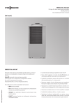
Download Bollettino Tecnico Technical Guide
Transcript
IPE smart
INTERPROIND: refrigeratori di processo
INTERPROIND: process cooling liquid chillers
Company
with Quality System
Certified by DNV
ISO9001/2000
Micro2 ÷ 802
REFRIGERATORI DI LIQUIDO
Condensati ad aria
Ventilatori elicoidali
Compressori: Ermetici Rotativi o Scroll e Semiermetici Alternativi
Evaporatore “NO FROST”
LIQUID CHILLERS
Bollettino Tecnico
Technical Guide
Air cooled
Axial fans
Hermetic Rotary or Scroll and Semi-Hermetic reciprocating
compressors
“NO FROST” evaporator
Tb_ipesmrt_1.1 Rev. 1 del 20/02/2007
GAMMA / RANGE
Grandezza / Size
Capacità
frigorifera
Cooling capacity
kW
Kcal/h
Grandezza / Size
Capacità
frigorifera
Cooling capacity
kW
Kcal/h
Micro2
Micro4
15
20
31
51
81
101
2,9
5,3
8,1
10,8
15,0
21,5
25,1
30,8
121
37,8
2.520
4.580
6.970
9.300
12.900
18.490
21.590
26.490
32.510
151
201
251
301
351
401
502
602
702
802
44,1
56,2
64,5
79,8
96,9
114,7
129,0
159,7
194,7
229,4
37.950
48.340
55.470
68.630
83.350
98.650
110.940
137.350
167.450
198.000
www.euroklimat.it
Tb_ipesmrt_1.1 Rev. 1 del 20/02/2007
2
IPE smart | Micro2 ÷ 802
IP E / XX 151 smart
LETTURA DEL CODICE / HOW TO READ THE CODE
Nome della serie
Versione
PC
Ventilazione condensatore ad aria
T
Pompa di calore
Tropicalizzata (climi caldi)
E
Ventilatore elicoidale
HE
Alta efficienza (R134a)
C
Ventilatore centrifugo
LT
Bassa temperatura (R404a)
Grandezza costruttiva
CARATTERISTICHE TECNICHE
TECHNICAL SPECIFICATIONS
CARPENTERIA
METAL WORKS
CARPENTERIA in lamiera di acciaio zincata, verniciata a forno con
polveri poliuretaniche e dotato di piedi di appoggio per installazione
fissa (solo per modelli Micro2 e Micro4).
BASAMENTO in lamiera di acciaio zincata, verniciata a forno con
polveri poliuretaniche e dotato di piedi di appoggio per installazione
fissa.
CARPENTERIA INTERNA in lamiera di acciaio zincato.
BACINELLA di raccolta dell’acqua piovana, in caso d’installazione
esterna, completa di scarico convogliabile senza lo smontaggio di
nessun pannello (escluso modelli Micro2 e Micro4).
TELAIO in profilati di alluminio anodizzato, con giunti angolari in lega
di alluminio (escluso modelli Micro2 e Micro4).
PANNELLI in acciaio zincato con pellicola esterna in PVC. Il fissaggio
al telaio di alluminio è realizzato con viti in acciaio inox montate a filo
dei pannelli (escluso modelli Micro2 e Micro4).
GUARNIZIONI di tenuta sulle battute dei pannelli in coestruso plastico
a consistenza differenziata (escluso modelli Micro2 e Micro4).
METAL WORKS in galvanized sheet steel, stove-enamelled with
polyurethane powders and is equipped with bearing foot, for fixed
installation (only for Micro2 and Micro4 models).
BASE FRAME in galvanized sheet steel, stove-enamelled with
polyurethane powders and is equipped with bearing foot, for fixed
installation.
INTERNAL METAL WORKS in galvanized sheet steel.
DRIP TRAY for rain water collection in case of outside installation,
complete with type discharge fitting connectable without
disassembling any panel (Models Micro2 – Micro4 not included).
FRAME is made in anodized aluminium profiles, using aluminiumalloy angle-joints (Models Micro2 – Micro4 not included).
PANELS in galvanized steel, externally coated with PVC film.
Fastening to aluminium frame by stainless steel screws, fitted on
panels’ edge (Models Micro2 – Micro4 not included).
AIR-TIGHT GASKETS on panels’ edges, made in polyurethane with
dual density (Models Micro2 – Micro4 not included).
SEZIONE VENTILANTE
FANS SECTION
VENTILATORE/I ELICOIDALE, direttamente accoppiato a motore
elettrico, a 4 o 6 poli, del tipo a rotore esterno, con speciale tenuta a
labirinto per l’acqua, cuscinetti esenti da manutenzione e protezione
termica incorporata. I ventilatori hanno pale a profilo alare
dinamicamente e staticamente bilanciate e sono dotati di griglia
antinfortunistica sulla mandata dell’aria
AXIAL FAN(S) directly coupled to the electric motor, 4 or 6 poles,
external rotor type, with special labyrinth watertight, bearings free
from servicing and incorporated thermal protection. Fans have blades
with haul profile, dinamically and statically balanced and are equipped
with accident prevention grill on air inlet.
CIRCUITO FRIGORIFERO
REFRIGERANT CIRCUIT
Il circuito frigorifero è interamente realizzato in tubo di rame,
saldobrasato con lega di argento, ed è isolato sul tratto aspirante, per
evitare la formazione di condensa. E’ dotato di dispositivo di sicurezza.
Per i modelli dal 502 al 802, il circuito è doppio e completamente
indipendente.
Essenzialmente è costituito da:
COMPRESSORE ERMETICO “ROTATIVO”, per i modelli Micro2 e
Micro4, montato su supporti antivibranti. Il motore elettrico è
raffreddato dal gas refrigerante in aspirazione ed è protetto da
anomalie di esercizio da termistori annegati negli avvolgimenti.
COMPRESSORE ERMETICO “SCROLL”, per i modelli dal 15 al 201
compreso, valvola di sicurezza tra l’aspirazione e la mandata. Il motore
elettrico è raffreddato dal gas refrigerante in aspirazione ed è protetto
da anomalie di esercizio da termistori annegati negli avvolgimenti per i
modelli fino al 81 compreso e protezione elettronica integrale per i
modelli dal 101 al 201. Sono montati su supporti antivibranti e per i
modelli dal 101 al 201 vengono forniti completi di valvole di
intercettazione, sia in mandata che in aspirazione.
COMPRESSORE SEMIERMETICO, per i modelli dal 251 al 802
compreso, completo di sistema di lubrificazione forzata, resistenza per
il riscaldamento dell’olio a macchina ferma, valvola di intercettazione
sulla mandata del gas (sull’aspirazione nel modello 251). Il motore
elettrico è raffreddato dal gas refrigerante in aspirazione ed è protetto
da anomalie di esercizio da protezione elettronica integrale e termistori
annegati negli avvolgimenti. I compressori sono montati su supporti
antivibranti. Per i modelli dal 301 al 802 vengono forniti con testata
parzializzata, per adeguare la potenza frigorifera, in caso di riduzione
dei fabbisogni termici.
www.euroklimat.it
Tb_ipesmrt_1.1 Rev. 1 del 20/02/2007
Refrigerant circuit is completely made in braze welded copper tube
with silver alloy and is insulated on suction part, to avoid creation of
condensate. It is complete with safety device. For models 502 and
802 the circuit is double and completely independent. It is mainly
composed by:
“ROTATIVE” HERMETIC COMPRESSOR, for models Micro2 and
Micro4, fitted on antivibration mountings. Electrical motor is cooled by
refrigerant suction gas and is protected against working anomalies by
thermistors embedded in windings.
HERMETIC COMPRESSOR ”SCROLL”TYPE for models from 15 to
201 included, safety valve between suction and inlet. Electrical motor
is cooled by refrigerant suction gas and is protected against working
anomalies by thermistors embedded in windings for models up to the
81 included and integral electronic protection for models from 101 to
201.They are fitted on antivibration mountings and, models from 101
to 201, are supplied complete with intercepting valves, both in inlet
and in suction.
SEMI-HERMETIC COMPRESSOR for models from 251 to 802
included, complete with forced lubricated system, oil electrical heater
when unit on standby, isolation valve on gas inlet (on gas outlet in
model 251).
Electrical motor is cooled by refrigerant gas in suction and is
protected against working anomalies by integral electronic protection
and thermistors embedded in windings. Compressors are fitted on
antivibration mountings.
For models from 301 to 802 they are supplied with unloaded head, to
adapt cooling capacity in case of reduction of thermal needs.
3
IPE smart | Micro2 ÷ 802
CONDENSATORE ad aria, costituito da una batteria di scambio
termico, con tubi di rame espansi meccanicamente, dentro un pacco di
alette in alluminio. Posizionato in verticale è completamente separato,
insieme al ventilatore, dal resto dei componenti e protetto da urti
accidentali da una grigliatura, integrata nel pannello.
FILTRO FRIGORIFERO a setaccio molecolare, in grado di trattenere
impurità di origine meccanica e deidratare il circuito da tracce di
umidità.
SPIA PASSAGGIO LIQUIDO per la verifica della carica e del tenore di
umidità del gas, grazie ad un indicatore a viraggio cromatico.
VALVOLA SOLENOIDE sulla linea del liquido per i modelli dal 81 al
802 compreso.
RUBINETTO di intercettazione sulla linea del liquido.
VALVOLA DI ESPANSIONE TERMOSTATICA con equilibratore
barostatico esterno.
EVAPORATORE “NO FROST” ad espansione secca in tubi di rame
direttamente inserito in un serbatoio di accumulo in acciaio,
esternamente rivestito con isolamento termico a cellule chiuse a
barriera di vapore.
PRESSOSTATO DI ALTA PRESSIONE a riarmo automatico.
PRESSOSTATO DI BASSA PRESSIONE a riarmo automatico.
PRESSOSTATO DIFFERENZIALE DELL’OLIO, a riarmo manuale per
modelli con compressore semi-ermetico.
PRESSOSTATO/I di regolazione on/off della pressione di
condensazione.
Air cooled CONDENSER, composed by a thermal exchange battery,
with copper tubes mechanically expanded, into aluminium fins
coil.Vertically fitted, together with fan it is completely separated from
the remaining components and is protected against incidental shocks,
thanks to a grill integrated with panel.
REFRIGERANT FILTER with mechanical and dehydrating action, of
molecular-sieve type.
LIQUID SIGHT-GLASS with colour-change indicator for checking gas
charge and humidity.
SOLENOID VALVE on liquid line for all units from 81 to 802 included.
ROTALOCK VALVE on the liquid line.
THERMOSTATIC EXPANSION VALVE with external equalizer.
“NO FROST” EVAPORATOR, dry expansion type with copper tube
nest; internally assembled into steel storage water tank externally
insulated with vapour-proof closed cell thermal insulation.
HIGH-PRESSURE SWITCH with automatic reset.
LOW-PRESSURE SWITCH with automatic reset.
OIL PRESSURE DIFFERENTIAL SWITCH, with manual reset, for
models with semi.-hermetic compressor.
PRESSURE SWITCH/ES on/off, for condensing pressure control.
CIRCUITO IDRICO
WATER CIRCUIT
ELETTROPOMPA centrifuga per la circolazione dell’acqua completa
di motore elettrico a 2 poli direttamente accoppiato.
MANOMETRO sulla mandata acqua della pompa, per il controllo della
corretta pressione del circuito.
VALVOLA DI BY-PASS manuale per mantenere, entro valori corretti,
le prestazioni della pompa adeguandole alle caratteristiche
dell’impianto.
La valvola è posizionata all’esterno dell’unità per consentirne la
manovra senza lo smontaggio di nessun pannello.
PRESSOSTATO DIFFERENZIALE sul circuito acqua.
VALVOLA DI SFOGO ARIA con portagomma ed apertura rapida.
La valvola è posizionata all’esterno dell’unità per consentirne la
manovra senza lo smontaggio di nessun pannello.
VALVOLA DI SCARICO ACQUA con portagomma ed apertura rapida.
La valvola è posizionata all’esterno dell’unità per consentirne la
manovra senza lo smontaggio di nessun pannello.
VALVOLA DI SICUREZZA lato circuito acqua.
CENTRIFUGAL PUMP for water circulation, complete with 2 poles
electric motor, directly coupled.
GAUGE on pump’s water outlet, for the control of the correct circuit
pressure.
BY-PASS VALVE, manual type, to keep pump’s performance within
correct values, adapting them to plant’s characteristics.The valve is
placed outside the unit for handling without disassembling any panel.
DIFFERENTIAL PRESSURE SWITCH on water circuit.
AIR VENTING VALVE, equipped with rubber holder and of quick
open type. The valve is placed outside the unit for fitting without
disassembling any panel.
WATER DISCHARGE VALVE, equipped with rubber holder and of
quick open type.The valve is placed outside the unit for fitting without
disassembling any panel.
SAFETY VALVE on water circuit.
QUADRO DI CONTROLLO
CONTROL PANEL
Ogni unità è corredata di quadro elettrico, costruito e cablato secondo
le norme CEI-EN applicabili, ed è completo di:
Sezionatore generale con funzione di blocco porta.
Protezioni su ogni utenza.
Teleruttore motore del compressore.
Teleruttori dei motori dei ventilatori.
Teleruttore motore pompa.
Trasformatore per i servizi ausiliari.
CONTROLLO A MICROPROCESSORE con le seguenti funzioni:
Regolazione di temperatura dell’acqua refrigerata tramite
inserzione del/i compressore/i (regolazione ON/OFF) o
attivazione del controllo di capacità per i modelli dal 251 al
802 compreso.
Contaore di funzionamento del/i compressore/i.
Temporizzazione di avviamento del/i compressore/i e
controllo della limitazione del numero degli spunti.
Rotazione degli avviamenti dei compressori, per i modelli dal
502 al 802, con equalizzazione delle ore di funzionamento.
Protezione antigelo.
Interfaccia con l’operatore a display digitale.
Predisposizione per uscita seriale (opzionale).
Gestione allarme cumulativo remotabile con contatto pulito.
Predisposizione per ON/OFF a distanza
Allarmi codificati dei componenti principali
Ripristino allarmi e sblocco macchina da tastiera
Allarme acustico.
Tastiera di comando.
Interruttore on/off di sicurezza.
Funzioni di autodiagnosi.
Every unit is equipped with electric panel, produced and wired as per
applicable
IEC-EN norms and is complete with:
Main switch and door-lock.
Protection on every electrical load.
Compressor motor contactor.
Fan motor contactors.
Pump motor contactor.
Auxiliary transformer.
MICROPROCESSOR CONTROL with the following functions:
Chilled-water temperature control thanks to compressor/s ON /
OFF regulation system or activation of capacity step for models
from 251 to 802 included.
Compressor working-time meter.
Compressor-start timing and control of inrush number limitation.
Rotation of compressors’ start-up for models from 502 up to
802, with equalization of working hours.
Anti-freeze protection.
Digital display operator interface.
Connection for serial output ( optional ).
Alarms management with free contacts for cumulative alarms
Connection for remote ON/OFF
Codified Alarms of the main components
Alarms reset and unit set-up from keyboard.
Alarm buzzer.
Control keyboard.
On/off safety switch.
Auto-diagnostic functions.
CONDIZIONI DI FORNITURA
SALES CONDITIONS
PROVE E COLLAUDI IN FABBRICA.
CARICA DI REFRIGERANTE R407c ED OLIO incongelabile.
MANUALE USO E MANUTENZIONE - CERTIFICATO DI CONFORMITÀ
www.euroklimat.it
Tb_ipesmrt_1.1 Rev. 1 del 20/02/2007
FACTORY TESTS AND INSPECTION.
REFRIGERANT (R407c) AND OIL CHARGE (antifreeze oil type).
USE & INSTRUCTIONS MANUAL – COMPLIANCE DICLARATION.
4
IPE smart | Micro2 ÷ 802
VARIANTI COSTRUTTIVE
MANUFACTURING VARIATIONS
ST: versione STANDARD.
ST: STANDARD version.
T: versione TROPICALIZZATA. Studiata e realizzata per installazioni
in luoghi ove la temperatura ambiente supera i 40°C.
T: TROPICAL version. Designed for installations where
environment temperatures exceeds 40°C.
PC: versione a POMPA di CALORE.
PC: HEAT PUMP version.
ALIMENTAZIONE ELETTRICA a tensione e/o frequenza diversa da
quella standard.
ELECTRICAL SUPPLY at voltage and/or frequencies different
from the standard.
APPLICAZIONI TIPICHE
TYPICAL APPLICATIONS
PRESSE INIEZIONE-SOFFIAGGIO
Injection and Blow Moulding machines
IMPIANTI ESTRUSIONE - TERMOFORMATURA
Extrusion lines – Thermoforming Lines
RETTIFICHE
Grinding Machines
CENTRI DI LAVORO
Maching centers
UNITA’ TRATTAMENTO ARIA-CONDIZIONAMENTO
Air handling Units – Air conditioning
IMPIANTI CHIMICI-FARMACEUTICI-ALIMENTARI
Chimical-pharmaceutical and food plants
IMPIANTI STAMPA ROTOCALCO-FLEXO
Rotogravure-Flexo printing plants
www.euroklimat.it
Tb_ipesmrt_1.1 Rev. 1 del 20/02/2007
5
IPE smart | Micro2 ÷ 802
ACCESSORI
OPTIONALS
MANOMETRI di alta e bassa pressione del refrigerante a
bagno di glicerina e manometro olio per i mod. dal modello
251 al modello 802 compreso.
Code
MAN-HLO
GAUGES for refrigerant low and high pressures, embedded
in glycerine and oil gauge for models from size 251 to size
802.
Code:
PAN-PAL
PANNELLI IN PERALLUMAN. ALUMINIUM PANELS panelling in aluminium alloy.
Code:
PAN-INX
PANNELLI IN ACCIAIO INOX. STAINLESS STEEL PANELS.
Code:
PMP-5BR
ELETTROPOMPA CENTRIFUGA con prevalenza maggiorata a 5 bar. CENTRIFUGAL ELECTROPUMP with increased pressure 5 bar.
Code:
SCD-485
SCHEDA DI COMUNICAZIONE RS 485
CAREL, ModBus).
(protocollo
SERIAL OUTPUT RS 485 (comunication protocol CAREL,
ModBus).
TERMINALE REMOTO per controllo a distanza.
Code:
TRM-MC2
Code:
MC2-ADV
REMOTE TERMINAL for remote control.
FUNZIONI AVANZATE STRUMENTO DI CONTROLLO (attivazione automatica pompa per sicurezza antigelo, alta temperatura
impianto, ecc.).
ADVANCED FUNCTIONS OF THERMOREGULATOR (automatic activation of the pump for antifreezing, over-temperature, etc.).
Code:
KIT-VSA
Code:
KIT-VSC
Code:
RMP-AUT
Code:
SCD-485
KIT VASO APERTO per il funzionamento delle unità in circuito aperto.
KIT OPEN EXPANSION TANK for unit’s working with open water circuit.
KIT VASO CHIUSO per il funzionamento delle unità in circuito chiuso.
KIT CLOSED EXPANSION TANK for unit’s working with closed water circuit.
KIT RIEMPIMENTO ACQUA AUTOMATICO
KIT FOR AUTOMATIC WATER FILLING
VALVOLA DI SOVRAPRESSIONE / BY-PASS AUTOMATICO della
portata dell’acqua.
WATER OVER PRESSURE BY-PASS.
Code:
TNM-VDV
Code:
CON-MOD
Code:
RUO-GIR
Code:
PMP-DUO
TENUTA MECCANICA SPECIALE per impieghi in bassa temperatura o per fluidi di processo.
SPECIAL MECHANICAL SEAL for low liquid temperatureapplications or for process fluids.
CONTROLLO di CONDENSAZIONE modulante dal modello 31 al modello 802.
MODULATING FAN SPEED CONTROL from 31 to 802.
RUOTE PIROETTANTI (solo per modelli da MICRO2 a IPE151). ROLLING WHEELS (only from MICRO2 to IPE151 models).
DOPPIA POMPA (STAND-BY) – solo per modelli dal 301 al 802.
DOUBLE PUMP (STAND-BY) – Only for models from 301 to 802.
www.euroklimat.it
Tb_ipesmrt_1.1 Rev. 1 del 20/02/2007
6
IPE smart | Micro2 ÷ 802
DATI TECNICI / TECHNICAL DATA
Micro 2 ÷ 201
Modelli IPE smart
Potenza frigorifera(1)
Cooling capacity(1)
kW
Kcal/h
Potenza imp. compr.(1)
Compress. power input(1)
kW
COP
Micro 2
Micro 4
15
20
31
51
81
101
121
151
2,9
5,3
8,1
10,8
15,0
21,5
25,1
30,8
37,8
44,1
201
56,2
2.520
4.580
6.970
9.300
12.900
18.490
21.590
26.490
32.510
37.950
48.340
0,7
1,4
1,7
2,5
3,5
4,8
5,4
6,6
8,5
10,2
11,3
4,1
3,8
4,8
4,3
4,3
4,5
4,6
4,7
4,4
4,3
5,0
76
76
79
80
77
77
81
81
81
81
82
(3)
Potenza sonora
Sound power level(3)
dB(A)
Alimentazione elettrica
Power supply
230V/1~/50Hz + T
400V-415V/3~/50Hz + T
Compressori / Compressors
Quantità / Quantity
n°
Tipologia / Type
-
1
Rotativo / Rotary
SCROLL
Ventilatori / Fans
Portata aria totale
Total air flow
m3/h
Numero e potenza motori
Motor quantity and power
Velocità di rotazione
Fan speed
1.890
1.890
2.630
3.600
5.040
5.400
9.360
9.360
11.520
11.520
17.640
kW
0,07
0,07
0,12
0,20
0,32
0,42
0,69
0,69
0,98
0,98
0,69
rpm
1.390
1.390
1.380
940
910
930
930
930
930
930
930
23
23
27
27
65
65
160
160
160
160
290
m3/h
0,5
0,9
1,6
1,9
2,6
3,7
4,3
5,2
6,5
7,6
9,7
kW
0,33
0,33
0,37
0,60
0,60
0,60
0,90
1,5
1,5
1,5
1,5
bar
3,7
3,2
2,9
2,8
3,1
2,7
2,6
3,0
3,0
2,9
2,8
0,2
0,4
0,5
0,7
1,1
1,3
2,2
2,2
3,0
3,0
3,6
n°
1
2
Evaporatore / Evaporator
Contenuto acqua
Water content
lt
Pompa acqua / Water pump
Portata acqua nom.(1)
Nominal water flow(1)
Potenza nominale
Nominal power
(1)
Pressione acqua nom.
Nominal head pressure(1)
Portata acqua
Water flow
min
max
0,6
1,1
1,7
2,0
2,9
4,2
5,4
6,6
7,7
9,2
11,1
Prevalenza utile
Useful head
min
3,6
3,0
2,1
2,3
2,7
1,6
2,6
3,0
2,9
2,8
2,6
4,0
4,0
3,8
4,2
4,0
3,8
3,0
3,1
3,1
3,1
3,1
m3/h
bar
max
Circuito frigorifero / Refrigerating circuit
Refrigerante / Refrigerant
Carica refrigerante
Refrigerant charge
R407c
Kg
0,7
0,8
1,5
1,6
2,4
2,8
5,0
5,5
6,0
6,5
8,5
Lunghezza / Length
mm
740
740
830
830
980
980
1.280
1.280
1.280
1.280
1.930
Profondità / Depth
mm
550
550
650
650
800
800
990
990
990
990
990
Altezza / Height
mm
885
885
1.320
1.320
1.785
1.785
2.055
2.055
2.075
2.075
2.155
Peso di spedizione
Shipping weigth
Kg
85
95
170
190
280
300
520
550
560
575
760
Peso in funzionamento
Operating weigth
Kg
108
118
200
220
350
370
680
710
720
740
1.050
Micro 2
Micro 4
15
20
31
51
81
101
121
151
201
Dimensioni / Dimensions
Pesi / Weights
(1)
(1)
(2)
(2)
Prestazioni riferite alle seguenti condizioni: Temp. di ingresso fluido = 20°C / Temp. di uscita fluido = 15°C / Fluido = acqua / Temp. aria entrata al condensatore = 25°C
Capacities referred to: Fluid inlet temp. = 20°C / Fluid outlet temp. = 15°C / Fluid = water / Air temperature on condenser = 25°C
Livelli di potenza sonora medi nominali LW [dB(A) rif. I picowatt] – Indeterminazione sui livelli ponderati (A) : ISO 2204 grado 3 survey.
Average nominal sound power level LW [dB(A) rif. I picowatt] - Imprecision on ponderate level (A) : ISO 2204 grade 3 survey
www.euroklimat.it
Tb_ipesmrt_1.1 Rev. 1 del 20/02/2007
7
IPE smart | Micro2 ÷ 802
DATI TECNICI / TECHNICAL DATA
Modelli IPE smart
Potenza frigorifera
Cooling capacity (1)
(1)
kW
Kcal/h
Potenza impegnata (1)
Cooling capacity (1)
kW
COP
251 ÷ 802
251
301
351
401
502
602
702
802
64,5
79,8
96,9
114,7
129,0
159,7
194,7
229,4
55.470
68.630
83.350
98.650
110.940
137.350
167.450
198.000
14,1
18,6
23,2
26,1
28,2
37,2
46,4
52,2
4,6
4,3
4,2
4,4
4,6
4,3
4,2
4,4
84
85
86
86
87
88
88
89
52.600
72.000
(3)
Potenza sonora
Sound power level (3)
Alimentazione elettrica
Power supply
dB(A)
400V-415V/3~/50Hz
Compressori / Compressors
Quantità / Quantity
n°
Tipologia / Type
-
1
2
Semiermetico a pistoni / Semi-hermetic reciprocating
Ventilatori / Fans
Portata aria totale
Total air flow
m3/h
Numero e potenza motori
Motor quantity and power
Velocità di rotazione
Fan speed
17.280
26.280
27.720
27.720
34.920
3
39.960
n°
2
4
6
kW
0,69
0,69
0,98
0,98
0,69
0,98
0,69
0,98
rpm
930
930
930
930
930
930
930
930
lt
290
460
460
460
480
480
920
920
m3/h
11,1
13,7
16,7
19,7
22,2
27,8
33,5
39,6
kW
1,8
1,8
2,2
2,2
3,0
3,0
4,0
4,0
bar
3,2
3,0
2,9
2,8
2,7
2,7
2,5
2,4
7,2
7,2
9,0
11,3
12,5
15,6
24,0
28,5
48,0
Evaporatore / Evaporator
Contenuto acqua
Water content
Pompa acqua / Water pump
Portata acqua nominale (1)
Nominal water flow (1)
Potenza nominale
Nominal power
Pressione acqua nom.(1)
Nominal head pressure(1)
Portata acqua
Water flow
min
max
13,3
15,6
19,6
23,6
27,5
33,3
39,0
Prevalenza utile
Useful head
min
3,0
2,8
2,8
2,7
2,3
2,1
3,3
3,2
3,5
3,5
3,3
3,2
2,9
2,8
3,0
2,8
m3/h
bar
max
Circuito frigorifero / Refrigerating circuit
Refrigerante / Refrigerant
Carica refrigerante R407c
R407c refrigerant charge
R407c
Kg
9,5
11,5
12,5
13,5
19,0
23,0
26,0
27,5
Lunghezza / Length
mm
1.930
2.580
2.580
2.580
3.520
3.520
3.900
3.900
Profondità / Depth
mm
990
990
990
990
990
990
2.000
2.000
Altezza / Height
mm
2.155
2.155
2.175
2.175
2.215
2.215
1.835
1.835
Peso di spedizione
Shipping weigth
Kg
860
1.010
1.100
1.120
1.600
1.720
1.800
1.880
Peso in funzionamento
Operating weigth
Kg
1.150
1.300
1.560
1.580
2.080
2.200
2.720
2.800
251
301
351
401
502
602
702
802
Dimensioni / Dimensions
Pesi / Weights
(1)
(1)
(2)
(2)
Prestazioni riferite alle seguenti condizioni: Temp. di ingresso fluido = 20°C / Temp. di uscita fluido = 15°C / Fluido = acqua / Temp. aria entrata al condensatore = 25°C
Capacities referred to: Fluid inlet temp. = 20°C / Fluid outlet temp. = 15°C / Fluid = water / Air temperature on condenser = 25°C
Livelli di potenza sonora medi nominali LW [dB(A) rif. I picowatt] – Indeterminazione sui livelli ponderati (A) : ISO 2204 grado 3 survey.
Average nominal sound power level LW [dB(A) rif. I picowatt] - Imprecision on ponderate level (A) : ISO 2204 grade 3 survey
www.euroklimat.it
Tb_ipesmrt_1.1 Rev. 1 del 20/02/2007
8
IPE smart | Micro2 ÷ 802
LIMITI DI FUNZIONAMENTO / OPERATING RANGE
Min.
Temperatura ambiente
Ambient temperature
Max.
0°C (standard)
0°C (standard)
Min.
-15°C (fan control)
-20°C (low temp.)
Temperatura fluido di uscita
Fluid outlet temperature
+43°C (standard)
+15°C (standard)
Max.
+48°C (tropical)
FATTORI DI CONVERSIONE PER FUNZIONAMENTO CON MISCELE ACQUA-GLICOLE
WATER-GLYCOL SOLUTION OPERATING FACTORS
Temperatura di congelamento / Freezing temperature
Glicole etilenico in peso / Ethylene glycol by weight
0°C
-5°C
-10°C
-15°C
-20°C
-25°C
0
12%
20%
28%
35%
40%
Fattore correttivo potenza frigorifera / Cooling capacity correction factor
cPf
1
0,985
0,98
0,974
0,97
0,965
Fattore correttivo portata / Water flow correction factor
cQ
1
1,02
1,04
1,075
1,11
1,14
Fattore correttivo perdita di carico
cdp
1
1,07
1,11
1,18
1,22
1,24
FATTORI DI CONVERSIONE POTENZA FRIGORIFERA
COOLING CAPACITY CORRECTION FACTOR
25°C
30°C
35°C
40°C
-20°C
Versione LT (Bassa temp.)
LT version (Low temp.)
K
-5°C
0°C
+5°C
+7°C
+10°C
+12°C
+15°C
0,49
0,64
0,74
0,78
0,86
0,90
1,00
0,44
0,55
0,70
0,74
0,81
0,88
0,94
0,41
0,51
0,65
0,69
0,76
0,82
0,89
0,47
0,60
0,64
0,71
0,76
0,82
Versione T (tropicalizzata)
T version (hot clima)
45°C
CON OPZIONE CONTROLLO di CONDENSAZIONE modulante (disp. per modelli 31 ÷ 802)
WITH OPTION MODULATING FAN SPEED CONTROL (availabble for 31 ÷ 802 models)
La potenza frigorifera in condizioni diverse da quelle nominali si ottengono
moltiplicando il valore nominale riportato nella tabella “Dati tecnici” per il
rispettivo coefficiente correttivo “K”.
The cooling capacity in other conditions than nominal are obtained by
multiplying the nominal values shown at “Technical data” by the respective
correction factor “K”.
Esempio di calcolo / Example
IPE 301
(1)
Potenza frigorifera nominale
(1)
Nominal cooling capacity
79,8 kW
Temperatura uscita acqua desiderata / Outlet water temperature request
Temperatura ambiente / Ambient temperature
K
IPE 301
factor a queste condizioni / at these conditions
(1)
Potenza frigorifera nominale
(1)
Nominal cooling capacity
www.euroklimat.it
12°C
35°C
0,82
79,8 x 0,82 = 65,4 kW (12°C / 35°C)
Tb_ipesmrt_1.1 Rev. 1 del 20/02/2007
9
IPE smart | Micro2 ÷ 802
DIMENSIONI RACCORDI IDRAULICI / WATER FITTINGS DIMENSION
IPE smart
Scarico acqua
Water discharge
Scarico aria
Air venting
M2 – M4
15 – 20
Uscita acqua
Water outlet
Ingresso acqua
Water inlet
½”
½”
Scarico condensa
Drain discharge
19 mm
31 – 51
1”
1”
1”¼
1”¼
1”½
1”½
301 ÷ 401
2”
2”
502 – 602
3”
3”
702 – 802
4”
4”
81 ÷ 151
13 mm
201 – 251
13 mm
28 mm
DATI ELETTRICI / ELECTRICAL DATA
IPE
MOTORE COMPRESSORE
MOTORE VENTILAT.
MOTORE POMPA
DATI COMPLESSIVI
SEZION.
COMPRESSOR MOTOR
FAN MOTOR
PUMP MOTOR
TOTAL DATA
SWITCH
P.max
[kW]
smart
n°
P.max
[kW]
M2
1
1,1
M4
1
1,7
15
1
2,9
20
1
31
1
51
1
7,6
81
1
8,0
101
1
10,0
121
1
12,1
151
1
201
1
251
1
19,7
301
1
23,6
351
1
28,9
401
1
37,9
502
2
602
2
702
2
802
2
I. Max
[A]
LRA
[A]
n°
P.max
[kW]
I. Max
[A]
I. Max
[A]
P.max
[kW]
I. Max
[A]
Max LRA
[A]
4,3
19,0
1
0,1
0,44
0,33
2,5
1,5
7,2
22
3 x 16
7,7
34,0
1
0,1
0,44
0,33
2,5
2,1
10,6
31
3 x 16
5,1
32,0
1
0,1
0,3
0,4
1
3,3
6,4
33
3 x 16
3,8
6,6
39,0
1
0,2
0,5
0,6
2,1
4,6
9,2
42
3 x 16
5,1
8,8
45,0
1
0,3
0,7
0,6
1,5
6,0
11,0
47
3 x 16
12,8
69,0
1
0,4
0,8
0,6
1,5
8,6
15,1
71
3 x 25
15,0
91,0
1
0,7
1,3
0,9
3
9,5
19,3
89
3 x 25
16,5
87,0
1
0,7
1,3
1,5
4
12,2
21,8
92
3 x 32
20,0
102,0
1
1,0
1,8
1,5
4
14,6
25,8
101
3 x 45
15,0
24,5
102,0
1
1,0
1,8
1,5
4
17,5
30,3
108
3 x 45
18,5
32,0
198,0
2
0,7
1,3
1,5
4
21,4
38,5
140
3 x 45
37,0
146,6
2
0,7
1,3
1,8
4,8
22,9
44,3
154
3 x 63
45,0
172,0
3
0,7
1,3
1,8
4,8
27,5
53,6
181
3 x 63
53,0
185,0
3
1,0
1,8
2,2
5
34,1
63,3
195
3 x 80
61,0
225,0
3
1,0
1,8
2,2
5
43,0
71,3
235
3 x 125
19,7
37,0
146,6
4
0,7
1,3
3,0
6,6
45,2
85,6
195
3 x 125
23,6
45,0
172,0
4
1,0
1,8
3,0
6,6
54,1
103,6
230
3 x 125
28,9
53,0
185,0
6
1,0
1,8
4,0
9,8
67,7
126,3
258
3 x 160
37,9
61,0
225,0
6
1,0
1,8
4,0
9,8
85,7
142,3
306
3 x 200
[A]
DATI ELETTRICI POMPE ACQUA A 5bar
ELECTRICAL DATA WATER PUMP (5bar)
IPE smart
P.max
[kW]
I. Max
[A]
15
0,75
2,4
20
1,1
3,6
31 ÷ 51
0,75
2,4
81 ÷ 151
2,2
5,0
201 - 251
3,0
6,6
301 ÷ 401
4,0
9,8
502 - 602
5,5
11,5
702 - 802
7,5
15,5
www.euroklimat.it
Tb_ipesmrt_1.1 Rev. 1 del 20/02/2007
Potenza massima assorbita
P.max [kW]
Maximum power input
Corrente massima assorbita
I. Max [A]
Maximum current input
Corrente a rotore bloccato
LRA
Blocked rotor current
10
IPE smart | Micro2 ÷ 802
SCHEMA CIRCUITO FRIGORIFERO - IDRAULICO / GAS – WATER CIRCUIT DIAGRAM
Micro 2 – Micro 4
IPE 15 ÷ IPE 401
www.euroklimat.it
Tb_ipesmrt_1.1 Rev. 1 del 20/02/2007
11
IPE smart | Micro2 ÷ 802
SCHEMA CIRCUITO FRIGORIFERO - IDRAULICO / GAS - WATER CIRCUIT DIAGRAM
IPE 502 - 602
Legenda
1
2
3
4
5
6
7
8
9
10
11
12
Compressore
Evaporatore
Condensatore ad aria
Ventilatore condensatore
Vasca di accumulo in pressione
Pompa acqua
Valvola d’espansione
Termoregolatore elettronico
Valvola solenoide liquido
Filtro meccanico disidratatore
Valvola di sicurezza di scarico
(1)
Manometro di bassa pressione
Compressor
Evaporator
Air condenser
Condenser fan
Pressurized water tank
Water pump
Expansion valve
Electronic termoregulator
Liquid solenoid valve
Mechanical dehydrating filter
Safety discharge valve
(1)
Low pressure gauge
13
14
15
16
17
18
19
20
21
22
23
24
(1)
Manometro di alta pressione
(2)
Manometro olio
Pressostato di bassa pressione
Pressostato di alta pressione
(3)
Pressostato differenziale olio
Pressostato controllo ventola
Manometro pressione idrica
(4)
Valvola di sicur. lato acqua
(4)
Pressostato diff. acqua
(1)
Vaso d’espansione
(1)
Vaso espansione chiuso
(1)
Caricamento automatico
(1)
High pressure gauge
(2)
Oil pressure switch
Low pressure switch
High pressure switch
(3)
Oil diff. pressure switch
Fan pressure switch
Hydraulic pressure gauge
(4)
Water safety dischrge valve
(4)
Differential pressure switch
(1)
Expansion tank
(1)
Closed expansion tank
(1)
Automatic filling
Note:
(1)
(2)
(3)
(4)
Opzione a richiesta per tutti i modelli / Optional for all models
Opzione a richiesta (solo per modelli IPE 251 ÷ 802) / Optional (only for IPE 251 ÷ 802 models)
Solo per modelli IPE 251 ÷ 802 / Only for IPE 251÷ 802 models
Opzione a richiesta per modelli MICRO 2 – MICRO 4 / Optional for MICRO 2 – MICRO 4 models
www.euroklimat.it
Tb_ipesmrt_1.1 Rev. 1 del 20/02/2007
12
IPE smart | Micro2 ÷ 802
SCHEMA CIRCUITO FRIGORIFERO - IDRAULICO / GAS – WATER CIRCUIT DIAGRAM
IPE 702 - 802
Legenda
1
2
3
4
5
6
7
8
9
10
11
12
Compressore
Evaporatore
Condensatore ad aria
Ventilatore condensatore
Vasca di accumulo in pressione
Pompa acqua
Sistema d’espansione
Termoregolatore elettronico
Valvola solenoide liquido
Filtro meccanico disidratatore
Valvola di sicurezza di scarico
(1)
Manometro di bassa pressione
Compressor
Evaporator
Air condenser
Condenser fan
Pressurized water tank
Water pump
Expansion system
Electronic termoregulator
Liquid solenoid valve
Mechanical dehydrating filter
Safety discharge valve
(1)
Low pressure gauge
13
14
15
16
17
18
19
20
21
22
23
24
(1)
Manometro di alta pressione
(2)
Manometro olio
Pressostato di bassa pressione
Pressostato di alta pressione
(3)
Pressostato differenziale olio
Pressostato controllo ventola
Manometro pressione idrica
(4)
Valvola di sicur. lato acqua
(4)
Pressostato diff. acqua
(1)
Vaso d’espansione
(1)
Vaso espansione chiuso
(1)
Caricamento automatico
(1)
High pressure gauge
(2)
Oil pressure switch
Low pressure switch
High pressure switch
(3)
Oil diff. pressure switch
Fan pressure switch
Hydraulic pressure gauge
(4)
Water safety dischrge valve
(4)
Differential pressure switch
(1)
Expansion tank
(1)
Closed expansion tank
(1)
Automatic filling
Note:
(1)
(2)
(3)
(4)
Opzione a richiesta per tutti i modelli / Optional for all models
Opzione a richiesta (solo per modelli IPE 251 ÷ 802) / Optional (only for IPE 251 ÷ 802 models)
Solo per modelli IPE 251 ÷ 802 / Only for IPE 251÷ 802 models
Opzione a richiesta per modelli MICRO 2 – MICRO 4 / Optional for MICRO 2 – MICRO 4 models
www.euroklimat.it
Tb_ipesmrt_1.1 Rev. 1 del 20/02/2007
13
IPE smart | Micro2 ÷ 802
POSSIBILI CONFIGURAZIONI / AVAILABLE CONFIGURATIONS
COMPRESSORE/I ERMETICO/I
Hermetic compressor/s
COMPRESSORE/I SEMI-ERMETICO
Semi-hermetic compressor/s
CONDENSAZIONE AD ARIA
Air condensing
CONDENSAZIONE AD ACQUA
Water condensing
VENT. ASSIALE
Axial fan
VENT. CENTRIFUGO
Radial fan
VASO APERTO
Open vessel
VASO CHIUSO
Closed vessel
POMPA ACQUA
Water pump
EVAPORATORE + SERBATOIO
Evaporator + Tank
VALVOLA SOVRAPRESS. BY-PASS
Over-press. by-pass valve
DOPPIA POMPA ACQUA
(STAND-BY)
Twin water pump
VALVOLA MODULANTE
Modulating valve
DOPPIA POMPA ACQUA
Twin water pump
EVAPORATORE A FASCIO TUB.
Shell & tube evaporator
VALVOLA SOVRAPRESS. BY-PASS
Over-press. by-pass valve
POMPA ACQUA riciclo
Water pump (circulating)
DOPPIA POMPA ACQUA
(STAND-BY)
Twin water pump
SERBATOIO ACQUA
Water tank
EVAPORATORE A PIASTRE
Brazed-plate heat exchanger
DOPPIA POMPA ACQUA riciclo
(STAND-BY)
Twin water pump (circulating)
VALVOLA MODULANTE
Modulating valve
DOPPIA POMPA ACQUA
Twin water pump
www.euroklimat.it
Tb_ipesmrt_1.1 Rev. 1 del 20/02/2007
14
IPE smart | Micro2 ÷ 802
DISEGNO DIMENSIONALE / DIMENSIONAL DRAWING
www.euroklimat.it
Tb_ipesmrt_1.1 Rev. 1 del 20/02/2007
Micro 2 – Micro 4
15
IPE smart | Micro2 ÷ 802
DISEGNO DIMENSIONALE / DIMENSIONAL DRAWING
www.euroklimat.it
Tb_ipesmrt_1.1 Rev. 1 del 20/02/2007
IPE 15 ÷ IPE 51
16
IPE smart | Micro2 ÷ 802
DISEGNO DIMENSIONALE / DIMENSIONAL DRAWING
www.euroklimat.it
Tb_ipesmrt_1.1 Rev. 1 del 20/02/2007
IPE 81 ÷ IPE 151
17
IPE smart | Micro2 ÷ 802
DISEGNO DIMENSIONALE / DIMENSIONAL DRAWING
www.euroklimat.it
Tb_ipesmrt_1.1 Rev. 1 del 20/02/2007
IPE 201 ÷ IPE 251
18
IPE smart | Micro2 ÷ 802
DISEGNO DIMENSIONALE / DIMENSIONAL DRAWING
www.euroklimat.it
Tb_ipesmrt_1.1 Rev. 1 del 20/02/2007
IPE 301 ÷ IPE 401
19
IPE smart | Micro2 ÷ 802
DISEGNO DIMENSIONALE / DIMENSIONAL DRAWING
www.euroklimat.it
Tb_ipesmrt_1.1 Rev. 1 del 20/02/2007
IPE 502 ÷ IPE 602
20
IPE smart | Micro2 ÷ 802
DISEGNO DIMENSIONALE / DIMENSIONAL DRAWING
www.euroklimat.it
Tb_ipesmrt_1.1 Rev. 1 del 20/02/2007
IPE 702 - 802
21
IPE smart | Micro2 ÷ 802
Note
www.euroklimat.it
Tb_ipesmrt_1.1 Rev. 1 del 20/02/2007
22
IPE smart | Micro2 ÷ 802
tb_ipesmart_1.1 [Ver. 1.1 Rev.1 del 20-02-2007]
Euroklimat S.p.A.
Via Liguria, 8 – 27010 SIZIANO (PV) ITALY
Tel. (+39) 0382.610282 – Fax (+39) 0382.617782
www.euroklimat.it - Email: [email protected]
L’Azienda è costantemente impegnata in un continuo miglioramento tecnico e produttivo, pertanto i dati contenuti all’interno del presente manuale possono essere soggetti a variazioni senza obbligo di preavviso.
All technical specifications presented in this manual are not binding and subject to change without notice.


