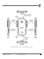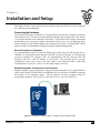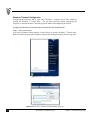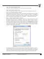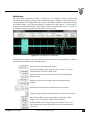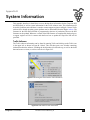
1
User Manual Salt Lake City, UT, USA Document Version R01550_08 This document was, as far as possible, accurate at the time of release. However, subsequent changes may have been made to the software and hardware. Ripple reserves the right to alter specifications and details as required. Late-breaking information may be supplied separately for completeness. Trademarks of Ripple ripple and grapevine are registered trademarks of Ripple. The names of specific devices, such as Grapevine NIP, are trademarks of Ripple. Trellis and Scout are trademarks of Ripple. Other Trademarks Bi-Lobe is a registered trademark of Omnetics Connector Corporation. Apple, Mac, Macintosh, and OS X are registered trademarks of Apple Computer, Inc. Windows and Windows 7 are either registered trademarks or trademarks of Microsoft Corporation. Linux is a registered trademark of Linus Torvalds. LEMO is a registered trademark of LEMO USA, Inc. MATLAB is a registered trademark of The MathWorks, Inc. Intel is a registered trademark of Intel Corporation. NETGEAR is a registered trademark of NETGEAR, Inc. All other trademarks are the property of their respective owners. Product: Grapevine Neural Interface System For use with Trellis software suite version 1.6.1 Copyright © December 2015 Ripple, LLC 2056 South 1100 East, Salt Lake City, UT 84106, USA All rights reserved. No part of this document may be reproduced by any means without the prior written permission of Ripple. Website: Technical Support: www.rippleneuro.com [email protected] Document Version R01550_08 Human Use Considerations The Grapevine Neural Interface System described herein, with exceptions noted, has been designed for clinical use with humans. The system has been used with humans through Institutional Review Board approval at various universities and institutions. Ripple has tested all components of the Grapevine Neural Interface System for isolation and leakage current per IEC60601-1 standards. Components of the system that are not intended for human use are specifically noted throughout this manual. Standard Symbols in Use IEC 60101-0102 Danger of Electrostatic Discharge (ESD) IEC 60417-5031 Direct Current IEC 60417-5036 Dangerous Voltage IEC 60417-5032 Alternating Current IEC 60417-5335 Type of CF Applied Part IEC 60417-5021 Equipotentiality Connector EN-980 Warning IEC 60417-5008 OFF (power) EN-980 Serial Number IEC 60417-0007 ON (power) Specifications iii Power Requirements 110 VAC at 60 Hz or 240 VAC at 50 Hz, 8 A max load Serviceable Fuses 5 x 20 mm, 250 V, 2 A, Slow Blow (Scout processor only) Compliance Standards EU Directive 2004/108/EC (EMC) and Directive 2006/95/EC (LVD) EN 61326-1:2013 (EMC), EN 55011 (EMC), EN 61010-1:2010 (LVD) Type of Protection Class II Degree of Protection Type CF Applied Part Mode of Operation Continuous Water Ingress Protection Ordinary Equipment, not fluid resistant, IP20 Operating Environment 10 ºC to 40 ºC, 5 to 95% R.H. (non-condensing) Storage Environment -20 ºC to 50 ºC, 5 to 100% R.H. (non-condensing) Document Version R01550_08 Preface Warnings The Grapevine system should only be used with components provided by Ripple or approved by Ripple engineers. Do not ingest any components of the Grapevine system. Only connect the Grapevine system to properly tested and grounded AC outlets. Do not connect the Grapevine system components to an outlet controlled by a wall switch. Do not use the Grapevine system in the presence of flammable gases. Keep all components of the Grapevine system away from liquids. Contact with water can lead to electric shock. The Grapevine system is not sterile. It may be used in conjunction with sterile devices but should be kept outside sterile environments. The Grapevine system may be used with third-party components approved by Ripple engineers. Follow all manufacturer recommendations for third-party components as improper use can compromise the safety of the Grapevine system components. Electrostatic Discharge Instructions Grapevine system components that are sensitive to electrostatic discharge are marked with the ESD symbol. For these Grapevine components, users should not directly touch any internal pins and should adhere to the following precautions when connecting electrodes or adapters to these components. Users should always ground themselves before handling these Grapevine components. Users should then ground the Grapevine component before connecting to electrodes or adapters by touching the screw terminals of the component cable or by touching the metal shell of the component. Users should ensure that the subject is properly grounded before connecting the Grapevine component to electrodes attached to the subject. Product Cleaning Grapevine components should only be cleaned with lightly-wetted cloths using water or alcohol. Grapevine components should not be immersed in or sprayed with any liquids or gases. Warranty Products provided by Ripple are warrantied to be free from defects in materials and manufacturing for a period of one year from the date of shipment. This warranty is voided by abuse, negligent handling, or misapplication of the product, or modifications to the product by persons not authorized by Ripple. Any product that does not comply with this warranty shall be replaced or repaired at the option of Ripple. Unless addressed in a separate agreement, this constitutes the sole warranty provided by Ripple and there are no other warranties, expressed or implied, which extend beyond those described herein or to anyone other than the original purchaser, including the implied warranties of merchantability and fitness for a particular purpose. In no event shall Ripple be liable for any direct, indirect, incidental or consequential damages, or for the infringement of any patent rights or third-party rights, due to the use of its products or consulting and design services. System Calibration and Diagnostics The Grapevine Neural Interface System goes through a startup routine every time it is powered on to verify that the processor and all Front Ends are working correctly. Ripple recommends that the processor be sent in once a year for a full diagnostic check-up by Ripple engineers. There is no cost for the diagnostic checkup outside of normal shipping costs. Ripple recommends that users keep all original Grapevine packaging for this purpose. Return Merchandise Authorization (RMA) Process Ripple Grapevine products that require maintenance or repair should be returned to the address below only after receiving a Return Merchandise Authorization number from Ripple Support ([email protected] or +1-801-413-0139). Grapevine components should be shipped to Ripple in secure, anti-static, padded packaging. Ripple recommends that users keep all original Grapevine packaging in case of repair or maintenance needs. Ripple 2056 South 1100 East Salt Lake City, UT 84106 USA Grapevine User Manual Document Version R01550_08 iv Contents CHAPTER 1 HARDWARE OVERVIEW ........................................................................................................... 7 How to Use This Manual ............................................................................................................... 7 Grapevine Neural Interface System ......................................................................................... 7 Hardware Requirements ............................................................................................................. 8 Operating System Requirements .............................................................................................. 8 Understanding Grapevine System Components .................................................................. 8 Neural Interface Processor (NIP) .......................................................................................................8 Front End Interface Cables ................................................................................................................ 13 Front Ends................................................................................................................................................. 13 Nano Style FEs ....................................................................................................................................................... 13 Micro Style FEs ...................................................................................................................................................... 13 Surf S ......................................................................................................................................................................... 13 EMG............................................................................................................................................................................ 13 Digital I/O ............................................................................................................................................................... 17 Analog I/O ............................................................................................................................................................... 19 Scout Processor ...................................................................................................................................... 21 CHAPTER 2 INSTALLATION AND SETUP ................................................................................................... 22 Connecting the Hardware ......................................................................................................... 22 Direct Connection to Computer ....................................................................................................... 22 Multiple Computer Connections to the Processor ................................................................... 22 Windows 7 Network Configuration ............................................................................................... 23 Mac OS X Network Configuration .................................................................................................... 25 Linux Network Configuration ........................................................................................................... 26 CHAPTER 3 TRELLIS SOFTWARE SUITE ................................................................................................... 27 Using Trellis Software................................................................................................................ 27 Instruments ................................................................................................................................... 28 Applications................................................................................................................................... 33 Raster .......................................................................................................................................................... 33 Spike Grid .................................................................................................................................................. 35 Heat Map Display ................................................................................................................................................. 36 Electrode Maps ...................................................................................................................................................... 37 Spike Scope ............................................................................................................................................... 38 Impedance Analyzer ............................................................................................................................. 42 Stimulation Controller ......................................................................................................................... 44 File Save .......................................................................................................................................... 51 APPENDIX A TECHNICAL INFORMATION .................................................................................................. 54 Supported Front Ends ................................................................................................................ 54 Nano2, Nano2-HV, Nano2+Stim....................................................................................................... 54 Nano ............................................................................................................................................................ 56 Micro2, Micro2-HV, Micro2+Stim ................................................................................................... 56 Micro, Micro-HV, and Micro+Stim................................................................................................... 57 Surf S ........................................................................................................................................................... 58 EMG.............................................................................................................................................................. 58 Digital I/O.................................................................................................................................................. 59 Analog I/O ................................................................................................................................................. 60 Discontinued Front Ends .......................................................................................................... 61 Surf D .......................................................................................................................................................... 61 v Document Version R01550_08 Contents APPENDIX B SYSTEM INFORMATION ........................................................................................................ 62 Trellis Software ............................................................................................................................ 62 Grapevine Processors and Front Ends ................................................................................. 63 APPENDIX C HARDWARE & SOFTWARE CONFIGURATION ..................................................................... 66 Hardware........................................................................................................................................ 66 Trellis Software Suite ................................................................................................................. 67 Trellis Configuration File.......................................................................................................... 68 APPENDIX D ADDITIONAL SOFTWARE COMPONENTS ............................................................................ 69 MATLAB® ....................................................................................................................................... 69 Open Source MATLAB® ............................................................................................................ 69 Neuroshare ............................................................................................................................................... 69 Wisteria ...................................................................................................................................................... 69 MKsort ........................................................................................................................................................ 69 Python.............................................................................................................................................. 70 C ......................................................................................................................................................... 70 Third-Party Software Compatibility ..................................................................................... 70 Nex Technologies NeuroExplorer® ............................................................................................... 70 Plexon® Offline Sorter™ ..................................................................................................................... 70 APPENDIX E ADAPTERS............................................................................................................................. 71 Samtec-Omnetics ......................................................................................................................... 71 Front End Cable Saver ................................................................................................................ 71 Touchproof .................................................................................................................................... 71 EMU ................................................................................................................................................... 71 Screw-Terminals for Single-Wire Electrodes .................................................................... 72 Electrode Adapter Rod .............................................................................................................. 72 Analog I/O and Digital I/O Breakouts .................................................................................. 72 Recording Front End Testing .................................................................................................. 73 Stimulation Front End Testing................................................................................................ 73 APPENDIX F TROUBLESHOOTING GUIDE ................................................................................................. 74 APPENDIX G REVISION HISTORY .............................................................................................................. 75 Grapevine User Manual Document Version R01550_08 vi Chapter 1 Hardware Overview How to Use This Manual The chapters and appendices in this manual provide an overview of the Grapevine system hardware, technical information on the Grapevine components, instructions on the installation and use of the Trellis software suite, and additional information on system configuration. This document is not intended as a service manual. The specifications and diagrams that are provided in this manual are to assist users in understanding the capabilities of the Grapevine system. Only authorized Ripple employees and representatives are qualified to repair any component of the system. All rights of the warranty for said component are voided if any other party modifies any component without the written consent of Ripple. Grapevine Neural Interface System The Grapevine system is comprised of several components that can be used for the acquisition of electrophysiological and neurophysiological data. At the heart of the system is a Neural Interface Processor, also referred to as the Grapevine NIP. The Grapevine NIP interfaces with up to sixteen Front Ends (FEs) which filter, amplify, and digitize signals from both high-impedance and lowimpedance electrodes. Example electrodes include microelectrodes, bare wire electrodes, surface electrodes, etc. The Grapevine NIP also interfaces with FEs that provide analog and digital I/O capabilities. The Grapevine NIP can only be used with Grapevine FEs manufactured by Ripple. The Grapevine NIP connects to a computer via a gigabit Ethernet connection. The Trellis software suite provides an interface for controlling instrument settings, data recording, stimulation, and visualization of acquired data. The generalized Grapevine system workflow is shown below. Figure 1-1 Schematic of the Grapevine system workflow 7 Document Version R01550_08 Chapter 1 – Hardware Overview Hardware Requirements The Grapevine system has the following hardware requirements for any computer that is intended to stream, visualize, and record up to 512 channels of data. Minimum Requirements Processor: Memory: Network Interface Card: Intel Core2Duo or Equivalent 4 GB RAM or greater 1 GB Adapter with large buffer (At least 48 kB per port On-Chip Memory) Recommended Components Internal Storage: External Storage: 2 TB or greater One or more 2 TB or greater eSATA (external SATA) drive(s) Operating System Requirements The Grapevine Trellis software suite is designed to run on Microsoft (Windows 7), Apple Macintosh [Mac OSX (10.7-10.9)], and Linux (Ubuntu 12.04 64-bit) platforms. Understanding Grapevine System Components Neural Interface Processor (NIP) The Grapevine NIP is the central component of every Grapevine system. Up to sixteen Grapevine Front Ends (FEs) can be connected to each Grapevine NIP. This section describes the different connectors, indicators, and features of the Grapevine NIP. Top Panel The top panel of the Grapevine NIP provides terminals and ports for interfacing with a power supply, UDP network, expansion ports, and auxiliary control interfaces. The top panel is also where the power button can be found. Figure 1-2 Top panel of the Grapevine NIP Grapevine User Manual Document Version R01550_08 8 Power Connections The power button, on the left of the top panel, toggles the power status of the Grapevine NIP. The 4-pin LEMO® circular power socket is used to connect the Grapevine NIP to an isolated medical power supply that is provided with the Grapevine NIP. The power supply uses a 3-pin IEC power socket to connect to a 3-pin earthed (grounded) power cable. The power supply can be used in all common international main power supplies, between 100-240 V AC at 50-60 Hz. Ethernet Port The Ethernet port connects the Grapevine NIP to a computer. This enables the NIP to transmit data being acquired from the FEs to the Trellis software, as well as control signals from the Trellis software to be sent to the Grapevine NIP. A network switch may also be used to enable control of a single NIP by multiple computers running Trellis software and/or other NIP control software. Auxiliary Port The auxiliary port is used to synchronize multiple Grapevine NIPs to create a greater than 512channel recording and stimulation system. Contact Ripple for questions on how the auxiliary port may be used for unique applications. Expansion Ports The Grapevine NIP is fitted with two USB-type expansion ports for controlling external devices (prosthetic limb, pump, computer cursor, etc.). When delivered, these ports on a Grapevine NIP are not operational, but can be modified by Ripple to drive other digital outputs, or directly save data to a disk without the use of a computer system. For more information on this, contact Ripple directly. Due to power limitations, only devices that have been explicitly approved by Ripple can be safely connected to the expansion ports on the Grapevine NIP. Bottom Panel The bottom panel of the Grapevine NIP provides the front end ports to attach Grapevine FEs. Figure 1-3 Bottom panel of the Grapevine NIP Front End Ports There are a total of four front end ports that can each be connected to up to four Grapevine FEs via single, double, triple, or quadruple front end cables. In total, the four ports enable a single Grapevine NIP to support up to sixteen Grapevine FEs. Note: Currently, only one Analog I/O FE and one Digital I/O FE can be connected to the Grapevine NIP. Note: Front end cables should be removed from the port by squeezing and pulling the release tab on the connector only; do not pull on the cable. 9 Document Version R01550_08 Chapter 1 – Hardware Overview Front Panel The front panel of the Grapevine NIP provides labeling for all of the connecters on the top and bottom panels of the unit. There are a total of five indicator lights – one for the unit’s power status and four for the status of the front end ports. Figure 1-4 Front panel of the Grapevine NIP Grapevine User Manual Document Version R01550_08 10 Power Indicator LED The power indicator LED will turn blue and then orange when the power supply is plugged into the Grapevine NIP, indicating that the Grapevine NIP is in startup mode. After a few seconds, this light will turn green to indicate that the Grapevine NIP has initialized and is streaming data. When the Grapevine NIP is not initialized, the power indicator will be blue to show that the unit is in standby mode. The light will only turn off when the power supply is unplugged from the unit. Table 1-1 Power Indicator states Status Indicator Off Blue Green Orange Meaning No power. The Grapevine NIP is not plugged in. Standby. The Grapevine NIP is plugged in but not ready for recording. Streaming. The Grapevine NIP is sending data over the network for visualization and capture. Initializing. The Grapevine is powered on and initializing. Front End Port Indicators The front end port indicator LEDs will turn green when a front end cable attached to a functioning FE is connected to a front end port. Note: All desired FEs must be connected to front end ports before the NIP is powered on. Table 1-2 Front end port indicator status Status Indicator Off Green 11 Meaning No connection. No Grapevine front end cable is connected to the port or the connected front end cable is not properly configured. Connected. The Grapevine front end cable is connected to the port and properly configured. Orange Error. Red Fault. Generally this occurs when a power supply has detected excessive power draw. If this occurs, shutdown the system for safety. Document Version R01550_08 Chapter 1 – Hardware Overview Back Panel The back panel of the Grapevine NIP is where the speaker and cooling fan are located. Note: The speaker is not currently used by the Grapevine NIP. Note: The VGA plate (next to the speaker) should remain attached at all times. The VGA port beneath is for Ripple development and testing purposes only. Figure 1-5 Back panel of the Grapevine NIP Fan Housing To ensure the continuous operation of the Grapevine NIP, the housing of the Grapevine NIP is designed to act as a heat sink. The enclosed cooling fan provides sufficient airflow to maintain the electronics performing at standard operating temperatures. Note: The fan may change speeds to manage the system temperature. The vents on the top and bottom of the Grapevine NIP allow air to flow and must not be obstructed by dust or other devices, as this may impede ventilation and cooling. Any obstruction of airflow may degrade the performance of the Grapevine NIP, or even permanently damage the unit. Grapevine User Manual Document Version R01550_08 12 Front End Interface Cables The front end cables included with the Grapevine System should be handled with care. Damage can occur if users pull on the gray insulation wrapping. Cables should only be disconnected from Grapevine Processors and Front Ends using the following instructions. To disconnect the cable from a Grapevine Processor, pinch the LEMO connector and pull the connector gently from the processor. To disconnect the BiLobe connector cable from a Front End (Micro FEs, Nano (v1), EMG, or Surf S), unscrew the two bolts from the Omnetics BiLobe connector. When both bolts are fully free, the connector will come free from the Front End without any effort. The Grapevine Nano2 Front Ends use a circular Omnetics connector that mates and disconnects with minimal force. Front Ends There are a variety of Grapevine Front Ends (FEs) that connect the Grapevine NIP to electrodes, as well as analog and digital signals. The electrode recording FEs perform filtering, amplification, and analog-to-digital conversion for the signals that they collect. The Analog I/O FE is capable of acquiring and producing ±5 V analog signals. The Digital I/O FE is capable of acquiring and producing LVTTL data. A total of 16 Grapevine FEs can be interfaced with a single Grapevine NIP, enabling up to 512 channels of data streaming, recording, and stimulation. Each of the Grapevine FEs and their function are explained below. All technical specifications of these FEs can be found in Appendix B. Nano Style FEs The Grapevine Nano Front Ends record from up to 32 electrodes. These Front Ends have a small form factor and low weight, making them suitable for all animal applications, including small rodents. The Nano2+Stim also delivers current-controlled stimulation (simultaneously with recording) through up to 32 high-impedance microelectrodes. The Nano2-HV is similar to the Nano2 and includes additional circuitry for high-voltage protection in applications where nearby stimulation may occur. Note: The Grapevine Nano FEs are not intended for clinical or research use with humans. Micro Style FEs The Grapevine Micro Front Ends record from up to 32 electrodes. They are designed for recording through microelectrode arrays, micro-ECoG grids, and other peripheral and cortical neural electrodes. The Micro+Stim and Micro2+Stim also deliver current-controlled stimulation (simultaneously with recording) through up to 32 high-impedance microelectrodes. The Micro-HV and Micro2-HV are similar to the Micro and Micro2, and include additional circuitry for highvoltage protection in applications where nearby stimulation may occur. Surf S The Grapevine Surf S records from up to 32 single-ended surface electrodes. It has additional ESD protection and is designed for common surface recording electrodes, such as EEG applications. EMG The Grapevine EMG records from up to 16 differential electrodes. It is designed for surface and implanted differential signals, such as bipolar EMG. Note: All FEs have been internally tested to meet the standard leakage and isolation requirements. The Grapevine Micro FEs, Surf S, and EMG have additional safety protection. 13 Document Version R01550_08 Chapter 1 – Hardware Overview Front End to NIP Connector (Grapevine Micros, Surf S, and EMG) The top panel contains the status indicator and an Omnetics Bi-Lobe® terminal to connect the FE to a front end cable. The status indicator on the Grapevine FE will turn green when a FE is properly connected to the Grapevine NIP and initialized. Figure 1-6 Top panel of the Grapevine FE (Micros, Surf S, and EMG) Table 1-3 Grapevine FE status indicator (Micros, Surf S, and EMG) Status Indicator Meaning Off No connection. Either the FE is not properly connected to a front end cable or the cable is not connected to an active Grapevine NIP. Green Connected. The FE is properly connected to the front end cable and the cable is connected to an active Grapevine NIP. Orange Initialization or Error. Front End to Electrode Connector (Grapevine Micros, Surf S, and EMG) The bottom panel of the Grapevine FE contains the 36-pin Samtec connector for interfacing with electrode platforms. Adapter boards may be required to connect some electrodes. A pinout diagram of the 36-pin Samtec connector can be found in Appendix A. The 36-pin Samtec connector on the Grapevine Micros, Surf S, and EMG has 32 pins for recording electrode connections, 2 pins for reference electrodes and 2 pins for ground connections. All of the recording electrodes are referenced to a single reference electrode, which is selectable with reference selection switches on the back of the Grapevine FE. Refer to Table 1-4 for information on selecting references. The 36pin Samtec connector on the Grapevine EMG has 32 pins for recording 16 pairs of electrodes, and 2 pins for ground connections. Each of the recording electrodes is paired with a unique reference electrode, which is specified in the Grapevine EMG pinout diagram found in Appendix A. Figure 1-7 Bottom panel of the Grapevine FE (Micros, Surf S, and EMG) Grapevine User Manual Document Version R01550_08 14 Front End Front Panel (Grapevine Micros, Surf S, and EMG) The front panel contains markings and labels that identify the Grapevine FE. Figure 1-8 Front panel of the Grapevine FE (Micro shown, similar for Surf S, and EMG) Front End Back Panel (Grapevine Micros, Surf S, and EMG) The back panel of the Grapevine FE contains markings and labels relating to the device certification, an ESD warning, and a label directing the user to read the manual (see preface for ESD user instructions). A label to identify pin 1 of the Grapevine FE is found on the bottom left corner of the back panel. When connecting the Grapevine FE to electrodes or adapter boards, it is necessary to ensure that pin 1 on the FE aligns with pin 1 on the electrode connector or adapter board. Additionally, the back panel contains the switches to select a configuration for the reference pins (except for the EMG Front End which has no reference switches). Reference selection is explained in Table 1-4. Figure 1-9 Back panel of the Grapevine FE (Micros, Surf S, and EMG) Note: The EMG does not have reference selection switches 15 Document Version R01550_08 Chapter 1 – Hardware Overview Front End Front Panel (Grapevine Nano FEs) The connectors, pin 1 indicator, and reference selection switches are visible on the front panel of the Grapevine Nano Front Ends. The Grapevine Nano FEs use a 36-position Omnetics connector to interface with implanted microelectrode platforms. Adapter boards may be required to connect to some electrodes. A pinout diagram of the connector can be found in Appendix A. The 40-pin Omnetics connector has 32 pins for recording electrode connections, 2 pins for reference electrodes, 2 pins for ground connections, and 4 guide pins. All of the recording electrodes are referenced to a single reference electrode, which is selectable with reference selection switches on the front of the Grapevine Nano style FEs. Reference selection is explained in Table 1-4. Note: The Grapevine Nano FEs are not intended for clinical or research use with humans. Figure 1-10 Front panel of the Grapevine Nano FEs (Nano left, Nano2 right) Reference Selection Switches All of the recording electrodes for the Grapevine Micros, Nano, and Surf S FEs are referenced to a single reference electrode, which is determined by setting the reference selection switches on the Grapevine FE. Table 1-4 below explains the reference selection switches. Table 1-4 Grapevine FE reference selection switch states Switch 1 Switch 2 Meaning Down Down No reference is connected; the reference is floating. Not Recommended as it typically results in increased noise. Up Down Reference pin R1 is selected as the reference electrode. Reference pin R2 is ignored. Down Up Reference pin R2 is selected as the reference electrode. Reference pin R1 is ignored. Up Up Reference pins R1 and R2 are tied together and used as the reference electrode. This can be used with a compatible adapter to create a reference bus. Grapevine User Manual Document Version R01550_08 16 Digital I/O The Grapevine Digital I/O enables the Grapevine NIP to interface with LVTTL digital devices. The Grapevine Digital I/O FE has 20 inputs that can be connected to the digital device outputs. Signals recorded by the Digital I/O FE are synchronized with data recorded from other Grapevine FEs. All digital inputs can be used for triggering various functions of the Trellis software suite. The Grapevine Digital I/O has 20 outputs that can be used to trigger other devices. All grounds in the Grapevine Digital I/O are tied together internally, minimizing grounding issues. The front panel of the Grapevine Digital I/O contains markings and labels that identify the Grapevine FE, as well as labels indicating the function of each port. The Grapevine Digital I/O comes with four mounting holes that allow the device to be mounted to a wall or rack (with #4 screws not included). Digital I/O connectors The top panel of the Grapevine Digital I/O contains the Micro-D connector used to connect the Digital I/O FE to the Grapevine NIP, via a front end I/O cable. The bottom panel of the Grapevine Digital I/O FE contains a mini RS-232 serial I/O port that is currently not operational, but will be enabled in a future release. The left side panel of the Grapevine Digital I/O contains the connectors and ports for digital inputs. The Grapevine Digital I/O has 4 SMA input ports that accept LVTTL inputs at up to 10 kS/s (kilosamples per second). Each port supports one channel of digital data that is synchronized with data acquired from other Grapevine FEs. The Grapevine Digital I/O also has a 25-pin Micro-D connector that supports 16 bits of digital input on a single cable. Ripple supplies a standard 25-pin Micro-D to Micro-D cable; contact Ripple for specialized cabling needs. Additionally, Ripple produces the Grapevine Digital I/O Breakout Box that connects to the 25-pin Micro-D port and houses 18 BNC terminals for simple connection of up to 16 digital and two strobe inputs. More detailed specifications for this connector, including pinout information, can be found in Appendix A. The right side panel of the Grapevine Digital I/O contains the connectors and ports for LVTTL digital outputs. The Trellis software suite includes an interface by which the Grapevine NIP can be configured to route spike events out of individual digital output ports. The Grapevine Digital I/O has 4 SMA output ports and a 25-pin Micro-D output port, similar to the input side. See the ‘Instruments > Digital Outputs’ section of Chapter 3 for detailed information on digital output event markers. Note: Only one Digital I/O Front End can be connected to an NIP. The Scout Processor has a builtin Digital I/O and cannot have additional Digital I/O Front Ends connected. 17 Document Version R01550_08 Chapter 1 – Hardware Overview Figure 1-11 Complete set of views for the Grapevine Digital I/O Front End Grapevine User Manual Document Version R01550_08 18 Analog I/O The Grapevine Analog I/O enables the Grapevine NIP to interface with analog devices. The Grapevine Analog I/O has 28 inputs with a ±5 V range that can be connected to the analog output of other devices. Signals recorded by the Analog I/O FE are synchronized with data recorded from other Grapevine FEs. The Grapevine Analog I/O also has 28 outputs that enable signals collected with the Grapevine NIP to be routed to external devices. Additionally, the Grapevine Analog I/O FE comes with a single stereo audio input port and two stereo audio output ports. All of the grounds on the Grapevine Analog I/O are tied together internally to minimize grounding issues. For detailed specifications of the Grapevine Analog I/O Front End, see Appendix A. The front panel of the Grapevine Analog I/O contains markings and labels that identify the FE, as well as labels indicating the function of each port. The Grapevine Analog I/O comes with four mounting holes that allow the device to be mounted to a wall or rack (using #4 screws not included). Analog I/O Connectors The top panel of the Analog I/O FE contains the Micro-D connector used to connect the Analog I/O FE to the Grapevine NIP, via a front end I/O cable. The bottom panel of the Grapevine Analog I/O provides three 0.25” stereo audio jacks. The leftmost of these jacks is used for 2 channels of audio input that are acquired by the Grapevine NIP, in sync with data being acquired from other Grapevine FEs. The other two jacks provide 4 channels of audio output (2 channels on each jack). This allows for up to four channels of spiking activity to be played from attached speakers. The left side panel of the Grapevine Analog I/O contains all of the connectors and ports for analog inputs. The Grapevine Analog I/O has 4 SMA analog input ports and a 25-pin Micro-D connector to enable up to 24 additional analog inputs on a single cable. Ripple supplies a standard 25-pin Micro-D to Micro-D cable; contact Ripple for specialized cabling needs. Additionally, Ripple produces the Grapevine Analog I/O Breakout Box that connects to the 25-pin Micro-D port and houses 24 BNC terminals and a ground reference. More detailed specifications for this connector, including pinout information, can be found in Appendix A. The right side panel of the Grapevine Analog I/O contains 4 SMA ports and a 25-pin Micro-D connector for analog outputs. A signal acquired by any FE can be reproduced on an analog output channel, scalable up to ±5 V. See the ‘Instruments > Analog Outputs’ section of Chapter 3 for detailed information on analog output routing of continuous data streams. Note: Only one Analog I/O Front End can be connected to an NIP. The Scout Processor has a builtin Analog I/O and cannot have additional Analog I/O Front Ends connected. 19 Document Version R01550_08 Chapter 1 – Hardware Overview Figure 1-12 Complete set of views for the Grapevine Analog I/O Front End Grapevine User Manual Document Version R01550_08 20 Scout Processor The Grapevine Scout is a rack-mountable neural processor that is designed for lower-channel count, animal laboratory research applications. The system has built-in Analog I/O and Digital I/O Front Ends (FEs) and can be configured for up to 64 or up to 128 channels of data acquisition via up to two or four FEs. The operation of the Grapevine Scout system is the same as the Grapevine NIP. Note: The Grapevine Scout is not intended for clinical or research use with humans. The Grapevine Scout is not CE approved. Front Panel The front panel of the Scout provides the power switch, Analog I/O and Digital I/O Front End connectors, and two front end ports that can be connected to up to four FEs, depending on the Scout configuration. The Analog I/O and Digital I/O Front Ends that are built into the Scout are the same as the standalone versions described earlier, except that there are four BNC connectors for the first four channels of the FE instead of four SMA connectors, and the additional breakout channels use a standard 25-pin D-sub connector instead of a Micro-D connector. Figure 1-13 Front panel view of the Grapevine Scout (left side) Figure 1-14 Front panel view of the Grapevine Scout (right side) Back Panel The back panel of the Scout provides ports for interfacing the processor with computers over an Ethernet network, expansion ports, and auxiliary control interfaces, as well as the device serial number. For discussion on the expansion and auxiliary ports, please refer to the Grapevine NIP section. Note: The VGA plate on the back of the Scout processor should remain attached at all times. The VGA port beneath is for Ripple development and testing purposes only. Figure 1-15 Back panel view of the Grapevine Scout 21 Document Version R01550_08 Chapter 1 – Hardware Overview Chapter 2 Installation and Setup This chapter describes various options for connecting the Grapevine NIP to one or more computers for visualizing and recording data. Connecting the Hardware The Grapevine NIP must be connected via a Gigabit Ethernet connection to computers running the Trellis software suite. This can be accomplished either through a direct connection to a low-latency 1 Gb network interface card or through a low-latency 1 Gb network switch. Ripple recommends that Windows users contact the computer manufacturer (Dell, Lenovo, etc.) to determine which network interface card or Ethernet adapter is best suited for their system. The NETGEAR® GS105 network switch is recommended by Ripple for multiple computer configurations. Direct Connection to Computer Use a gigabit Ethernet cable to connect the Ethernet port of the Grapevine NIP (labeled “eth” or “Ethernet”) to a dedicated Network Interface Card (NIC) in the host computer. Use the following sections to configure the computer’s NIC for communication with the Grapevine NIP. The Grapevine NIP has a static IP address of 192.168.42.1. The operating system’s network configuration needs to be set up on the same subnet as the Grapevine NIP to enable data communication (192.168.42.x, where x is in the subnet range of 129-254). Multiple Computer Connections to the Processor Multiple computers can be connected to a single processor through the use of a gigabit Ethernet switch such as the NETGEAR GS105. Each additional PC must also have an Ethernet connection that belongs to the instrument subnet. The IP addresses for these computers should be incrementally numbered: 192.168.42.129, 192.168.42.130, etc., up to 192.168.42.254. Figure 2-1 Connecting a Grapevine NIP to a computer with an Ethernet cable Grapevine User Manual Document Version R01550_08 22 Windows 7 Network Configuration Configuring the Grapevine NIP to work with a Windows 7 computer can be done completely through the Windows 7 Control Panel. The two main processes include configuring the Grapevine’s Network Interface Card to the proper IP address and configuring the firewall. Configuring the Network Interface Card connected to the Grapevine NIP Step 1 – Open Control Panel Click on the Windows button and then “Control Panel” to open the Windows 7 Control Panel. Note: The following steps in this manual are written when viewing the control panel by large icons. Figure 2-2 Step 1 – Open the Control Panel Figure 2-3 Step 1 Note – View the Control Panel by Large icons 23 Document Version R01550_08 Chapter 2 – Installation and Setup Step 2 – Open Network and Sharing Center Click on the “Network and Sharing Center” icon to access the network settings. Step 3 – Open Network Interface Card List Click on “Change Adapter Settings” on the left side of the Network and Sharing Center panel. Step 4 – Open the Network Adapter’s Properties Identify which of the network cards on the list is used to connect to the Grapevine NIP. It may help to rename this network card to “Grapevine NIP NIC” for clarity in the future, as changing the properties on this network card may make the Grapevine NIP no longer function properly. Right click on the appropriate Network Adapter and select “Rename…” to rename the network card. Step 5 – Configure the Network Adapter’s Properties Right click on the card again and select “Properties” from the list. Uncheck all of the boxes except for “Internet Protocol Version 4 (TCP/IPv4)”. Then, select “Internet Protocol Version 4 (TCP/IPv4)” from the list and click the “Properties” button on the right side of the pane. Change the settings as shown in Figure 2-4 below, with the IP address set to 192.168.42.129, subnet mask set to 255.255.255.0, and the gateway blank. When these settings are entered, click OK to apply them and close this window. Also, click OK on the Network Interface Card’s Properties window to apply the settings and close the window. Figure 2-4 Step 5 – Correct network adapter settings for IPv4 The computer will able to receive data from the Grapevine NIP with this configuration. However, firewalls and other network security settings may interfere with the communication, resulting in an inability to collect data or possible data loss. To ensure that the system functions properly, disable all firewalls and network security involving the network card connected to the Grapevine NIP. Grapevine User Manual Document Version R01550_08 24 Disabling the Windows Firewall Step 1 – Open Control Panel Click on the Windows button and then “Control Panel” to open the Windows 7 Control Panel. Step 2 – Open Windows Firewall Settings Viewing by Large Icons, click on “Windows Firewall” to access the Firewall settings. Step 3 – Open Advanced Firewall Settings Click on “Advanced Settings” on the left side of the Windows Firewall panel. Step 4 – Open Windows Firewall Properties Click on “Windows Firewall Properties” in the middle of the Windows Firewall with Advanced Security window. In this window, each of the profiles must be changed to enable data streaming over the network to and from the Grapevine NIP. These are configured in each of the tabs listed in the window including the Domain Profile, Private Profile, and Public Profile. Step 5 – Configure the Domain, Private, and Public Profile In the “Domain Profile” tab, click on the “Customize” button next to the label that reads “Protected Network Connections”. In the window that appears, uncheck the NIC to which the Grapevine NIP is connected. Click OK to exit this window and apply the settings. Repeat this step for both the “Private Profile” tab and the “Public Profile” tab. Click on the OK button of the Windows Firewall Properties window to apply all of the settings. After completing Step 5, the Windows Firewall will be disabled for the network card that connects the computer to the Grapevine NIP. Third party antivirus software such as Norton Antivirus and McAfee Antivirus may contain firewalls that can interfere with the communication with the Grapevine NIP. These should also be disabled. Also, virus scanners should be disabled when recording data. Mac OS X Network Configuration Configuring the Grapevine NIP to work with a Mac computer running OS X can be done completely through the System Preferences’ Network Panel; no firewall settings need to be changed. Configuring the Network Interface Card connected to the Grapevine NIP Step 1 – Open System Preferences Click on the Apple icon in the top left hand side of the screen, and then “System Preferences…” to open the Mac OS X System Preferences window. Step 2 – Open the Network panel Click on the “Network” icon listed under the “Internet & Wireless” section of the System Preferences window. Step 3 – Select the Network Interface Card connected to the Grapevine NIP On the left side of the Network window, there is a list of the available network interfaces that exist on the Mac computer. The Grapevine NIP will be connected to one labeled “Ethernet” or “Ethernet Adaptor”, depending on the computer. Click on the network interface that is connected to the Grapevine NIP to show its settings. These settings will appear on the right side of the window. 25 Document Version R01550_08 Chapter 2 – Installation and Setup Step 4 – Configure the Network Interface Card connected to the Grapevine NIP First, click the dropdown to change the “Configure IPv4” field to “Manually”. This should allow for changes to the “IP Address” field. In the “IP Address” field, enter the value of 192.168.42.129 with a subnet mask of 255.255.255.0. Leave the rest of the fields blank. Step 5 – Configure the necessary Advanced Settings In the Network panel, select the appropriate Network Interface Card, click on the “Advanced…” button in the bottom right of the screen to access the advanced settings. Click on the “Ethernet” tab and change the values as follows: Configure: Manually Speed: 1000baseT Duplex: full-duplex MTU: Standard (1500) Additional third party firewall programs, such as Little Snitch, should be disabled. Note: Users of Mac OSX 10.9 and above should disable App Nap globally. This can be done by opening a Terminal from the ‘\Applications\Utilities’ directory and entering the command below. Be sure to restart the computer after running the command. (reference) defaults write NSGlobalDomain NSAppSleepDisabled -bool YES Linux Network Configuration The exact method to set up the network for the Grapevine NIP varies based on the Linux distribution that is running. Below are the settings that must be established, through either the appropriate setup tool or command line. For Ubuntu 12.04, the Network Connections interface can be opened by entering nm-connection-editor in a terminal window. This will open a graphical interface similar to Figure 2-5, where the network settings can be configured. DHCP Configuration: Static or Manual IP Address: 192.168.42.129 Netmask: 255.255.255.0 Speed: 1000baseT Duplex: full-duplex MTU: Standard (1500) Figure 2-5 Correct network adapter settings for IPv4 Settings Grapevine User Manual Document Version R01550_08 26 Chapter 3 Trellis Software Suite The Trellis software suite consists of a main program (Trellis) responsible for managing the instrument network and recording data to disk, and a set of applications (Raster, Spike Scope, Spike Grid, Impedance Analyzer, and Stimulation Controller) that provide the ability to visualize signals, configure spike extraction and sorting, measure electrode impedance, and control stimulation. The Trellis software suite installer for a chosen operating system can be downloaded from the Ripple website. Check the Ripple website for software patches and new releases. To install the Trellis software suite, simply execute the installer and follow the prompts. A computer restart is recommended after following the installation process. Trellis is supported for Microsoft Windows 7, Mac OSX (10.7-10.9), and Linux (tested with Ubuntu 12.04). This section is based on the Trellis 1.5.0 software release. Note: Updates to the Trellis software suite often require a complimentary software update to the Grapevine NIP. Contact Ripple Support before downloading and installing any Trellis software updates. Using Trellis Software Before running Trellis, ensure that all Front Ends are connected to front end cables, all cables are connected to the Grapevine NIP, that the NIP is turned on (green LED indicator), and that the NIP is connected to the computer. To run Trellis on Windows, double click on the application link that was placed on the computer desktop during installation. On Mac, navigate to the Trellis subfolder of the Applications folder and click on the Trellis.app icon. On Linux, Trellis can be found in Gnome’s list of installed applications. Figure 3-1 Trellis desktop icon (Windows) The main Trellis program presents three tabs on the left side of the window (Instruments, Applications, and File Save) that provide access to different aspects of program functionality. The color scheme for Trellis and which messages are displayed can be set from the Trellis Settings window, as shown in Figure 3-2. These options can be accessed from the Tools menu or from the Settings icon located at the top right of the Instrument Configuration panel shown in Figure 3-5. Figure 3-2 Trellis Settings window 27 Document Version R01550_08 Chapter 3 – Trellis Software Suite Instruments The Instruments tab contains general information about the instrument network and detailed information about individual NIPs and Front Ends. When Trellis is started, the Instrument Network will display the Network Settings panel, similar to Figure 3-3. This view displays network status, a plot of aggregate network load, and details on the composition of network traffic. If the data rate is too high for the computer to keep up, a warning message will be displayed when network data packets are lost. All available Front Ends and data streams will be listed under their associated Grapevine NIP in the Instrument Network tree on the left side of the window. Some configuration options are detailed below: User-controlled parameters for Nano2 style Front Ends can be set by clicking on the Front End entity, as shown in Figure 3-4. Calibration routines for Micro2+Stim and Nano2+Stim can be run and loaded from saved data sets. Specific data streams can be configured for each Front End by expanding the Data Streams tree, and individual electrode channels can be initialized for spike or stim data streams where appropriate. Information about a Grapevine system can be accessed by clicking on the corresponding entity in the Instrument Network. Selecting the “Grapevine NIP(1)” item in the Instrument Network brings up an interface to configure the Grapevine NIP, as shown in Figure 3-5. Figure 3-3 Trellis Instruments – Instrument Network Grapevine User Manual Document Version R01550_08 28 Figure 3-4 Trellis Instruments – Front End User-Controlled Settings Figure 3-5 Trellis Instruments – Grapevine NIP configuration 29 Document Version R01550_08 Chapter 3 – Trellis Software Suite Trellis automatically detects which Front Ends (FEs) are connected to the Grapevine NIP and displays the appropriate configuration panels, as shown in Figure 3-5. Each configuration panel can be expanded or collapsed by clicking the [+] or [-] symbol to the right of the panel title. Data Streams. This panel provides the ability to enable/disable the various data streams associated with each FE that is connected to the NIP. Each data stream consists of a series of data packets that are broadcast by the NIP onto the instrument network (via UDP). The data streams and their properties are: o Analog Input streams can be enabled for the Analog I/O Front End at 1 kS/s per channel [Analog (1k)] and/or 30 kS/s per channel [Analog (30k)]. o Digital Input streams can be enabled for the Digital I/O Front End at 10 kS/s by selecting the ‘Digital Events’ data stream. o Hi-Res streams contain continuous waveform data with 24-bit floating point precision allowing for better precision at the low end of the spectrum and wider dynamic range, which can be useful for ECoG and EMG data. The Hi-Res signals are sampled at 2 kS/s and are digitally filtered using a low pass IIR filter of 500 Hz with 4th order Butterworth characteristics. o LFP streams contain continuous waveform data for low frequency signals such as LFP, ECoG, EEG, and EMG. The LFP signals are sampled at 1 kS/s per channel and are digitally filtered using a low pass IIR filter of 250 Hz with 4 th order Butterworth characteristics. o Raw Signal streams contain continuous waveform data with the entire bandwidth of the FE amplifier. The raw signal is sampled at 30 kS/s per channel. o Spike streams contain neural events that cross the user-defined threshold for a channel. Each spike data packet consists of 52 samples captured at 30 kS/s (1.7 ms) and are digitally filtered with a high pass filter of 250 Hz (default). Spikes are aligned to threshold crossing, with 15 pre-threshold samples included in the waveform. Note: Spike events occurring faster than every 1.7 ms will not be completely captured as Spike event data packets do not overlap. o Stim streams contain the voltage waveforms supplied by the Micro+Stim Front End during stimulation, captured at 30 kS/s in 52-sample data packets. Note: The Hi-Res data stream is the only option available for the EMG Front End. Saved Configurations. This panel provides the ability to save and load instrument configurations. Each configuration file saves the settings for data stream initialization, Front End outputs, fast settle triggers, filter specifications, and per-electrode data streams for file saving. The NIP configuration may be saved at any point by clicking the ‘Save Current’ button. Alternatively, Trellis can be configured to periodically autosave the instrument configuration (click on the ‘more’ link to access this option). This panel also displays a list of previously saved configuration files. A saved configuration can be applied to an instrument by selecting the configuration from the list and clicking the ‘Load’ button. If the configuration is loaded successfully the text “load successful” will appear to the right of the item in the list. Only saved configurations that match the hardware currently connected to the NIP can be loaded, and inappropriate configurations will be grayed out. Front End information about each configuration file can be viewed by hovering the cursor over the file name. Grapevine User Manual Document Version R01550_08 30 31 Global Auto Thresholding. This panel contains options for setting system-wide spike thresholds. The first dropdown specifies how the threshold is determined. The second dropdown specifies how the threshold is applied. Following is a description of the program behavior for various threshold algorithms when the “Single only” option is selected: o Absolute Level (µV) – Sets the threshold to the specified value. If a channel has dual thresholds set, the threshold is changed to a single positive or negative value based on the sign of the specified value. o Multiple of RMS – Computes the threshold as the specified multiple of the running RMS estimate of the spike-bandwidth signal. The running estimate of the mean squared values has a first order time constant of approximately 2 seconds and settles in 4 to 6 seconds. As a direct RMS estimate, it can be biased by spikes and strong transients in the signal. If a channel has dual thresholds set, the threshold is changed to a single positive or negative value specified by the sign of the multiplier. o Multiple of RMS (Median) [default] – Computes the threshold as the specified multiple of the running median estimate of the spike-bandwidth signal or Median Absolute Deviation (MAD). The MAD calculation algorithm settles in approximately 5 to 10 seconds, and it is scaled by 1.482 so that the result approximates the RMS multiplier method for Gaussian noise. If a channel has dual thresholds set, the threshold is changed to a single positive or negative value specified by the sign of the multiplier. Digital I/O Options. This panel enables two features for the Digital I/O Front End: o Loopback UDP-triggered digital output – Enabling this checkbox configures the NIP to echo, back onto the instrument network, all Digital I/O outputs that are emitted in response to requests by other entities on the instrument network. This option must be enabled to run the network latency test. See Appendix D for more information on controlling the Grapevine NIP with custom software. o Capture digital input on parallel bit change – By default, the state of the 16-bit parallel port on the Digital I/O Front End is only captured when either the Strobe A or Strobe B port is set high. This checkbox enables capture of the 16-bit parallel port state when there is a bit change on any of the parallel port lines. Analog Outputs. This panel enables routing of selected neural data (Raw, LFP, Hi-Res, or Spike Filtered) to the Analog I/O output ports. The analog output gain is 1000x for the Raw data stream (1 mV input = 1 V output), 5000x for the LFP and Spike Filtered data streams (1 mV input = 5 V output), and 250x for the Hi-Res data stream (allows for full range of EMG Front End). Note: The analog audio output gain is 500x for Raw data streams (1 mV input = 0.5 V output) and 2500x for the LFP, Hi-Res, and Spike Filtered data streams (1mV input = 2.5 V output). The output data is digitized at 30 kS/s and there is a fixed delay of 5 ms for 30 kS/s Raw data, 6 ms for 2 kS/s Hi-Res data, and 7.5 ms for 1 kS/s LFP data. When tracking is enabled, the Analog I/O output port will adjust and follow the active channel that has focus. Note: Only Spike Filtered data is routed to the selected Analog I/O output port when tracking is enabled. Digital Outputs. This panel enables the Digital I/O Front End output ports (SMA 1-4 and parallel 1-16) to emit a 1.7-ms LVTTL pulse, when a spike event occurs on a selected neural channel. When tracking is enabled, the port will adjust and follow the active channel that has focus. The exact latency from a spike event to the digital output pulse is 6.2 ms from the spike threshold-crossing event. Document Version R01550_08 Chapter 3 – Trellis Software Suite Fast Settle Triggers. This panel contains options for configuring the triggers for fast settling of recording FEs. This is useful for simultaneous stimulation and recording applications that can have a stimulation artifact in the recording. All FEs can be configured together, or each one can have a unique trigger set by expanding the ‘All’ selection under NIP Front End. There are four ways to apply FE fast settling as described below, and clicking the question mark next to each trigger type will bring up help information. Note: Fast settle is available on Grapevine Nano (v1) Front Ends with firmware 2.2 only. o Digital Input Triggers – Use an external digital input connected to one of the four SMA input ports on the Digital I/O FE. The trigger can be set to when the signal is high or low. Each FE will have fast settling enabled for the duration of the digital input trigger and for the specified duration after the digital input trigger. o Stim Triggers – Use a stimulation pulse from a Micro+Stim FE connected to the NIP. The fast settling of each FE will occur during the stimulation pulse and for the specified duration afterwards. The stimulation trigger can occur on the: Any Front End – A stimulation pulse on a Micro+Stim FE will trigger fast settling of all recording channels on all supported Front Ends. Same Front Port – A stimulation pulse on a Micro+Stim FE will trigger fast settling of all recording channels on all supported Front Ends connected to the same NIP front end port as the Micro+Stim FE. Same Front End – A stimulation pulse on a Micro+Stim FE will trigger fast settling of all recording channels on only the Micro+Stim FE that produced the stimulation. o Auto Trigger – All channels for a Front End will automatically be fast settled if any one channel reaches saturation. The duration of the auto trigger fast settle is specified by the digital input trigger time. Note: If this option is enabled in a situation where one or more channels on a Front End frequently saturates (e.g., if a channel is disconnected), the recordings on the good channels will likely be compromised due to frequent triggering of the fast settling behavior. o Manual Trigger – Click this button to fast settle all channels of a Front End. The duration of the manual trigger fast settle is specified by the digital input trigger time. Filter Settings. This panel provides the FE digital signal processing filter settings for all appropriate FEs. Each FE is noted by its Front End ID. The specific cutoff frequencies for each filter type can be changed by double clicking on the values, as shown in Figure 3-6. Filter characteristics can be set for all FEs by clicking on the filter type, e.g., ‘HiRes Filter’. These digital filters are IIR filters with 4th order Butterworth characteristics by default and are applied to the data streams at the processor level. Notch filters can be applied to the Hi-Res and LFP data streams to remove common noise signals, such as 60-Hz AC line noise (50-Hz in the EU and other countries). The Notch Filters have 2nd order Butterworth characteristics. Custom filter settings can be created by contacting Ripple Support. Figure 3-6 Trellis Instruments – Grapevine NIP configuration Grapevine User Manual Document Version R01550_08 32 Applications The Trellis software suite contains five applications that provide a range of functionality including real-time visualization of data streams, measurement of electrode impedance, and control of electrode stimulation. These applications are Raster, Spike Grid, Spike Scope, Impedance Analyzer, and Stimulation Controller. Each application can be run by double clicking the icon within the Applications tab of the main Trellis program. The settings for each application can be configured to restore from the last time the application was loaded by going to ‘Tools > Options’. Detailed descriptions of these applications are included in this section. Figure 3-7 Trellis Applications Raster The Raster application provides a raster-based view of all data streams from the Front Ends (FEs). Double clicking on an individual channel launches the Spike Scope application, providing a detailed view of the spike event activity for that channel. Figure 3-8 Trellis Applications – Raster 33 Document Version R01550_08 Chapter 3 – Trellis Software Suite The Raster application contains a variety of controls to customize the view. A graphic and description of each control is provided below: Browse available signals and select which ones to display in Raster ww Group lines by signal type (i.e. spike, Hi-Res, LFP, raw, stim) Group lines by FE input channel Overlay signals from the same FE input channel on one line Turn signal clipping on Turn signal clipping off Increase the time range displayed (decrease sweep speed) Decrease the time range displayed (increase sweep speed) Toggle between sweeping and scrolling view Color waveforms (round robin, by FE input channel) Reset colors Select all lines Unselect all lines Move selected line up Move selected line down Set display height for selected lines Decrease display height of selected lines Set display height equal for selected lines Increase display height for selected lines Group selected lines and change display height to fill screen Set voltage scale display for selected lines Decrease voltage scale for selected lines Equalize voltage scale for selected lines Increase voltage scale for selected lines Adjust voltage scale to fit signal range for selected lines Grapevine User Manual Document Version R01550_08 34 Spike Grid The Spike Grid application provides a grid view of the spike waveforms for one or more data channels. By default, all FE channels connected through the Grapevine NIP are displayed. Double clicking on a channel display launches the Spike Scope application for that channel (see next section for details on the Spike Scope). Note: If the width of the Heat Map Display is too narrow, the electrode labels will not be visible. Figure 3-9 Trellis Applications – Spike Grid The Spike Grid contains a variety of controls to customize the view. A graphic and description of each control is explained below: Opens a dialog box for selecting and loading an electrode map file (see following description) Switch between Spike Grid display shown above and Heat Map display (see following description) Set voltage scale on the selected displays Decreases the voltage scale on the selected displays Increases the voltage scale on the selected displays Sets the number of most recent spikes overlaid in display Manually clears spikes in selected displays 35 Document Version R01550_08 Chapter 3 – Trellis Software Suite Heat Map Display The Spike Grid application contains a Heat Map display where the frequency of spike events is shown for each Front End channel. The frequency is shown in a color-coded format where the ‘warmer’ end of the color spectrum is used for more frequently active channels. The frequency statistics for all channels are displayed on the right side of the top control bar, and can be shown for individual channels by selecting a channel in the grid. By default, all FE channels connected through the Grapevine NIP are displayed. Double clicking on a channel display launches the Spike Scope application for that channel (see next section for details on the Spike Scope). Note: If the width of the Heat Map Display is too narrow, the electrode labels and some items of the top control bar will not be visible. To view the labels and additional controls, drag the Heat Map Display wider. Figure 3-10 Trellis Applications – Spike Grid – Heat Map display The Heat Map display contains a variety of controls to customize the view. A graphic and description of each control is explained below: Opens a dialog box for selecting and loading an electrode map file (see following description) Switch between Spike Grid display and Heat Map display Set the rate at which the display refreshes Set the frequency bounds for the Heat Map display. The values to the left and right of the color wheel are the minimum and maximum frequencies to be displayed. Grapevine User Manual Document Version R01550_08 36 Electrode Maps Map files enable the assignment of array and electrode labels to FE channels and assignment of the position of channels in a 1-D, 2-D, or 3-D display. When no map file is loaded, channel displays are arranged by FE channel address. Electrode map files use a simple ASCII text-based format as follows: # ----------------------------------------------------------------------------------# Trellis standard electrode map file # # Format: # --------------------------------------------------------------------------------# <hardware.address>; <elec_group.elec_label>; <view.coords> # # Example: (for use with Grapevine NIP) # --------------------------------------------------------------------------------# [nip.]port.FEslot.channel; [array.]electrode; [x.y.z] # (NOTE: all fields are 1-indexed) # # ----------------------------------------------------------------------------------1.A.1.020; USEA1.elec001; 1.1 1.A.1.022; USEA1.elec002; 2.1 1.A.1.024; USEA1.elec003; 3.1 1.A.1.028; USEA1.elec004; 4.1 1.A.1.030; USEA1.elec005; 5.1 1.A.1.032; USEA1.elec006; 6.1 Each row specifies three values: 1. A hardware address 2. An electrode label 3. A grid position Values in each row must be separated by semicolons. Rows can be specified in any order. The hardware address for a channel consists of the NIP ID (optional), port, FE slot, and channel number, separated by periods. The electrode label can be any arbitrary text string. If multiple groups of electrodes are present (i.e., multiple physical arrays) an optional group label can be prepended to the electrode label, separated by a period. The view position is a set of x.y.z coordinates separated by periods, where the 1,1,1 position is the top left corner of the display. An example map file can be downloaded from here. 37 Document Version R01550_08 Chapter 3 – Trellis Software Suite Spike Scope The Spike Scope application provides a detailed view of a channel’s spike waveforms and associated spike processing settings such as thresholds and unit definitions. Spike Scope can be launched from the Trellis Applications tab, or from within Raster or Spike Grid by double clicking on a channel display. The Spike Scope displays 52 samples of 30-kS/s data, or 1.7 ms, starting 15 samples prior to threshold crossing. Note: Spike events occurring faster than every 1.7 ms will not be completely captured as Spike event data packets do not overlap. Figure 3-11 Trellis Applications – Spike Scope The Spike Scope contains a variety of controls to customize the view of this application. A graphic and description of each control is explained below: Specifies the currently displayed channel When enabled, Spike Scope will track Trellis “focus” (i.e. the last selected channel in Raster or Spike Grid) Increases or decreases the scroll speed in the spike-filtered signal display window Increases or decreases the voltage range of both signal display windows Specifies the current channel’s threshold values (see below) Toggles whether the high and low thresholds are mirrored (see below) Specifies the number of most recent spikes overlaid in the spike window. The ‘Clear Spikes’ button clears the display. Enables/disables spike sorting for the current channel. The ‘Clear Units’ button clears current unit definitions for the current channel (see below). Grapevine User Manual Document Version R01550_08 38 Configuring Threshold Parameters. Trellis supports setting both positive and negative thresholds for each channel. Thresholds can be set independently of one another and can be turned on or off at any time. Spike Scope provides three ways to set thresholds. Note: Threshold changes made in Spike Scope affect only the currently displayed channel, not the global setting. 1. Dragging the red (positive) or orange (negative) threshold line to the desired value. Note: Dragging a threshold line to the top or bottom, depending on whether it is a positive or negative threshold, will remove the threshold. 2. Typing the desired threshold in the ‘hi’ or ‘lo’ threshold text fields (Figure 3-11). 3. Selecting the “auto” button will set the threshold using the auto-threshold algorithm. See the Instruments section of this chapter for more details. If threshold mirroring is enabled, any changes made to a positive or negative threshold via methods 1 and 2 described above, will cause equal and opposite changes to be made to the other threshold. Configuring Spike Sorting Parameters. Trellis possesses the ability to sort spikes online via a time-amplitude method, commonly referred to as the hoop method. Trellis supports the definition of up to four hoops per unit, and up to four units per channel. Spike Scope provides a graphical interface for defining and editing hoop/unit parameters. To turn this interface on, check the ‘Enable’ option in the Sorting control. This will bring up a set of four unit-editing controls in the top right of the spike window (pink, green, yellow, and blue), as seen in the left panel of Figure 3-12 below. To define the first hoop for a given unit, click on the colored circle corresponding to that unit, as shown in the right panel of Figure 3-12 below. Figure 3-12 Trellis Applications – Spike Scope sorting controls 39 Document Version R01550_08 Chapter 3 – Trellis Software Suite The unit editing control will expand to reveal three circles and the cursor will change to a + shape indicating hoop drawing mode, as shown in the left panel of Figure 3-13. To define the hoop, click on the display where the hoop should start, and while holding the mouse button down, drag it to the point where the hoop should end. This will cause all spikes that pass through the hoop to change to the chosen color, as shown in the right panel of Figure 3-13. To create another hoop for the same unit, click on the leftmost circle of the control (the one containing a +) and repeat the steps outlined above. Figure 3-13 Trellis Applications – Spike Scope sorting – defining a hoop An existing hoop can be modified in two ways: it can be moved to a new position or it can be expanded in the positive or negative direction. To move the hoop, click on the vertical bar (the cursor will change to a clenched fist), and while holding the mouse button down, drag the hoop to the desired location, as shown in the left panel of Figure 3-14. To change the hoop height, click on an end of the hoop (the cursor will change to a horizontal bar) and drag the end to the desired position, as shown in the right panel of Figure 3-14. Figure 3-14 Trellis Applications – Spike Scope sorting – modifying a hoop Grapevine User Manual Document Version R01550_08 40 Hoops can be deleted in three ways. To delete an individual hoop, drag it to the trash bin at the bottom right of the spike display. The trash icon will turn red when the cursor is in the correct position for the hoop to be deleted, as shown in the left panel of Figure 3-15. To delete all the hoops for a given unit, click on the right-most circle in the unit control bar (the one containing an X). Finally, all hoops on all units can be deleted at once by clicking the ‘Clear Units’ button in the Sorting section of the Spike Scope tool bar, as shown in the right panel of Figure 3-15. The presently defined hoops are not deleted when sorting is disabled. A fully sorted set of three unique spike units is shown in Figure 3-16. Figure 3-15 Trellis Applications – Spike Scope sorting controls – deleting hoops Figure 3-16 Trellis Applications – Spike Scope with sorting enabled for three unique units 41 Document Version R01550_08 Chapter 3 – Trellis Software Suite Impedance Analyzer The Impedance Analyzer can be used to measure the impedance of recording electrodes attached to Front Ends that support impedance measurement. The range of accurate measurement is for electrodes between 10 kΩ and 1 MΩ for Nano, Nano2, Micro, and Micro2 and between 10 kΩ and 400 kΩ for Nano2+Stim, Nano2-HV, Micro2+Stim, and Micro2-HV. All supported FEs will be displayed on the left hand side of the window when the application is started, and FEs that do not support impedance measurement will be grayed out, as shown in Figure 3-17. The following Front Ends support impedance measurement: Grapevine Micro Front End – firmware versions 3.2, 4.2, or 5.2 Grapevine Nano Front End – firmware versions 2.2 or 3.2 Grapevine Nano2, Nano2-HV, Nano2+Stim, Micro2, Micro2-HV, and Micro2+Stim Front Ends – all firmware versions Figure 3-17 Trellis Applications – Impedance Analyzer Recording electrode impedances are measured using a standard 1-kHz sine-wave at a selectable current level of 3 nA, 10 nA, 30 nA, or 100 nA. The accuracy of the impedance measurement can also be selected. The accuracy is a measure of how many trials are averaged to produce each reported value. To run the impedance analyzer, select the desired current level, desired accuracy, and click the ‘Start’ button at the bottom of the Impedance Results panel. When the analysis is complete, the magnitude of each electrode’s impedance, measured in kilohms, along with the phase angle (which indicates the contribution to impedance from resistive versus capacitive effects), will be displayed in the Impedance Results panel, as shown in Figure 3-18. The test parameters can be altered by clicking ‘Clear’ in the bottom right corner to reset the application. Note: Only the 3 nA current level is available for Grapevine Nano and Nano2 Front Ends, and only the 10 nA current level is available for the Nano2-HV, Nano2+Stim, Micro2-HV, and Micro2+Stim Front Ends. Grapevine User Manual Document Version R01550_08 42 Figure 3-18 Trellis Applications – Impedance Analyzer – completed test with results The impedance data may be saved in three ways: 1. The results may be saved to a file using a white-space-delimited row format 2. The data may be appended to a previously saved file 3. The data may be copied to the clipboard to be pasted into third-party software Electrode map files can be used in the Impedance Analyzer. To load a map file, switch the browser panel (on the top left) to ‘Electrode View’ and then click on the browse button. This will allow the impedance results to be sorted in electrode order. The electrode map file must be loaded before starting the impedance run. Impedance test results can be sorted by clicking on any column header in the Impedance Results panel. To make changes to the Electrode Selection panel, the Impedance Results panel must be cleared, using the ‘Clear’ button in the bottom right. 43 Document Version R01550_08 Chapter 3 – Trellis Software Suite Stimulation Controller The Stimulation Controller is used to configure the stimulation parameters for Micro+Stim, Micro2+Stim and Nano2+Stim FE channels, referred to as ‘Stim’ Front Ends throughout the rest of this section. Single-pulse, pulse-train, and continuous stimulation patterns can be set for each electrode. Biphasic, phase-balanced, cathodic-leading stimulation is the default pulse shape, but this can be customized using the controls described in this section. When the application is started, the Stimulation Hardware panel in the top left will display all available Stim FEs and their channels. All other FEs, which do not support stimulation, will be grayed out, as shown in Figure 3-19. The stimulation current step size of each Micro+Stim must be entered when a Micro+Stim is loaded in the Stimulation Controller app for the first time, as shown in Figure 3-20. For Micro2+Stim and Nano2+Stim Front Ends, this current step size is usercontrolled and set in the Hardware Description Panel, described later in this section. After expanding the ‘micro+stim front end’ entity in the Stimulation Hardware panel and selecting an available electrode, a configuration display will appear, as seen in Figure 3-21. This display provides the Front End hardware information and enables the configuration of various stimulation parameters for one or more electrodes as described in the following sections. Note: Micro2+Stim and Nano2+Stim FEs support calibration of stimulation output, which is described in the ‘Instruments’ section of Chapter 3. Note: If Trellis is closed from the main application before stimulation completes or if there are new stimulation parameters set, there may be an additional window open requiring user attention to stop stimulation or save stimulation parameters. Note: There is a known issue with the Micro2+Stim and Nano2+Stim FEs where simultaneous stimulation on multiple electrodes causes distortion in the stimulation output. Please see the discussion on this topic for these Front Ends in Appendix A. Figure 3-19 Trellis Applications – Stimulation Controller Grapevine User Manual Document Version R01550_08 44 Figure 3-20 Trellis Applications – Stimulation Controller – Stimulation current step size (Micro+Stim) Figure 3-21 Trellis Applications – Stimulation Controller – single electrode stimulation pattern On the left of the Stimulation Controller window are several information and control panels that can be expanded and minimized by selecting the [+] or [-] next to each panel label. A detailed description of the panels follows (Refer to Figure 3-21): 45 Stimulation Hardware. This panel displays a list of all available stimulation channels. In parentheses next to each electrode is a label indicating the number of different stimulation patterns that have been created for that electrode. When a channel is selected, its current stimulation pattern is displayed in the Stim Parameters control panel. If no patterns have been defined for a selected channel, a default pattern will be created (indicated by a * in the channel list, as shown in Figure 3-21). An electrode map file can be used for electrode labeling by switching to ‘Electrode View’ and loading the desired map file. Document Version R01550_08 Chapter 3 – Trellis Software Suite Hardware Description. The technical specifications of the FE will be displayed here when an electrode is selected in the Stimulation Hardware panel, including the stimulation current step size, shown as 7.5 µA for the Micro+Stim FE in Figure 3-21. For Micro+Stim FEs, this is the discrete amplitude step size that is programmed in the FE at the time of production. The step size value must be entered when the Micro+Stim is first loaded in the Stimulation Controller app (Figure 3-20). If the wrong value is entered, the step size can be changed by altering the value and selecting ‘Apply’. For Micro2+Stim and Nano2+Stim FEs, this amplitude step size is user-selected through a drop-down menu. Stim Configuration. This panel enables the saving of individual electrode stimulation patterns that have been defined, as well as the multi-channel stimulation score (described below). This may be useful when using a large number of electrodes and/or defining complex stimulation patterns. A saved configuration file (*.stm) can be loaded or deleted from this panel. Multi-Channel Stim. The control for expanding and collapsing the Multi-Channel Stim display is contained on the left side of the Stimulation Controller window. By default, this panel is collapsed and can be expanded by clicking the [+] symbol. On the right of the Stimulation Controller window are the Stim Parameters and Multi-Channel Stim control panels. Below is a detailed description of each panel. Stim Parameters. This panel enables the display of and control over the parameters of the present stimulation pattern for one or more channels/electrodes. The parameters for any channel’s present stimulation pattern can be viewed by clicking on that channel in the hardware list. If multiple electrodes are selected, the present pattern for each channel is displayed in the “Preview” section of the Stim Parameters panel. The present pattern for multiple electrodes can be adjusted by selecting them from the “Preview” section. When multiple previews are selected, controls corresponding to parameters that are not the same across the selected patterns will be blank. In the simplest use case, each channel will have only one pattern; however, it is possible to define multiple patterns for each channel. To create a new pattern for the present channel (or if multiple channels are selected in the preview column) click the ‘New’ button in the panel toolbar. To change the present pattern for a channel, select only that channel and then use the [<] [>] buttons in the panel title bar to navigate through the set of defined patterns. The time and amplitude scales of the different stimulation pattern displays can be increased or decreased by positioning the cursor over the display and using the mouse wheel + Shift or mouse wheel + Alt, respectively. A stimulation parameter can be changed either by entering a numerical value in the corresponding field or by selecting the field (noted by an orange box around it), and then using the parameter dial pictured below the parameter fields in Figure 3-21 and close-up in Figure 3-22 below. The dial can be rotated by clicking on it and dragging the mouse, or by positioning the cursor over the dial and rotating the mouse wheel (hold down Shift for a larger step size). The increment for changes in parameter value can be set by selecting one of the values below the dial and the maximum allowable parameter value can be set by moving the slider bar to the right of the dial. Figure 3-22 Trellis Applications – Stimulation Controller - Parameter dial Grapevine User Manual Document Version R01550_08 46 Descriptions of the various stimulation pattern parameters and their defaults are as follows: 47 Offset. This control specifies the time (in milliseconds) from the beginning of the stimulation period to when the leading phase of the stimulation pattern begins. The default for this parameter is 0 ms, and in most cases it will not need to be changed. Interleaved stimulation across multiple electrodes is an example of a stimulation paradigm where the offset parameter is used. For a given stimulation period, the maximum offset is the period minus the length of the stimulation waveform. Phase-1. These two controls specify the parameters of the leading phase of the stimulation waveform. The default amplitude is three times the stimulation step size (specific to the FE) and the default duration is 100 µs. The maximum amplitude is ±127 current steps (950 µA for the 7.5 µA step-sized stim FE shown) and the maximum duration is 50 ms. The duration resolution is 1 µs. Phase Ratio. This control specifies how the amplitude ratio and the duration ratio between the two phases of stimulation are implemented. The choices are Open, 1:1, 1:2, 1:4, and 1:8. A phase ratio of 1:2 means that the second phase will have half the amplitude of the leading phase, but the duration will be twice as long. Selecting the ‘Open’ phase ratio allows the user to have direct control over the Phase-2 parameters (described below). The default charge balancing is 1:1. Because some Stim FEs have a large stimulation amplitude step size, it is not always mathematically possible to achieve the specified ratio between phase parameters. When this is the case, the closest valid phase settings are used. Note: The Stim Front Ends are capacitively-coupled, which ensures total charge balance over time for all stimulation pulses. Phase-2. These two controls specify the parameters of the second phase of the stimulation waveform. If Phase Ratio is set to anything besides ‘Open’, these two controls will be disabled and automatically updated to reflect the desired phase ratio. As with Phase-1 parameters, the default amplitude is three times the stimulation step size (specific to the FE) and the default duration is 100 µs. The limits and resolution are the same as for Phase-1. IP Interval. This control specifies the interphase interval (in microseconds) between Phase1 and Phase-2 of the stimulation waveform. The maximum duration is 50 ms. There is technically no minimum duration for the IP Interval; however, due to constraints of the stimulation hardware, the minimum allowable IP Interval is determined such that the IP Interval + Phase-1 duration is a multiple of the 30-kHz NIP state machine clock cycle (33.3 µs). E.g., if the Phase-1 duration is set to 210 µs, the minimum allowable IP Interval is 23 µs. An IP Interval of zero is possible if the Phase-1 duration itself is a multiple of the clock cycle (e.g., if the Phase-1 duration is 100 µs). Frequency. This field specifies the frequency (in Hertz) of the pulse train when more than one pulse is desired. The maximum allowable frequency is 1 kHz. If the offset is non-zero, a maximum bound will be set for the frequency. Specifically, the frequency cannot be higher than that at which the period equals the sum of the offset and pulse duration. If using a burst of stimulation (see Duration parameter on the following page), and the duration of the stimulation train is not an integer multiple of the stimulation period (1/frequency), a warning will be displayed next to the Frequency parameter as shown in Figure 3-23, and the train will have an empty partial period at the end of the pattern, noted by a red box in the Train Display. The warning text can be refreshed by clicking on the warning symbol Document Version R01550_08 Chapter 3 – Trellis Software Suite Duration. This sets the total time of stimulation (in milliseconds) for the current stimulation pattern. The choices are: o once – only a single pulse will be delivered. o burst – multiple pulses will be delivered at a selected frequency for a set amount of time. The maximum allowable time for a pattern is 1 hr. If the duration of the stimulation train is not an integer multiple of the stimulation period (1/frequency), a warning will be displayed next to the Frequency parameter as shown in Figure 3-23 below, and the train will have an empty partial period at the end of the pattern, noted by a red box in the Train Display. The warning text can be refreshed by clicking on the warning symbol o continuous – stimulation will occur continuously at a selected frequency until the stop button is pressed. Figure 3-23 Trellis Applications – Stimulation Controller – Burst Duration Warning Figure 3-24 Trellis Applications – Stimulation Controller – Waveform, Period, and Train Display Waveform Display. Shown in the top center of Figure 3-21 and in Figure 3-24, the Waveform display shows one cycle of the stimulation parameters for Phase-1, the IP Interval, and Phase-2. The time and amplitude scales of the Waveform display can be altered by positioning the cursor over the Waveform display and using the [+][-] buttons that appear, or by holding down the Shift key (Alt for amplitude), and then scrolling the mouse wheel. Period Display. Shown below the Waveform display in Figure 3-24, the Period display shows a single period of stimulation for the present stimulation pattern. The Offset time and the entire duration of stimulation are depicted. The time scale can be changed by positioning the cursor over the display and using the [+][-] buttons that appear, or by scrolling the mouse wheel while holding down the Shift button. Grapevine User Manual Document Version R01550_08 48 Train Display. Shown below the Period display in Figure 3-24, the Train display shows all stimulation pulses for the present stimulation pattern. The onset of each stimulation pulse is noted by a tick mark in the Train display. The time scale can be changed by positioning the cursor over the display and using the [+][-] buttons that appear, or by scrolling the mouse wheel while holding down the Shift button. Multi-Channel Stim: This panel provides a means for constructing stimulation “scores” involving one or more electrodes and one or more patterns per electrode, as shown in Figure 3-25 below. By default, this panel is collapsed and can be expanded by clicking the [+] symbol next to MultiChannel Stim on the bottom left of the Stim Controller app. A stimulation pattern for an electrode can be added to the Score by selecting the pattern in the “Preview” section of the Stim Parameters panel and then clicking on the button on the top of the Multi-Channel Stim panel. The pattern will be added to the Stim Score at the end of the present set of patterns for the channel. You can edit any pattern in the Stim Score by selecting it (indicated by an orange box surrounding the pattern in the Score). Note: When patterns are added to the score, a pointer to the original pattern is created; i.e., patterns are not replicated when added to the score. Thus, if a pattern is edited in the Stim Parameters panel that is used in the score, it will change the pattern in the stimulation score. An individual stimulation pattern can be removed from the stimulation score by selecting it and clicking on the button in the panel tool bar. Channels (and all of their patterns) can be removed from the stim score by clicking on the channel label and then clicking the button. A single pattern for multiple electrodes can be selected by clicking on a pattern and then dragging the mouse pointer up or down. The time scale (x-axis) of the stim score can be altered by positioning the cursor over the display and using the [+][-] buttons that appear, or by scrolling the mouse wheel while holding down the Shift button. Figure 3-25 Trellis Applications – Stimulation Controller – Multi-Channel Stim Display Note: Any warnings or errors will be displayed on the top bar of the Multi-Channel Stim Panel, as shown in Figure 3-26. If the duration of stimulation for a pattern is not an integer multiple of the stimulation period (1/frequency), the train will have an empty partial period at the end of the pattern, noted by a red box in the Stim Score, as shown in Figure 3-26. Patterns that are less than 10 ms in duration cannot be executed in line with other patterns in the multi-channel stim score. Patterns that are less than 25 ms in duration are not recommended for more than 128 channels of stimulation. Figure 3-26 Trellis Applications – Stimulation Controller – Multi-Channel Stim Display Warnings & Errors 49 Document Version R01550_08 Chapter 3 – Trellis Software Suite Once the stimulation parameters have been set for one or more electrodes, the stimulation can be executed by clicking on the play button to the right of the Stim Parameters panel display or the play button to the right of the Multi-Channel Stim display. Note: When executing stimulation scores, a Stimulation Safety Switch similar to Figure 3-28 will appear in the top right of your computer display. This can be used to safely stop all stimulation if an adverse event occurs. This runs as a separate application to the Stimulation Controller app so that stimulation can be stopped immediately if necessary. The Stim Parameters panel play button, shown in the top of Figure 3-27 below, will execute the current pattern on the channels selected in the “Preview” column. Pressing the space bar for stimulation execution can be enabled for quick repetition and/or easier control of stimulation (the control is located under the play and stop buttons). Note: Because the Stimulation Safety Switch is its own application, it does not close when the Stimulation Controller application is closed, or when Trellis is closed. The play button to the right of the Multi-Channel Stim display, shown in the bottom of Figure 3-27 below, is used to execute the multiple electrode stimulation score. By selecting one of the two options in the “Stim Channels” dropdown menu, the play button can be used to execute either the entire stim score (“All”) or just the patterns for the selected set of electrodes (“Selected”), by clicking the electrode labels to the left of the stim patterns. The MultiChannel Stim panel includes an option for executing the stimulation score on loop. In this mode, the Multi-Channel Stim player repeats the entire stimulation score (or patterns on the selected set of channels) for the specified iterations. Figure 3-27 Trellis Applications – Stimulation Controller - Stimulation execution controls Figure 3-28 Trellis Applications – Stimulation Controller – Safety switch Grapevine User Manual Document Version R01550_08 50 File Save File Save provides an interface to specify which data streams will be recorded, as well as to start, pause, and stop individual recordings. For each recording, the file name and comments can be specified. The performance of the data acquisition system is strongly dependent on the speed of the file media being used; data should only be recorded to a local hard drive. If data files are to be stored on a network drive, it is recommended that the data files be moved after recording is finished. Note: The NEV Specifications document details how the data is stored in the saved Trellis files. The document is provided with the Trellis software suite and is also available on the Ripple downloads webpage. Data is stored according to channel IDs which are numbered 1-5120 for Front End recording channels, 5121-10240 for Front End stimulation channels, and 10241-10270 for analog input channels (4 SMA, 24 grouped, and 2 audio inputs). Digital input events are stored in the *.nev file under packet ID 0. Recording channels of Front Ends connected to port A of the first NIP are numbered 1-128, then 129-256 for port B, etc. Recording Front End channel IDs are numbered 1-5120 to allow for recording from multiple NIPs by one computer running Trellis, which will be enabled in a future software release. A sample saved data set that includes spikes, LFP, Hi-Res, raw, stim, digital input, and analog input data may be downloaded from here. Figure 3-29 Trellis File Save 51 Document Version R01550_08 Chapter 3 – Trellis Software Suite Selected Signals. This panel enables the selection of individual channels and data streams to be recorded. o Raw Signal includes a continuous waveform data stream containing the entire bandwidth of the FE amplifier. The raw data is sampled at 30 kS/s per channel. This data is saved in the .ns5 file format. o Hi-Res contains a continuous waveform data stream with 24-bit floating point precision which allows for better precision at the low end of the spectrum as well as a greater dynamic range, which can be useful for ECoG and EMG data. The Hi-Res signals are sampled at 2 kS/s and are digitally filtered using a low pass IIR filter of 500 Hz (default) with 4th order Butterworth characteristics. This data is saved in the .nf3 file format. o LFP includes a continuous waveform data stream for low frequency waveforms such as LFP, ECoG, EEG, and EMG. The LFP data stream is sampled at 1 kS/s per channel and digitally filtered using a low pass IIR filter of 250 Hz (default) with 4th order Butterworth characteristics. This data is saved in the .ns2 file format. o Spike data includes timestamped neural events that cross the user-defined threshold. The spike data is sampled at 30 kS/s per channel and is digitally filtered with a high pass filter of 250 Hz (default). The Spike data is stored in a 1.7 ms (52 sample) data segment in the .nev file format. Note: The Timestamp associated with each spike event is the beginning of the 52 sample spike window (15 samples prior to threshold crossing), not the spike threshold crossing event itself. Note: Spike events occurring faster than every 1.7 ms will not be completely captured as Spike event data packets do not overlap. o 1 kS/s [Analog (1k)] and 30 kS/s [Analog (30k)] data streams can be selected for the Analog I/O Front End. The Analog I/O data is not filtered. This data is saved in the .ns2 and .ns5 file format, respectively. o 10 kS/s data streams can be enabled for the Digital I/O Front End (Digital Events). This data is saved in the .nev file format. o Stim data contains the voltage waveforms supplied by the Micro+Stim Front End during stimulation. The Stim data is acquired in continuous 1.7 ms segments for each stimulation pulse, from the time when the stimulation pulse starts until the end of the monophasic or biphasic stimulation waveform (including the interphase interval). A single stimulation pulse may span multiple data segments if long pulsewidths are used, and a single data segment may contain multiple stimulation pulses if very high frequency stimulation is used. The Timestamp stored for each data segment is associated with the first sample acquired in the data segment. The Stim data is saved at 30 kS/s (52 samples) in the .nev file format. Note: The Hi-Res data stream is the only option available for the EMG Front End. File Name. The default file name is ‘datafile’. The file name for the recording can be specified by typing a name in the File text field. The directory for saving files can be selected by clicking on the folder button to the right of the File text field. File extensions are automatically set depending on the type of data recorded. Auto Increment. When this box is checked, filenames will include numbers at the end of their names (e.g. c:\datafile0002.nev). The number will be automatically incremented as data files are collected and the number of initial leading zeros will be preserved. The starting number can be changed by entering a new value in the numerical field. Grapevine User Manual Document Version R01550_08 52 53 Comments. This field contains a comment (up to 200 characters) that is inserted in the header region of the data files. Multiple lines can be entered with Ctrl+Enter. However, only eight lines of text will be saved. Stop After (timed recording). With the “Stop After” box checked, specify an amount of time (in seconds, minutes, hours, etc.) for the Grapevine to record data. Once the time has expired, the recording will stop automatically. Segment Recording Every. When this box is checked, files will be saved with the maximum data size or time length selected. When the specified data size or time length is reached for the current data file, additional data will be saved to a new data file. Segmented data files will use an auto-segment suffix date or number, which can be set from the Trellis Settings window, as shown in Figure 3-2. Play tone on Start or Stop. When this box is checked, a tone will play from the computer when recording is started and stopped. Save Instrument Configuration. When this option is enabled, an instrument configuration file (*.xfg) will be automatically created with each data file. This file can be loaded at a later time within the Instruments configuration interface to recall the settings of the hardware, data streams, threshold settings, and any hoops placed during online spike sorting. Digital Triggering. This panel enables the configuration of Trellis to start, stop, pause, and resume file recording when it receives LVTTL inputs from an external source through the Digital I/O FE. If triggering is being used, valid non-overlapping LVTTL input values must be specified for the start and stop triggering functions. Specifying pause and resume triggering functions is optional and can only be used in conjunction with start and stop. LVTTL values can be specified for an individual Digital I/O SMA port or a 16-bit hexadecimal pattern on the parallel port. If a 16-bit hexadecimal pattern is used for triggering, the pattern value must be between 0x0000 and the mask level selected. Recording Status. During data acquisition, the right panel displays the status of the current recording, including elapsed time of the recording, file size, available storage remaining, and recently recorded data files. Start Recording Button. Press this button to begin recording. Pause Recording Button. Press this button to pause recording. Press it again to resume recording. Stop Recording Button. Press this button to stop file recording and save the data file. Enable Remote Control. When this option is enabled, other PCs connected to the instrument network can (via UDP) instruct File Save to start, pause, and stop recording. Contact Ripple technical support for more information about controlling Trellis via UDP. Document Version R01550_08 Chapter 3 – Trellis Software Suite Appendix A Technical Information This appendix describes in detail the technical aspects of the Grapevine system. This appendix is not intended for use as a service or repair manual. Modification of any Grapevine components without the written permission of Ripple will void the warranty. The Grapevine system consists of components that are designed to acquire hundreds of channels of biopotentials and other experimental data. The Grapevine NIP (PN: R00244) is a highly specialized, stand-alone computer system equipped with a 1.86 GHz Intel Core2Duo SL9400 Processor running a custom Linux kernel, along with 4 independent, medically isolated ports for connection to Front Ends (FEs). Up to 16 FEs can be connected to a NIP, and each type of FE is described in the following sections. All Grapevine FEs are powered by the Grapevine NIP through the front end ports. All of the acquired signals are filtered, amplified, and sampled (digitized) within each FE. The information passed from the FEs to the NIP is in digital form, making the Grapevine system very resistant to environmental noise. Data sent from the Grapevine system to a computer contains channel data sampled at a maximum of 30 kS/s (2 kS/s maximum for data from the Grapevine EMG Front End). Data is transferred between the Grapevine NIP and the computer using User Datagram Protocol (UDP). UDP data is encoded using the eXtensible Instrument Processing Protocol (XIPP) format, a propriety protocol developed at Ripple. Decoding the XIPP packets can be done using headers provided by Ripple. These headers enable users to create custom applications that can access and process data from the Grapevine NIP with low latency. Please contact Ripple if this is necessary for an application. Supported Front Ends Nano2, Nano2-HV, Nano2+Stim PN: R02001 (Nano2), R02002 (Nano2-HV), R02003 (Nano2+Stim) Size: 19 mm x 15 mm x 3.5 mm (LxWxD) Weight: 2.0 g (Nano2), 3.5g (Nano2-HV and Nano2+Stim) The Grapevine Nano2 FEs use a 4 guide post, 36-position Omnetics nanostrip connector (PN: A79023-001, mates with PN: A79022-001, A79024-001, or A79026-001 connectors) to interface with electrode platforms, using a pin configuration shown in Figure A-1. Because the Grapevine Nano2 FEs have high input impedance, they are suitable for connection to microelectrode arrays and other implanted electrodes. Acquired biopotential signals are first filtered using a high-pass filter that is user-controlled for the Nano2 (0.1 Hz default) and fixed at 1.0 Hz for the Nano2-HV and Nano2+Stim, followed by a low-pass filter with a 7.5 kHz cutoff. The Analog-to-Digital Converter (ADC) has 16-bit resolution and can be configured to be 0.125, 0.25 [default], or 0.5 µV/bit, providing an input range of ±4, ±8, or ±12 mV, respectively. At the highest resolution setting (0.5 µV/bit), the linear range of data is only ±12 mV, though clipping will not occur until ±16 mV; there is a non-linear gain in all data above ±12 mV. Each of the 32 channels are sampled at 30 kS/s. All recording electrode channels are referenced to a single reference electrode with selectable configurations (see Table 1-4). Note that G in the pinout configuration indicates the ground connections, and R1 and R2 indicate the Reference 1 and Reference 2 connections. The maximum safe input voltage is ±2.5 V for the Nano2, and ±8.5 V for the Nano2-HV and Nano2 +Stim. The Nano2-HV has additional circuitry for high-voltage protection in applications where nearby stimulation may occur. Grapevine User Manual Document Version R01550_08 54 The Nano2 can measure electrode impedances between 1 kΩ and 1 MΩ and the Nano2-HV and Nano2+Stim can measure impedances between 1 kΩ and 400 kΩ. The Nano2+Stim FE is capable of delivering current-controlled stimulation on up to 32 independent electrodes with a range of up to ±1.5 mA using ±127 discrete current amplitude steps, and a compliance voltage of ±8.5 V. The discrete current step-size can be configured to be 1, 2, 5, 10, or 20 µA/step (±75 steps for the highest step-size). All stimulation is in reference to the ground connection. Stimulation and recording can be done simultaneously with the Nano2+Stim FE. The stimulation output can be calibrated to ensure the delivered current is within 5% of desired stimulation levels; see the ‘Instruments’ section of Chapter 3 for details on running calibration. Note: The Grapevine Nano2, Nano2-HV, and Nano2+Stim are not intended for clinical or research use with humans. Note: There is a known issue with the Nano2+Stim FEs where simultaneous stimulation on multiple electrodes causes distortion in the stimulation output in the scenarios below. The solution to this is to use a higher stimulation step-size. For example, if you want to stimulate on 8 channels simultaneous at a level of 20 µA, the recommended step-size would be 5 µA/step. This issue only occurs during simultaneous stimulation across multiple electrodes, not during interleaved or offset multiple electrode stimulation, and does not occur for the 20 µA/step step-size. Number of Simultaneous Channels Stimulation Step-Size (µA/step) 1 2 5 10 2 or less 3-4 5-8 9 or more > 45 µA > 160 µA no issue no issue > 20 µA > 60 µA > 275 µA > 1050 µA > 10 µA > 20 µA > 25 µA > 500 µA > 5 µA > 10 µA > 25 µA > 250 µA Figure A-1 Grapevine Nano style FE pinout configuration 55 Document Version R01550_08 Appendix A – Technical Information Nano PN: R00894 (Nano) Size: 31.75 mm x 13.25 mm x 3.5 mm (LxWxD) Weight: 3.5 g The Grapevine Nano uses a 4 guide post, 36-position Omnetics nanostrip connector (PN: A79023001, mates with PN: A79022-001, A79024-001, or A79026-001 connectors) to interface with electrode platforms, using a pin configuration shown in Figure A-1. Because the Grapevine Nano has high input impedance, it is suitable for connection to microelectrode arrays and other implanted electrodes. To minimize the weight and for small animal use, the Nano does not have secondary isolation circuits or shielding. Acquired biopotential signals are first filtered in hardware through a high-pass filter with a 0.3 Hz cutoff and low-pass filter with a 7.5 kHz cutoff. The ADC has 16bit resolution with 0.2 µV/bit, and an input range of ±5 mV. Each channel is sampled at 30 kS/s and has an input impedance of 450 MΩ in parallel with 15 pF capacitance, with input referred noise of less than 2.1 µV RMS. All recording electrode channels are referenced to a single reference electrode with selectable configurations (see Table 1-4). Note that G in the pinout configuration indicates the ground connections, and R1 and R2 indicate the Reference 1 and Reference 2 connections. The maximum safe input voltage is ±5 V. The Nano can measure electrode impedances between 1 kΩ and 1 MΩ. Note: The Grapevine Nano is not intended for clinical or research use with humans. Micro2, Micro2-HV, Micro2+Stim PN: R02004 (Micro2), R02005 (Micro2-HV), R02006 (Micro2+Stim) Size: 30 mm x 26 mm x 4.75 mm (LxWxD) Weight: 9 g (Micro2), 9.5 g (Micro2-HV and Micro2+Stim) The Grapevine Micro2, Micro2-HV, and Micro2+Stim use a 36-pin Samtec connector (PN: SFMC118-L1-S-D, mates with Samtec FTS, FTSH, or TFM series connectors) to interface with electrode platforms, using a pin configuration shown in Figure A-2. Because the Grapevine Micro2FEs have high input impedance, they are suitable for connection to microelectrode arrays and other implanted electrodes. Acquired biopotential signals are first filtered using a high-pass filter that is usercontrolled for the Micro2 (0.1 Hz default) and fixed at 1.0 Hz for the Micro2-HV and Micro2+Stim, followed by a low-pass filter with a 7.5 kHz cutoff. The Analog-to-Digital Converter (ADC) has 16-bit resolution and can be configured to be 0.125, 0.25 [default], or 0.5 µV/bit, providing an input range of ±4, ±8, or ±12 mV, respectively. At the highest resolution setting (0.5 µV/bit), the linear range of data is only ±12 mV, though clipping will not occur until ±16 mV; there is a non-linear gain in all data above ±12 mV. Each of the 32 channels are sampled at 30 kS/s. All recording electrode channels are referenced to a single reference electrode with selectable configurations (see Table 1-4). Note that G in the pinout configuration indicates the ground connections, and R1 and R2 indicate the Reference 1 and Reference 2 connections. The maximum safe input voltage is ±2.5 V for the Micro2, and ±8.5 V for the Micro2-HV and Micro2+Stim. The Micro2-HV has additional circuitry for high-voltage protection in applications where nearby stimulation may occur. The Micro2 can measure electrode impedances between 1 kΩ and 1 MΩ and the Micro2-HV and Micro2+Stim can measure impedances between 1 kΩ and 400 kΩ. The Micro2+Stim FE is capable of delivering current-controlled stimulation on up to 32 independent electrodes with a range of up to ±1.5 mA using ±127 discrete current amplitude steps, and a compliance voltage of ±8.5 V. The discrete current step-size can be configured to be 1, 2, 5, 10, or 20 µA/step (±75 steps for the highest step-size). All stimulation is in reference to the ground Grapevine User Manual Document Version R01550_08 56 connection. Stimulation and recording can be done simultaneously with the Micro2+Stim FE. The stimulation output can be calibrated to ensure the delivered current is within 5% of desired stimulation levels; see the ‘Instruments’ section of Chapter 3 for details on running calibration. Note: There is a known issue with the Nano2+Stim FEs where simultaneous stimulation on multiple electrodes causes distortion in the stimulation output in the scenarios below. The solution to this is to use a higher stimulation step-size. For example, if you want to stimulate on 8 channels simultaneous at a level of 20 µA, the recommended step-size would be 5 µA/step. This issue only occurs during simultaneous stimulation across multiple electrodes, not during interleaved or offset multiple electrode stimulation, and does not occur for the 20 µA/step step-size. Number of Simultaneous Channels Stimulation Step-Size (µA/step) 1 2 5 10 2 or less 3-4 5-8 9 or more > 45 µA > 160 µA no issue no issue > 20 µA > 60 µA > 275 µA > 1050 µA > 10 µA > 20 µA > 25 µA > 500 µA > 5 µA > 10 µA > 25 µA > 250 µA Figure A-2 Pinout configuration of the Grapevine Micro and Surf S FEs Micro, Micro-HV, and Micro+Stim PN: R00249 (Micro), R01425 (Micro-HV), R00894 (Micro+Stim) Size: 51.5 mm x 36.5 mm x 4.75 mm (LxWxD) Weight: 12.5 g (Micro), 13.5 g (Micro-HV and Micro+Stim) The Grapevine Micro, Micro-HV, and Micro+Stim use a 36-pin Samtec connector (PN: SFMC118-L1-S-D, mates with Samtec FTS, FTSH, or TFM series connectors) to interface with electrode platforms, using a pin configuration shown in Figure A-2. Because the Grapevine Micro, MicroHV, and Micro+Stim have high input impedance, they are suitable for connection to microelectrode arrays and other implanted electrodes. Acquired signals are first filtered using a high-pass filter with a 0.3 Hz cutoff and low-pass filter with a 7.5 kHz cutoff. The ADC has 16-bit resolution with 0.2 µV/bit, and an input range of ±6 mV. Each channel is sampled at 30 kS/s and has an input impedance of 450 MΩ in parallel with 15 pF capacitance, with input referred noise of less than 2.1 µV RMS. All recording electrode channels are referenced to a single reference electrode with selectable configurations (see Table 1-4). Note that G in the pinout configuration indicates the ground connections, and R1 and R2 indicate the Reference 1 and Reference 2 connections. The maximum safe input voltage is ±5 V. The Micro can measure electrode impedances between 1 kΩ and 1 MΩ. The Micro-HV has additional circuitry for high-voltage protection in applications where nearby stimulation may occur. The Micro+Stim FE is capable of delivering current-controlled stimulation on up to 32 independent electrodes with a range of ±1 mA using ±127 discrete steps of 7.5 µA, and a compliance voltage of ±9 V. All stimulation is in reference to the ground connection. Stimulation and recording can be done simultaneously with the Micro+Stim FE. 57 Document Version R01550_08 Appendix A – Technical Information Surf S PN: R00318 Size: 51.5 mm x 36.5 mm x 4.75 mm (LxWxD) Weight: 12.5 g The Grapevine Surf S uses a 36-pin Samtec connector (PN: SFMC-118-L1-S-D, mates with Samtec FTS, FTSH, or TFM series connectors) to interface with electrode platforms, using a pin configuration as shown in Figure A-2. Because the Grapevine Surf S has high input impedance, it is suitable for all surface electrodes. Biopotential recordings are first filtered in hardware through a high-pass filter with a 0.3 Hz cutoff and low-pass filter with a 7.5-kHz cutoff. The ADC has 16bit resolution with 0.2 µV/bit, and an input range of ±6 mV. Each channel is sampled at 30 kS/s and has an input impedance of 450 MΩ in parallel with 15 pF capacitance, with input referred noise of less than 2.1 µV RMS. All recording electrode channels are referenced to a single reference electrode with selectable configurations (see Table 1-4). Note that G in the pinout configuration indicates the ground connections, and R1 and R2 indicate the Reference 1 and Reference 2 connections. EMG PN: R02008 Size: 51.5 mm x 36.5 mm x 4.75 mm (LxWxD) Weight: 12.5 g The Grapevine EMG uses a 36-pin Samtec connector (PN: SFMC-118-L1-S-D, mates with Samtec FTS, FTSH, or TFM series connectors) to interface with electrode platforms, using a pin configuration shown in Figure A-3 below. The Grapevine EMG is suitable for connection to all low-impedance differential surface and implanted electrodes. The differential biopotential recordings are first filtered in hardware through a low-pass filter with a 500-Hz cutoff. The ADC of the EMG FE has 24-bit resolution with 0.022 µV/bit, and an input range of ±150 mV. Each channel of the EMG is sampled at 2.0 kS/s and has an input impedance of 1.0 GΩ in parallel with 20 pF capacitance, with input referred noise of less than 1.0 µV RMS. Note that G indicates the ground sockets and N/C indicates that the socket is not used. The 2-kS/s Hi-Res data stream is currently the only option available for the EMG Front End. Figure A-3 Pinout configuration of the Grapevine EMG Grapevine User Manual Document Version R01550_08 58 Digital I/O PN: R00591 Size: 105 mm x 60 mm x 14 mm (LxWxD) Weight: 100 g Digital Inputs The Grapevine Digital I/O (PN: R00591) is capable of recording up to 20 digital inputs. On the left side of the Grapevine Digital I/O are 4 SMA connectors and a single 25-pin Micro-D connector for parallel digital input use. Each SMA connector can receive a single channel of digital input, whereas the Micro-D connector can receive 16 bits of digital input. The remaining pins provide ground connections and Strobe synchronization. Details of the pinout configuration can be found below in Figure A-4. Figure A-4 Pinout configuration of the Grapevine Digital I/O Micro-D connector Note: SA and SB stand for Strobe A and Strobe B respectively. By default, the 16-bit parallel port state is only captured when either Strobe A or Strobe B is set high. The setting can be changed in either Trellis or by using Xippmex, so that the 16-bit parallel port state is captured when there is a bit change on any of the parallel port lines. The Grapevine Digital I/O FE uses LVTTL for signal transmission, meaning that a “low” voltage, or 0 bit, is from 0 V to 0.8 V, whereas a “high” voltage, or 1 bit, is from 2 V to 3.3 V. Note: the Digital I/O FE can handle up to 5 V inputs. In order to be recognized by the system, digital input events must span at least 2 clock cycles; i.e., a bit must be low or high for at least 67 µs. The digital inputs have an impedance of >10 MΩ and are sampled at 10 kS/s. Digital Outputs The Grapevine Digital I/O is capable of producing up to 20 digital outputs. Using the Trellis software, spike events can be configured to trigger a LVTTL pulse on a digital output channel. On the right side of the Grapevine Digital I/O are 4 SMA connectors and a single 25-pin Micro-D connector for output use. Each SMA connector provides a single channel of digital output, whereas the Micro-D connector provides 16 bits of digital output. The remaining pins are used for ground connections and Strobe synchronization. Details of the pinout configuration can be found in Figure A-4 above (same configuration as Digital I/O input). The Grapevine Digital I/O uses LVTTL for signal transmission (0/3.3 V). The digital outputs have an impedance of 2 kΩ and are produced at 10 kS/s. See the ‘Instruments > Digital Outputs’ section of Chapter 3 for detailed information on digital output event markers. 59 Document Version R01550_08 Appendix A – Technical Information Analog I/O PN: R00407 Size: 105 mm x 60 mm x 14 mm (LxWxD) Weight: 100 g Analog Inputs The Grapevine Analog I/O (PN: R00407) is capable of recording up to 28 analog inputs. On the left side of the Grapevine Analog I/O are 4 SMA connectors and a single 25-pin Micro-D connector for input use. Each SMA connector can receive a single channel of analog input connection, whereas the Micro-D connector can receive 24 channels of analog input. The remaining pin provides a ground connection. Details of the pinout can be found below in Figure A-5. The Grapevine Analog I/O inputs are sampled at 1kS/s and/or 30 kS/s and have an impedance of 10 MΩ. The ADC on the analog inputs has a 16-bit resolution and a range of ±5V (0.15 mV/bit). Figure A-5 Pinout configuration of the Grapevine Analog I/O Micro-D connector Analog Outputs The Grapevine Analog I/O is capable of producing up to 28 analog outputs. Using the Trellis software, input signals from any FE can be reproduced on the analog outputs. On the right side of the Grapevine Analog I/O, there are 4 SMA connectors and a single 25-pin Micro-D connector for output use. Each SMA connector provides a single channel of analog output, whereas the MicroD connector provides 24 channels of analog output. The remaining pin is used for a common ground connection. Details of the pinout configuration can be found above in Figure A-5 (same configuration as Analog I/O input). The analog outputs can produce signals within a ±5 V range with 16-bit resolution (0.15 mV steps). The analog outputs have an impedance of 5.5 kΩ and are produced at 10 kS/s, except for the audio outputs which have an impedance of 1 kΩ. Contact Ripple if custom analog output configurations are needed. See the ‘Instruments > Analog Outputs’ section of Chapter 3 for detailed information on analog output routing of continuous data streams. Audio Ports There are two stereo audio output ports and one stereo audio input port on the Analog I/O FE. The audio input port can be used to capture analog data with a ±5 V range. The audio output ports can be configured to reproduce data captured from other FEs, such as spiking activity to be played from speakers. Grapevine User Manual Document Version R01550_08 60 Discontinued Front Ends Surf D Note: The Grapevine Surf D can still be used with all Grapevine Processors and Ripple Software applications. The Grapevine Surf D (PN: R00263) uses a 36-pin Samtec connector (PN: SFMC-118-L1-S-D, mates with Samtec FTS, FTSH, or TFM series connectors) to interface with electrode platforms, using the same pin configuration as the EMG, shown in Figure A-3. Because the Grapevine Surf D has high input impedance, it is suitable for connection to all differential surface electrodes. Differential biopotential recordings are first filtered in hardware in the Grapevine Surf D through a high-pass filter with a 0.3 Hz cutoff and low-pass filter with a 7.5-kHz cutoff. The ADC of the Surf D FE has 16-bit resolution with 0.25 µV/bit, and an input range of ±6.5 mV. Each channel of the Surf D is sampled at 30 kS/s and has an input impedance of 250 MΩ in parallel with 20 pF, with input referred noise of less than 2.1 µV RMS. Note that G indicates the ground sockets and N/C indicates that the socket is not used. 61 Document Version R01550_08 Appendix A – Technical Information Appendix B System Information This appendix describes in detail how to access the hardware information for the Grapevine NIP and Front Ends, as well as system information for the Trellis software suite. This information will be useful if problems arise and there is a need to contact support engineers at Ripple. Current Trellis software for a desired operating system platform can be downloaded from the Ripple website. The firmware for the NIP and Front Ends is programmed at the time of production; however the NIP firmware can be updated. When new versions of the NIP firmware are completed by the developers, a support engineer will be in contact and details on how to update the Grapevine NIP will be provided. Trellis Software The Trellis software information can be found by running Trellis and clicking on the Trellis icon in the upper left, as shown in Figure B-1 below. This will then open a new window containing information about the software, including the build number in bold at the top, as well as the build date and source revisions, as can be seen below in Figure B-2. Figure B-1 Accessing the Trellis software suite information Figure B-2 Trellis software suite information Grapevine User Manual Document Version R01550_08 62 Grapevine Processors and Front Ends The hardware information for the Grapevine NIP and Front Ends can be found by using Trellis. Make sure all FEs are plugged into the NIP before turning on the NIP power. Run the Trellis software, and if everything is configured correctly, the display screen should look similar to Figure 3-3 and Figure B-3 below, showing the Instrument Network and the attached Grapevine NIP. To access the properties for the NIP, right click on the Grapevine NIP item, under the Instrument Network on the left side of the window, and select Show Properties, as shown in Figure B-4 below. Figure B-3 Instrument Network Figure B-4 Accessing Grapevine NIP properties 63 Document Version R01550_08 Appendix B – System Information This will enable the display of all properties of the NIP and connected FEs as individual modules, as shown in Figure B-5 below. The first module, module 0, is the Grapevine NIP. The Grapevine Front End amplifiers will be listed as modules 1-32, with 2 consecutive modules listed for each FE. The Grapevine Analog and Digital I/O FEs begin at module 33. The properties of the NIP and all connected FEs, including the hardware version, can be found by clicking on the module, as shown in Figure B-6 through Figure B-8. Figure B-5 Modules of the Grapevine NIP and FEs Modules 1 and 2 shown here are for a single Nano2 Front End, Nano2+Stim (3&4), Micro (5&6), EMG (7&8), AIO (33), and DIO (34) Figure B-6 Module 0 – Grapevine NIP information Grapevine User Manual Document Version R01550_08 64 Figure B-7 Modules 1-32 – Front End amplifier information Figure B-8 Modules 33 and 34 – Analog I/O (shown) and Digital I/O Front End information 65 Document Version R01550_08 Appendix B – System Information Appendix C Hardware & Software Configuration This appendix describes the startup states of the neural processors, Front Ends (FEs), and Trellis, as well as what information is saved in the Trellis Configuration File. Each component of the Grapevine Neural Interface System has a default startup state that is set when the system is powered on. These hardware and software states can be changed to user-desired configurations by loading a Trellis configuration file. Hardware Below are the default startup states that are specific to the neural processors and Front Ends, and will be shown as such in the main Trellis program. All of the hardware settings below are dependent on which Front Ends are connected to the system. These states can be changed in the active system through Trellis, Xippmex, or user-developed C++ applications. All of the below hardware states will be reset to default when the processor is powered off and on. Data Streams o LFP: o Hi-Res: o Raw: o Spike: o Stim: o Analog (1k): o Analog (30k): o Digital Events: On On Off On On Off On On Global Thresholding o Method: o How to Apply: o Level: o Spike Sorting: Multiple of RMS (Median) Single Only -5.0 µV Disabled Digital I/O Options o Loopback UDP-triggered digital output: o Capture digital input on parallel bit change: Analog Outputs o Enable: o Source Channel: o Signal Type: Off Off Off Digital Outputs o Enable: o Source Channel: o Signal Type: Off Off Off Grapevine User Manual Document Version R01550_08 On Off 66 Fast Settle Triggers o Digital Inputs: None, When High, 0.5 ms o Stim: Any Front End, 0.5 ms o Auto: Off DSP Filter Settings o Hi-Res Filter 0.3-500 Hz – Micro, Micro-HV, Micro+Stim, Nano, EMG, Surf S 0.1-500 Hz – Nano2 o Hi-Res Notch Filter: Off o LFP Filter 0.3-250 Hz – Micro, Micro-HV, Micro+Stim, Nano, Surf S 0.1-250 Hz – Nano2 o LFP Notch Filter: Off o Spike Filter: 250-7500 Hz – Micro, Micro-HV, Micro+Stim, Nano, Nano2 Front End Hardware (Nano2, Nano2-HV, and Nano2+Stim only) o High-Pass Filter: 0.1-Hz (Nano2 only) o Recording Resolution: 0.25 µV/bit (± 8 mV range) Trellis Software Suite Below are the default startup states that are specific to the Trellis Applications. Some of the settings below are dependent on which Front Ends are connected to the system. Some of the Trellis settings can be considered “sticky” and will be set at startup based on what was used during the last Trellis session. 67 Trellis Main - Instruments o Analog Outputs Tracking: Off o Digital Outputs Tracking: Off Application Auto-Restore – The Raster, Spike Grid, Spike Scope, and Impedance Analyzer Applications have the ability to auto-restore all their settings from the last session through the ‘Tools>Options’ menu in the top menu bar. Raster – If restore is not enabled o Data Streams LFP: On Hi-Res: On Raw: On Spike: On Spike Preview: Off Stim: On Analog (1k): On Analog (30k): On Digital Events: On o Colors: Off o Signals: Grouped by Data Stream Document Version R01550_08 Appendix C – Hardware & Software Configuration Spike Grid – If restore is not enabled o Heat Map: Off o Scale: 200 µV o Hold: 50 Spikes o Electrode Map: Unloaded Stimulation Controller o When the Stimulation Controller App is relaunched, the last electrode(s) selected during the previous sessions will again be selected and active in the Waveform, Period, and Train displays. File Save - defaults o Data Streams – based on which Data Streams are enabled in Instruments LFP: On Hi-Res: On Raw: Off Spike: On Stim: On Analog (1k): On Analog (30k): Off Digital Events: On o Digital Triggering: Off o File Save Name\Location: <homeDir>\Trellis\dataFiles\<date>\datafile File Save – sticky settings loaded based on last Trellis session o Data Streams and Individual Channels o Auto Increment o Stop After o Save Instrument Configuration o Segment Recording Every o Play Tone on Start/Stop o Enable Remote Control Trellis Configuration File The Trellis Configuration File contains saved settings for both the Grapevine System hardware and Trellis software. This Configuration file can be saved through either the main Trellis Instruments program or the File Save Application, and can be restored through the main Trellis Instruments program. Besides storing all of the above hardware and software settings, the Trellis Configuration File also contains information about per-channel single-unit spike sporting, Application window sizes, locations, and Trellis main options such as notification selections and color scheme. Grapevine User Manual Document Version R01550_08 68 Appendix D Additional Software Components MATLAB® Ripple has developed an online MATLAB® interface to Trellis and the Grapevine NIP called Xippmex. This software enables instrumentation configuration of the Grapevine NIP and near realtime access to data streams and stimulation output, as well as control of recording with Trellis. Ripple is currently providing this code in a beta version that fulfills a subset of the capabilities. Xippmex is located in the installed directory ‘...\Ripple\Trellis\Tools\xippmex’. There is a Xippmex user manual, located on the website and in the Trellis document directory at ‘...\Ripple\Trellis\Documentation\xippmex’, that includes examples on how to use the software components. Open Source MATLAB® Ripple provides open source offline MATLAB® functionality with the Trellis software suite. These interfaces, functions, and associated examples can be found in the installed directory, ‘...\Ripple\Trellis\Tools’ and can be tested with a sample saved data set, that includes spikes, LFP, Hi-Res, raw, stim, digital input, and analog input data, may be downloaded here. Neuroshare Inside the Tools directory is a directory labeled ‘neuroshare’ containing a set of functions based on the open source Neuroshare API. These functions can be used to extract digital and analog data that are acquired from any of the Front Ends, along with additional information such as event timing, hardware information, and channel configuration. There are a number of example scripts in the ‘neuroshare\examples’ directory that will demonstrate how to properly extract and plot common data types such as spike waveforms, spike histograms, and continuous analog data. Wisteria The Wisteria Offline Data Viewer displays data that is saved by the Trellis software, in a manner similar to the Raster Application, and can be found in the Tools directory, ‘...\Tools\wisteria’. The viewer can be run by including the wisteria and neuroshare directories in the path or by setting the working directory to be ‘...\Tools\wisteria’, and then running ‘wisteria’ from the command window. To load a data file, select ‘File > Open’ and then navigate to the saved data file. The toolbar buttons in Wisteria control which channels are viewed and what the plot scaling is, similar to the buttons found in the Raster Application of Trellis. Additional data file information can be found from ‘File > File Info’. MKsort MKsort is an offline spike sorter created by Matt Kaufman while he was at Stanford University. This software enables users to import electrophysiological data and classify waveforms as coming from different units ("sort spikes"). It also provides tools for examining the stability of these isolations over time, rating the isolations, measuring spike widths, and examining the functional tuning of the sorted units. The main function, ‘mksort.m’, and the complete set of functions can be found in the ‘...\Tools\mksort’ directory. A walkthrough document using example data is provided in the ‘...\Tools\mksort\docs’ directory. This tool may be found online as well (github link). 69 Document Version R01550_08 Appendix D – Additional Software Components Python Ripple provides offline Python functionality that is included with the Trellis software suite. Inside the Tools directory is a directory labeled ‘pyns’ containing a set of functions and classes based on the open source Neuroshare API, which can be used to extract digital and analog data acquired from any of the Front Ends. Example command line Python functions can be found in the ‘...\pyns\examples’ directory. Complete documentation on installation, examples, and module definitions can be found in the pyns.pdf file in the ‘...\Trellis\Documentation\pyns’ directory. C A set of C headers for writing custom programs to control the Grapevine NIP are included with the Trellis software suite in the ‘...\Tools\xippmin’ directory. These headers may be useful for applications requiring low-latency access to data acquired by the Grapevine NIP. There are also some example programs in the xippmin directory for triggering Trellis and reading the data streams produced by the grapevine NIP. Third-Party Software Compatibility Ripple provides a Neuroshare dynamic-link library (nsNEVLibrary.dll) for use with third-party software to import files saved by Trellis. The library file is included in the Trellis software suite in both 32-bit (x86) and 64-bit (x64) versions, and can be found in the ‘...\Trellis\Tools\thirdparty’ directory. Note: Use of these files currently requires the installation of Visual C++ Redistributable for Visual Studio 2012. This package may be found here and is available in x86 and x64 versions. Nex Technologies NeuroExplorer® The NeuroExplorer program must first be configured by going to ‘View > Data Import Options > Blackrock Microsystems Files’, selecting ‘Use Neuroshare DLL’, and pointing the ‘Neuroshare DLL Path’ to the correct ‘...\Trellis\Tools\thirdparty\nsNEVLibrary\xXX\nsNEVLibrary.dll’ path. Files can then be imported into NeuroExplorer as Blackrock Microsystems files. Note: Use of these DLL files currently requires the installation of Visual C++ Redistributable for Visual Studio 2012. This package may be found here and is available in x86 and x64 versions. Plexon® Offline Sorter™ The Offline Sorter program must first be configured by going to ‘Tools > Data Import Options > Cyberkinetics’, selecting ‘Use Neuroshare Loader’, and pointing the ‘Neuroshare DLL Location’ to the correct ‘...\Trellis\Tools\thirdparty\nsNEVLibrary\xXX\nsNEVLibrary.dll’ path. Files can then be imported into Offline Sorter as Cyberkinetics files. Note: Use of these DLL files currently requires the installation of Visual C++ Redistributable for Visual Studio 2012. This package may be found here and is available in x86 and x64 versions. Grapevine User Manual Document Version R01550_08 70 Appendix E Adapters Ripple provides adapters that connect Grapevine Front Ends to all passive electrodes and electrode arrays, as well as adapters for recording and stimulation testing purposes. Some of the common Front End adapters are described below along with figures showing how the cables, adapters, and Front Ends connect together. Custom adapters that connect Front Ends to any electrode array can be made by contacting Ripple. Samtec-Omnetics The two most common array connector types are the Samtec 0.050” 36-pin terminal (ICS-style Utah arrays) and the Omnetics 0.025” 36-position terminal with 4 guide posts (Microprobe FMAs and U/V-Probes). The Samtec-to-Omnetics adapter (R01804), also known as the micro-to-nano adapter, can be used to connect the larger Front Ends (Micros, Surf S) to electrode arrays that use the Omnetics nanostrip connector. The Omnetics-to-Samtec adapter (R01050), also known as the nano-to-micro adapter, can be used to connect the smaller Nano style Front Ends to electrode arrays that use the Samtec 36-pin connector. Be sure to mate Front Ends to the adapters so that the pin 1 markers align. R01804 (Samtec-to-Omnetics) R01050 (Omnetics-to-Samtec) Front End Cable Saver The Front End Cable Saver adapter (R01610) can be used when connecting a front end cable to fewer Front Ends than the cable requires. The adapter effectively takes the place of an active Front End allowing the port, cable, and Front Ends to be initialized correctly. Touchproof The Grapevine Touchproof adapter (R01375, R01376) provides an interface between Front Ends and electrodes that terminate in 1.5 mm touchproof connectors. Adapter R01375 can be used with 32-channel single reference Front Ends, while adapter R01376 can be used with 16-pair differential Front Ends. The latest version of the Touchproof adapter has switches along the bottom that allow the user to ground unused channels. EMU The Grapevine EMU 128 adapter (R01273) provides a dual connection for 32 channels of EEG/ECoG electrodes to a Grapevine processor and an XLTEK headbox. The EEG input signals are passed thru one passive DB-37 port to the XLTEK headbox and a Grapevine Micro recording Front End. 71 Document Version R01550_08 Appendix E - Adapters Screw-Terminals for Single-Wire Electrodes The Screw Terminal adapters (R01053, R01217, and R01407) connect each channel of a Front End (including references and ground) to a screw-terminal, for use with single-wire electrodes. R01053 and R01217 are for use with very few electrodes in a small form-factor and all unused channels are connected to ground. R01407 can be used with single-ended and differential Front Ends, and has small switches that can connect unused channels to ground to reduce environmental noise. Be sure to mate Front Ends to the adapters so that the pin 1 markers align. R01217 4-Channel Screw Terminal (R01053 is similar but with Omnetics Nano Terminal) R01407 32-Channel Screw Terminal Electrode Adapter Rod The Electrode Adapter Rod (R01229) connects to many adapters through three small screws allowing the user to hold the adapter in place with a clamp similar to a chem-stand rod clamp. Analog I/O and Digital I/O Breakouts The Grapevine Analog BNC Breakout adapter (R01124) converts the 24 input or output channels from the micro-D port of the Analog I/O front end to standard BNC terminals. The Grapevine Digital BNC Breakout adapter (R01396) converts the 16 digital input or output channels from the micro-D port of the Digital I/O front end to standard BNC terminals. The 16 channels of the Digital I/O can be configured as independent channels, a 16-bit bus with strobe, or two 8-bit busses with individual strobes. R01124 Analog I/O BNC Breakout Grapevine User Manual R01396 Digital I/O BNC Breakout Document Version R01550_08 72 Recording Front End Testing For recording Front Ends, a known signal, e.g., from a Function Generator, may be used as a test input to ensure that all Front End channels are working correctly. Part number R01404 (SMA to 36-pin Samtec) uses a 1000:1 voltage divider and connects the input signal to all 32 recording channels using either reference selection. The input test signal is stepped down by a factor of 1000 to ensure the safety of the recording amplifier; e.g., a ± 5 V sine wave input will be recorded as a ± 5 mV sine wave. There is also a differential version available (R01405) for use with differential Front Ends, such as the Grapevine EMG. The differential version uses a 10:1 voltage divider and includes a switch to set the second SMA terminal to ground. The Omnetics to Samtec adapter (R01050) is required to acquire test signals with Nano style Grapevine Front Ends, as shown in Figure D-1 on the right. Be sure to mate Front Ends to the adapters so that the pin 1 markers align. Grapevine Micro, Micro+Stim, Surf S R01069 R01404 Grapevine Nano FEs (animal-use only) R01069 R01404 R01050 Figure D-1 Recording Front End test-adapters and cables Stimulation Front End Testing For stimulation Front Ends, a 10 kΩ test-load board (R01913) is included to allow users to test stimulation on all 32 channels with a known impedance load. Test-points are added to each channel location and ground, as shown in the image below, which can be useful for viewing the stimulation signal on an oscilloscope. The delivered stimulation voltage can also be acquired via Trellis by recording the stimulation data stream. Be sure to mate Front Ends to the adapter so that the pin 1 markers align (Micro+Stim FE in image below is rotated for display purposes). R01913 Figure D-2 Stimulation Front End load-test adapter 73 Document Version R01550_08 Appendix E - Adapters Appendix F Troubleshooting Guide This appendix provides helpful hints and solutions for troubleshooting the Grapevine system and Trellis software suite. This appendix addresses issues that may not be consistent across all customers. Consistent, replicable problems will be addressed by Ripple engineers. This appendix will be updated with problems found by customers and solutions determined by Ripple. All solutions have been tested as much as possible by Ripple. Table D-1 Grapevine system troubleshooting solutions Product Trellis 1.4.0 (Windows 7) Error Solution NIP not sending data packets. Network Status stuck at “searching”. Disable Microsoft Security Essentials. Trellis 1.4.0 (Mac OSX 10.8.4) Installation failed to overwrite a previously installed Trellis software suite. Erase the previously installed Trellis directory: Either from /Applications/Trellis or /Users/<username>/Applications/Trellis. Then install latest Trellis software suite. NIP update 1.4.0 NIP failed to update because USB drive is improperly formatted from Mac machine. Format USB drive to FAT32 using a Windows PC. Trellis 1.4.0 (Mac OSX 10.9.x) Mavericks and newer Network packet drops begin to occur when any Trellis application is opened and the Trellis main application is moved to the background. Mac OSX 10.9.x and above has a feature called App Nap which regulates apps that it believes are not in use, to consume less power. Disable App Nap globally as detailed in Chapter 2. Trellis 1.4.1 (Windows 7) Installation fails because “The installer has insufficient privileges to access this directory: C:\Program Files\Ripple\Trellis\Tools\mksort\docs…” Close MATLAB and retry. This occurs for mksort and/or xippmex if MATLAB is open. Trellis 1.4.3 (Windows 7) Error importing files into Plexon Offline Sorter – “error: unable to open C:\Program Files (x86)\Ripple\Trellis\ Tools\thirdparty\nsNEVLibrary\x64\nsNE VLibrary.dll” Use of this file currently requires the installation of Visual C++ Redistributable for Visual Studio 2012. This package may be found here and is available in x86 and x64 versions. Trellis 1.4.3 (Windows 7) Data packet loss even with properly configured low-latency gigabit network adapter. Run msconfig by typing <window-key>-R, followed by msconfig. Select the "services" tab and click "Disable all" click apply. In the "general tab", select Normal. Reboot computer. Grapevine User Manual Document Version R01550_08 74 Appendix G Revision History 75 Version 01 Initial release Version 02 Version 03 Charge Balance parameter in Stimulation Controller Application changed to Phase Ratio for clarity and technical accuracy. Version 04 Addition of Test-Adapter Instructions Appendix Addition of front end cable use instructions Version 05 Version 06 Updates to Chapter 1, Chapter 3, and Appendix A to include new Nano2 Front End Updates to Adapter Appendix for new touchproof adapter Inclusion of new Appendix C – Hardware and Software Configuration Version 07 Updates to Chapter 1, Chapter 3, and Appendix A to include new Nano2-HV, and Nano2+Stim Front Ends Version 08 Updates to Chapter 1, Chapter 3, and Appendix A to include new Micro2, Micro2-HV, and Micro2+Stim Front Ends Correction to Digital I/O output routing – removal of stimulation event markers – not currently functional Addition of standards, specifications, warnings, warranty, and RMA process Inclusion of size and weight for all Front Ends Heat Map feature added to Trellis Spike Grid application Safety Switch added to Trellis Stimulation Controller application Screenshot updates Inclusion of App Nap disable instructions for Mac OSX 10.9.x (Mavericks) users Updates to Chapter 1 and Appendix A to include new EMG Front End Updates to Adapter Appendix to include additional adapters Updates to File Save Application to include file segmenting Updates to Impedance Analyzer Application to include Nano Front Ends Updates to Windows and Macintosh configuration recommendations Updates to Troubleshooting to include instructions for OFS and Windows Configuration Inclusion of sample data location Document Version R01550_08 Appendix G - Revision History