1
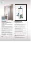
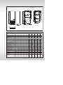
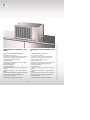
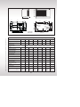
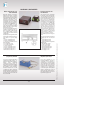
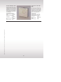
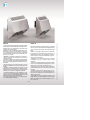
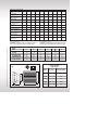
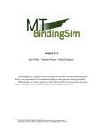
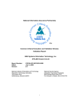
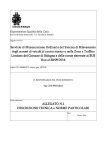
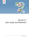
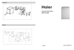
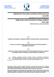
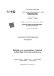
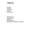
conditioning system
climatizzazione
CONDIZIONATORI D’ARIA - AIR CONDITIONERS
CONDIZIONATORI RAFFREDDATI AD ARIA - AIR-COOLED CONDITIONERS
AIR CONDITIONERS
L’utilizzo di questo tipo di sistema è consigliato nel
caso in cui si debbano dissipare consistenti quantità
di calore, avendo comunque temperature ambiente abbastanza elevate. I condizionatori hanno un limite di
funzionamento dato dalla temperatura esterna che può
variare da+55°C a +20°C. E’ bene considerare anche il
fatto che questo tipo di strumento refrigerante necessita di un uso corretto e di un’adeguata e regolare manutenzione che consiste nella pulizia del filtro aria
(quando presente) e della batteria condensante. E’ opportuno pertanto in fase di acquisto, prevedere anche
un kit di filtri di ricambio, in considerazione del fatto
che l’uso dei normali filtri in commercio è sconsigliato
in quanto hanno un setaccio troppo fine che riduce notevolmente il passaggio dell’aria.
This system is recommended when great quantities
of heat need being dissipated while ambient temperatures are rather high . The conditioners have an
operation limit determined by the outside temperature ranging from +55°C to +20°C. It should also be
considered that this kind of cooling equipment needs
to be properly used and regularly maintained, cleaning the air filter (if any) and the condensing battery.
When buying new equipment, we suggest buying a
set of spare filters: using common filters from the
trade is not advisable as the filtering cloth is too fine
and dramatically limits the airflow.
SISTEMA DI VENTILAZIONE
Filtri e ventilatori possono essere utilizzati nel caso
in cui la temperatura esterna sia inferiore a quella interna del quadro. Necessitano di una manutenzione
minima, consistente in una periodica pulizia dei filtri
ed in un’eventuale sostituzione degli stessi . Sottolineiamo che, per ottenere i migliori risultati possibili,
è bene cercare di creare flussi d’aria che incontrino il
minor numero possibile di ostacoli e che attraversino
completamente il quadro dal basso verso l’alto, poiché l’aria calda tende a salire.
VENTILATION SYSTEM
Filters and fans can be used when the outside temperature is lower than the Panel inside one. Minimum maintenance is required, consisting of a
periodical filter cleaning and replacement, if the need
be. To maximize results, we suggest creating air
flows as free as possible from obstacles, and flowing
through the whole Panel from the bottom upwards,
as hot air tends to rise.
118
Ilinox srl - Parma, Italia - Tel.: +39 0521.813.629 (r.a.) - Fax: +39 0521.813.570 - [email protected] - web page: www.ilinox.com
CONDIZIONATORI D’ARIA
ANTICONDENSATE HEATERS
They are used to solve the problem of condensate
forming due to the very low temperatures reached
when the equipment is stopped. The heaters keep
the inside temperature within safety limits, so avoiding the problem mentioned above.
Ilinox srl - Parma, Italia - Tel.: +39 0521.813.629 (r.a.) - Fax: +39 0521.813.570 - [email protected] - web page: www.ilinox.com
RISCALDATORI ANTICONDENSA
Servono per ovviare al problema della formazione di
condensa durante il periodo di fermo delle apparecchiature, a causa del raggiungimento di temperature
molto basse. I riscaldatori mantengono la temperatura interna entro valori di sicurezza, ovviando così
al succitato inconveniente.
CALCULATION OF HEAT EXCHANGE
Calculating the heat load to be removed represent
the essential step when choosing the cooling system, and four factors should be considered: the
heat dissipated by the equipment inside the panel,
the temperature in the room where the panel is installed, the temperature one wish to keep inside the
panel, control board sizes and set-up conditions.
As far as the quantity of heat produced by the inner
components is concerned, the data shown on the technical sheets of the components themselves must
be checked and evaluated. No need saying that while
making this calculation the possibility of various
units working simultaneously should be taken into
consideration.
Also, as already mentioned, the temperature of the
room where the electric cabinet is installed must be
carefully evaluated. In fact, an exchange takes place
between the panel surfaces and the environment. If
the outside temperature is lower than the inner one,
heat is transferred from inside to outside, and must
be subtracted from the heating load produced by the
components; if, on the contrary, the outside temperature is higher than the inside one, the opposite will
occur, hence the heat absorbed shall be summed to
the heat dissipated by the equipment. In s/s surfaces,
5.5 W/m2K are transmitted per each square meter of
cabinet surface.
The calculation of the over temperature inside the
cabinet must meet CEI 17/43 standard, according to
the cabinet operating conditions.
The relevant calculation sheet in Microsoft® Excel
format is available for easier calculation of the thermal exchange in compliance with the above mentioned standard.
A rough calculation is however possible following
the method below:
CALCOLO DELLO SCAMBIO TERMICO
Il calcolo del carico termico da smaltire è la fase fondamentale per una corretta scelta del sistema di raffreddamento e deve tenere conto di 4 componenti: il
calore dissipato dalle apparecchiature all’interno del
quadro, la temperatura dell’ambiente in cui il quadro
è collocato, la temperatura che si desidera mantenere
all’interno e le dimensioni e condizioni di installazione
del quadro stesso.
Per quanto riguarda la quantità di calore prodotto dai
componenti interni , occorre verificare e valutare i
dati indicati sulle schede tecniche dei componenti
stessi. Naturalmente, nell’effettuare questo calcolo è
importante tenere presente in quale contemporaneità
lavorano i vari apparecchi.
Inoltre, come già accennato, anche la temperatura
dell’ambiente in cui l’armadio è posto deve essere accuratamente valutata. Infatti le superfici del quadro
scambiano calore con l’ambiente stesso. Pertanto se
la temperatura esterna è inferiore a quella interna,
viene ceduto calore dall’interno all’esterno, e quindi
va sottratto al carico termico prodotto dai componenti; viceversa, se la temperatura esterna è superiore a quella interna si verificherà il fenomeno
contrario, quindi si dovrà sommare il calore assorbito
a quello dissipato dalle apparecchiature. Per le superfici inox vengono trasmessi 5,5 W/m2K per ogni
metro quadrato della superficie stessa.
Il calcolo della sorva temperatura all’interno dell’armadio deve essere eseguito secondo la norma CEI
17/43 in base alle condizioni di utilizzo dell’armadio
stesso.
Per effettuare agevolmente il calcolo dello scambio
termico secondo la normativa succitata, è disponibile
su richiesta il foglio di calcolo in formato Microsoft®
Excel.
Per un calcolo di massima è comunque possibile seguire la seguente traccia:
119
TABELLA / TABLE 1
GENERE D’INSTALLAZIONE (DATI RICAVATI DA TABELLA 3 DELLA NORMA CEI 17/43)
INSTALLATION (DATA DERIVED FROM TABLE 3 OF CEI 17/43) STANDARD
• Ae =1.8 x H x (L+P) + 1.4 x L x P
• Ae =1.4 x H x (L+P) + 1.4 x L x P
• Ae = 1.4 x L x (H + P) + 1.8 x P x H
• Ae = 1.8 x L x H + 1.4 x L x P + P x H
• Ae = 1.4 x P x (H + L) + 1.8 x L x H
• Ae = 1.4 x L x (H + P) + P x H
• Ae = 1.4 x P x (H + L) + 1.8 x L x H
• Ae = 1.4 x L x H + 0.7 x L x P + P x H
• Ae =1.4 x H x (L+P) + 1.4 x L x P
LEGENDA:
KEY:
= Larghezza armadio (m)
= Altezza armadio (m)
= profondità armadio (m)
cabinet width (m)
cabinet height (m)
cabinet depth (m)
Isolato esposto su tutti i lati
Individual casing, free on all sides
Pannello posteriore addossato ad una parete
Rear panel set against a wall
Fiancata sinistra addossata ad una parete
Left side set against a wall
Fiancata destra addossata ad una parete
Right side set against a wall
Fiancata sinistra e pannello posteriore addossati ad una parete
Left side and rear panel set against a wall
Fiancata destra e pannello posteriore addossati ad una parete
Right side and rear panel set against a wall
Fiancate destra e sinistra addossate ad una parete
Left and right sides set against a wall
Incassato con fiancate e pannello posteriore addossati ad una parete
Rear panel, left and right sides set against a wall
Completamente incassato con parete superiore coperta
Rear panel, left and right sides set against wall with covered roofing
Per calcolare la potenza raffreddante o riscaldante si
dovrà usare la seguente formula:
The following formula shall be used to calculate the
cooling or heating power:
Pe = PV –( k x Ae x ∆t)
Pe = Pv – (k x Ae x ∆t)
dove Ae è la superficie effettiva dell’armadio ricavata
dalla tabella 1 sopra riportata, ∆t è il valore algebrico
della differenza fra la temperatura interna richiesta e
la temperatura esterna dell’armadio, k è il coefficiente di trasmissione del calore (circa 5.5 W/K m2),
PV è la potenza effettiva dissipata dalle apparecchiature all’interno del contenitore mentre Pe è la potenza
raffreddante o riscaldante necessaria.
Per un calcolo approssimativo della potenza PV è
possibile riferirsi alla tabella “CALORE PRODOTTO
RISPETTO ALLA POTENZA IMPEGNATA”
Where Ae is the cabinet actual surface derived
from Table 1 above, ∆t is the algebraic value of the
gap between the requested inner temperature and
thecabinet outside temperature and, k is the heat
transmission coefficient (approx. 5.5 W/K m2), Pv
is the actual power dissipated by the equipment inside the cabinet, while Pe is the required cooling or
heating power.
Reference to Table “HEAT PRODUCED COMPARED
TO ABSORBED POWER” is possible for a rough
calculation of Pv power.
120
Ilinox srl - Parma, Italia - Tel.: +39 0521.813.629 (r.a.) - Fax: +39 0521.813.570 - [email protected] - web page: www.ilinox.com
L
H
P
italiano-uk 10-01-07:Layout 1
9-02-2007
9:13
Pagina 121
CALORE PRODOTTO RISPETTO ALLA POTENZA IMPEGNATA
HEAT PRODUCED COMPARED TO ABSORBED POWER
COMPONENTE ELETTRICO / ELETTRONICO
ELECTRIC / ELECTRONIC COMPONENT
CALORE % Watt (*)
HEAT % Watt (*)
TRASFORMATORI / INVERTER / AZIONAMENTI
TRANSFORMERS / INVERTERS / DRIVES
ALIMENTATORI DI COMPONENTI ELETTRONICI
FEEDERS OF ELECTRONIC COMPONENTS
BOBINE DI RELÈ E CONTATORI
COILS OF RELAYS AND COUNTERS
LAMPADE A INCANDESCENZA
INCANDESCENT LAMPS
PLC
CONTROLLI NUMERICI
NUMERICAL CHECKS
P (Watt) · 5/100
P (Watt) · 10/100
P (Watt) · 3/100
P (Watt) · 100/100
150 W cadauno / each
200 W cadauno / each
(*) Valori medi, da verificare in base all’apparecchiatura effettivamente utilizzata.
(*) Average values, to be checked according to the equipment actually used.
The example below better explains the matter:
Ilinox srl - Parma, Italia - Tel.: +39 0521.813.629 (r.a.) - Fax: +39 0521.813.570 - [email protected] - web page: www.ilinox.com
Per maggiore chiarezza, proponiamo il seguente esempio:
In a control panel totalling 5.3 m2 of surface, a 15000 W
transformer working at full power, a 1000 watt lamp, a
PLC and a 20000 W inverter working at 80% of its capacity have been installed. According to table 2 we will
get the following total heating load:
In un quadro elettrico con una superficie totale di 5.3 m2
sono stati installati un trasformatore da 15000 W funzionante piena potenza, una lampada da 1000 watt, un PLC
ed un inverter da 20000 W funzionante all’ 80%. Basandoci sulla tabella otterremo il seguente carico totale:
- transformer 15000 x 5/100
= 750 W
- lamp 1000 x 100/100
= 100 W
- PLC 150 x 1
= 150 W
- inverter 20000 x 80/100 X 5/100
= 800 W
----------------------------------------------------------Total inside heat PV
=1800 W =1,80 kW
- trasformatore 15000 x 5/100
= 750 W
- lampada 1000 x 100/100
= 100 W
- PLC 150 x 1
= 150 W
- inverter 20000 x 80/100 X 5/100
= 800 W
----------------------------------------------------------Calore interno tot. PV
= 1800 W = 1.80 kW
Assuming the above Panel is installed in a room with
40°C temperature and that its temperature is kept at
30°C, when these data are related to the total surface of
the panel itself it can be inferred that the thermal power
transmitted to the inside will be as follows:
Ipotizzando che detto quadro sia posto in un ambiente
con temperatura pari a 40°C e che venga mantenuto a
30°C, rapportando questi dati alla superficie totale del
quadro stesso, si evince che verrà trasmessa all’interno
una potenza termica di:
5.3 x 5.5 x -10 = -291.5 W
5.3 x 5.5 x -10 = -291.5 W
The total heating load will be equal to
Pe = 1800 - (-291.5)= 2091.5 W
Il carico termico totale sarà di conseguenza pari a
Pe = 1800- (-291.5)= 2091.5 W
121
Questo sistema di raffreddamento è indicato nel caso in
cui sia necessario mantenere una temperatura interna del
quadro uguale o inferiore a quella esterna. Per evitare di
compromettere l’affidabilità dell’apparecchiatura è bene
valutare attentamente la dimensione del condizionatore,
in modo da scegliere un modello sufficiente a mantenere
la temperatura entro limiti accettabili anche nelle condizioni peggiori, evitando però di sovradimensionarlo. Occorre quindi correlare la temperatura ambiente con quella
interna al quadro, in modo da ottenere quello che viene
comunemente chiamato fattore di correzione, dato necessario per definire la resa nominale di un condizionatore.
Per facilitare la ricerca di detto fattore, riportiamo il seguente grafico:
This cooling system is particularly recommended when
the temperature inside the Panel has to be maintained
equal to or lower than the temperature outside it. To
maximize its reliability, the conditioner should be carefully sized, to get a model big enough to keep the temperature within acceptable limits even in the worst
conditions, while avoiding over-sizing. The ambient
temperature must therefore be related to the Panel inside temperature, to obtain the so-called meter factor,
i.e. the data necessary to determine the conditioner
rated yield. Graph below can help to determine this factor:
Percentuale di umidità relativa 1 80 % 2 60 % 3 40 % 4 30 % 5 20 %
• Sulla destra del diagramma si legge la temperatura interna al quadro
• Sull’asse delle ascisse si legge la temperatura ambiente.
• Il tratteggio delle curve indica la zona che il condizionatore può raggiungere
solo per brevi periodi.
• I numeri cerchiati indicano condizioni limite di lavoro, in funzione della percentuale di umidità relativa esterna. Impostando la temperatura interna al quadro al di sotto dei valori indicati, all’apertura delle porte si forma condensa sui
componenti elettrici causa il raggiungimento del punto di rugiada.
Esempio di correzione sulla resa: per temperatura esterna 45°C ed interna
35°C il fattore di correzione è di 0,85. Quindi per ottenere 1.000 W a queste
condizioni serve un condizionatore con resa nominale (L35L35) di 1.000 /
0,85 = 1,176 W. Viceversa un condizionatore da 1.000 W nominali rende in
queste condizioni 850 W.
1,3
1,2
1,1
1
0,9
45
1
0,8
2
1
2
0,7
40
3
3
35
4
0,6
4
30
0,5
25
5
0,4
20
Temperatura interna al quadro / Temperature inside the Panel (°C)
1,4
Percentage of relative humidity 1 80 % 2 60 % 3 40 % 4 30 % 5 20 %
• The temperature inside the Panel is shown on the right of the chart
• The ambient temperature is shown on the axis of the abscissa
• The dashed curves show the area that conditioner can reach for short times
only
• The encircled figures show the operating limit conditions, according to the
percentage of outside relative humidity. If the temperature inside the Panel is
set below the stated values, condensate will form on the electric components
as doors are opened, because of the dew point being reached.
Example of thermal yield correction: for 45°C outside and 35°C inside temperature, the correction factor is 0.85. To reach these conditions, a conditioner featuring a rated yield of 1000/0.85=1,176 W is required. In contrast, a
1000 W rated power conditioner yields 850 W in these conditions.
0,3
20
25
30
35
40
45
50
55
Temperatura ambiente / Ambient temperature (°C)
122
Ilinox srl - Parma, Italia - Tel.: +39 0521.813.629 (r.a.) - Fax: +39 0521.813.570 - [email protected] - web page: www.ilinox.com
AIR-COOLED CONDITIONERS
Fattore di correzione della potenza frigorifera / Refrigeration power correction factor
CONDIZIONATORI RAFFREDDATI AD ARIA
After this value has been determined, the actual yield of
a conditioner can be fixed according to the following
formula:
Una volta determinato questo valore si puo’ stabilire la
resa effettiva di un condizionatore basandosi sulla seguente formula:
Ad esempio, per una temperatura esterna di 45°C ed inPOTENZA NOMINALE
CONDIZIONATORE
=
POTENZA RAFFREDDANTE
NECESSARIA
FATTORE DI CORREZIONE
CONDITIONER
RATED POWER
REQUIRED COOLING
POWER
METER FACTOR
Example, the meter factor for a 45°C outside temperature and 35°C inside temperature is 0.85. This means
that, in the above conditions, a1000 W rated power
conditioner yields 850 W; if a 1000 W yield is required,
a conditioner featuring a 1176 W rated yield (1000 W
/ 0.85) is required
terna di 35°C, il fattore di correzione è pari a 0.85. Ciò significa che , in dette condizioni, un condizionatore a 1000
W nominali rende 850 W e che se si vuole ottenere una
resa di 1000 W occorre un condizionatore con resa nominale di 1176 W (1000 W / 0.85).
Quando si decide di utilizzare dei condizionatori raffreddati
ad aria, occorre sempre tenere ben presente che:
Ilinox srl - Parma, Italia - Tel.: +39 0521.813.629 (r.a.) - Fax: +39 0521.813.570 - [email protected] - web page: www.ilinox.com
=
When choosing an air-cooled conditioner, it should be
kept into consideration that:
· Sul lato esterno del condizionatore non devono esserci
ostacoli, per evitare una scarsa resa dello stesso o addirittura l’arresto del compressore in conseguenza dell’intervento della protezione
· Il condizionatore standard puo’ funzionare ad una temperatura esterna minima di 20°C e massima di 55°C.
· La temperatura interna del quadro deve essere mantenuta fra i 25°C ed i 45°C. Temperature superiori possono
essere pericolose sia per il condizionatore che per i componenti interni al quadro, mentre temperature inferiori
possono provocare la formazione di condensa sui componenti a seguito dell’apertura delle porte.
· Per ogni condizionatore vengono indicati determinati valori di tensione e di frequenza, con le relative tolleranze
ammesse. Si raccomanda di non superare mai dette tolleranze, per evitare di compromettere l’affidabilità e la funzionalità dell’apparecchiatura.
· Verificare sempre l’eventuale presenza nell’aria di sostanze particolari che potrebbero danneggiare i materiali
di cui è costituito il condizionatore. E’ bene inoltre sempre
controllare se esistono sorgenti di calore in prossimità
dell’apparecchio refrigerante, l’eventuale esposizione ad
agenti atmosferici e la eventuale presenza di correnti vaganti che possono dare origine a fenomeni di corrosione.
Infine, è bene accertarsi che nell’aria non ci sia la presenza
di nebbie di olio o solventi, che potrebbero danneggiare i
normali filtri poliuretanici.
· Nell’aria è sempre presente un certo contenuto di vapore
acqueo, quindi il vapore dell’aria interna al quadro da condizionare condensa sulla batteria fredda del condizionatore stesso. Se l’armadio è a tenuta stagna verso
l’esterno, una volta sottratto quasi tutto questo vapore ,
non si ha più alcuna formazione di acqua di condensa. Se
invece l’armadio è aperto (anche se si tratta di piccole
aperture), si ha una continua produzione di acqua, che
deve essere smaltita tramite l’apposito tubo previsto sul
condizionatore. Detto tubo deve essere libero da otturazioni e non presentare sifoni, per evitare, dopo un certo
tempo, il travaso di condensa all’interno del quadro elettrico. E’ inoltre opportuno prevedere un microinterruttore
sulla porta del quadro, che interrompa automaticamente
il funzionamento del condizionatore, evitando così che
gran parte della potenza frigorifera venga dissipata per far
condensare vapore. E’ ben comunque evitare di aprire e
chiudere in continuazione le porte, altrimenti la protezione
interna del compressore potrebbe interromperne il funzionamento.
· The conditioner outside surface must be free from obstructions, to maximize yield and prevent the compressor being stopped by the safety protection tripping.
· A standard conditioner can work with an outside temperature ranging between 20°C 55°C.
· The Panel inside temperature must be maintained
between 25°C and 45°C. Higher temperatures could
damage both the conditioner and the components inside the Panel, while lower temperatures can cause
condensation on components when the doors are opened.
· Specific voltage and frequency values are given for
each conditioner, with the relevant allowances. We recommend to not exceeding the stated allowances, to
protect the equipment reliability and working conditions.
· Always check for the presence in the air of particular
substances, which could damage the material composing the conditioner. Also, check for the presence of
heat sources next to the cooling unit, for the possible
exposure to weather agents and the possible presence
of stray currents, which could result in corrosion. At
last, you should also check for the presence of airborne oil or solvent mist, which could damage the standard polyurethane filters.
· Since air always contains some steam, the steam contained in the air inside the Panel to be conditioned condenses onto the conditioner battery, which is cold. If
the cabinet is tight towards the inside, no condensate
will form again after most of the steam has been removed. If, in contrast, the cabinet is open (even if openings
are very small) water forms constantly and has to be
disposed of through the pipe fitted to the conditioner
for this purpose. The pipe must be free from clogging
and have no drain-traps, to avoid condensate overflowing into the Control Panel after a certain time. A
micro-switch should also be foreseen on the Panel
door, to stop the conditioner running automatically and
prevent much of the refrigerating power being spoilt to
condense the vapour. Also, doors should not be opened and closed too frequently, or the compressor inner
safety protection could stop operation.
123
SCHEMA FUNZIONALE / OPERATION DIAGRAM
C
E
E
CONDIZIONATORI PER IL MONTAGGIO A PARETE O
SU PORTA SERIE KN
CONDITIONERS FOR WALL OR
DOOR-MOUNTING SERIES KN
CARATTERISTICHE E DOTAZIONI STANDARD:
STANDARD FEATURES AND OUTFIT:
• Montaggio da esterno
• Filtro aria poliuretanico, facilmente estraibile, in
posizione frontale, fissato con una griglia portafiltro
in acciaio inox
• Carpenteria interna in acciaio zincato con lamiera
anti taglio e priva di spigoli vivi o bordi taglienti
• Carteratura in acciaio inox EN 1.4301 - (AISI 304)
finemente satinato e protetto
• Scarico condensa in rame, flangiato alla carpenteria interna e posizionato sul bordo inferiore dell’unità verso l’esterno
• Termostato di controllo interno pretarato a 35°C
• Morsettiera di collegamento interna
• Dissipatore di condensa con “troppo pieno”
• Guarnizione integrale di tenuta IP54 fra condizionatore e quadro elettrico come da norme CEI EN
60529 (CEI 70/1)
• Timer di avviamento compressore (per i modelli
KN30.5 e KN40.5)
• Contattore compressore (per i modelli KN30.5 e
KN40.5)
• Conforme a normativa CE
• Istruzione di uso e manutenzione in 5 lingue
• Outside mounting
• Polyurethane air filter, easily removable, front position, secured by means of a s/s grid
• Inner structure made of galvanised steel with
anti-cutting sheet, free from sharp corners or cutting edges
• Guards made of s/s EN 1.4301 (AISI 304) fine
satin-finished and protected
• Copper steam trap, flanged to the inner structure
and placed on the bottom inner edge
• Thermostat for inner monitoring, pre-set at 35°C
• Inner connection terminal boards
• Condensate remover with “overflow”
• Whole seal IP54 between the conditioner and
the control board according to CEI EN 60529 (CEI
70/1)
• Timer for compressor start-up (for models
KN30.5 e KN40.5)
• Compressor contactor (for models KN30.5 e
KN40.5)
• Meet CE standards
• Use and maintenance manual in 5 languages
124
Ilinox srl - Parma, Italia - Tel.: +39 0521.813.629 (r.a.) - Fax: +39 0521.813.570 - [email protected] - web page: www.ilinox.com
C
Dime di foratura
Drilling template
50
=
340
Ø30
269
130
1000
180
478
170
1204
305
=
270
180
31
460
210
385
400
224
375
A
400
210
202
45
502
n.6 Ø9
95
Ø30
202
B
36
C
n.6 Ø9
65
32.5
36
430
KN30 / 40
Ilinox srl - Parma, Italia - Tel.: +39 0521.813.629 (r.a.) - Fax: +39 0521.813.570 - [email protected] - web page: www.ilinox.com
32.5
335
KN10/15/17/20
Dati tecnici / Technical data
Modello
Model
Resa frigorifera DIN3168 (L35L35)
Refrigerating yield DIN3168 (L35L35)
Potenza totale assorbita
Total absorbed power
Alimentazione elettrica standard
Standard power supply
Frequenza
Frequency
Corrente assorbita allo spunto
Absorbed current at pick-up
Corrente assorbita a regime
Absorbed current in steady conditions
Protezione amperometrica
Ammetric protection
Portata aria evaporatore
Evaporator air rate of flow
Portata aria condensatore
Condenser air rate of flow
Grado di protezione lato quadro
Protection degree – Board side
Gas refrigerante (standard)
Cooling gas (standard)
Temperatura esterna ammessa
Admitted outside temperature
Rumorosità
Noise
Peso approssimativo
Approx. weight
Dimensioni:
Sizes:
A
B
C
KN10.5
KN15.5
KN15.6
KN17.5
KN17.6
KN20.5
KN20.6
KN30.5
KN40.5
W
1.050
1.360
1.360
1.720
1.720
2.000
2.000
2.800
3.800
W
540
664
664
885
885
990
990
1.250
1.350
230 V monofase / single-phase
Hz
50
50
60
50
60
50
60
50
50
A
12,4
15,5
15,5
21,6
21,6
21,9
21,9
27,5
29,3
A
2,9
3,6
3,6
4,7
4,7
4,8
4,8
6
6,4
A
6
6
6
8
8
8
8
16
16
m3/h
300
550
550
550
550
550
550
965
965
m3/h
965
965
965
965
965
965
965
1.500
1.500
IP54
IP54
IP54
IP54
IP54
IP54
IP54
IP54
IP54
R134A
R134A
R134A
R134A
R134A
R134A
R134A
R134A
R134A
°C
20÷55
20÷55
20÷55
20÷55
20÷55
20÷55
20÷55
20÷55
20÷55
dB(A)
62
62
62
62
62
62
62
65
65
kg
38
39
39
39
39
40
40
48
50
mm
mm
mm
1.001
401
238
1.001
401
238
1.001
401
238
1.001
401
238
1.001
401
238
1.001
401
238
1.001
401
238
1.221
507
320
1.221
507
320
125
SCHEMA FUNZIONALE / OPERATION DIAGRAM
E
C
E
C
CONDIZIONATORI EXTRAPIATTI PER MONTAGGIO A
PARETE E SU PORTA - SERIE KS
ULTRA-FLAT CONDITIONERS FOR WALL- AND
DOOR-MOUNTING – SERIES KS
CARATTERISTICHE E DOTAZIONI STANDARD:
• Montaggio da esterno
• Termostato di controllo interno pretarato a 35°C
• Morsettiera di collegamento interna
• Carteratura in acciaio inox EN 1.4301 - (AISI 304) finemente satinato e protetto
• Filtro aria poliuretanico
• Guarnizione di tenuta IP54 fra il condizionatore e il quadro
elettrico come da norme CEI EN 60529 (CEI 70/1)
• Conforme a normative CE
• Istruzioni di uso e manutenzione in 5 lingue
STANDARD FEATURES AND OUTFIT :
• Outside mounting
• Thermostat for inside control, pre-set at 35°C
• Inside connection terminal board
• Guards made of s/s EN 1.4301 - X5 Cr Ni 18/10
(AISI 304) fine satin-finished and protected
• Polyurethane air filter
• Seal IP54 between the conditioner and the Control
Board as per CEI EN 60529 (CEI 70/1) Standard
• Compliant with CE Codes
• Use and maintenance manual in 5 languages
126
Ilinox srl - Parma, Italia - Tel.: +39 0521.813.629 (r.a.) - Fax: +39 0521.813.570 - [email protected] - web page: www.ilinox.com
C
170
170
240
190
100
391
100
30
400
698
1510
657
1510
300
13
257
260
n.6 Ø9
400
115
360
175
357
Ilinox srl - Parma, Italia - Tel.: +39 0521.813.629 (r.a.) - Fax: +39 0521.813.570 - [email protected] - web page: www.ilinox.com
Dime di foratura
Drilling template
Dati tecnici / Technical data
Modello
Model
KS10.5
KS10.6
KS15.5
KS15.6
KS17.5
KS17.6
KS20.5
KS20.6
Resa frigorifera DIN3168 (L35L35)
Refrigerating yield DIN3168 (L35L35)
W
1.000
1.000
1.450
1.450
1700
1700
2.100
2.100
Potenza totale assorbita
Total absorbed power
W
550
550
760
760
980
980
1.085
1.085
Alimentazione elettrica standard
Standard power supply
230 V monofase / single-phase
Frequenza
Frequency
Hz
50
60
50
60
50
60
50
60
Corrente assorbita allo spunto
Absorbed current at pick-up
A
10,5
10,5
15,8
15,8
19
19
21,7
21,7
Corrente assorbita a regime
Absorbed current in steady conditions
A
3
3
3,8
3,8
4,3
4,3
4,7
4,7
Protezione amperometrica
Ammetric protection
A
4
4
6
6
6
6
6
6
Portata aria evaporatore
Evaporator air rate of flow
m3/h
400
400
400
400
400
400
400
400
Portata aria condensatore
Condenser air rate of flow
m3/h
600
600
1200
1200
1200
1200
1200
1200
IP54
IP54
IP54
IP54
IP54
IP54
IP54
IP54
R134A
R134A
R134A
R134A
R134A
R134A
R134A
R134A
20÷55
20÷55
20÷55
20÷55
20÷55
20÷55
20÷55
20÷55
Grado di protezione lato quadro
Protection degree – Board side
Gas refrigerante (standard)
Cooling gas (standard)
Temperatura esterna ammessa
Admitted outside temperature
°C
Rumorosità
Noise
dB(A)
63
63
64
64
66
66
68
68
Peso approssimativo
Approx. weight
kg
50
50
52
52
56
56
60
60
127
CONDITIONERS FOR ROOF-MOUNTING - SERIES
KT
CARATTERISTICHE E DOTAZIONI STANDARD
• Montaggio da tetto (esterno)
• Atti ad essere montati su armadi L. min. 800 P. min 500
• Termostato di controllo interno pretarato a 35°C
• Morsettiera di collegamento interna
• Termostato antigelo
• Carteratura in acciaio inox EN 1.4301 - (AISI 304) finemente satinato e protetto
• Filtro aria poliuretanico
• Golfari di sollevamento
• Timer di avviamento compressore (per i modelli KT30.5
e KT40.5)
• Contattore compressore (per i modelli KT30.5 e
KT40.5)
• Guarnizione di tenuta IP54 fra il condizionatore e il quadro
elettrico come da norme CEI EN 60529 (CEI 70/1)
• Conforme a normative CE
• Istruzioni di uso e manutenzione in 5 lingue
STANDARD FEATURES AND OUTFIT
• Roof- mounting (outside)
• Suitable for cabinets W. min. 800 D min 500
• Thermostat for inside control, preset at 35°C
• Terminal board for inside connection
• Anti-freeze thermostat
• Casing made of s/s EN 1.4301 - X5 Cr Ni 18/10
(AISI 304) fine satin-finished and protected
• Polyurethane air filter
• Hoisting eyebolts
• Compressor start timer (for models KT30.5 e
KT40.5)
• Compressor contactor (for models KT30.5 e
KT40.5)
• Seal IP54 between conditioner and control panels
according to standard CEI EN 60529 (CEI 70/1)
• Meet CE standards
• Use and maintenance manual in 5 languages
128
Ilinox srl - Parma, Italia - Tel.: +39 0521.813.629 (r.a.) - Fax: +39 0521.813.570 - [email protected] - web page: www.ilinox.com
CONDIZIONATORI PER MONTAGGIO A TETTO
SERIE KT
A
B
C
156
32
600
60
60
80
320
Dime di foratura
Drilling template
KT15/17
70
Ø 22
226
186
n.6 Ø 9
107
104
412
18,5
18,5
7x)
42,5
170
Ø30
319,5
Ø9 (
29
107
235
30
363
277,5
336
357,5
244
27
18,5
18,5
466
62
18,5
134
400
110
137,5
18,5
320
27
551
30,5
KT20/30/40
Ilinox srl - Parma, Italia - Tel.: +39 0521.813.629 (r.a.) - Fax: +39 0521.813.570 - [email protected] - web page: www.ilinox.com
Dati tecnici / Technical data
Modello
Model
KT15.5
KT17.5
KT17.6
KT20.5
KT20.6
KT30.5
KT40.5
Resa frigorifera DIN3168 (L35L35)
Refrigerating yield DIN3168 (L35L35)
W
1.360
1.720
1.720
2000
2000
2800
3800
Potenza totale assorbita
Total absorbed power
W
632
900
900
1.015
1.330
1.330
1.680
Alimentazione elettrica standard
Standard power supply
230 V monofase / single-phase
Frequenza
Frequency
Hz
50
50
60
50
60
50
50
Corrente assorbita allo spunto
Absorbed current at pick-up
A
15
21,5
21,5
24,2
24,2
35
36
Corrente assorbita a regime
Absorbed current in steady conditions
A
3,6
4,5
4,5
5
5
8
8,8
Protezione amperometrica
Ammetric protection
A
6
8
8
8
8
16
16
Portata aria evaporatore
Evaporator air rate of flow
m3/h
550
550
550
965
965
965
965
Portata aria condensatore
Condenser air rate of flow
m3/h
965
965
965
965
965
1500
1500
Grado di protezione lato quadro
Protection degree – Board side
IP54
IP54
IP54
IP54
IP54
IP54
IP54
Gas refrigerante (standard)
Cooling gas (standard)
R134A
R134A
R134A
R134A
R134A
R134A
R134A
Temperatura esterna ammessa
Admitted outside temperature
°C
20÷55
20÷55
20÷55
20÷55
20÷55
20÷55
20÷55
Rumorosità
Noise
dB(A)
62
62
62
65
65
65
65
Peso approssimativo
Approx. weight
kg
28
30
30
48
48
50
52
A
mm
301
301
301
409
409
409
409
B
mm
604
604
604
804
804
804
804
C
mm
401
401
401
403
403
403
403
Dimensioni:
Sizes:
129
ACCESSORI / ACCESSORIES
Dispositivo elettronico che integra le
funzioni del termostato di controllo
elettromeccanico perché permette di
leggere istantaneamente la temperatura
reale all’interno del quadro elettrico. La
temperatura viene indicata su un display digitale. Il modulo di diagnostica
è inoltre dotato di tre led che segnalano
rispettivamente la presenze di tensione
sul condizionatore (POWER ON), il filtro aria sporco (FILTER) e il superamento del valore limite di temperatura
all’interno del quadro. Il valore è impostabile da circa 40 a 65°C.
Una serie di contatti liberi da tensione
permettono di interfacciare verso l’esterno i tre segnali succitati. Per utilizzare i suddetti contatti è necessario
collegarsi alla morsettiera esterna del
condizionatore.
Il grado di protezione garantito è IP42.
This electronic device complements
the functions of the electromechanical control thermostat as it allows the
actual temperature inside the control
panel to be read instantly. The temperature is shown on a digital display.
The diagnostic module is also provided with three leds that signal when
the conditioner is on (POWER ON),
when the air filter is dirty (FILTER)
and when the temperature limit value
inside the Panel is exceeded. Set
value can range between 40 and 65°C
approx. A set of non-powered contacts allows the three signals mentioned above to be interfaced to the
outside. Connection to the terminal
board outside the conditioner is required to use the above contacts.
The guaranteed protection degree is
IP 42
La morsettiera centralina è del tipo innesto rapido con 10 pin di collegamento
1 ingresso sonda NTC 22 KΩ
2 ingresso sonda NTC 22 KΩ
3 uscita relè di segnalazione massima temperatura
4 uscita relè filtro sporco
5 uscita relè presenza rete
6 comune uscita relè
7 ingresso segnale filtro sporco
8 ingresso segnale filtro sporco
9 alimentazione scheda 9 V a.c.
10 alimentazione scheda 9 V a.c.
The power unit terminal board quick
coupling type with 10 connection
pins
1 probe input NTC 22 KΩ
2 probe input NTC 22 KΩ
3 output for maximum temperature
signalling relay
4 dirty filter relay output
5 power on relay output
6 relay common output
7 input for dirty filter signal
8 input for dirty filter signal
9 card supply 9 V A.C.
10 card supply 9 V A.C.
Sensor for condensate level
(Acquablock) Art. K007
Sensore di livello condensa
(Acquablock) Art.K007
Level sensor applicable to roofmounting conditioners - series KT, recommended to avoid damage to
equipment due to possible clogging
of the steam trap. As the condensate
reaches the sensor level (connected
to the power unit), the relay stops the
compressor or, if so selected, releases an alarm signal. The Acquablok
supply is 200:240 V AC at 50 Hz
same as the relay output, which current carrying capacity is 10 A. Power
requirement is approx. 1W.
E’ un sensore di livello applicabile ai
condizionatori da tetto serie KT, consigliato per evitare danni alle apparecchiature
dovuti
all’eventuale
ostruzione del tubo di scarico condensa. Quando la condensa raggiunge
il livello del sensore (che è collegato
alla centralina) , il relè provvede all’arresto del compressore o, a scelta,
a segnalare un allarme. L’alimentazione dell’ Acquablok e 200:240 V AC
a 50 Hz come pure l’uscita del relè, la
cui portata è di 10 A. Il consumo elettrico è di circa 1W.
130
Ilinox srl - Parma, Italia - Tel.: +39 0521.813.629 (r.a.) - Fax: +39 0521.813.570 - [email protected] - web page: www.ilinox.com
Electronic diagnostic module ART.K003
Modulo di diagnostica elettronica ART.K003
Thermostats– ART. K020 –
K021
Termostati– ART. K020 – K021
Si tratta di termostati elettromeccanici a
bimetallo. L’art. K020 ha un contatto NO
ed è adatto per il controllo di dispositivi
di raffreddamento o per fornire contatti
d’allarme per massima temperatura,
mentre l’art K021 ha un contatto NC ed
è consigliato per il controllo di dispositivi di riscaldamento.
Bimetal electro-mechanical thermostats. Art. K020 has a NO contact
and is designed to control the cooling
equipment or to provide maximum
temperature alarm contacts, while art.
K021 has a NC contact and is designed to control heating devices.
TECHNICAL DATA
Regulation range
0 to +60°C
Current carrying capacity 6A a 250 V
Switching differential 4°C abt.
Connections
2 cables 2.5
mm2
Interference level
VDE 0875 “N”
Weight
36 gr.
Protection degree
IP30
Ilinox srl - Parma, Italia - Tel.: +39 0521.813.629 (r.a.) - Fax: +39 0521.813.570 - [email protected] - web page: www.ilinox.com
CARATTERISTICHE TECNICHE
Range di regolazione da 0 a +60°C
Portata
6A a 250 V
Differenziale di commutazione
4°C circa
Collegamenti
2 cavi da 2.5
mm2
Livello di interferenza VDE 0875 “N”
Peso
36 grammi
Grado di protezione IP30
131
La tecnologia termoelettrica applicata nelle unità di condizionamento aria per quadri elettrici/elettronici in applicazioni industriali basano il loro funzionamento sul principio delle
pompe di calore ad effetto Peltier.
A differenza dei sistemi tradizionali di refrigerazione/condizionamento a compressore, l’effetto Peltier è di tipo elettronico senza impiego di gas quali CFC o altri. I vantaggi del
sistema termoelettrico rispetto ai sistemi tradizionali a compressore sono i seguenti:
· Affidabilità: essendo di natura elettronica non ha parti meccaniche in movimento e di conseguenza non ha usura ed
esaurimento di carica
· Ingombri e pesi ridotti: di conseguenza si presta ad impieghi
dove il peso e l’ingombro del sistema di dissipazione refrigerazione sono rilevanti agli effetti del funzionamento del sistema finito.
· Alto grado di protezione: il sistema termoelettrico consente
di ottenere un grado di protezione IP55 per i dispositivi interni
al quadro
· Versatilità: le unità termoelettriche da noi fornite sono già
predisposte per accettare la funzione di condiziona-mento/riscaldamento sia in modo automatico con l’aggiunta di un
termostato, che manuale con l’aggiunta di un pulsante.
· Semplicità di installazione: un pratico montaggio a semincasso, una connessione di alimentazione a 24 Volt in corrente
continua, consentono una immediata installazione in quadri
elettrici/elettronici anche di piccola dimensioni.
La scelta del modello adeguato può essere effettuato attraverso l’utilizzo del grafico seguente:
The thermoelectric technology applied to the air conditioning
units for electric/electronic panels in industrial-grade applications is based on the principle of the Peltier-effect heat
pump.
Unlike the conventional compressor-based cooling/conditioning systems, the Peltier effect is electronic with no use of
gas like the CFC or others. The main advantages of the thermoelectric system compared to the traditional compressorbased ones are the following:
· Reliability: they are electronic-based, have no mechanical
moving parts, hence are no subject to wear or charge
exhaustion
· Limited size and weight: ideal where weight and overall dimensions of the refrigerating dissipating system are determinant for the good working of the finished system.
· High protection degree: the thermoelectric system allows
a protection degree IP55 to be achieved for the devices inside
the board.
· Versatility: the thermoelectric units delivered by our company are pre-arranged for the conditioning/heating function,
both in automatic (adding a thermostat) and manual mode
(adding a push botton)
· Easy installation: recessed mounting, 24 Volt D.C. power
supply allow the immediate installation in electric/electronic
Panels, even small-sized. The chart can help you to choose
the correct model:
132
Ilinox srl - Parma, Italia - Tel.: +39 0521.813.629 (r.a.) - Fax: +39 0521.813.570 - [email protected] - web page: www.ilinox.com
PELTIER-EFFECT THERMAL MODULES
SERIES KP
MODULI TERMICI AD EFFETTO PELTIER
SERIE KP
Potenza frigorifera (Watt) / Refrigerating power (Watt)
GRAFICO POTENZA FRIGORIFERA / TEMPERATURA INTERNA QUADRO
Potenza frigorifera = Capacità di dissipazione calore dell’unità termoelettrica
Temperatura interna quadro = Temperatura che si ottiene all’interno del quadro elettri
co/elettronico una volta dissipato il calore prodotto all’interno dai dispositivi installati
150
125
100
KP 150
75
REFRIGERATING POWER CHART/ PANEL INNER TEMPERATURE
Refrigerating power = Heat dissipation capacity of the ther moelectric unit.
Board inside temperature = Temperature obtained inside the electric/electronic
Board after dissi pation of the heat produced inside the devices installed
50
KP 050
25
0
5
10
15
20
25
Differenza tra temperatura ambiente e temperatura interna quadro / Difference between the ambient temperature inside the control panel
STANDARD FEATURES AND OUTFIT
• Semi-recessed mounting
• Guards of EN 1.4301 (AISI 304) s/s fine satin-finished and
protected
• Protection degree: IP55
• Thermal protection at 75° on the hot side in case of fan stop
• Temperature sensor on the hot side
• Temperature sensor on the cold side
Ilinox srl - Parma, Italia - Tel.: +39 0521.813.629 (r.a.) - Fax: +39 0521.813.570 - [email protected] - web page: www.ilinox.com
B
CARATTERISTICHE E DOTAZIONI STANDARD
• Montaggio da semi-incasso
• Carteratura in acciaio inox EN 1.4301 (AISI 304) finemente
satinato e protetto
• Grado di protezione: IP55
• Protezione termica a 75° lato caldo per fermo ventola
• Sensore di temperatura lato caldo
• Sensore di temperatura lato freddo
85
A
Dati tecnici / Technican data
Modello
Model
Potenza frigorifera
W
Refrigerating power
Assorbimento
W
Absorption
Alimentazione elettrica
Power supply
Corrente nominale
A
Nominal current
Temperatura esterna ammessa
°C
Admitted outside temper.
Rumorosità
dB(A)
Noise level
A
Dimensioni
B
Size
C
KP050
KP100
KP200
50
100
200
60
60
168
24 Volt DC +/- 15%
2,5
2,5
7
-40/70
53
55
55
254
290
100
335
290
100
473
390
155
133
C
FILTERS AND VENTILATORS
Sistema di raffreddamento indicato nel caso in cui
la temperatura esterna sia inferiore a quella interna.
Per dimensionare correttamente il ventilatore è necessario conoscere la potenza da dissipare (ved.
scheda CALCOLO TERMICO), la differenza fra temperatura interna ed esterna e estrapolare il valore
della portata d’aria minima del ventilatore dal grafico
a lato.
E’ indispensabili abbinare sempre una griglia con
ventilatore ad una senza, posizionando il ventilatore
in basso e la griglia in alto, sul lato opposto.
Le griglie, tutte con feritoie a gelosia, sono disponibili
sia nella versione in ABS autoestinguente che in
quella in acciaio inox, mentre il corpo interno è sempre in ABS.
Per i casi in cui è richiesto un ingombro minimo e
non è indispensabile un grado di protezione elevato,
è disponibile una griglia extrapiatta con e senza ventilatore.
L’utilizzo di questo sistema di raffreddamento presenta numerosi vantaggi: facilità di installazione ( è
sufficiente forare l’armadio secondo lo schema fornito), manutenzione limitata e costo decisamente
contenuto rispetto agli altri sistemi refrigeranti.
Per evitare problemi e danneggiamenti, si consiglia
sempre di:
Cooling system recommended when the outside
temperature is lower than the inside one. Proper ventilator sizing requires the heat power to be dissipated
to be known (see sheet THERMAL CALCULATION),
as well as the gap between the inside and outside
temperature, while the value of ventilator minimum
air rate of flow will be derived from the chart.
A grid with ventilator must always be matched with
a grid without ventilator, placing the ventilator at the
bottom and the grid on top of the opposite side.
The grids, all louver type, are available both in the
ABS self-extinguishing version and in s/s, while the
inner body, is always inABS.
When minimum overall dimensions are a must, and
high protection degree is not required, an extra-flat
grid is available, with and without ventilator.
This cooling system offers several advantages: easy
installation (drilling the cabinet according to the template supplied is everything you need to do), limited
maintenance and cost rather lower than the other refrigerating systems.
Troubles and damages can be avoided by:
• Making sure the outside temperature is always
134
Ilinox srl - Parma, Italia - Tel.: +39 0521.813.629 (r.a.) - Fax: +39 0521.813.570 - [email protected] - web page: www.ilinox.com
FILTRI E VENTILATORI
lower than the inside one
• Cleaning the filters regularly, and replacing them, if
the need be (the operation can be done even while
the ventilator is running)
• Chose a ventilator slightly oversized compared to
the theoretical calculations: a flow higher than required will cause no damage while it provides a certain
safety margin.
On request, grids and ventilators can be supplied
pre-assembled on control panels.
• Verificare che la temperatura esterna sia sempre inferiore a quella interna
• Pulire periodicamente i filtri ed eventualmente sostituirli (operazione che può essere effettuata anche con
il ventilatore in funzione)
• Scegliere un ventilatore leggermente sovradimensionato rispetto a quanto indicato dai calcoli teorici:
un flusso d’aria superiore a quello richiesto non può
provocare danni e, contemporaneamente, garantisce
un certo margine di sicurezza.
Su richiesta griglie e ventilatori possono essere forniti
già montati sui quadri elettrici.
3000
2500
Potenza termica dissipata / Dissipated thermal power (Watt)
potenza termica dissipata / dissipated thermal power
Ilinox srl - Parma, Italia - Tel.: +39 0521.813.629 (r.a.) - Fax: +39 0521.813.570 - [email protected] - web page: www.ilinox.com
2000
1500
1000
900
K
40 5K
∆T T 3 0K
3
∆
K
∆T
25
∆T
800
700
600
∆T
500
20
K
∆T
400
15
K
∆
T
10
K
300
∆T
5K
200
100
10
20
30
40
50
60 70 80 90 100
200
300
400
500 600 700
Portata ’aria / Air flow rate (m3/h)
portata d’aria / air flow rate (m3/h)
• Preventivamente definire:
- La potenza termica dissipata dai dispositivi elettrici.
- La temperatura massima consentita all’interno dell’armadio.
- La temperatura ambiente massima prevedibile all’esterno dell’armadio.
• Determine in advance:
-The thermal power dissipated by the electric equipment
-The maximum admitted temperature inside the cabinet
- The maximum ambient temperature expected outside the cabinet
• Calcolare ∆T come differenza tra le due temperature.
• Calculate ∆ Tas the difference between the two temperatures
• Incrociare la linea orizzontale relativa alla Potenza termica dissipata con
quella diagonale della differenza di temperatura (∆T). Questo punto di incrocio tra le due variabili determina una linea verticale (rossa) relativa alla portata d’aria in m3/h necessaria alla dissipazione di quanto voluto.
• Cross the horizontal line corresponding to the dissipated thermal power
with the diagonal of temperature difference (∆ T). The crossing point
between the two variables determines a vertical line corresponding to the air
flow in m3/h necessary for the dissipation required.
• Individuare il ventilatore adeguato.
• Choose the suitable fan.
135
KC-A
KQ
GRUPPI VENTILANTI SERIE KC
VENTILATION UNITS SERIES KC
CARATTERISTICHE E DOTAZIONI STANDARD
• Grado di protezione IP44,54 o 55
• Ventilatori assiali con convogliatore, griglia e filtro, funzionanti in immissione
• Motore montato su cuscinetti a sfere con funzionamento in
continuo di 30.000 h.
• Corpo interno griglia in materiale plastico tipo ABS autoestinguente secondo norme UL –94VO con resistenza alle
temperatura da -20°C a +50°C, colore RAL7032
• Griglie esterne con feritoie a gelosia per eventuale drenaggio
della condensa, disponibili sia in acciaio inox EN 1.4301 (AISI
304) finemente satinato e protetto, che in materiale plastico
tipo ABS autoestinguente secondo norme UL –94VO con resistenza alle temperatura da -20°C a +50°C, colore RAL
7032.
• Filtri: trattengono polveri con granulometria fino a 10 micron
• Prodotti conformi alle norme CEI 17-13/1 (IEC439-1), CEI
61-28 (IEC342-1).
STANDARD FEATURES AND OUTFIT
• Protection degree IP44,54 o 55
• Axial ventilators with conveyor, grid and filter, operating on
the inflow side.
• Motor set on ball bearings, with 30,0000-hour non-stop
running.
• Grid inner body made of ABS plastics, self-extinguishing
according to UL –94VO code, standing a temperature range
from -20°C to +50°C, colour RAL7032
• Outside louver type grids for condensate drainage, if the
need be, available both in AISI 304 s/s, fine satin-finished
and protected, and in ABS plastic material, self-extinguishing
according to UL –94VO, standing a temperature range from
-20°C to +50°C, colour RAL 7032.
• Filters: they keep powders with granulometry up to 10 micron
• The product meets CEI 17-13/1 (IEC439-1), CEI 61-28
(IEC342-1) standards.
136
Ilinox srl - Parma, Italia - Tel.: +39 0521.813.629 (r.a.) - Fax: +39 0521.813.570 - [email protected] - web page: www.ilinox.com
KC-P
Dati tecnici / Technical data
Modello
Model
KC12P/44 KC12A/44 KC14P/44 KC14A/44 KC14P/54 KC14A/54 KC20P/44 KC20A/44 KC20P/55 KC20A/55
Tensione aliment
Supply voltage
V
220
220
220
220
220
220
220
220
220
220
Frequenza di rete
Mains Frequency
Hz
50/60
50/60
50/60
50/60
50/60
50/60
50/60
50/60
50/60
50/60
Potenza assorbita
Absorbed power
W
17
17
40
40
40
40
75
75
75
75
Corr.nom.assorb.
Absorbed rated current
A
0.24
0.24
0.15
0.15
0.15
0.15
0.60
0.60
0.60
0.60
42
42
50
50
50
50
50
65
65
65
2250
2250
2320
2320
2320
2320
2750
2750
2750
2750
Portata in aspiraz.libera 3
m /h
Rate of flow at free suction
67
67
230
230
230
230
590
590
590
590
Portata con filtro
Rate of flow with filter
42
42
110
110
85
85
360
360
136
136
Grado di protezione
Protection degree
IP44
IP44
IP44
IP44
IP54
IP54
IP44
IP44
IP55
IP55
Materiale griglia
Grid material
ABS
acc. inox
ABS
acc. inox
ABS
acc. inox
ABS
acc. inox
ABS
acc. inox
dB (A) a 2 m
dB (A) at 2 m
RPM
m3/h
s/s
s/s
s/s
s/s
NOTE: Protection degrees certified by an IMQ or INTEC report available on request.
ATTENTION: Protection degrees are valid only for rate of flow
with filter: they are not referred to rate of flow at free suction.
Dati dimensionali / Dimensions data
Modello
Model
KC12P/44
KC12A/44
KC14P/44-KC14P/54
KC14A/44-KC14A/54
KC20P/44-KC20P/55
KC20A/44-KC20A/55
A
B
C
D
∅E
Kg
130
130
256
256
323
323
140
140
256
256
322
322
24
24
29
29
34
34
74
74
91
91
140
140
114
114
147
147
204
204
0,6
1
1,2
1,9
3
3,9
FILTRI DI RICAMBIO
SPARE FILTERS
KC
Modello
Model
C
D
B
ØE
Ilinox srl - Parma, Italia - Tel.: +39 0521.813.629 (r.a.) - Fax: +39 0521.813.570 - [email protected] - web page: www.ilinox.com
NOTA: Gradi di protezione attestati da una relazione IMQ o INTEC disponibile su richiesta.
ATTENZIONE: i gradi di protezione sono validi per le portate con
filtro e non sono riferiti alle portate in aspirazione libera.
s/s
A
137
Per articolo
For article
Grado di protezione
Protection degree
KF12/44 KC12P / KC12A
IP44
KF14/44 KC14P / KC14A
IP44
KF14/54 KC14P / KC14A
IP54
KF20/44 KC20P / KC20A
IP44
KF20/55 KC20P / KC20A
IP55
KCG-A
KQG
GRUPPI DI AEREAZIONE
AREATION UNITS
CARATTERISTICHE E DOTAZIONI STANDARD
• Grado di protezione IP44,54 o 55
• Corpo interno griglia in materiale plastico tipo
ABS autoestinguente secondo norme UL –94VO
con resistenza alle temperatura da -20°C a +50°C,
colore RAL7032
• Griglie esterne con feritoie a gelosia per eventuale
drenaggio della condensa, disponibili sia in acciaio
inox EN 1.4301 (AISI 304) finemente satinato e
protetto, che in materiale plastico tipo ABS autoestinguente secondo norme UL –94VO con resistenza alle temperatura da -20°C a +50°C, colore
RAL 7032.
• Filtri: trattengono polveri con granulometria fino a
10 micron.
STANDARD FEATURES AND OUTFIT
• Protection degree IP44,54 o 55
• Grid inner body made of ABS plastics, self-extinguishing according to UL –94VO code, standing a
temperature range from -20°C to +50°C, colour
RAL7032
• Outside louver type grids for condensate drainage,
if the need be, available both in AISI 304 s/s, fine
satin-finished and protected, and in ABS plastic material, self-extinguishing according to UL –94VO,
standing a temperature range from -20°C to +50°C,
colour RAL 7032.
• Filters: they keep powders with granulometry up to
10 micron.
138
Ilinox srl - Parma, Italia - Tel.: +39 0521.813.629 (r.a.) - Fax: +39 0521.813.570 - [email protected] - web page: www.ilinox.com
KCG-P
Modello
Model
KCG12P/44
A
B
C
D
Kg
130
140
24
23
0,6
grado protez.
protection degree
44
KCG12A/44
130
140
24
23
1
44
KCG14P/44
256
256
29
23
1,2
44
KCG14P/54
256
256
29
23
1,2
54
KCG14A/44
256
256
29
23
1,9
44
KCG14A/54
256
256
29
23
1,9
54
KCG20P/44
KCG20P/55
323
323
322
322
34
34
30
30
3
3
44
55
KCG20A/44
323
322
34
30
3,9
44
KCG20A/55
323
322
34
30
3,9
55
ABS
acciaio inox
s/s
acciaio inox
s/s
ABS
ABS
acciaio inox
s/s
acciaio inox
s/s
FILTRI DI RICAMBIO
SPARE FILTERS
B
KCG
C D
A
Modello
Model
Per articolo
For article
Grado di protezione
Protection degree
KF12/44
KCG12P / KC12A
IP44
KF14/44 KCG14P / KCG14A
IP44
KF14/54 KCG14P / KCG14A
IP54
KF20/44 KCG20P / KCG20A
IP44
KF20/55 KCG20P / KCG20A
IP55
SCHEMI DI FORATURA / DRILLING TEMPLATES
KC12P-KC12A
KCG12P-KCG12A
KC14P-KC14A
KCG14P-KCG14A
KC20P-KC20A
KCG20P-KCG20A
286,3
220
R12
98,5
116.5
281
297
100
220
=
232
=
R12
124.5
R12
123
N°4 Ø5
115
98,5
Ilinox srl - Parma, Italia - Tel.: +39 0521.813.629 (r.a.) - Fax: +39 0521.813.570 - [email protected] - web page: www.ilinox.com
mat. griglia
grid mat.
ABS
acciaio inox
s/s
ABS
N°8 Ø5
=
=
101,5
232
100
303
139
101,5
GRUPPI VENTILANTI EXTRAPIATTI - KQ12
EXTRA-FLAT VENTILATING UNITS - KQ12
Dati tecnici / Technical data
13
42
55
126
KQ12
126
220/240
Hz
50/60
W
12
A
0.10
A
34
2400
m /h
3
138
IP44
STANDARD FEATURES AND OUTFIT:
• Protection degree IP44
• Extra-flat axial ventilator, alternate flow, working on inflow and suction, complete with polyurethane filter with
Polypropylene fixing grid and accident prevention safety
grid
• Induction motor with ball bearings
• Impedance self-protected
• Die-cast aluminium body
• Fan made of glass fibre reinforced nylon
• Duty temperature –10°C + 70°C
• Grid in black plastic material (polypropylene).
• The products meet the essential requirements of Directive CE 89/392 on machinery, as well as the European
standard EN 292 Part I and II, EN 294 and IEC204-1 and
2
CARATTERISTICHE E DOTAZIONI STANDARD:
• Grado di protezione IP44
• Ventilatori assiali extrapiatti in corrente alternata,
funzionanti in immissione o in estrazione, completi
di filtro in poliuretano con griglia di fissaggio in polipropilene e griglia di protezione anti-infortunistica
• Motore a induzione con cuscinetti a sfere
• Autoprotetti dall’impedenza
• Corpo in alluminio pressofuso
• Ventola in nylon con fibre di vetro
• Temperatura di lavoro –10°C + 70°C
• Griglie in materiale plastico (polipropilene) .
• Prodotti conformi ai requisiti essenziali della direttiva
89/392/CE, relativa alle macchine e alle norme europee
EN 292 parte I e II, EN 294 e alla IEC204-1 e 2
EXTRA-FLAT GRIDS - KQG12
GRIGLIE EXTRAPIATTE - KQG12
126
Ø 115
13
126
105
STANDARD FEATURES AND OUTFIT:
• Protection degree IP44
• Grid in black plastic material (polypropylene).
CARATTERISTICHE E DOTAZIONI STANDARD:
• Grado di protezione IP44
• Griglie in materiale plastico nero (polipropilene) .
Modello
Model
KF12/44
V
FILTRI DI RICAMBIO / SPARE FILTERS
Per articolo
For article
KQ12 / KQG12
140
Grado di protezione
Protection degree
IP44
105
105
119
KQ12
Ø5
Ilinox srl - Parma, Italia - Tel.: +39 0521.813.629 (r.a.) - Fax: +39 0521.813.570 - [email protected] - web page: www.ilinox.com
119
105
Modello
Model
Tensione aliment.
Supply voltage
Frequenza di rete
Mains frequency
Potenza assorbita
Absorbed power
Corr.nom.assorb.
Absorbed rated curr.
dB (A) a 2 m
dB (A) at 2 m
RPM
Portata
Rate of flow
Grado di protezione
Protection degree
STAINLESS STEEL LABYRINTH CASING SERIES KL
Cuffia in acciaio inox EN 1.4301 (AISI 304) , con ingresso
dell’aria dal basso, da applicare sulle griglie: in questo modo
si garantisce una maggiore protezione contro i getti d’acqua
diretti .
EN 1.4301 (AISI 304) S/S casing, with upward air inflow,
for application on grids: they will assuring improved
splash protection.
Articolo
Item
A
B
C
KL10
145
195
32
KL12
200
200
36
KL14
320
320
64
KL20
390
380
100
B
Ilinox srl - Parma, Italia - Tel.: +39 0521.813.629 (r.a.) - Fax: +39 0521.813.570 - [email protected] - web page: www.ilinox.com
CUFFIE A LABIRINTO IN ACCIAIO INOX SERIE KL
C
141
A
VENTILATING UNITS FOR ROOF - KR20
Da utilizzarsi nei casi in cui risulta pratico e conveniente ventilare l’armadio attraverso il tetto. Funziona
in aspirazione.
Risulta di facile applicazione ed il suo ingombro è contenuto, escluso il pacco filtro, all’interno del torrino stesso.
Il carter esterno è realizzato in acciaio inox EN 1-4301 (AISI
304) finemente satinato e protetto.
Il ventilatore è di tipo centrifugo assiale, monofase, montato su cuscinetti a sfera, è conforme ai requisiti essenziali
della direttiva 89/392/CE relativa alle macchine ed alle
norme europee UNI EN 292 parte I, II, UNI EN 294 e alla
CEI 44-5 e 6 (IEC 204-1 e 2).
Il motore, progettato per ottenere alte prestazioni a basso
livello sonoro, ha un grado di protezione IP45 oppure IP55
(a seconda del filtro usato).
For use when ventilating the cabinet through the roof
is practical and convenient. It works on suction.
Easy to apply, its minimum dimensions allow housing
it entirely inside the roof ventilation hoods, except for
the filter pack.
The outside guard is made of EN 1-4301 s/s (AISI
304), finely satin-finished and protected.
The fan is axial-centrifugal, single-phase, set on ball
bearings in compliance with the basic requirements
of Directive 89/392/CE on machinery, and European
Standards UNI EN 292 part I, II, UNI EN 294 and CEI
44-5 and 6 (IEC 204-1 and 2).
Motor protection degree is IP45 or IP55 (it depends
on the filter used), designed for high performances
at low noise level.
142
Ilinox srl - Parma, Italia - Tel.: +39 0521.813.629 (r.a.) - Fax: +39 0521.813.570 - [email protected] - web page: www.ilinox.com
GRUPPI VENTILANTI DA TETTO - KR20
Dati tecnici / Technical data
36
V
230
230
Hz
50/60
50/60
W
55
55
A
0.25
0.25
m3/h
430
430
Rpm
2550
2550
dBA
64
64
Pressione statica (mm H2O)
State pressure (mm H2O)
KR20/45 KR20/55
24
12
0
0
125
250
375
500
Portata (m / h)
3
°C
50
50
Flux / Capacidad (m3 / h)
Qualora si voglia utilizzare il torrino come semplice filtro,
è disponibile senza motore, con grado di protezione
IP45 (art. KRG20/45) oppure IP55 (art. KRG20/55).
Nel caso in cui si voglia aumentare il passaggio d’aria e
non sia richiesto un elevato grado di protezione (max
IP23) è possibile non applicare i gruppi filtranti.
Utilizzato senza filtri diventa un efficace sistema di
aerazione naturale.
La protezione all’acqua è garantita dal sistema a labirinto.
If the roof ventilation hood is expected to work as a
simple filter, it can be delivered without motor, with
protection degre IP45 (Item KRG20/45) or IP55
(Item KRG20/55).
If airflow needs being increased, and high protection
degree is not required (maximum IP 23), the filtering
sets may be omitted.
Using it without filters, becames an efective system
of natural aeration.
Watertightness is ensured by the labyrinth seal system.
50
AREATION HOODS FOR ROOF - KRG20
Ø 273
Ø 367
N.6 fori a 60°
Ø 7
Ø 220
DIMA DI FORATURA
Ø8
16
FILTRI DI RICAMBIO / SPARE FILTERS
Modello
Model
Per articolo
For article
Grado di protezione
Protection degree
KFKR20/45
KFKR20/55
KRG20/45 - KR20/45
KRG20/55 - KR20/55
IP45
IP55
143
98
TORRINI DI AEREAZIONE - KRG20
Ø 240
Ilinox srl - Parma, Italia - Tel.: +39 0521.813.629 (r.a.) - Fax: +39 0521.813.570 - [email protected] - web page: www.ilinox.com
Model
Model
Tensione aliment
Supply voltage
Frequenza
Frequency
Potenza assorbita
Absorbed power
Corrente assorbita
Absorbed current
Portata in aspiraz.libera
Rate of flow at free suction
Giri al minuto
Round per minute
Rumorosità
Noise
Temp. max
Max Temp.
ANTICONDENSATE HEATERS SERIES KM
Da utilizzare nei casi in sui si voglia evitare la formazione di
condensa nei quadri elettrici e quando la temperatura interna
deve essere mantenuta superiore a quella esterna. Sono disponibili in due serie, per poter risolvere adeguatamente il
suddetto inconveniente in quadri di varie dimensioni:
• la serie KMD comprende tre modelli di dimensioni e potenze intermedie, ed è consigliata per quadri di medie dimensioni;
• la serie KMX, composta da due modelli con azione ventilante ed elevata potenza termica, atti ad essere utilizzati per
quadri di medie e grandi dimensioni.
Per scegliere il riscaldatore adatto è ovviamente necessario
conoscere la potenza dissipata dall’armadio (ved. scheda
CALCOLO TERMICO).
Used to prevent condensate forming on control panels, and when the inner temperature has to be kept
higher than the outside one. Two series are available,
to cope with the above problem in panel of different
sizes:
• The KMD series includes three models of little and
average sizes and capacities, suiting Panel of average
dimensions;
• The KMX series, formed by two models with ventilating action and high thermal power, suiting average
and big-sized panels.
To choose the right heater you should know the
power dissipated by the cabinet (see the THERMAL
CALCULATION card).
Model
KMD31 KMD33 KMD34 KMX35 KMX36
Model
Potenza termica
W
60
100
150
250
400
Thermal power (*)
Amperaggio max
A
1.5
2.4
4.5
1.5
2.2
Max amperage
Alimentazione elettrica
140÷250 V AC/DC
220÷230 V – 50/60 Hz
Power supply
Altezza L
mm 140
140
220
178
252
Height L
Peso
Kg
0.5
0.5
0.8
0.95
1.3
Weight
Temp. superficiale
°C
130
130
140
70
95
Surface Temp.
(*) Potenza termica con aria a 20°C all’interno del quadro
Thermal power with air at 20°C inside the panel
KMD
KMX
50
80
80
500
20
L
L
70
STANDARD FEATURES AND OUTFIT
• Fit for installation on 35 mm DIN bar
• Heating element: self-adjusting PTC thermistor
• Radiating element: extruded aluminium
CARATTERISTICHE E DOTAZIONI STANDARD
• Adatti per installazione su barra DIN da 35 mm.
• Elemento riscaldante: termistore PTC autoregolante
• Elemento radiante: estruso in alluminio
144
Ilinox srl - Parma, Italia - Tel.: +39 0521.813.629 (r.a.) - Fax: +39 0521.813.570 - [email protected] - web page: www.ilinox.com
RISCALDATORI ANTICONDENSA SERIE KM