1
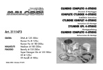
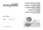
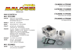
CILINDRO COMPLETO 4-STROKE
Istruzioni di Montaggio
COMPLETE CYLINDER 4-STROKE
malossi.com
Installation Instructions
ZYLINDER KPL 4-STROKE
Montageanleitung
Art. 3113905
SCOOTER 50 4T
APRILIA
SCARABEO (PIAGGIO C373M)
SCARABEO 4V euro 2
SPORTCITY ONE (PIAGGIO C377M)
ITALJET
TORPEDO
MALAGUTI
CENTRO euro 2 (C432M)
CIAK MASTER euro 2
PIAGGIO
FLY
LIBERTY
LIBERTY 4V euro 2
NEW FLY 4V euro 2
ZIP
VESPA
ET4
LX
LX 4V euro 2
Primavera 4V euro 2 (C532M)
S 4V euro 2 (C386M)
Sprint 4V euro 2
11/2014 - 7311576
ITALIANO
ENGLISH
DEUTSCH
2
Egregio Signore, La ringraziamo vivamente per la preferenza accordataci con la scelta dei nostri prodotti.
Il consenso della nostra clientela è lo stimolo più importante per la creatività dei nostri progettisti e di tutta
l’organizzazione della nostra società. La Malossi persegue, fin dai suoi inizi, l’obiettivo di creare prodotti di qualità
superiore, in un rapporto di piena soddisfazione con i suoi acquirenti. I prodotti Malossi sono distribuiti in 57 nazioni
da oltre 3500 punti vendita. La cosa ci riempie di orgoglio e ci spinge ad un impegno sempre maggiore per offrire
prodotti altamente innovativi. La nostra organizzazione ed i nostri tecnici sono a Sua completa disposizione per
fornirLe un servizio moderno ed inappuntabile. Lo scooter equipaggiato con questa trasformazione è destinato ad
un uso esclusivamente agonistico in un circuito chiuso (è assolutamente vietato l’uso stradale). Ricordiamo che
per ottenere prestazioni ottimali è indispensabile avere il veicolo in perfette condizioni in ogni parte meccanica e
rispettare scrupolosamente tutte le istruzioni di montaggio di seguito indicate.
Dear Sir, we thank you very much for the preference you have given us by choosing our products.
The consent of our customers is the most important incentive for the creativity of our designers and of all our
company. Right from the very beginning, the objective of Malossi has been to make products of higher quality, in a
fully satisfying requirements with its customers. Malossi products are sold in 57 countries all over the world with a
distribution system of 3500 sale points. This fills us with pride and leads us to an increasingly greater commitment
to offering innovative products. Our company and our technicians are at your complete disposal to offer you a
modern and faultless service. The scooter fitted out with this kit must only be used for competition on a closed
track (it is strictly forbidden to use it on the road).
Please, take note that to obtain optimum performance all mechanical parts of the vehicle must be in perfect
condition and that the assembly instructions indicated below must be rigorously adhered to.
Sehr geehrter Kunde, vielen Dank, dass Sie sich für unser Fabrikat entschieden haben. Extrem hochwertige
Produkte, die den Ansprüchen des Käufers voll entsprechen sind von jeher oberstes Ziel von Malossi. Derzeit sind
diese in 57 Ländern in über 3500 Verkaufsstellen erhältlich, was uns sehr stolz macht und uns zu immer größeren
Anstrengungen anspornt. Wir freuen uns über Ihr Feedback, denn es liefert unserem gesamten Unternehmen
immer wieder wichtige Anregungen, sowie neue Hinweise für unsere Konstrukteure. Gerne steht Ihnen hierfür und
für etwaige Fragen unser Büro, sowie unser gesamtes Technikteam zur Verfügung.
Ausdrücklich weisen wir darauf hin, dass mit dieser Modifikation Ihr Scooter ausschließlich auf privaten Rennstrecken
betrieben werden darf. (die Verwendung auf öffentlichen Straßen ist streng verboten).
Für optimale Leistungen ist eine perfekte Mechanik Ihres Fahrzeugs unbedingt erforderlich. Weiters sind alle in der
Montageanleitung aufgeführten Punkte genau zu befolgen.
ISTRUZIONI DI MONTAGGIO
OPERAZIONI PRELIMINARI
Lavare accuratamente tutto il veicolo ed in particolar modo il motore.
SMONTAGGIO MOTORE
- Scollegare la batteria.
- Scollegare tutti i cavi dell’impianto elettrico che vanno al motore ed al motorino di avviamento.
- Smontare tutto il gruppo di scarico.
- Togliere la scatola filtro aria.
ASSEMBLY INSTRUCTIONS
PRELIMINARY PROCEDURES
Clean the entire vehicle thoroughly and the entire engine in particular.
ENGINE DISASSEMBLY
- Disconnect the battery.
- Disconnect all cables making up the electrical system that goes to the engine and the starter.
- Disassemble the complete exhaust unit.
- Remove the air filter housing.
MONTAGEANLEITUNG
VORBEREITENDE MASSNAHMEN
Das Fahrzeug und insbesondere den Motor sorgfältig waschen.
MOTORDEMONTAGE
- Die Batterie abklemmen.
- Alle Kabel der Elektroanlage zum Motor und zum Anlasser abklemmen.
- Die gesamte Auspuffanlage ausbauen.
- Das Luftfiltergehäuse entfernen.
3
ITALIANO
ENGLISH
DEUTSCH
4
- Smontare tutto il gruppo impianto di alimentazione dalla testata del motore lasciandolo collegato al telaio.
- Scollegare il sistema frenante posteriore
1) Se il freno posteriore é a ceppi e tamburo basta togliere il cavo di comando
2) Per sistemi frenanti posteriori idraulici o misti (freno stazionamento) bisogna togliere la pinza freno completa,
lasciandola collegata al sistema idraulico del mezzo.
- Togliere la ruota posteriore e le viti o i perni che fissano il motore al telaio e all’ammortizzatore posteriore.
A questo punto avete svincolato il motore dal veicolo, e vi consigliamo di posizionarlo su di un banco di lavoro ben
pulito e pronto alle successive operazioni oppure di bloccarlo su di una morsa.
- Disassemble the fuel system from the cylinder head, leaving it connected to the frame.
- Disconnect the rear braking system
1) If the rear brake is a shoe and drum brake, remove only the control cable
2) For hydraulic or mixed (parking brake) rear braking systems , the complete brake caliper must be removed,
keeping it connected to the vehicle’s hydraulic system.
- Remove the rear wheel and the screws or studs fastening the engine to the frame and rear shock absorber.
At this point, you have released the engine from the vehicle and we advise you to position it on a very clean work
bench ready for the next procedures or to clamp it in a vice.
- Die gesamte Kraftstoffanlage vom Zylinderkopf abnehmen und am Rahmen angeschlossen lassen.
- Die hintere Bremsanlage demontieren.
1) Trommelbremse: das Zugseil ist zu entfernen.
2) Scheibenbremse: die Bremszange ist vollständig zu entfernen, ohne sie jedoch von der Hydraulikanlage des
Fahrzeugs abzutrennen.
- Das Hinterrad und die Schrauben oder Bolzen, die den Motor am Rahmen befestigen, sowie den hinteren
Stoßdämpfer entfernen.
Nun ist der Motor vom Fahrzeug losgelöst; wir empfehlen, ihn für die folgenden Eingriffe auf einer sauberen
Werkbank zu positionieren oder ihn in einem Schraubstock zu befestigen.
SMONTAGGIO GRUPPO TERMICO
- Pulire accuratamente il motore nella zona del basamento cilindro e la testata con appropriati detergenti ed asciugare
il tutto accuratamente.
- Svuotare completamente il motore dall’olio.
- Smontare tutte le parti che compongono il convogliatore aria.
- Togliere il coperchio della testa avendo cura di non danneggiare la guarnizione di tenuta.
- Togliere la candela.
- Allentare, ma non togliere la vite che fissa la corona dentata dell’albero a camme.
- Allentare il dado centrale del tendi catena della distribuzione.
CYLINDER KIT DISASSEMBLY
- Carefully clean the entire engine and especially the area of the cylinder block and head. Use suitable cleaning
detergents and carefully dry all parts.
- Drain all of the oil out of the engine.
- Completely disassemble the air conveyor.
- Remove the cover from the head. Be careful not to damage the seals.
- Remove the spark plug.
- Loosen but do not remove the screw that connects the crown gear to the camshaft.
- Loosen the central nut on the gearing chain tightener.
AUSBAU DES ZYLINDERS
- Den Motor im Bereich des Zylindergehäuses und -kopfs mit geeigneten Reinigungsmitteln sorgfältig reinigen und
trocknen.
- Das Öl völlig aus dem Motor ablassen.
- Alle Kühlerhaubenteile ausbauen.
- Den Zylinderkopfdeckel, ohne den Dichtring zu beschädigen, abnehmen.
- Die Zündkerze entfernen.
- Die Schraube zum Befestigen der Glocke auf der Nockenwelle lockern, aber nicht völlig abschrauben.
- Die zentrale Mutter des Steuerkettenspanners lockern.
5
ITALIANO
ENGLISH
DEUTSCH
6
-
Togliere il gruppo tendi catena svitando le due viti che lo fissano al cilindro originale.
Smontare la corona dentata fissata sull’albero a camme.
Togliere le 2 viti esterne (lato catena) M6.
Svitare i quattro dadi M6 dei prigionieri centrali presenti sul supporto albero a camme.
Smontare la testa ed il cilindro.
Togliere il pistone e lo spinotto facendo molta attenzione affinché non cada qualcosa nel basamento motore.
Per maggior precauzione affinché non entrino corpi estranei nel basamento motore é buona norma chiudere il
passaggio cilindro con uno straccio pulito.
-
Remove the chain tightener unit by unscrewing the two screws that connect it to the original cylinder.
Remove the crown gear attached to the camshaft.
Remove the 2 outside screws M6 (chain side).
Unscrew the four nuts M6 on the central stud bolts on the camshaft support.
Remove the head and the cylinder.
Remove the piston and the pin. Be very careful that nothing falls into the motor base.
As an extra precaution to prevent foreign matter from entering the crankshaft block, it is best to close the block
with a clean cloth.
-
Die Kettenspannergruppe bauen Sie aus, indem Sie die am Originalzylinder befestigten zwei Schrauben lösen.
Den Zahnkranz auf der Nockenwelle abnehmen.
Die zwei äußeren M6-Schrauben (auf der Kettenseite) abschrauben.
Die vier M6-Muttern der zentralen Stehbolzen abschrauben auf den Kurbelwellebereich.
Entfernen Sie den Zylinderkopf sowie den Zylinder.
Den Kolben und den Bolzen entfernen, wobei darauf zu achten ist, dass nichts in das Motorgehäuse fällt.
Sicherheitshalber sollte der Zylinderzugang mit einem sauberen Tuch ausgestopft werden, um das Eindringen
von Fremdkörpern in das Motorgehäuse zu verhindern.
TESTA MOTORE
Se lo scooter non ha percorso molti chilometri si consiglia comunque di effettuare una prova di tenuta delle valvole
seguendo le istruzioni come descritto al paragrafo “Collaudo tenuta valvole”.
Se lo scooter ha percorso parecchi chilometri invece é consigliabile smontare le valvole e controllare che fra stelo
e guide non vi sia eccessivo gioco, che le valvole non siano piegate oppure rechino gradini o che abbiano il fungo
logorato.
Anche in presenza di uno solo di questi casi si consiglia la sostituzione di entrambi i componenti così pure dicasi per le
molle richiamo valvole, se non risultano idonee.
Eventualmente vedere paragrafo “Consigli utili”.
ENGINE HEAD
If the scooter does not have much mileage, we recommend you to perform the valve tightness test in any case,
following the instructions found in the section entitled “Valve tightness test”.
If the scooter has registered a lot of mileage, it is advisable to disassemble the valves and check to ensure that there is
not excessive clearance between the valve stem and the guides, that the valves are not bent or present unevenness or
a worn head. Even if only one of these conditions is found to exist, we advise you to replace both components, as well
as the valve return springs, if the latter are not in perfect condition.
If it is necessary, consult the “Useful suggestions”.
In the event of valve guide replacement for both assembly and disassembly, the head must be heated prior to the
ZYLINDERKOPF
Haben Sie mit Ihrem Scooter noch nicht viele Kilometer zurückgelegt, raten wir Ihnen, den Hinweisen von Abschnitt
„Dichtheitsprüfung der Ventile“ folgend, eine Dichtheitsprüfung der Ventile vorzunehmen.
Wurden jedoch schon zahlreiche Kilometer gefahren, empfehlen wir, die Ventile auszubauen und zu kontrollieren. Zu
prüfen ist, ob zwischen Spindel und Führung kein übermäßiges Spiel vorhanden ist, ob die Ventile nicht geknickt sind
beziehungsweise Stufen aufweisen und ob der Ventilteller abgenutzt ist.
Stellen Sie einen der o.a. Mängel fest sollten Ventile inklusive –führungen ersetzt werden. Bei Verschleißanzeichen der
Ventilfedern sind diese ebenfalls auszutauschen. Siehe dazu Näheres im Abschnitt „Nützliche Hinweise ”.
Wichtig ist es, beim Austausch der Ventilführungen - sowohl beim Aus- als auch beim Einbau den Zylinderkopf mittels
7
ITALIANO
ENGLISH
DEUTSCH
8
In caso di sostituzione delle guide valvola sia per lo smontaggio che per il
montaggio riscaldare preventivamente la testa usando un phon o un fornello
elettrico. Dopo la sostituzione delle guide riprendere le sedi valvola con un
apposita fresa per ripristinarle.
Smerigliare le valvole con pasta abrasiva e ripulire la testata con tutti i suoi
componenti, dalle eventuali incrostazioni residue e dalla pasta abrasiva. Lavare
e sgrassare scrupolosamente poi rimontare le valvole come in origine dopo
averne ben lubrificato gli steli, procedere alla prova di tenuta come descritto al
paragrafo “Collaudo tenuta valvole”.
procedure with a hair-dryer or electric hot plate.
After the replacement of the guides, re-condition the valve seats with a specific
milling machine in order to restore them. Then grind the valve with abrasive
paste and remove any remaining deposits and abrasive paste from the head
and all head components.
Wash and degrease thoroughly then, after having well oiled their shanks, refit
the valves as they were originally fitted. Then proceed with the tightness test
as described in the section entitled “Valve tightness test”.
Föns oder eines elektrischen Ofens vorzuwärmen.
Nach dem Auswechseln der Führungen den Ventilsitz mit einer geeigneten
Fräse bearbeiten. Die Ventile mit Schleifpaste schleifen und den Zylinderkopf
mit all seinen Komponenten von eventuellen Ablagerungen und von der
Schleifpaste reinigen.
Vor dem Einbau die Ventile sorgfältig waschen, entfetten und die Ventilspindeln
schmieren; entsprechend den Hinweisen von Abschnitt „Dichtheitsprüfung der
Ventile“ die Dichtheit der Ventile prüfen.
Fig. 1
Piano di riscontro
Perfectly flat surface plate
Oberfläche genauestens schleifen
Carta abrasiva n.1000
Sheet of 1000 grade emery
Schleifpapier mit Körnung 1000
Attenzione
E’ indispensabile eseguire la spianatura della testa presso un’officina specializzata. In alternativa strisciare la
base di appoggio al cilindro della testa su di un foglio di carta abrasiva (di grana n° 1000) sino a che tutta la
superficie ne risulti interessata; a seguire lavare accuratamente tutta la testata (Fig. 1).
INSERIMENTO DEL CILINDRO
Il cilindro deve entrare liberamente nel carter motore e per evitare seri problemi comportarsi come segue.
Attention
The head lapping in must be done by an authorised workshop. Otherwise clean the base of the cylinder head on
a sheet of 1000 grade emery until it is totally white; then carefully wash the cylinder head (Fig. 1).
INSERTING THE CYLINDER
The cylinder should freely enter the crankcase and to avoid serious problems follow the instructions here below.
Achtung
Das Anpassen des Zylinderkopfs muss durch eine Fachwerkstatt erfolgen. Anderenfalls Schmirgelpapier
der Stärke Nr. 1000 auf eine vollkommen flache Fläche legen und den Kopf an der Auflageseite
zum Zylinder sauber bearbeiten, anschließend den gesamten Zylinderkopf gründlich reinigen
(Fig. 1).
EINSETZEN DES ZYLINDERS
Der Zylinder muss frei in das Motorgehäuse eingefügt werden und um Probleme zu vermeiden, ist folgendermaßen
vorzugehen.
9
ITALIANO
ENGLISH
DEUTSCH
10
PREPARAZIONE AL RIMONTAGGIO
Pulire accuratamente il carter motore nella base di appoggio del cilindro da eventuali residui della guarnizione originale.
Montare la guarnizione di base sul carter motore ed inserirvi le relative bussole di centraggio.
Prima di iniziare il montaggio del gruppo Malossi prendere il cilindro lavarlo e sgrassarlo.
Fare scendere il cilindro lungo i prigionieri di bloccaggio del gruppo termico e senza forzare imboccare il cilindro
nel basamento motore. Verificare che non via siano all’interno del carter parti grezze che impediscano il passaggio
del canotto del cilindro o altri piccoli problemi che non consentono un inserimento libero del cilindro fino a battuta
sul carter motore. In caso vi siano punti di attrito significativi si consiglia di asportarli.
Superata questa fase, sfilare il cilindro e iniziare il montaggio seguendo le istruzioni.
RE-ASSEMBLY PREPARATION
Clean the crankcase in the cylinder support base thoroughly, removing any residue from the original gasket. Mount
the basic gasket on the crankcase and insert the respective truing bushes. Prior to starting to assemble the Malossi
kit, take the cylinder, wash it and degrease it.
Drop the cylinder along the cylinder unit locking stud bolts and without forcing it, fit it in the engine block. Check
to ensure that there are no rough parts inside the crankcase preventing the passage of the cylinder steering shaft
or other minor problems preventing free entry of the cylinder flush with the crankcase. In the event of significant
blocked entry, we advise you to remove useless or damaging parts.
Once this phase has been completed, slide off the cylinder and start the assembly according to this instructions.
VORBEREITUNGEN FÜR DEN WIEDEREINBAU
Das Motorgehäuse im Zylinderbereich sorgfältig von eventuellen Dichtungsrückständen reinigen.
Die Zylinderfußdichtung auf das Motorgehäuse legen und die entsprechenden Zentrierbuchsen einfügen.
Vor der Montage des Malossi- Zylinders waschen und entfetten Sie ihn.
Den Zylinder entlang der Stehbolzen des Motors ohne Kraftanwendung in das Gehäuse einführen. Sicherstellen,
dass im Gehäuseinneren keine Verunreinigungen vorhanden sind, die den Durchgang der Zylinderbüchse behindern
und das freie Einsetzen des Zylinders bis zum Anschlag im Motorgehäuse erschweren. Jegliche Reibungen sind zu
beseitigen. Anschließend den Zylinder herausnehmen und gemäß folgender Anleitung die Montage beginnen.
Montaggio GRUPPO TERMICO
- Pulire accuratamente il nuovo pistone e soffiarlo con aria compressa, controllando che non vi siano corpi estranei
che ostruiscono i forellini di scarico nella cava del II° segmento raschiaolio.
- Montare nel pistone uno dei due fermi spinotto, avendo cura di controllare che sia inserito perfettamente nella
propria sede.
- Inserire il pistone sulla biella e fissarlo con il nuovo spinotto avendo cura di oliarlo preventivamente.
- Inserire il secondo fermo spinotto controllando che sia posizionato correttamente nella propria sede.
CYLINDER KIT assembly
- Clean the new piston thoroughly and blow it with compressed air. Ensure that there is no foreign matter blocking the
small exhaust holes in the slot found on the 2nd scraper ring segment.
- Fit one of the two spin locks in the piston, ensuring that it is perfectly inserted in its seat.
- Insert the piston on the connecting rod and fasten it with the new spin lock. It must be oiled prior to this procedure.
- Insert the second spin lock, ensuring that it is perfectly inserted in its seat.
Montage des ZYLINDERS
- Den neuen Kolben sorgfältig reinigen und mit Druckluft ausblasen; sicherstellen, dass keine Fremdkörper vorhanden
sind, welche die Auslassöffnungen in der Nut des II° Ölabstreifrings verstopfen.
- Eine der beiden Kolbenbolzensicherungen auf den Kolben montieren, wobei auf deren perfekten Sitz zu achten ist.
- Den Kolben auf dem Pleuel montieren und mit dem neuen geölten Bolzen befestigen.
- Die zweite Kolbenbolzensicherung einsetzen und wiederum auf deren korrekten Sitz achten.
11
ITALIANO
ENGLISH
DEUTSCH
12
Montaggio SEGMENTI (Fig. 2)
- Inserire la mollettina del segmento raschiaolio (5) nella terza cava sul pistone, inserire la lamella inferiore (4) e
successivamente la lamella superiore (3) che vanno a comporre il segmento raschiaolio.
- Montare il secondo segmento con la stampigliatura TOP o N rivolta verso la parte superiore del pistone come
indicato in Fig. 3.
- Inserire il primo segmento di compressione con la stampigliatura TOP o N rivolta verso la parte superiore del
pistone come indicato in Fig. 3; posizionare i segmenti come indicato in Fig. 3.
Servendosi della apposita pinza stringi segmenti inserire il nuovo cilindro Malossi, avendolo in precedenza oliato,
mentre si fa avanzare attraverso il passaggio catena, situato nel cilindro, un gancetto con il quale si solleva la
Assembling the PISTON RING (Fig. 2)
- Insert the small scraper ring segment spring (5) in the respective slot found on the piston. Insert the lower reed
(4) and then the upper reed (3), which make up the scraper ring segment.
- Fit the second segment with the word TOP or N facing the upper part of the piston as indicated in the Fig. 3.
- Insert the first compression segment with the word TOP or N facing the upper part of the piston as indicated in
the Fig. 3; place the rings as indicated in the Fig. 3.
Using the special segment gripper pliers, insert the new Malossi cylinder after it has been oiled. A hook serving to
lift the chain itself should advance towards the chain passage found in the cylinder. Then the cylinder is dropped
down to the engine block, ensuring that there is nothing blocking the cylinder from resting perfectly on the base
KOLBENRINGmontage (Fig. 2)
- Die Feder des Ölabstreifrings (5) in der dritten Nut des Kolbens einsetzen; die untere Lamelle (4) und anschließend
die obere Lamelle (3), die den Ölabstreifring bilden, montieren.
- Den zweiten Kolbenring mit der Beschriftung TOP oder N zur Kolbenoberseite – wie in der Fig. 3 gezeigt –
ausgerichtet, montieren.
- Den ersten Verdichtungsring mit der Beschriftung TOP oder N zur Kolbenoberseite – wie in der Fig. 3 gezeigt –
ausgerichtet, einsetzen; die Kolbenringe gemäß Fig. 3 positionieren.
Mit Hilfe der eigenen Kolbenringzange den neuen, vorher geölten Malossi-Zylinder einsetzen, während ein Haken
durch den Kettendurchgang im Zylinder geführt wird, mit dem die Kette angehoben wird. Dann wird der Zylinder
catena stessa; poi si cala il cilindro fino al basamento motore accertandosi che non
vi siano impedimenti al perfetto appoggio del cilindro sulla base del carter motore.
- Montare il pattino guida catena controllando che sia perfettamente alloggiato
nella propria sede.
- Montare la nuova guarnizione di testa e le due bussole di centraggio.
- Infilare la testata sui prigionieri e servirsi di due gancetti per estrarre la catena di
distribuzione agendo dal lato superiore della testa stessa.
- Serrare i quattro dadi M6 dei prigionieri con procedura a croce e con la coppia di
serraggio indicata nella tabella “Dati montaggio”.
of the crankcase.
- Fit the chain guide shoe, checking to ensure that it is perfectly positioned in its
seat.
- Fit the new head gasket and the two truing bushes.
- Insert the head on the stud bolts and use one hook to extract the gearing chain
from the upper circular cover on the head.
- Tighten the four stud bolt M6 proceeding crosswise and with the tightening
torque indicated in the table entitled “Assembly data”.
- Insert the two lateral M6 screws fastening the head to the block and tighten them
bis zum Motorgehäuse eingeschoben, wobei darauf zu achten ist, dass keine
Hindernisse für den Zylinder auf der Motorgehäusebasis vorhanden sind.
- Die Kettenführungsschiene montieren und überprüfen, dass sie in ihrem Sitz
perfekt ausgerichtet ist.
- Die neue Zylinderkopfdichtung und die Zentrierbuchsen montieren.
- Den Zylinderkopf entlang der Stehbolzen einführen und mit Hilfe von zwei Haken
die Steuerkette über die Zylinderkopfoberseite herausziehen.
- Die vier M6-Muttern der Stehbolzen über Kreuz und mit dem in der Tabelle
„Montagedaten” vorgeschriebenen Anzugsmoment festziehen.
Fig. 2
1° Segmento
1st Piston ring
1 Kolbenring
Smusso
Rounding off
Abrundung
2° Segmento
2nd Piston ring
2 Kolbenring
Spigolo
Sharp edge
Scharfe Kante
Fig. 3
TOP o N
TOP o N
Posizione chiusura segmenti /
Position of piston ring closing / Position der Ringstösse
Freccia lato scarico
Arrow exhaust side
Pfeil Auslassrichtung
Posizione delle linee di chiusura dei rispettivi segmenti
Position of closing lines of each piston rings
Position des Ringstösses jedes einzelnen Kolbenrings
13
ITALIANO
ENGLISH
DEUTSCH
14
- Inserire le due viti M6 laterali che fissano il cilindro al basamento e la testata al cilindro e serrarle applicando la
coppia di serraggio indicata nella tabella “Dati montaggio”.
- Montare il convogliatore aria della ventola di raffreddamento.
- Portare l’albero motore al punto morto superiore servendosi di una chiave a T inserita nel dado centrale del
variatore. Per verificare l’esatta posizione del punto morto superiore bisogna allineare l’aletta più lunga della
ventola di raffreddamento tra le due tacche di riferimento presenti sulla parte inferiore del convogliatore aria
(Fig. 4).
- Montare la catena di distribuzione sulla corona dentata ed inserirla sull’albero a camme, allineando la linea di
riferimento con la tacca presente sul gruppo supporto bilancieri.
at the tightening torque indicated in the table entitled “Assembly data”.
- Assemble the cooling fan air conveyor.
- Bring the crankshaft to top dead centre by inserting a T wrench in the variator central nut. To check the exact
position of the top dead centre you have to align the longest blade of the cooling fan between the two notches
on the lower part of the air conveyor (Fig. 4).
- Assemble the gearing chain on the crown gear and insert it on the camshaft, aligning the reference line with the
notch on the equalizer group.
- To insert the crown gear on the camshaft with the gearing chain installed, manually push the top chain tightener
plate (which otherwise blocks assembly of the crown gear) down toward the motor base.
- Die zwei seitlichen M6-Schrauben einsetzen und mit dem in der Tabelle „Montagedaten” vorgeschriebenen
Anzugsmoment festziehen.
- Die Kühlerhaube des Lüfterrads montieren.
- Die Kurbelwelle mittels eines an der Variatorzentralmutter angesetzten T-Schlüssels zum oberen Totpunkt drehen.
Um die exakte Position des oberen Totpunkts zu kontrollieren, richten Sie den längsten Flügel des Lüfterrades
zwischen den beiden Kerben der Kühlhutze aus (Fig. 4).
- Die Steuerkette über den Zahnkranz geben und auf die Nockenwelle stecken, die Referenzlinie ausgerichtet auf
die Kerbe der Kipphenbeln.
- Um den Zahnkranz mit der Steuerkette auf die Nockenwelle zu stecken drücken Sie den oberen Kettenspanner
- Per riuscire ad inserire la corona dentata, con la catena di distribuzione montata,
sull’albero a camme bisogna spingere manualmente verso il basamento del
motore il pattino tendicatena superiore, che altrimenti impedisce il montaggio
della corona.
- Mettere in tensione manualmente la catena di distribuzione agendo dal foro di
montaggio del tendicatena e controllare che la corona dentata sia allineata al
riferimento sul supporto eventualmente spostare la catena di distribuzione di un
dente in più o in meno sulla corona dentata.
- Fare attenzione e controllare spesso che durante la messa in fase dell’albero a
- Tension the gearing chain manually from the chain tightener assembly opening
and check to ensure that the crown gear is aligned with the reference on the
head. If necessary, shift the gearing chain by one tooth more or one less on the
crown gear.
- Be careful to check often to ensure that the crankshaft is not moving during the
timing of the camshaft from the position indicated by the two reference marks
aligned as shown in the Fig. 4.
- Fit the original chain tightener and tighten the central nut on it, compressing the
spring that regulates the gearing chain tension.
Fig. 4
Convogliatore aria
Air convoyor
Kühlhutze
Ventola
raffreddamento
Cooling fan
Lüfterrad
Aletta di riferimento
Reference blade
Referenzflügel
(welcher ansonsten die Montage behindert) manuell Richtung Zylinderfuß.
- Die Steuerkette von Hand spannen, indem über die Montageöffnung des
Kettenspanners eingegriffen wird. Stellen Sie sicher, dass der Zahnkranz mit
dem Bezug auf der Halterung ausgerichtet ist; notfalls die Steuerkette um einen
oder mehrere Zähne des Zahnkranzes versetzen.
- Vorsichtig vorgehen und mehrmals überprüfen, dass während der
Phaseneinstellung der Nockenwelle sich die Kurbelwelle nicht von der Position
der zwei entsprechend Fig. 4 ausgerichteten Bezugszeichen verschiebt.
- Den Originalkettenspanner montieren und die zentrale Mutter festziehen,
15
ITALIANO
ENGLISH
DEUTSCH
16
camme non si muova l’albero motore dalla posizione indicata dai due riferimenti allineati come in Fig. 4.
- Montare il tendicatena originale e serrare il dado centrale dello stesso, comprimendo la molla che regola la
tensione della catena di distribuzione.
- Avvitare la vite centrale sull’albero a camme, bloccando in questo modo la corona dentata nella propria sede.
Chiudere la vite centrale con una coppia di serraggio come indicato nello specchietto dei “Dati montaggio”.
- Con una chiave a bussola con manico a T, agendo sul dado presente sull’albero motore e che fissa il volano,
far compiere all’albero motore 4-5 giri completi e riportarlo al punto morto superiore allineando i riferimenti di
Fig. 4 e controllare che la corona dentata della catena di distribuzione sia ancora allineata con il riferimento sul
supporto bilancieri.
- Screw the central screw on the camshaft, thereby locking the crown gear into its seat. Tighten the central screw
with the tightening torque indicated in the table entitled “Assembly data”.
- Using a socket wrench with a T-shaped handle, and intervening on the nut found on the crankshaft and that
fastens the variator unit, have the engine complete 4-5 complete revolutions and bring it back to the top dead
centre. Align the references shown in the Fig. 4 and check to ensure that the gearing chain crown gear has
remained aligned with the reference mark on the equalizer support.
If the crankshaft is blocked during the rotation, do not attempt absolutely to force it under any circumstances.
Check the timing of the timing system, which evidently was not performed properly. Then repeat the timing
process and follow meticulously the procedure indicated here above.
wodurch die Feder zur Spannungsregelung der Steuerkette zusammengepresst wird.
- Schrauben Sie die zentrale Mutter auf die Nockenwelle, währendessen der Zahnkranz in den Sitz gepresst wird.
Ziehen Sie die Mutter mit dem dafür vorgesehenen Anzugsdrehmoment an (siehe Montagedaten).
- Einen Steckschlüssel mit T-förmigem Griff auf der Mutter, das Lüfterrad auf der Kurbelwelle befestigt, ansetzen
und die Kurbelwelle 4-5 vollständige Umdrehungen durchdrehen, um sie wieder zum oberen Totpunkt zu
bringen; dabei sind die Bezugszeichen von Fig. 4 auszurichten und es ist sicherzustellen, dass der Zahnkranz
der Steuerkette weiterhin mit der Kipphebelnbereich.
Wenn die Kurbelwelle während der Umdrehung blockiert, darf keinesfalls Kraft angewandt werden, sondern es
ist nochmals die offensichtlich nicht korrekt durchgeführte Phaseneinstellung der Steuerung zu überprüfen und
Se durante la rotazione, l’albero motore, si dovesse bloccare assolutamente non tentare di forzarlo ma controllare
la messa in fase della distribuzione che evidentemente non é stata eseguita correttamente e rifare la messa in fase
seguendo scrupolosamente la procedura suindicata.
- Dopo aver verificato che l’albero motore si trovi al punto morto superiore (Fig. 4) controllare ed eventualmente
ripristinare il corretto gioco valvola di scarico e di aspirazione. Il valore del gioco delle valvole é indicato nella
tabella “Dati montaggio”. Per ripristinare il gioco valvole servirsi di uno spessimetro e delle viti di registro presenti sui
bilancieri.
- Rimontare il coperchio testa controllando l’Oring di tenuta ed eventualmente se danneggiato sostituirlo.
- Immettere nel motore la quantità di olio indicata nella tabella “Dati montaggio” del tipo raccomandato dalla casa
- After having checked to ensure that the crankshaft is at the top dead centre (Fig. 4), check and if necessary
correct the exhaust and intake valve for the proper clearance. The value clearance is specified in the table entitled
“Assembly data”. For valve clearance adjustment, you need a feeler gauge and some adjusting screws found on the
equalizers.
- Refit the head cover checking the O-Ring and replacing it if it is damaged.
- Put in the engine the amount of oil indicated in the table entitled “Assembly data”, using the type of oil recommended
by the manufacturer of the vehicle.
- Check the spark plug and if necessary, re-adjust the distance of the electrodes or replace it with one of the types
indicated in the table entitled “Assembly data”.
oben erwähnter Vorgang sehr präzise zu wiederholen.
- Nachdem festgestellt worden ist, dass sich die Kurbelwelle im oberen Totpunkt (Fig. 4) befindet, muss kontrolliert
und evtl. das korrekte Ansaug- und Auslass-Ventilspiel wiederhergestellt werden. Der Wert des Ventilspiels ist
in der Tabelle „Montagedaten” angegeben. Zur Wiederherstellung des Ventilspiels sind eine Fühlerlehre und die
Einstellschrauben auf den Kipphebeln zu verwenden.
- Den Zylinderkopfdeckel montieren, wobei der Dichtungs-O-Ring zu kontrollieren und ggf. zu ersetzen ist.
- Die in der Tabelle „Montagedaten” angegebene Menge Öl der vom Hersteller empfohlenen Marke in den Motor
füllen.
- Die Zündkerze prüfen und eventuell den Elektrodenabstand korrekt einstellen oder mit einer neuen, entsprechend
17
ITALIANO
ENGLISH
DEUTSCH
18
costruttrice del veicolo.
- Controllare la candela e ripristinare eventualmente la distanza degli elettrodi o sostituirla con una nuova del tipo
indicato nella tabella “Dati montaggio”.
- Rimontare il motore sul veicolo e ripristinare tutti i collegamenti con il veicolo come in origine ripetendo a ritroso
tutte le operazioni compiute dopo lo smontaggio.
- Re-mount the engine on the vehicle and reconnect all connections as they were originally.
den in der Tabelle „Montagedaten” angegeben, ersetzen.
- Den Motor im Fahrzeug einbauen und alle Anschlüsse wie ursprünglich wieder herstellen, indem in umgekehrter
Reihenfolge zum Ausbau vorgegangen wird.
DATI MONTAGGIO
- Coppia di serraggio dadi dei prigionieri M 6
- Coppia serraggio viti M6 laterali testa
- Coppia di serraggio vite M6, corona dentata, albero a camme
- Capacità totale olio motore
Tipo: vedi manuale originale “Uso e manutenzione”
- Candela tipo/fabbricante
Distanza elettrodi
- Gioco valvole
ASSEMBLY DATA
- Tightening torque for M6 cap nuts of the stud bolts
- Tightening torque for M6 lateral nuts fastening the head
- Tightening torque for M6 screws, crown gear and camshaft
- Total engine oil capacity
Type: see original “Use and maintenance” manual
- Sparkplug - type/manufacturer
Electrode distance
- Valve clearance
12÷14 Nm (1,2÷1,4 kgm)
12÷14 Nm (1,2÷1,4 kgm)
12÷14 Nm (1,2÷1,4 kgm)
0,85 litri
RG 4 HC/Champion
0,6 ~ 0,7 mm
scarico 0,10 mm
aspirazione 0,10 mm
12÷14 Nm (1.2÷1.4 kgm)
12÷14 Nm (1.2÷1.4 kgm)
12÷14 Nm (1.2÷1.4 kgm)
0.85 liters
RG 4 HC/Champion
0.6 ~ 0.7 mm
exhaust: 0.10 mm
intake: 0.10 mm
MONTAGEDATEN
- Anzugsmoment der M6-Stehbolzenmuttern
12÷14 Nm (1.2÷1.4 kgm)
- Anzugsmoment der seitlichen M6- Zylinderkopf-Schrauben
12÷14 Nm (1.2÷1.4 kgm)
- Anzugsmoment M6-Schraube Zahnkranz-Nockenwelle
12÷14 Nm (1.2÷1.4 kgm)
- Gesamtfassungsvermögen Motoröl
0.85 L
- Typ: siehe Originalhandbuch „Bedienungs- und Wartungsanleitung ”
- Zündkerzentyp/-hersteller
RG 4 HC/Champion
- Elektrodenabstand
0.6 ~ 0.7 mm
- Auslassventilspiel
0.10 mm
- Ansaugventilspiel
0.10 mm
19
ITALIANO
ENGLISH
DEUTSCH
20
COLLAUDO TENUTA VALVOLE
Aspirazione e scarico: effettuare prove una di seguito all’altra.
Versare benzina nel condotto fino a riempirlo soffiare con una pistola ad aria compressa attorno al fungo della
valvola in esame e controllare se all’interno del condotto appaiono delle bollicine d’aria.
In caso affermativo occorre smontare la valvola ed effettuare la smerigliatura anche se questa operazione é già
stata fatta, ed eventualmente ripetere l’operazione fino a quando il fenomeno delle bollicine non verrà a cessare.
Durante la prova controllare che il paraolio applicato alla guida non lasci fuoriuscire carburante altrimenti sostituirlo
con uno nuovo.
VALVE TIGHTNESS TEST
Intake and exhaust: perform the tests one after the other. Pour gasoline into the pipeline until it is filled. Use a
compressed air gun to blow along the head of the particular valve and check whether air bubbles appear inside
the pipeline. If so, the valve must be disassembled and grinding performed even if this procedure has already been
carried out. It may also be necessary to repeat the procedure as many times as needed until the air bubbles no
longer appear. When performing the test, check to ensure that the oil seal on the guide is not leaking fuel. If there
is leakage, replace it with a new one.
DICHTHEITSPRÜFUNG DER VENTILE
Ansaugtrakt und Auslass: die Prüfungen eine nach der anderen durchführen. Die Leitung vollständig mit Benzin
füllen, mit einer Pressluftpistole um den Ventilteller des zu prüfenden Ventils blasen und prüfen, ob sich in der
Leitung Luftbläschen bilden. Ggf. das Ventil ausbauen und erneut schleifen; den Vorgang so lange wiederholen,
bis sich keine Luftbläschen mehr bilden. Während der Prüfung sicherstellen, dass die Ölabdichtung in der Führung
keinen Kraftstoff durchlässt, ansonsten mit einer neuen ersetzen.
CONSIGLI UTILI
Si consiglia di smerigliare le valvole di scarico e aspirazione ogni qualvolta si smonta la testata. La smerigliatura va
eseguita con apposito attrezzo e con una buona pasta abrasiva fine specifica per smerigliatura valvole. Per migliorare
il rendimento del motore é consigliato eseguire una perfetta raccordatura e lucidatura dei condotti di aspirazione e
scarico. Il condotto di aspirazione ottimale é un condotto che tende leggermente a restringersi a partire dalla valvola
del carburatore fino alla valvola di aspirazione con un angolo di chiusura massimo di 2° e nel contempo non deve
presentare nessun tipo di asperità (spigoli, allargamenti bruschi, restringimenti bruschi) pertanto va perfettamente
raccordato. Il condotto di scarico ottimale presenta un andamento leggermente divergente a partire dalla valvola di
scarico (con un angolo di apertura massima di 2°). È esente da qualsiasi asperità e pertanto perfettamente raccordato
USEFUL SUGGESTIONS
We advise you to grind in the exhaust and intake valves whenever the head is disassembled. Grinding must be
carried out using the specific tool and a satisfactory fine abrasive paste designed for grinding valves. To improve the
performance of the engine, it is advisable to perform a perfect jointing and finishing of the intake and exhaust lines. The
best intake line is a line tending to narrow slightly from the carburettor valve on to the intake valve with a maximum cam
angle of 2°. At the same time, it should not have any protuberances of any type (edges, expansions or abrupt narrow
points). Thus, the jointing must be carried out perfectly. The best exhaust line diverts slightly starting from the exhaust
valve (with a maximum opening angle of 2°). No protuberances of any type are present. Therefore, it is perfectly jointed
in all sections up to the exhaust silencer. In this case as well, there must not be any abrupt reductions in passage or
NÜTZLICHE HINWEISE
Die Auslass- und Ansaugventile sollten bei jedem Ausbau des Zylinderkopfs geschliffen werden. Das Schleifen ist mit
Hilfe eines geeigneten Werkzeugs und einer guten und feinen Schleifpaste für Ventile vorzunehmen. Für eine bessere
Motorleistung ist es ratsam, perfekte Anschlüsse und eine optimale Polierung der Ansaug- und Auslasskanäle zu
bewerkstelligen. Der optimale Ansaugkanal ist jener, der vom Vergaserventil ausgehend bis hin zum Ansaugventil mit
einem max. Schließwinkel von 2° leicht verengt und gleichzeitig keinerlei Rauheiten (Ecken, rapide Erweiterungen,
gravierende Verengungen) aufweist; es ist also ein perfekter Anschluss herzustellen. Der optimale Auslasskanal hat vom
Auslassventil ausgehend (mit einem max. Öffnungswinkel von 2°) einen sich leicht erweiternden Verlauf und ist absolut
ohne Rauheiten; er ist also perfekt mit allen Anschlüssen bis hin zum Schalldämpfer verbunden. Auch in diesem Fall
21
ITALIANO
in tutti i passaggi fino al silenziatore di scarico. Anche in questo caso non vi devono essere brusche riduzioni di
passaggio o aumenti di sezioni di passaggio.
ACCENSIONE
L’anticipo da rispettare scrupolosamente è quello originale, dato dalla casa costruttrice.
ENGLISH
CARBURANTE
Usare benzina senza piombo 95 ottani oppure V-power o carburanti similari.
increases in the passage sections.
IGNITION
The original spark advance given by the manufacturer is to be strictly adhered to.
DEUTSCH
FUEL
Use 95 octane lead-free or V-power petrol or similar fuels.
dürfen keine gravierenden Durchgangsverengungen oder -erweiterungen vorhanden sein.
ZÜNDUNG
Die Zündeinstellung muss genau den Original-Herstellerangaben entsprechen.
KRAFTSTOFF
Bleifreies Benzin 95 Oktan, V-Power oder gleichwertiger Kraftstoff.
22
OLIO
Utilizzare il lubrificante raccomandato dalla casa costruttrice del veicolo.
RODAGGIO e MANUTENZIONE
Per il rodaggio e la manutenzione attenersi scrupolosamente al manuale “Uso e manutenzione del veicolo”.
LUBRICANT
We recommend using the type of oil recommended by the manufacturer of the vehicle.
RUNNING IN and MAINTENANCE
For running in and maintenance, follow the instructions found in the “Vehicle use and maintenance” manual
meticulously.
ÖL
Nur das vom Fahrzeughersteller empfohlene Öl verwenden.
EINFAHREN und WARTUNG
Beim Einfahren und Warten des Fahrzeugs sind die Hinweise der „Bedienungs- und Wartungsanleitung” strengstens
zu befolgen.
23
ITALIANO
AVVERTENZE GENERALI
Ogni qualvolta venga smontato il gruppo termico sostituire le guarnizione di testa e base cilindro con una nuova
serie, onde garantire una perfetta tenuta.
Non chiedere mai la massima prestazione al motore prima del raggiungimento della temperatura ottimale
d’esercizio.
ENGLISH
GENERAL CARE
Every time the cylinder kit is disassembled, replace the head and cylinder bottom gaskets with a new series in order
to guarantee a perfect seal.
Never demand maximum performance from the engine until it has reached its optimum working temperature.
DEUTSCH
ALLGEMEINE HINWEISE
Bei jedem Ausbau des Zylinders die Dichtungen an Zylinderkopf und –fuß ersetzen, um perfekte Dichtheit zu
garantieren.
Die volle Motorleistung erst nach Erreichen der optimalen Betriebstemperatur fordern.
24
DATI TECNICI
CILINDRO
Alesaggio Ø 49 mm; Corsa 41,8 mm; Cilindrata 78,8; Rapporto di compressione 1:11,5.
- Materiale: lega primaria di alluminio ad alto tenore di silicio bonificato, canna con riporto di carburi di silicio in una
matrice di nichel galvanico e levigatura incrociata con due passaggi di diamanti con tolleranze ristrettissime
- Lavorazione su macchine utensili a controllo numerico ad elevata precisione
- Accoppiamenti cilindro pistone in selezione di 0,05 mm
- Superfici di scambio termico ricalcolate e maggiorate
TECHNICAL DATA
CYLINDER
Bore: Ø 49 mm; Stroke: 41.8 mm; Displacement: 78.8; Compression ratio: 1:11,5.
- Material: primary aluminium alloy with a high content of hardened and tempered silicon, cylinder liner with silicon
carbide coating in a galvanic nickel die and crossed smoothing with two diamond passages with very limited
tolerances.
- Machining: on machine tools with high precision numerical control
- Cylinder-piston connection with an allowance of 0.05 mm
- Recalculated and upgraded heat exchange surfaces
TECHNISCHE DATEN
ZYLINDER
- Bohrung Ø 49 mm; Hub 41.8 mm; Hubraum 78.8 cm3; Kompressionsverhältnis 11,5:1.
- Material: Erstklassige Aluminiumlegierung mit hohem Anteil an vergütetem Silizium, Laufbuchse mit Siliziumkarbidauflage
mit galvanischer Nickelmatrix beschichtet und gekreuzter Polierung mit zwei Diamantdurchgängen mit sehr geringen
Toleranzen
- Bearbeitung: an NC-Präzisonswerkzeugmaschinen
- Kolben-Zylinder-Anpassung in Abschnitten von 0.05 mm
- Neu berechnete und erhöhte Wärmeaustauschflächen
25
ITALIANO
ENGLISH
DEUTSCH
26
PISTONE
- Super compatto a tre segmenti
- Materiale: lega primaria di alluminio al silicio ad alta resistenza meccanica ed a bassa dilatazione termica con
riporto chimico antiusura sulle pareti di scorrimento
- Lavorazione su macchine a controllo numerico
- Alleggeriti e rinforzati
- Superfici di scambio termico maggiorate
PISTON
- Ultra compact with 3 rings
- Material: special aluminium alloy with a high silicon content, low thermal expansion and a tin facing on the sliding
surfaces
- Machining on machine tools with numerical control
- Lightened and reinforced
- Upgraded heat exchange surfaces
KOLBEN
- Superkompakt mit drei Kolbenringen
- Material: erstklassige Silizium-Aluminium-Legierung mit hohem mechanischem Widerstand, niedriger
Wärmeausdehnung und mit chemischem Abnutzungsschutz auf den Gleitflächen
- Bearbeitung auf NC-Maschinen
- Leicht und verstärkt
- Erhöhte Wärmeaustauschflächen
SEGMENTI
- Speciali ad alto scorrimento e ad altissima resistenza meccanica
- Compressione in ghisa sferoidale S10 cromato
- Raschiaolio in ghisa speciale
- Raschiaolio in tre pezzi in acciaio legato, cromato
PISTON RINGS
- Special piston rings with high sliding ease and very high mechanical resistance
- compression: in chromium-plated S10 spheroidal cast-iron.
- scraper: ring in special cast iron
- 3 pieces scraper ring made of chromium-plated steel alloy
KOLBENRINGE
- Kompression: Spezialkolbenring mit hoher Gleitfähigkeit und sehr hohem mechanischem Widerstand aus nitriertem
Spezialstahl
- Ölabstreifring: aus verchromtem S10-Sphäroguss
- Ölabstreifring: dreiteilig aus verchromtem Legierungsstahl
27
ITALIANO
Speriamo che lei abbia trovato sufficientemente esaustive le indicazioni che precedono. Nel caso in cui qualche punto le risultasse poco
chiaro, potrà interpellarci per iscritto compilando l’apposito modulo inserito nella sezione “contatti” del ns. sito Internet (www.malossi.com).
Ringraziamo fin d’ora per le osservazioni e suggerimenti che vorrà eventualmente farci pervenire. La Malossi si commiata e coglie l’occasione
per complimentarsi ulteriormente con Lei ed augurarle un Buon Divertimento. In BOCCA al LUPO e ... alla prossima.
Le descrizioni riportate nella presente pubblicazione, si intendono non impegnative. Malossi si riserva il diritto di apportare modifiche, qualora
lo ritenesse necessario, al fine di migliorare il prodotto, e non si assume nessuna responsabilità per eventuali errori tipografici e di stampa. La
presente pubblicazione sostituisce ed annulla tutte le precedenti riferite agli aggiornamenti trattati.
GARANZIA. Consulta le condizioni relative alla garanzia sul nostro sito www.malossi.com.
ENGLISH
Prodotti riservati esclusivamente alle competizioni nei luoghi ad esse destinate secondo le disposizioni delle competenti autorità
sportive. Decliniamo ogni responsabilità per l’uso improprio.
We hope you found the above instructions sufficiently clear. However, if any points are not particularly clear, please contact us completing
the special form inserted in the “contact” section on our Internet site (www.malossi.com). We thank you in advance for any comments and
suggestions you may wish to send us. So goodbye from us all at Malossi, and please accept our compliments. Have Fun. GOOD LUCK and
… see you next time.
The descriptions in this publication are not binding. Malossi reserves the right to make modifications, if it considers them necessary, and does
not accept any responsibility for any typographic or printing errors. This publication replaces all previous publications referring to the updating
matters contained therein.
WARRANTY. Look up warranty terms in our website www.malossi.com.
DEUTSCH
These products are reserved solely for races in locations reserved for those purposes and in accordance with the regulations issued
by the competent authorities for sports events. We decline any and all responsibility for improper use.
Wir hoffen, Ihnen mit den hier beschriebenen Anleitungen ausreichend Auskunft gegeben zu haben. Sollten Sie noch Fragen haben, so ersuchen
wir Sie das spezielle Formular auf der “Kontakt” Seite auf unsererer Internetseite auszufüllen.(www.malossi.com). Wir danken Ihnen bereits im
voraus für die an uns gerichteten Tipps und Anmerkungen. Malossi verabschiedet sich nun, wünscht Ihnen viel Spaß und Hals- und Beinbruch
... bis zum nächsten Mal.
Die Beschreibungen in dieser Anleitung sind nicht bindend. Malossi behält sich das Recht vor, notwendige Änderungen durchzuführen und kann
nicht für etwaige inhaltliche oder Druckfehler verantwortlich gemacht werden. Diese Anleitung ersetzt alle vorhergegangenen bezogen auf die
erfolgten Änderungen darin.
GARANTIE. Bitte prüfen Sie unsere Garantiebedingungen auf der Website www.malossi.com.
Diese Produkte sind ausschließlich für Wettkämpfe an den hierfür nach den Vorschriften der zuständigen Sportaufsichtsbehörden
vorgesehenen Austragungsstätten bestimmt. Bei zweckwidriger Verwendung besteht keine Haftung.
28