1
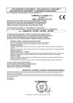
31 9922 CYLINDER KIT
HONDA Foresight 4t 250cc
PIAGGIO X9 4t 250cc
art.
31 9922
Ø 77 aluminium alloy cylinder
Thank you for choosing our modification system. We specify that when scooters are fitted with this modification they must only be used for competition purposes on a closed circuit.
To use your modified vehicle on the road you must have it approved once again, unless it does not contravene the laws in force in the purchaser’s country.
The new cylinder kits from Malossi for Maxi Scooters are at the cutting edge of applied industry technology of cylinder kits for four stroke engines.
The new cylinder kits guarantee complete reliability and long life, at the same time ensuring increased torque and power for your maxi scooter at all engine speeds.
The new cylinder kits from Malossi have been designed and produced to give you top-rate handling
under all conditions, even the most extreme.
We also remind you that in order to obtain top performance all mechanical parts of your vehicle must be
in perfect condition and you must scrupulously observe the assembly instructions.
Technical Data
CYLINDER
Bore Ø 77 mm; Stroke 60 mm; Capacity 279.4; Compression ratio 1:11.
- Material
Hardened and tempered, high silicon content, primary aluminium alloy; cylinder liner with silicon
carbide metal-spray coating on a galvanic nickel matrix, cross honed with two passes with diamonds
for very tight tolerances.
- Machining
On high-precision numerically controlled machine tools
- Cylinder and piston selected for a fit of 0.05 mm.
- Heat exchange surfaces recalculated and increased.
PISTON
- Super compact with three rings
- Material
Special primary silicon alloy with low thermal expansion and tin metal-spray coating on the piston
walls.
- Machining on numerically controlled machine tools
- Lightened and strengthened
- Heat exchange surfaces increased
RINGS
Very smooth running, special rings with very high mechanical strength
S10 chromed, nodular cast iron compression rings and chromed alloy steel three-piece scraper ring
ASSEMBLY INSTRUCTIONS
PRELIMINARY OPERATIONS
Carefully wash the entire vehicle, particularly the engine.
REMOVING THE ENGINE
- Disconnect the battery
- Disconnect all electrical wires that go to the engine and to the starter motor.
- Remove the entire exhaust unit.
- Take off the air filter box.
Products reserved exclusively for competitions in places destined for such use in accordance with the provisions of the relative sporting
authorities. We decline all responsibility for improper use.
ISTRUZIONE
73-9922
pag -11-
31 9922 CYLINDER KIT
HONDA Foresight 4t 250cc
PIAGGIO X9 4t 250cc
-
Remove the fuel feed system from the cylinder head, leaving it connected to the frame.
Disconnect the rear braking system.
1)
If the rear brake is a shoe brake or a drum brake you only have to remove the control
cable.
2)
For hydraulic or mixed braking systems (parking brake) you have to remove the entire
brake pincer, leaving it connected to the vehicle’s hydraulic system.
Drain the coolant circuit using the predisposed plugs.
When the engine is completely drained of coolant, remove all the coolant inlet and outlet hoses from the
engine itself.
Remove the rear wheel and the screws or pins that fix the engine to the frame and to the rear shock
absorber. At this point you have freed the engine from the vehicle. We recommend that you place it on
a well-cleaned workbench or that you clamp it in a vice, ready for the next operations.
DISASSEMBLING THE CYLINDER KIT
- Carefully clean the entire engine, especially the cylinder block area and the cylinder head, using an
appropriate detergent and dry everything carefully.
- Drain the engine completely of oil.
- Remove the inspection plug above the dipstick and bring the crankshaft to top dead centre on the
compression stroke. Make sure of the exact position by lining up the reference line on the flywheel
(marked with the letter T) with the notch on the crankcase (fig. 2), and the groove on the camshaft,
visible through the check hole on the rear cover, with the reference line.
- Remove the rocker cover.
- Loosen the nut in the centre of the camshaft chain tensioner.
- Remove the chain tensioner assembly unscrewing the two screws that fix it to the original cylinder.
- Remove the rear half bearing of the camshaft, loosening the two M6 screws.
- Pull the camshaft chain off the crown gear.
- Remove the two M6 internal bolts on the chain side that fix the cylinder head to the cylinder block.
- Unscrew, with cross procedure, the four M8 box nuts on the stud bolts that fasten the cylinder.
- At this point draw off the cylinder head and the cylinder.
- As an extra precaution it is a good rule to close off the crankcase with a clean rag to stop foreign
bodies falling into it.
ASSEMBLY
CYLINDER HEAD
Even if the scooter has got a low mileage, we recommend doing a valve seal test following the instructions in the “Valve sealing test” paragraph.
With high mileage scooters it is advisable to disassemble the valves and check that there is not too much
play between the rods and the guides, that the valves are not bent or the rods and the valve heads worn.
Even if only one of these components is worn, it is advisable to replace both the valves and the guides;
the same goes for the valve springs.
If necessary see “Useful Advice” on page 5.
If the valve guides need to be replaced we recommend using a hair dryer to heat up the cylinder head
beforehand both for disassembly and assembly. After replacing the valve guides take up the play on the
valve seats with a suitable cutter.
Grind the valves with grinding paste and clean away any encrusted deposits and grinding paste from all
parts of the cylinder head. Wash and degrease the valves with great care, lubricate the rods well and
then refit them as they were. Carry out the valve seal test following the instructions in the “Valve sealing
test” paragraph.
Lay a sheet of 1000 grade emery cloth on a perfectly flat surface plate and clean the base of the cylinProducts reserved exclusively for competitions in places destined for such use in accordance with the provisions of the relative sporting
authorities. We decline all responsibility for improper use.
ISTRUZIONE
73-9922
pag -12-
31 9922 CYLINDER KIT
HONDA Foresight 4t 250cc
PIAGGIO X9 4t 250cc
der head that rests on the cylinder block until it is totally white. Carefully wash the cylinder head.
Fitting the cylinder
The cylinder block must fit freely onto the crankcase. To avoid serious problems proceed as follows.
Preparations for reassembly
Carefully clean away any remains of the original gasket from the surface of the crankcase where the
cylinder block will rest.
Fit the crankcase gasket on the crankcase and insert the spigots.
Before fitting the Malossi cylinder block wash it and degrease it.
Lower the cylinder, without forcing it, along the locking stud bolts until it fits onto the crankcase. Make sure
that there are no components or other small problems in the crankcase that stop the cylinder shell from
seating on it. If there are any significant points of friction it is advisable to remove them.
Once this stage is completed, draw off the cylinder and begin the assembly following the instructions
below.
ASSEMBLING THE CYLINDER KIT
Carefully clean the piston and blow it off with compressed air. Make sure there are no foreign bodies
that obstruct the exhaust holes in the oil scraper ring slot.
Fit one of the two piston clips into the piston, making sure that it is perfectly seated in its housing.
Put the piston on the small end and fix it with the new gudgeon pin, taking care to oil it beforehand.
Fit the other piston clip checking that it is correctly positioned in its housing.
Put the oil scraper ring spring (5) in the appropriate slot on the piston, put in the lower ring (4) and then
the top ring (3) that make up the oil scraper ring.
Fit the second ring with the stamping N pointing towards the top of the piston as shown in Fig. 1.
Fit the first compression ring with the opening not in line with the opening of the second ring.
Position the rings as shown in Fig. 1.
Fit the chain guide checking that it is perfectly housed in its seat.
Oil the new Malossi piston and using the appropriate piston ring clamp insert it into the cylinder block,
while you pass a hook through the chain passage in the cylinder block to hold up the chain itself. Make
sure nothing prevents the cylinder block resting perfectly on the crankcase.
-
-
Fit the new head gasket and the two spigots.
Insert the cylinder head onto the stud bolts and, using the hook, pull out the camshaft chain.
Tighten the four box nuts on the stud bolts equally to the torque wrench settings shown in the
“Assembly Data” table.
Screw in the two M6 side screws that fix the cylinder head to the cylinder block and tighten them to
the torque wrench settings shown in the “Assembly Data” table.
Remove the inspection plug above the dipstick and bring the crankshaft to top dead centre on the
compression stroke. Make sure of the exact position by lining up the reference line on the flywheel
(marked with the letter T) with the notch on the crankcase (fig. 2), and the groove on the camshaft,
visible through the check hole on the rear cover, with the reference line.
Fit the camshaft chain on the camshaft crown gear, lining up the reference line as shown in Fig. 3.
Fix the camshaft to the cylinder head with its half bearing, tightening the two M6 screws to a torque
of 10 Nm.
Manually tension the camshaft chain working on the chain tensioner assembly hole and check that
the crown gear is aligned as shown in Fig. 3. If necessary, move the camshaft chain one tooth
forwards or backwards on the crown gear.
Take care to check often that during engine timing of the camshaft, the crankshaft does not move
from the position shown by the two aligned reference points in Fig. 2.
Products reserved exclusively for competitions in places destined for such use in accordance with the provisions of the relative sporting
authorities. We decline all responsibility for improper use.
ISTRUZIONE
73-9922
pag -13-
31 9922 CYLINDER KIT
HONDA Foresight 4t 250cc
PIAGGIO X9 4t 250cc
-
-
-
-
-
-
Fit the original chain tensioner and tighten its centre nut, compressing the spring that adjusts the tension of the camshaft chain to a torque of 22 Nm.
Rotate the crankshaft through 4 or 5 revolutions using an Allen key with a T-handle on the screw that
fixes the variator set. Take it back to top dead centre aligning the reference lines in Fig. 2 and check
that the crown gear on the camshaft chain is still aligned as shown in Fig. 3.
If the crankshaft blocks during rotation, do not try to force it. Check the engine timing, which has evidently not been done correctly. Redo the engine timing following the above procedure with great
care.
Refit the camshaft cover making sure that the crankshaft is still in the position shown with the letter T
(Fig. 2). Check the O ring seal and if damaged replace it.
Tighten the bolts, with cross procedure, to a torque of 10 Nm.
Valve play adjustment
- Check that the crankshaft has not moved from the position shown in Fig. 2.
- Loosen the two M6 valve play adjustment bolts.
Inlet valve
- Turn the adjuster clockwise (towards the letter I) until the adjuster blocks.
- Turn the adjuster the other way by 1.0 index (anticlockwise towards the letter N).
Exhaust valve
- Turn the adjuster anticlockwise (towards the letter X) until the adjuster blocks.
- Turn the adjuster the other way by 1.0 index (clockwise towards the letter E).
- Tighten the two adjuster locking bolts to a torque of 10 Nm.
Fill the engine with the type of oil recommended by the Manufacturer to the level indicated in the
“Assembly Data” table.
Check the sparkplug, and if necessary reset the electrode gap or replace it with one of the type
shown in the “Assembly Data” table.
Refit the engine to the vehicle and restore all the connections as they were.
COOLING CIRCUIT
Connect the cooling circuit hoses to the engine and fill the circuit as follows:
Using the coolant recommended by the Manufacturer fill the expansion tank, which is on the central tunnel on the opposite side to the petrol cap, to the level marked by Max. (See the vehicle’s maintenance
and user’s manual).
Fill the radiator through the cap on top of the cylinder kit with the appropriate coolant.
Disconnect the small tube near the temperature gauge on the cylinder head and let out all the air in the
cooling circuit and then put the tube back in. Restore the coolant level in the radiator to Max.
Start the engine with the scooter on the stand and leave it to run, revving it up slightly a few times so that
the coolant reaches the working temperature of 60∏70°C. Switch the engine off and bleed again disconnecting the small tube. If necessary restore the level of liquid in the radiator and in the expansion tank.
MAINTENANCE
For running in and maintenance keep scrupulously to the manual “Vehicle’s maintenance and user’s
manual”.
ASSEMBLY DATA
- Torque settings M8 box nuts on the stud bolts
- Torque settings M6 side screws on cylinder head
- Total engine oil capacity
Type: see the “Vehicle’s maintenance and user’s manual”
- Sparkplug type/manufacturer
Electrode gap
24 Nm (2.4 kgm)
10 Nm (1 kgm)
1.3 litres
DPR8EA-9 (NGK)
0.8 ~ 0.9 mm
Products reserved exclusively for competitions in places destined for such use in accordance with the provisions of the relative sporting
authorities. We decline all responsibility for improper use.
ISTRUZIONE
73-9922
pag -14-
31 9922 CYLINDER KIT
HONDA Foresight 4t 250cc
PIAGGIO X9 4t 250cc
VALVE SEALING TEST
Inlet and exhaust: do the tests one after the other.
Pour petrol in the port until it is full and blow compressed air around the valve head with an air gun to
check whether any air bubbles appear inside the port.
If this happens you have to disassemble the valve and grind it again even if you have already done it. If
necessary you will have to repeat the operation until the air bubbles stop appearing. During the test
check that the oil seal on the valve guide does not let any fuel seep through. If this happens replace it
with a new one.
USEFUL ADVICE
We recommend that you grind the inlet and exhaust valves every time you disassemble the cylinder head.
The grinding must be done with an appropriate tool and with a good quality, fine grade grinding paste,
specifically for grinding valves.
To increase engine performance we recommend that the inlet and exhaust ports are perfectly blended
and polished.
The best inlet port is one that tends to taper slightly from the carburettor valve to the inlet valve, by a maximum of 2°, and at the same time does not have any type of irregularities (corners and sudden widening
or narrowing). This is why it must be perfectly blended.
The best exhaust port is one that tapers out slightly from the exhaust valve (by a maximum of 2°) and
which does not have any type of irregularities and so must be perfectly blended right up to the exhaust
silencer. Here also, there must not be any sudden increases or decreases in the cross-section.
GENERAL CARE
Every time the cylinder kit is disassembled replace the head and bottom gaskets of the cylinder block in
order to guarantee perfect sealing.
Do not demand maximum engine performance before the optimum working temperature is reached.
Keep a check on the engine’s lubricating system, the oil level and the quality of the lubricating oil.
WARRANTY
The components for the modification are guaranteed free from manufacturing faults.
Parts considered to be faulty can only be returned, post free, upon our authorisation. The warranty does
not cover damage deriving from seizure of the cylinder kit or any other damage caused by this. We decline all responsibility for improper use of our products.
We hope that you have found the above instructions to be clear enough. If something is not clear to you,
you can contact us by writing or by telephoning during office hours. Thank you in advance for the observations and suggestions that you may wish to make to us.
That’s all from Malossi; we take the opportunity of congratulating you and we hope you have good fun.
GOOD LUCK…. until the next time.
To obtain the complete list of Malossi products for your vehicle, ask your supplier for the Malossi Catalogue
and any updated illustrative brochures.
--------------------------------------------------------------------------------------------------------------------------------------------------------The descriptions given in this publication are not intended to be binding. Malossi reserves the right to make
modifications if considered necessary and not to assume any responsibility for typography and printing
errors. This publication replaces and annuls all previous publications.
Products reserved exclusively for competitions in places destined for such use in accordance with the provisions of the relative sporting
authorities. We decline all responsibility for improper use.
ISTRUZIONE
73-9922
pag -15-
31 9922 GRUPPO TERMICO
HONDA Foresight 4t 250cc
PIAGGIO X9 4t 250cc
fig. 2
fig. 1
POSIZIONE CHIUSURA SEGMENTI-POSITION DE FERMETURE SEGMENTS
RING CLOSURE POSITIONS-SCHLIESSPOSITION KOLBENRINGE
POSICIÓN CIERRE SEGMENTOS
lato scarico-côté échappement
exhaust side-Ablaßseite-lado escape
Posizione delle linee di chiusura dei rispettivi segmenti
Position de la ligne de fermeture des divers segments
Lines of closure of the respective rings
Positionen der Schliesslinien der jeweiligen Kolbenringe
Posición de las líneas de cierre de los respectivos segmentos
fig. 3
Piano testa
Plan de la tête
Cylinder head surface
Ebene Zylinderkopf-Plano culata
Prodotti riservati esclusivamente alle competizioni nei luoghi ad esse destinate secondo le disposizioni delle competenti autorità sportive.
Decliniamo ogni responsabilità per l’uso improprio.
ISTRUZIONE
73-9922
pag -24-