1
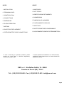
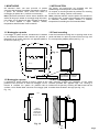
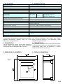
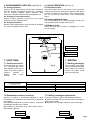
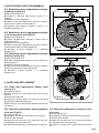
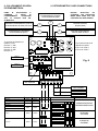
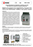
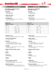
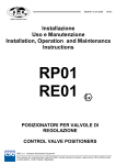
Man140EPne 09/2006
Istruzioni d'Installazione
Uso e Manutenzione
Installation, Operation and
Maintenance Instructions
SERIE 140
Registratori con diagramma circolare
Circular Chart Recorders
INDEX
INDICE
1. INSTALLATION
1. MONTAGGIO
2. TECHNICAL DATA
2. DATI TECNICI
3. IDENTIFICATION
3. IDENTIFICAZIONE STRUMENTO
4. CONNESSIONI
4. CONNECTIONS
5. DIMENSIONI DI INGOMBRO
5. DIMENSIONS
6. FUNZIONAMENTO OROLOGI
6. CLOCK OPERATION
7. SCRITTURA
7. WRITING
8. CHART DISC REPLACEMENT
9. POTENZIOMETRIC CARD CONNECTIONS
In case of mounting or operation problems, please
contact our Local Agent or Service Department,
Cernusco s/N (MI) - Italy.
8. SOSTITUZIONE DISCO DIAGRAMMALE
9. COLLEGAMENTI SCHEDA POTENZIOMETRICA
In caso di problemi di installazione o di funzionamento,
contattare il nostro Agente locale o il nostro Servizio di
Assistenza Tecnica.
OMC s.r.l. - Via Galileo Galilei, 18 - 20060
Cassina de Pecchi (MI) - ITALY
Tel.: (+39) 02.95.28.468 - Fax: (+39) 02.95.21.495 - [email protected]
Pag.2
1. MONTAGGIO
1. INSTALLATION
Gli strumenti Serie 140 sono provvisti di quattro
colonnine standard per l'immediato montaggio a quadro o
a parete. Su richiesta viene fornita una staffa di
montaggio per palina da 2" (verticale o orizzontale).
Nota: particolare attenzione dovrà essere dedicata alla
scelta del luogo più adatto al montaggio degli strumenti,
per evitare che gli apparecchi siano soggetti a vibrazioni
o si trovino esposti a vapori corrosivi, umidità,
temperature ambiente oltre i limiti consentiti.
The Series 140 instruments are equipped with four
standard legs for direct panel or wall mounting.
On request, a mounting bracket is provided for mounting
the unit on a 2" tubing (vertical or horizontal).
Note: particular attention must be paid to the selection of
the mounting site, to protect the equipment from exposure
to vibrations, corrosive vapors, moisture, or ambient
temperatures exceeding the recommended limits.
1.1 Montaggio a quadro
1.2 Panel mounting
Il montaggio a quadro avviene introducendo la cassetta
in una apertura praticata nella lamiera del pannello e
fissandola con le quattro colonnine e le apposite piastrine
di riscontro (vedi Fig. 1.1).
Insert the instrument housing into an opening made in the
panel and fasten it in place by means of the four legs and
the corresponding adapter plates (see Fig. 1.1).
PANNELLO
PANEL
224
Fig. 1.1
DRILLING
R 1,5
192
LEGS
COLONNINE
PIASTRINE DI
RISCONTRO
ADAPTER
PLATES
1.2 Montaggio a parete
1.2 Wall mounting
Il montaggio a parete richiede la posa in opera di due
profilati in ferro provvisti di zanche di fissaggio a muro.
Fissare la cassetta con quattro viti passanti M6 da
avvitare nei fori filettati delle colonnine di montaggio (vedi
Fig. 1.2).
Wall mounting requires the installation of two metal
brackets provided with apposite legs. The housing is
fastened to the panel by screwing four M6 screws into the
threaded holes located in the legs (see Fig. 1.2).
212
179
10
20
MAX
MAX
VISTA
FRONTALE
PROFILATI
BRACKETS
FRONT VIEW
Fig. 1.2
200
MIN
Pag.3
2. DATI TECNICI
2. TECHNICAL DATA
Grado di protezione - Degree of protection
In alluminio pressofuso, verniciatura antiacida
Die cast alumunium with anti corrosive paint
IP54
Montaggio - Mounting
A parete o a quadro - Wall or panel
Connessioni elettriche - Electric connections
morsettiera interna - inside terminal board
Alimentazione elettrica - Electric feeding
24V 50Hz. (110/220V Optional)
Consumo di energia - Power consumption
1 VA
Segnali di ingresso
Input signal ranges
4÷20mA 0÷20mA
1÷5V
Deriva di zero per variazioni temperatura ambiente fra 0°C e 60°C
Zero drift for changes of temperature from 0°C to 60°C
< 0,15% / 10°C
Diametro diagramma - Diameter chart
150 mm
Ampiezza di Registrazione - Useful width
50 mm
Rotazione Diagramma - Chart revolution
1giro / 24 ore (std)
one rotation / 24 hours (std)
Alimentazione Orologio - Chart drive
220V; 110V; 24V - 50Hz-Carica Meccanica-Batteria 1,5V
220V; 110V; 24V - 50Hz or 1.5V Battery or Spring tightening
Limite di incertezza max. - Accuracy
d 1%
Isteresi - Hysteresis
d 0,5%
Linearità - Non linearity
d 0,5%
Ripetibilità - Repeatibility
d 0,5%
Limite temperatura ambiente
Permissible ambient temperature
-20....+ 80 °C
Peso - Weight
a3,5 Kg
Custodia - Body and cover
3. IDENTIFICAZIONE STRUMENTO
T.C.(mV).
PT100 -100÷400°C
Campo: 50°C min e 200°C max.
PT100 -100÷400°C
Span: 50°C min and 200°C max.
3. IDENTIFICATION
I dati necessari all' identificazione dello strumento (modello, The recorder identification data (model, part number,
matricola, alimentazione, elementi, scale, ecc...) sono supply, elements, scales, etc..) are reported on a plate
riportati su una targhetta interna.
located inside the instrument.
4. CONNESSIONI
4. CONNECTIONS
Tutte le connessioni si trovano sul retro dello strumento. I The pneumatic connections are located at the rear bottom
riscontri colorati in prossimità degli attacchi identificano of the instrument housing. The measuring element and the
corresponding writing pens are identified by coloured
l'elemento di misura e le rispettive penne scriventi.
labels, situated near the connections.
5. DIMENSIONI DI INGOMBRO
5. OVERALL DIMENSIONS
Fig. 5
Pag.4
6. FUNZIONAMENTO OROLOGI (vedi Fig. 8).
6.1 Orologio elettrico.
Inserire i cavi di alimentazione dal retro dello strumento,
facendoli passare nell'apposito pressacavo. Collegare i
cavi al morsetto bipolare situato all'interno dello
strumento. Collegare la Massa a Terra all'apposita vite.
6.2 Orologio a carica meccanica.
6. CLOCK OPERATION (see Fig. 8).
6.1 Electrical clock.
Insert the feeders into the rear bottom of the instrument
housing and pass them through the apposite cable gland.
Connect the feeders to the bipolar clamp situated inside
the unit. Connect the earth wire to the corresponding
screw.
Ruotare la ghiera zigrinata (1) (vedi Fig. 8.2) in senso 6.2 Spring tightened clock.
antiorario sino alla completa carica.
Turn the knurled knob (1) counterclockwise until the unit
6.3 Orologio a batteria.
has completely been charged (see Fig. 8.2).
Estrarre il disco disgrammale come descritto al paragrafo 6.3 Battery clock.
8.1, inserire la batteria stilo da 1,5V.
Extract the chart disc as shown in paragraph 8.1. Insert
the 1.5V battery.
PENNA
PEN
PENNARELLO
CARTRIDGE
7. SCRITTURA
7. WRITING
7.1 Cartucce scriventi.
7.1 Writing cartridges
Gli strumenti vengono forniti
con i pennarelli già inseriti
sulle rispettive penne. Per la
messa in funzione, togliere i
cappucci
protettivi
in
plastica
dalle
punte
scriventi.
The recorders are provided
with pre-installed cartridges.
When starting the recorder,
remove the plastic hoods
from the writing tips.
Fig. 6
COLORI COLOURS
TIPO REGISTRATORE
RECORDER TYPE
PRIMA PENNA FIRST PEN
SECONDA PENNA SECOND PEN
A UNA PENNA - SINGLE PEN
BLU' CORTO BLUE SHORT
-
A DUE PENNE - TWO PENS
ROSSO CORTO RED SHORT
BLU' MEDIO BLUE MEDIUM
7.2 Sostituzione cartucce scriventi.
7.2 Writing cartridges replacement.
Qualora la scrittura si presentasse difettosa si dovrà
provvedere alla sostituzione del pennarello, procedendo
come segue:
A) Trattenere saldamente la penna e sfilare il pennarello
da sostituire tirandolo verso il basso.
B) Installare un pennarello nuovo dello stesso colore e
della stessa lunghezza.
If writing is defective, replace the cartridge as follows.
A) Firmly hold back the pen and take off the cartridge by
pulling it downwards.
B) Install the new cartridge with same colour and length.
SHORT
MEDIUM
CORTO
MEDIO
Pag.5
8. SOSTITUZIONE DISCO DIAGRAMMALE
8.1) Sostituzione disco diagrammale orologio
a batterie (vedi fig.8.1)
A) Sollevare l'alzapenna "4".
B) Spostare in direzione della freccia il fermo "1" e
sollevarlo.
C) Estrarre il vecchio diagramma.
D) Infilare il nuovo disco diagrammale nel perno centrale e
inserire il bordo esterno nelle linguette "6".
E) Riportare nella posizione originale il fermo "1" e
abbassare l'alzapenna "4".
4
8.2) Sostituzione disco diagrammale orologio
a carica meccanica (vedi fig.8.2)
A) Sollevare l'alzapenna "4".
B) Svitare completamente ruotando in senso orario la
ghiera zigrinata "1".
C) Estrarre il vecchio diagramma.
D) Infilare il nuovo disco diagrammale nel perno centrale e
inserire il bordo esterno sotto le linguette "6".
E) Riavvitare la ghiera zigrinata "1" e abbassare
l'alzapenna "4".
1
Fig. 8.1
6
8.3) Sostituzione disco diagrammale orologio
elettrico (vedi fig.8.2)
A) Sollevare l'alzapenna "4".
B) Svitare completamente ruotando in senso antiorario la
ghiera zigrinata "1".
C) Estrarre il vecchio diagramma.
D) Infilare il nuovo disco diagrammale nel perno centrale e
inserire il bordo esterno sotto le linguette "6".
E) Riavvitare la ghiera zigrinata "1" e abbassare
l'alzapenna "4".
1
4
8. CHART DISK REPLACEMENT
8.1) Chart disk replacement: battery clock
(see Fig. 8.1)
A) Lift the pen lifter (4).
B) Move the lock (1) in the direction shown by the arrow
and lift it.
C) Remove the chart disk.
D) Install the new chart disk in the central pin and place
the disk edge under the tongues (6).
E) Move the lock (1) to the previous position and lower the
pen lifter (4).
Fig. 8.2
6
8.2) Chart disk replacement: spring tightened 8.3) Chart disc replacement: electrical clock
(see Fig.8.2)
clock (see Fig.8.2)
A) Lift the pen lifter (4).
B) Completely unscrew the knurled knob (1) clockwise.
C) Remove the chart disk.
D) Install the new chart disk in the central pin and place
the disk edge under the tongues (6).
E) Fasten the knurled knob (1) and lower the pen lifter (4).
A) Lift the pen lifter (4).
B) Completely unscrew the knurled knob (1) clockwise.
C) Remove the chart disc.
D) Install the new chart disc in the central pin and place
the disc edge under the tongues (6).
E) Fasten the knurled knob (1) and lower the pen lifter
(4).
Pag.6
9. COLLEGAMENTI SCHEDA
POTENZIOMETRICA
9. POTENZIOMETRIC CARD CONNECTIONS
PRIMA
DI
SELEZIONARE
O
CAMBIARE
IL
MODO
DI
FUNZIONAMENTO
ACCERTARSI
CHE
LA
SCHEDA
NON
SIA
ALIMENTATA
BEFORE
SELECTING
OR
CHANGING THE OPERATION
MODE, MAKE SURE THAT THE
CARD HAS NOT BEEN FEEDED
POTENZIOMETRO (ROSSO)
POTENTIOMETER (RED)
3
CORSORE POTENZIOMETRO (GIALLO)
POTENTIOMETER SLIDER (YELLOW)
2
4
MOTORE (ROSSO)
MOTOR (RED)
POTENZIOMETRO (AZZURRO)
POTENTIOMETER (BLUE)
1
5
MOTORE (ROSSO/NERO)
MOTOR (RED / BLACK)
To reverse the direction of
rotation, invert
the wire "1" with
the wire "3" and
the wire "4" with
the wire "5".
Per invertire il senso di
rotazione invertire
il filo 1 con il filo 3,
il filo 4 con il filo 5
PT2
Fig. 9
PT1
DIP- SWITCH
110V. 50/60Hz
1
2
220V. 50/60Hz
24V. 50/60Hz
RX1
RX2
TR 50°C
TR 100°C
TR 150°C
TR 200°C
TR 250°C
TR 300°C
230K:
180K:
230K:
180K:
100K:
100K:
50K:
50K:
0÷10 V
100K:
100K:
DIP-SWITCH
1
1
4÷20 mA
100K:
2 3
2 3
4 5
4 5
2 3
4 5
TERMORESISTENZA
THERMORESISTANCE
R
X
1
R
X
2
R
X
1
R
X
2
TENSIONE
VOLTAGE
R
X
1
R
X
2
CORRENTE
CURRENT
6
6
100K:
1
INGRESSO - INPUT
6
Pag.7