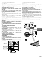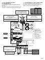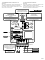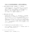
1
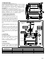
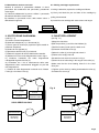
ManREGIne 09/2006
Installazione, Uso e Manutenzione
Registratori Grafici a Traccia Continua
Continuous Pen Recorders
SERIE
SERIE
SERIE
SERIE
SERIE
SERIE
SERIE
150
160
450
460
650EP
950EP
960EP
Installation and Maintenance Instructions
INDEX
INDICE
1. INSTALLATION
1. MONTAGGIO
2. TECHNICAL DATA
2. DATI TECNICI
3. IDENTIFICATION
3. IDENTIFICAZIONE STRUMENTO
4. CONNECTION
4. CONNESSIONI
5. DIMENSIONS
5. DIMENSIONI DI INGOMBRO
6. CLOCK OPERATION
6. FUNZIONAMENTO OROLOGI
7. CHART DRIVE OPERATION
7. TRASPORTATORI
8. WRITING
8. SCRITTURA
9. CHART REPLACEMENT
9. SOSTITUZIONE DIAGRAMMA
10. SENSITIVE ELEMENTS CALIBRATION
10. TARATURA ELEMENTI
11. POTENTIOMETRIC CARD CONNECTION
11. COLLEGAMENTI SCHEDA POTENZIOMETRICA
In case of mounting or operation problems, please
contact our Local Agent or Service Department,
Cernusco s/N - Italy
In caso di problemi di installazione o di
funzionamento, contattare il nostro Agente locale o il
nostro Servizio di Assistenza Tecnica.
OMC s.r.l. - Via Galileo Galilei, 18 - 20060
Cassina de Pecchi (MI) - ITALY
Tel.: (+39) 02.95.28.468 - Fax: (+39) 02.95.21.495 - [email protected]
Pag.2
1. MONTAGGIO
1. INSTALLATION
Gli strumenti sono provvisti di quattro colonnine standard
per l'immediato montaggio a quadro o a parete. Su
richiesta viene fornita una staffa di montaggio per palina da
2" (verticale o orizzontale).
Nota: particolare attenzione dovrà essere dedicata alla
scelta del luogo più adatto al montaggio degli strumenti,
per evitare che gli apparecchi siano soggetti a vibrazioni o
si trovino esposti a vapori corrosivi, umidità, temperature
ambiente oltre i limiti consentiti.
The instruments are equipped with four standard legs for
direct panel or wall mounting. On request a mounting
bracket is provided for mounting the unit on a 2" tubing
(vertical or horizontal).
Note: Particular attention must be paid to the selection of
the mounting site, to protect the equipment from exposure to
vibrations, corrosive vapors, moisture, or ambient
temperatures exceeding the recommended limits.
1.1 Montaggio a quadro
Il montaggio a quadro avviene introducendo la cassetta in
una apertura praticata nella lamiera del pannello e
fissandola con le quattro colonnine e le apposite piastrine
di riscontro (vedi Fig. 1.1).
1.1 Panel mounting
Insert the instrument housing into an opening made in the
panel and fix it in place by means of the four legs and the
corresponding adapter plates (see Fig. 1.1).
PANEL
PANNELLO
DRILLING
FORATURA PANNELLO
318
FORATURA PANNELLO
DRILLING
R 1,5
368
Fig. 1.1
R 1,5
238
310
COLONNINE
SERIE
150 - 160 - 650EP
PIASTRINE DI
RISCONTRO
LEGS
ADAPTER
PLATES
SERIE
450 - 460 - 950EP - 960EP
20
MAX
1.2 Montaggio a parete
Il montaggio a parete richiede la posa in opera di due
profilati in ferro provvisti di zanche di fissaggio a muro.
Fissare la cassetta con quattro viti passanti M6 da avvitare
nei fori filettati delle colonnine di montaggio (vedi Fig. 1.2).
1.2 Wall mounting
Wall mounting requires the installation of two metal
brackets provided with apposite legs. The housing is
Fig. 1.2
fastened to the panel by screwing four M6 screws into the
threaded holes located in the legs (see Fig. 1.2).
200
MIN
Pag.3
2. DATI TECNICI
2. TECHNICAL DATA
Custodia
Body and cover
Grado di protezione
Degree of protection
Montaggio
Mounting
Limite di incertezza max.
Accuracy
Isteresi
Hysteresis
Linearità
Non linearity
Ripetibilità
Repeatability
Limite temperatura ambiente
Room temperature range
In alluminio pressofuso, verniciatura antiacida
Die cast alumunium, corrosion resistant paint
IP54
A parete o a quadro
Wall or panel
d 1%
d 0.5%
d 0.5%
d 0.5%
-20....+ 80 °C
SERIE 150 - 650EP
Diametro diagramma
Chart diameter
Ampiezza di Registrazione
Useful width
Rotazione Diagramma
Chart revolution
Alimentazione orologio
Chart drive
Peso
Weight
SERIE 450 - 950EP
200mm
76mm
1 giro / 24 ore (std)
1 revolution / 24 hours (std)
Carica Meccanica o Batteria 1,5V
1.5V Battery or Spring tightening
~6 Kg
Diametro diagramma
Chart diameter
Ampiezza di Registrazione
Useful width
Rotazione Diagramma
Chart revolution
Alimentazione orologio
Chart drive
Peso
Weight
SERIE 160
Larghezza diagramma
Chart width
Ampiezza di Registrazione
Useful width
Avanzamento Diagramma
Chart speed
Alimentazione trasportatore
Chart drive
Peso
Weight
240mm
100mm
1 giro / 24 ore (std)
1 revolution / 24 hours (std)
Carica Meccanica o Batteria 1,5V
1.5V Battery or Spring tightening
~9 Kg
SERIE 460 - 960EP
120mm
100mm
20mm / ora (std)
20mm / hour (std)
Carica Meccanica o 24 V 50Hz
24 V 50Hz or Spring tightening
~6 Kg
Larghezza diagramma
Chart width
Ampiezza di Registrazione
Useful width
Avanzamento Diagramma
Chart speed
Alimentazione trasportatore
Chart drive
Peso
Weight
120mm
100mm
20mm / ora (std)
20mm / hour (std)
Carica Meccanica o 24 V 50Hz
24 V 50Hz or Spring tightening
~9 Kg
SOLO (SERIE 950EP - 960EP) ONLY
Alimentazione elettrica - Electric feeding
Consumo di energia - Power consumption
Segnali di ingresso
Input signal ranges
4÷20mA
0÷20mA
1÷5V
T.C.(mV).
Deriva di zero per variazioni temperatura ambiente fra 0°C e 60°C
Zero drift for changes of temperature from 0°C to 60°C
24V 50Hz. (110/220V Optional)
1 VA
PT100 -100÷400°C
Campo: 50°C min e 200°C max.
PT100 -100÷400°C
Span: 50°C min and 200°C max.
< 0,15% / 10°C
3. IDENTIFICAZIONE STRUMENTO
3. IDENTIFICATION
I dati necessari all' identificazione dello strumento
(modello, matricola, alimentazione, elementi, scale, ecc...)
sono riportati su una targhetta interna.
The recorder identification data (model, part number,
supply, elements, scales, etc..) are reported on a plate
located inside the instrument.
Pag.4
4. CONNESSIONI
4. CONNECTIONS
Tutte le connessioni si trovano sul retro dello strumento. I
riscontri colorati in prossimità degli attacchi identificano
l'elemento di misura e le rispettive penne scriventi.
The pneumatic connections are located at the rear bottom of
the instrument housing. The measuring element and the
corresponding writing pens are identified by coloured labels,
situated near the connections.
ELEMENTO DI PRESSIONE
PRESSURE ELEMENT
CONNESSIONI ELEMENTI DI MISURA
MEASURING ELEMENT CONNECTIONS
ELEMENTO DI
TEMPERATURA
TEMPERATURE ELEMENT
ATTACCO FILETTATO 1/2"GAS M (std)
Threaded conn. 1/2"BSP M (std)
CAPILLARE 2m ATTACCO 3/4"GAS M (std)
2mt capillary pipe, conn. 3/4" BSP M (std)
ELEMENTO RICEVITORE
RECEIVING ELEMENT
PRESSACAVO ESTERNO CASSA E MORSETTO INTERNO
EXTERNAL CABLE GRIP AND BIPOLAR CLAMP PLUS GROUND SCREW
LOCATED INSIDE THE INSTRUMENT HOUSING
CONNESSIONI ELETTRICHE
ELECTRICAL CONNECTIONS
5. DIMENSIONI DI INGOMBRO
5.
DIMENSIONS
125
220
300
330
245
SERIE 150 - 160 - 650EP
RACCORDO PER TUBO 4×5mm
Fittings for 4x5mm pipe
Fig. 5
145
290
350
400
SERIE 450 - 460 - 950EP 960EP
340
Pag.5
6. FUNZIONAMENTO OROLOGI (Fig. 6)
(REGISTRATORI CIRCOLARI)
6. CLOCK OPERATION (Fig. 6)
(CIRCULAR RECORDERS)
6.1 Orologio elettrico.
Inserire i cavi di alimentazione dal retro dello strumento
facendoli passare nell'apposito pressacavo. Collegare i
cavi al morsetto bipolare situato all'interno dello strumento.
6.1 Electrical clock.
Insert the feeders into the rear bottom of the instrument
housing and pass them through the apposite cable gland.
Connect the feeders to the bipolar clamp situated inside the
unit.
6.2 Orologio a carica meccanica.
Ruotare la ghiera zigrinata "1" in senso antiorario sino alla
completa carica.
6.3 Orologio a batteria.
Estrarre il disco disgrammale inserire la batteria stilo da
1,5V.
6.2 Spring tightened clock
Rotate the knurled knob (1) counterclockwise until the unit
has completely been charged.
6.3 Battery clock.
Extract the chart disc. Insert the 1.5V battery.
Fig. 6
PENNA
PEN
4
6
CARTRIDGE
PENNARELLO
1
SCALE PLATE
(ON REQUEST)
REGOLO DI LETTURA
(OPZIONALE)
BIPOLAR
CLAMP
MORSETTO
BIPOLARE
Pag.6
7.TRASPORTATORI
7.1 Trasportatore elettrico (vedi Fig. 7.1).
Inserire i cavi di alimentazione dal retro dello strumento, facendoli
passare nell'apposito pressacavo. Collegare i cavi al morsetto
bipolare posto all'interno dello strumento. Collegare la Massa a
Terra all'apposita vite. Accendere il nastro trasportatore tramite
l'interruttore.
7.2 Trasportatore a carica meccanica (vedi Fig. 7.2).
Portare la leva (1) in posizione di "BLOCCO". Ruotare la leva di
carica (2) dal basso verso l'alto e riportarla nella posizione originale.
Ripetere l'operazione sino al completo caricamento del
trasportatore. Portare la leva (1) in posizione di "AVVIO".
BLOCCO - STOP
SCALE PLATE
(OPTIONAL)
REGOLO DI LETTURA
(OPZIONALE)
2
AVVIO - START
1
7. CHART DRIVE OPERATION
Fig. 7.2
7.1 Electrical chart drive (see Fig. 7.1).
Insert the feeders into the rear bottom of the
instrument housing and pass them through the
apposite cable gland. Connect the feeders to
the bipolar clamp situated inside the unit.
Connect the earth wire to the corresponding
screw. Turn the switch on to start the chart
drive.
Fig. 7.1
7.2 Spring tightened chart drive (see Fig.
7.2).
Move the lever 1 to the "STOP" position. Turn
PENNA
upwards the wind-up lever (2) and then back
PEN
MORSETTO
BIPOLARE
BIPOLAR
CLAMP
to the previous position. Repeat the operation
5
until the chart drive has completely been
charged. Move the lever (1) to the "START"
1
CARTRIDGE
position.
PENNARELLO
8. SCRITTURA
8.1 Cartucce scriventi.
Gli strumenti vengono forniti con i pennarelli
già inseriti sulle rispettive penne. Per la
messa
in
funzione,
togliere
i
cappucci
2
ON ACCESO
protettivi in plastica dalle punte scriventi.
OFF SPENTO
8. WRITING
8.1 Writing cartridges
4
The recorders are provided with pre-installed
cartridges.
When
starting
the
recorder,
3
remove the plastic hoods from the writing tips.
COLORI COLOURS
TIPO REGISTRATORE
RECORDER TYPE
PRIMA PENNA FIRST PEN
SECONDA PENNA SECOND PEN
TERZA PENNA THIRD PEN
A UNA PENNA - SINGLE PEN
BLU' CORTO BLUE SHORT
-
-
A DUE PENNE - TWO PENS
ROSSO CORTO RED SHORT
BLU' MEDIO BLUE MEDIUM
-
A TRE PENNE - THREE PENS
ROSSO CORTO RED SHORT
BLU' MEDIO BLUE MEDIUM
VERDE LUNGO GREEN LONG
Pag.7
8.2 Sostituzione cartucce scriventi.
Qualora la scrittura si presentasse difettosa si dovrà
provvedere alla sostituzione del pennarello, procedendo
come segue:
A) Trattenere saldamente la penna e sfilare il pennarello
da sostituire tirandolo verso il basso.
B) Installare un pennarello nuovo dello stesso colore e
della stessa lunghezza.
SHORT
CORTO
8.2 Writing cartridges replacement.
If writing is defective, replace the cartridge as follows.
A) Firmly hold back the pen and take off the cartridge by
pulling it downwards.
B) Install the new cartridge with same colour and length.
MEDIUM
MEDIO
LONG
LUNGO
9. SOSTITUZIONE DIAGRAMMA
9. CHART REPLACEMENT
(vedi Fig. 7.1)
A) Fermare il nastro trasportatore.
B) Sollevare l'alzapenna (1) e i fermacarta (5).
C) Tirare i perni di chiusura (2) e portare la parte mobile in
posizione di apertura.
D) Svitare la vite zigrinata (4).
E) Spostare a destra il rullo (3) ed estrarlo.
F) Estrarre il supporto di cartone dalla bobina esaurita.
G) Sistemare il nuovo rotolo diagrammale come in Fig.9.
H) Introdurre l'estremità del rotolo diagrammale
nell'apposita linguetta del rullo (3).
G) Controllare che i fori di trascinamento della carta
diagrammale siano correttamente alloggiati nei pioli del
rullo trasportatore.
L) Tendere la carta diagrammale ruotando verso il basso
il rullo (3) e riavvitare la vite (4).
(see Fig. 7.1)
A)Stop the chart drive.
B)Lift the pen lifter (1) and the chart holders (5).
C)Pull the knobs (2) and open the back cover.
D)Unscrew the knurled screw (4).
E)Move the roller (3) to the right and extract it.
F)Remove the empty chart roll.
G)Install the new chart roll as shown in Fig 9.
H)Insert the chart roll ending in the tongue of the roller (3).
I)Make sure that the chart feeding holes fit in the chart
drive pins.
L)Tighten up the chart by rotating downwards the roller (3)
and fasten the screw (4).
CHART DRIVE
ROLLER
RULLO
TRASPORTATORE
Fig. 8
ROLL HOLDER
RULLO PORTA
ROTOLO
CHART DRIVE
ROLLER
RULLO
TRASPORTATORE
ROLL HOLDER
RULLO PORTA
ROTOLO
SOLO SERIE 160 ONLY
(3) RULLO
RIAVVOLGITORE
(3) RULLO
RIAVVOLGITORE
CHART
REWINDING
ROLLER (3)
CHART
REWINDING
ROLLER (3)
Pag.8
10. TARATURA ELEMENTI
10. SENSITIVE ELEMENTS CALIBRATION
10.1 Taratura elemento Ricevitore 3÷15 psi (vedi Fig.
10.1).
A) Scollegare il tirantino nel punto 1 e inviare una pressione
pari a 9 psi al ricevitore.
B) Agire sulla vite (2) portando in posizione orizzontale il
braccio motore (3).
C) Ricollegare il tirantino al punto (1).
D) Diminuire la pressione al ricevitore portandola a 3 psi.
E) Svitare le viti (4) e facendo scorrere il tirantino, portare
la punta scrivente allo 0% della scala.
F) Inviare una pressione pari a 9 psi al ricevitore.
G) Verificare lo scostamento della punta scrivente dal 50%
della scala:
- se risulta inferiore al 10%, svitare le viti (5) e far scorrere
la piastrina correggendo lo scostamento.
- se risulta superiore al 10%, spostare l'alloggiamento del
tirantino al punto (6).
H) Inviare una pressione pari a 15 psi al ricevitore e
verificare lo scostamento dal 100% della scala.
I) Ripetere la regolazione (dal punto D al punto H) sino al
raggiungimento della taratura.
L) Per correggere piccolissimi scostamenti agire sulla vite
(7).
10.1 Calibration of the receiving element 3÷15 psi (see
Fig. 10.1).
A) Disconnect the tie rod from position 1 and apply a 9 psi
pressure to the receiver.
B) Move the bourdon tube linkage arm (3) to the horizontal
position and fasten it by means of the locking screws (2).
C) Connect the tie rod to position 1.
D) Drop the pressure to the receiver to 3 psi.
E) Unscrew the screws (4) and set the writing tip to 0% by
moving the tie rod.
F) Apply a 9 psi pressure to the receiver.
G) Check the deviation of the writing pen from half scale:
- if it is inferior to 10%, unscrew the screws (5) and adjust
the deviation by moving the plate.
- if it is superior to 10%, connect the tie rod to position (6).
H) Apply a 15 psi pressure to the receiver and check the
deviation of the writing pen from full scale.
I) Repeat the adjustment (items D to H) until the calibration
procedure is complete.
L) Adjust minimal deviations by means of screw (7).
6
7
TIE ROD
TIRANTINO
Fig. 10.1
LOCK
15 psi
FERMO
15 psi
4
2
1
3
5
FERMO 3 psi
LOCK 3 psi
0%
50%
100%
Pag.9
10.2 Taratura elemento Termometrico
(vedi Fig. 10.2).
A) Scollegare il tirantino nel punto 1 e portare l'elemento a
una temperatura pari al 50% della scala dello strumento.
B) Agire sulle viti (2) portando in posizione orizzontale il
braccio motore (3).
C) Ricollegare il tirantino al punto (1).
D) Diminuire la temperatura dell'elemento portandola allo
0% della scala.
E) Svitare le viti (4) e facendo scorrere il tirantino, portare
la punta scrivente allo 0% del diagramma.
F) Portare l'elemento a una temperatura pari al 50% della
scala dello strumento.
G) Verificare lo scostamento della punta scrivente dal 50%
del diagramma:
- se risulta inferiore al 10%, svitare le viti (5) e far scorrere
la piastrina correggendo lo scostamento.
- se risulta superiore al 10%, spostare l'alloggiamento del
tirantino al punto 6.
H) Portare l'elemento a una temperatura pari al 100% della
scala dello strumento e verificare lo scostamento dal 100%
del diagramma.
I) Ripetere la regolazione (dal punto D al punto H) sino al
raggiungimento della taratura.
L) Per correggere piccolissimi scostamenti agire sulla vite
(7).
10.2 Thermometrical element calibration
(see Fig. 10.2).
A) Disconnect the tie rod from position 1 and apply a half
scale temperature signal.
B) Move the bourdon tube linkage arm (3) to the horizontal
position and fasten it by means of the locking screws (2).
C) Connect the tie rod to position 1.
D) Drop the temperature to 0 (scale value).
E) Uncrew the screws (4) and set the writing tip to 0 (scale
value) by moving the tie rod.
F) Apply a half scale temperature signal to the element.
G) Check the deviation of the writing pen from half scale:
- if it is inferior to 10%, unscrew the screws (5) and adjust
the deviation by moving the plate.
- if it is superior to 10%, connect the tie rod to position (6).
H) Apply a full scale temperature signal and check the
deviation from 100%.
I) Repeat the adjustment (items D to H) until the calibration
procedure is complete.
L) Adjust minimal deviations by means of the screw (7).
6
7
TIRANTINO
TIE ROD
Fig. 10.2
4
1
3
5
2
0%
50%
100%
Pag.10
10.3 Taratura elemento Manometrico
(vedi Fig. 10.3).
A) Scollegare il tirantino nel punto (1) e dare una pressione
alla molla manometrica pari al 50% della scala.
B) Agire sulle viti (2) portando in posizione orizzontale il
braccio motore (3).
C) Ricollegare il tirantino al punto (1).
D) Diminuire la pressione alla molla portandola allo 0%
della scala.
E) Svitare le viti (4) e facendo scorrere il tirantino, portare
la punta scrivente allo 0% del diagramma.
F) Dare una pressione alla molla manometrica pari al 50%
della scala.
G) Verificare lo scostamento della punta scrivente dal 50%
del diagramma:
- se risulta inferiore al 10%, svitare le viti (5) e far scorrere
la piastrina correggendo lo scostamento.
- se risulta superiore al 10%, spostare l'alloggiamento del
tirantino al punto 6.
H) Dare una pressione alla molla manometrica pari al 100%
della scala e verificare lo scostamento dal 100% del
diagramma.
I) Ripetere la regolazione (dal punto D al punto H) sino al
raggiungimento della taratura.
L) Per correggere piccolissimi scostamenti agire sulla vite
(7).
10.4 Taratura Scheda Potenziometrica
(vedi Fig. 10.4).
A. Simulare un segnale d'ingresso pari allo 0% della scala
dello strumento.
B. Agire sulla vite del trimmer PT1 e portare la punta
scrivente allo 0% del diagramma.
C. Simulare un segnale d'ingresso pari al 100% della scala
dello strumento.
D. Agire sulla vite del trimmer PT2 e portare la punta
scrivente al 100% del diagramma.
10.3 Manometric Element Calibration
(see Fig. 10.3).
A) Disconnect the tie rod from position 1 and apply a half
scale pressure to the manometric spring.
B) Move the bourdon tube linkage arm (3) to the horizontal
position and lock it by means of the locking screws (2).
C) Connect the tie rod to position 1.
D) Drop the pressure to the spring to 0%.
E) Unscrew the screws (4) and set the writing tip to 0%, by
moving the tie rod.
F) Apply a half scale pressure to the manometric spring.
G) Check the deviation of the writing pen from half scale:
- if it is inferior to 10%, unscrew the screws (5) and adjust
the deviation by moving the plate.
- if it is superior to 10%, connect the tie rod to position (6).
H) Apply a full scale pressure to the manometric spring
and check the deviation from 100%.
I) Repeat the adjustment (items D to H) until the calibration
procedure is complete.
L) Adjust minimal deviations by means of the screw (7).
Fig. 10.3
6
7
TIRANTINO
TIE ROD
4
1
3
10.4 Potentiometric Card Calibration
(see Fig. 10.4).
A. Simulate a 0% input signal.
B. Turn the screw of the PT1 trimmer to adjust the writing
pen to 0%.
C. Simulate a 100% input signal.
D. Turn the screw of the PT2 trimmer to adjust the writing
pen to 100%.
5
2
Fig. 10.4
0%
PT2
50%
100%
PT1
Pag.11
11. COLLEGAMENTI SCHEDA
POTENZIOMETRICA
11. POTENTIOMETRIC CARD CONNECTIONS
11.1 Card connections for PT100 input (Fig. 11.1)
Note: Before selecting or changing the operation mode,
make sure that the card has not been feeded.
11.1 Collegamenti scheda con ingresso da PT100
(Fig.11.1)
N.B.: Prima di selezionare il modo di funzionamento, o di
cambiarlo, accertarsi che la scheda non sia alimentata.
POTENTIOMETER (RED)
POTENZIOMETRO (ROSSO)
TR/50°C
TR/100°C
TR/150°C
TR/200°C
TR/250°C
TR/300°C
RX1
230 K:
RX2
230 K:
180 K:
100 K:
100 K:
50 K:
50 K:
180 K:
100 K:
100 K:
50 K:
50 K:
POTENTIOMETER
SLIDER (YELLOW)
CORSORE POTENZIOMETRO
(GIALLO)
2
4
MOTOR (RED)
MOTORE (ROSSO)
POTENTIOMETER (BLUE)
POTENZIOMETRO (AZZURRO)
1
5
MOTOR (RED/BLACK)
MOTORE (ROSSO/NERO)
3
To reverse the
direction of rotation,
invert the wire "1"
with the wire "3" and
the wire "4" with the
wire "5".
Per invertire il
senso di rotazione,
invertire il filo "1"
con il filo "3" e il filo
"4" con il filo "5".
PT2
PT1
Fig. 11.1
ARRANGE THE DIPSWITCHES
AS SHOWN IN THE DRAWING
POSIZIONARE I DIP-SWITCH
COME IN FIGURA
THERMORESISTANCE
TERMORESISTENZA
110V. 50/60Hz
1
2
220V. 50/60Hz
24V. 50/60Hz
Pag.12
11.2 Collegamenti scheda con ingresso in Volt
(Fig. 11.2)
11.2 Card connections for Volt input
(Fig. 11.2)
N.B.: Prima di selezionare il modo di funzionamento, o di
cambiarlo, accertarsi che la scheda non sia alimentata.
Note: Before selecting or changing the operation mode,
make sure that the card has not been feeded.
Per invertire il senso di rotazione, invertire il filo "1" con il
filo "3" e il filo "4" con il filo "5".
To reverse the direction of rotation, invert the wire "1" with
the wire "3" and the wire "4" with the wire "5".
POTENTIOMETER (RED)
POTENZIOMETRO (ROSSO)
RX1
100 K:
0÷10 V
RX2
100 K:
POTENTIOMETER
SLIDER (YELLOW)
CORSORE POTENZIOMETRO
(GIALLO)
2
4
MOTOR (RED)
MOTORE (ROSSO)
POTENTIOMETER (BLUE)
POTENZIOMETRO (AZZURRO)
1
5
MOTOR (RED/BLACK)
MOTORE (ROSSO/NERO)
3
PT2
PT1
Fig. 11.2
ARRANGE THE DIPSWITCHES
AS SHOWN IN THE DRAWING
POSIZIONARE I DIP-SWITCH
COME IN FIGURA
VOLTAGE
TENSIONE
110V. 50/60Hz
1
2
220V. 50/60Hz
+
-
24V. 50/60Hz
Pag.13
11.3 Collegamenti scheda con ingresso in mA
(Fig. 11.3)
N.B.: Prima di selezionare il modo di funzionamento, o di
cambiarlo, accertarsi che la scheda non sia alimentata.
11.3 Card connections for mA input
(Fig. 11.3)
Note: Before selecting or changing the operation mode,
make sure that the card has not been feeded.
Per invertire il senso di rotazione, invertire il filo "1" con il
filo "3" e il filo "4" con il filo "5".
To reverse the direction of rotation, invert the wire "1" with
the wire "3" and the wire "4" with the wire "5".
POTENTIOMETER (RED)
POTENZIOMETRO (ROSSO)
RX1
100 K:
4÷20 mA
RX2
100 K:
POTENTIOMETER
SLIDER (YELLOW)
CORSORE POTENZIOMETRO
(GIALLO)
2
4
MOTOR (RED)
MOTORE (ROSSO)
POTENTIOMETER (BLUE)
POTENZIOMETRO (AZZURRO)
1
5
MOTOR (RED/BLACK)
MOTORE (ROSSO/NERO)
3
PT2
PT1
Fig. 11.3
ARRANGE THE DIPSWITCHES
AS SHOWN IN THE DRAWING
POSIZIONARE I DIP-SWITCH
COME IN FIGURA
CURRENT
CORRENTE
110V. 50/60Hz
1
2
220V. 50/60Hz
+
-
24V. 50/60Hz
Pag.14