1
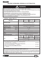
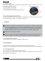
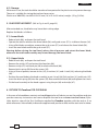
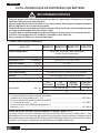
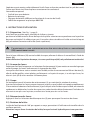
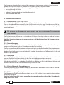
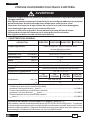
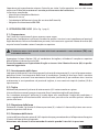
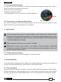
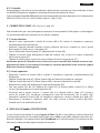
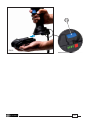
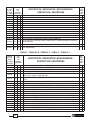
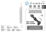
15 M 013
ENGLISH
FRANÇAIS
DEUTSCH
Certified Quality
Management System
Certified Environmental
Management System
Certified Occupational
Health & Safety
Management System
BATTERY OPERATED HYDRAULIC CUTTING TOOL
COUPE-CABLE HYDRAULIQUE SUR BATTERIE
HYDRAULISCHES AKKU-SCHNEIDWERKZEUG
HERRAMIENTA HIDRÁULICA DE CORTE A BATERíA
UTENSILE OLEODINAMICO DA TAGLIO A BATTERIA
B35M-TC025
B35M-TC025A
B35M-TC025E
B35M-TC025T
OPERATION AND MAINTENANCE MANUAL
NOTICE D'UTILISATION ET ENTRETIEN
BEDIENUNGSANLEITUNG
MANUAL DE USO Y MANTENIMIENTO
MANUALE D'USO E MANUTENZIONE
1
ESPAÑOL
ITALIANO
WARNING LABELS - ETIQUETTES SIGNALETIQUES - WARNSCHILDER ETIQUETAS DE ATENCION - ETICHETTE D'AVVERTENZA
Tool - Outil - Werkzeug - Herramienta - Utensile
– Before using the tool, carefully read the instructions in this manual.
– Avant d'utiliser cet outil, lire attentivement les instructions de cette notice.
– Vor Inbetriebnahme unbedingt die Bedienungsanleitung durchlesen.
– Antes de utilizar la herramienta, leer atentamente las instrucciones contenidas en este manual.
– Prima di utilizzare l'utensile, leggere attentamente le istruzioni contenute in questo manuale.
–
–
–
–
–
Keep hands clear of cutting blade.
Au cours du coupage, tenir les mains éloignées de la lame.
Während des Schneidvorganges die Hände vom Messer fernhalten.
Durante el corte, tener las manos alejadas de la cuchilla.
Durante il taglio, tenere le mani lontane dalla lama.
– See page 34.
– Voir page 34.
– siehe Seite 34.
– Vease página 34.
– Vedere pagina 34.
Battery - Batterie - Akku - Batería - Batteria
– Never throw batteries into fire or water.
– Jamais jeter les batteries dans le feu ou dans l'eau.
– Werfen Sie Akkus nicht in das Feuer oder Wasser.
– Nunca tire las baterías al fuego o al agua.
– Mai gettare le batterie nel fuoco o in acqua.
– Always recycle the batteries.
– Recycler toujours les batteries.
– Verbrauchte Akkus stets dem Recycling zuführen.
– Reutilizar siempre las baterías.
– Riciclare sempre le batterie.
– Do not discard batteries into domestic refuse or waste disposal.
– Ne pas jeter de batteries dans une poubelle ou autre lieu non prévu à cet effet.
– Verbrauchte Akkus der allgemeinen Abfallentsorgung zuführen
– No tirar las baterías al cubo de basura o lugar paracido.
– Non buttare le batterie fuori uso nei cestini della spazzatura o luoghi simili.
2
FIG. 1
26 - 46
LOWER AND UPPER BLADE
LAME INFÉRIEURE ET SUPÉRIEURE
UNTERES UND OBERES MESSER
CUCHILLA INFERIOR Y SUPERIOR
LAMA INFERIORE E SUPERIORE
66
LATCH
LOQUET
VERRIEGELUNG
ANCLAJE DE RETENCION
DENTE DI AGGANCIO
21
HEAD SUPPORT
SUPPORT TETE
KOPFHALTER
SOPORTE CABEZA
SUPPORTO TESTA
9
4
OPERATING BUTTON
BOUTON D'ACTIONNEMENT
STARTKNOPF
PULSADOR DE ACCIONAMIENTO
PULSANTE DI AZIONAMENTO
3
15
BATTERY
BATTERIE
AKKU
BATERIA
BATTERIA
BATTERY RELEASE
DEBLOCAGE BATTERIE
AKKU ENTRIEGELUNG
DESBLOQUEO BATÉRIA
SBLOCCO BATTERIA
2
3
PRESSURE RELEASE BUTTON
BOUTON DE DECOMPRESSION
DRUCKABLASSKNOPF
PULSADOR DE DESBLOQUEO PRESION
PULSANTE SBLOCCO PRESSIONE
RESIDUAL BATTERY ENERGY DISPLAY
INDICATEUR DE CHARGE DE BATTERIE
AKKUANZEIGE
INDICADOR DE CARGA DE LA BATERIA
INDICATORE DI CARICA DELLA BATTERIA
ENGLISH
BATTERY OPERATED HYDRAULIC CUTTING TOOL
WARNING
• Wear eye protection. Metal chips can fly from blades when cutting.
• Do not cut short, free pieces of steel rod or rope as they may fly off dangerously, causing
injury to the operator or persons nearby.
• Inspect the blades before each use. Do not use damaged blades.
• Damaged blades can break and cause injury or damage to the tool.
• Work in a clean, uncluttered area. Keep persons away from immediate work area.
• Use this cutting tool for the manufacturer’s intended purpose only.
• Do not cut live cables or conductors.
1. GENERAL CHARACTERISTICS
B35M-TC025 B35M-TC025E B35M-TC025T B35M-TC025A
TOOL TYPE:
Application range:
Rated operating pressure
Dimensions LxWxH
suitable for cutting steel ropes,
copper and aluminium conductors
450 (6,500)
bar (psi):
391 x 133 x 81 (15.4 x 5.2 x 3.2)
mm (inches):
Weight with battery
kg (lbs):
3,1 (6.8)
Motor
Volt DC:
18
Battery type CB1820L
AGIP ARNICA 22 or ESSO INVAROL EP22 or equivalent
the tool is equipped with a maximum pressure valve
Safety:
Operating temperature
-15 to +50 (+5 to +122)
°C (°F):
Battery charger ASC30-36
Input
18 / 2.0 Li-Ion
Volt / Ah:
Recommended oil:
UE
27044000
UK
27045000
AUS/NZ
27047000
USA/CAN
27046000
Volt / Hz:
220 - 240 / 50 - 60
115 / 60
W:
85
Acoustic Noise (Directive 2006/42/EC, annexe 1, point 1.7.4.2 letter u)
– The weighted continuous acoustic pressure level equivalent
A at the work place LpA is equal to .............................................................................................................. 64,9 dB (A)
– The maximum value of the weighted acoustic displacement
pressure C at the work place LpCPeak is equal to ........................................................................................ 99,7 dB (C)
– The acoustic power level emitted by the machine
LWA is equal to ...................................................................................................................................................... 69,3 dB (A)
Risks due to vibration (Directive 2006/42/EC, annexe 1, point 2.2.1.1)
Tests carried out in compliance with the indications contained in UNI ENV 25349 and UNI EN 28662 part
1st Standards, and under operating conditions much more severe than those normally found, certify that
the weighted root mean square in frequency of the acceleration the upper limbs are exposed to for
each biodynamic reference axis is 0,527 m/sec2 max.
4
ENGLISH
The tool can be held in one hand while positioning the conductor with the other.
The part reference includes the following:
– Basic tool complete with battery.
– Spare battery.
– Battery charger (model depends on the tool version).
– Plastic carrying case VAL P22.
2. INSTRUCTIONS FOR USE (Ref. to Fig. 1 page 3)
2.1) Setting
With the tool in the rest position, proceed as follows:
Insert the conductor between the blades at the desired cutting point.
For a running conductor, release the latch (66) and open the tool head.
OPENING THE UPPER BLADE MUST BE DONE ONLY WHEN THE TOOL IS IN REST POSITION (LOWER
BLADE (26) COMPLETELY RETRACTED).
With the conductor on the lower blade (26), close the tool head and fully secure the latch (66).
Before commencing the cutting operation ensure that the latch (66) is fully secured: partial
closure may damage the tool head.
2.2) Blade advancement
Grip the tool firmly and comfortably and press the operating button (4) to activate the motor-pump
group for the advancement of the lower blade (26). To halt the advancement, release the operating
button (4) and the motor will cut out.
2.3) Cutting
By keeping operating button (4) pressed, the motor continues to operate: the ram will gradually
move the lower blade to cut through the conductor.
The motor will continue to operate after the maximum pressure relief valve has activated. No further
cutting force is applied, the oil is bypassed and returned to the reservoir.
2.4) Blade retraction
Press the pressure release button (9), the ram will retract and open the blades.
2.5) Head rotation
For ease of operation the tool head can rotate through 180°, allowing the operator to work in the
most comfortable position.
Warning: do not attempt to rotate the head when the hydraulic circuit is pressurised.
5
ENGLISH
2.7) Battery status
The battery is equipped with LED indicators that indicate the remaining battery life at any time by
pressing the adjacent button (P).
4 LEDs illuminated: Fully charged
2 LEDs illuminated: 50 % capacity
1 LED flashing: Minimum charge, replace the battery
2
P
2.8) Insertion/replacement of battery
To replace the battery, remove it by pressing the release button (15) (Ref. to Fig.2 page 24), then
insert the new battery, sliding it into the guides until it locks.
3. WARNING
THE
TOOL IS UNSUITABLE FOR CONTINUOUS USE AND SHOULD BE ALLOWED TO COOL DOWN
FOLLOWING UNINTERRUPTED, SUCCESSIVE CUTTING OPERATIONS; FOR INSTANCE, HAVING EXHAUSTED
A FULLY CHARGED BATTERY IN ONE SESSION, DELAY BATTERY REPLACEMENT FOR A FEW MINUTES.
OBSERVE RECOMMENDED REST PERIODS ALSO WHEN USING AN EXTERNAL POWER SUPPLY.
DO NOT USE THIS TOOL ON LIVE CABLES.
PROTECT THE TOOL FROM RAIN AND MOISTURE. WATER WILL DAMAGE THE TOOL AND BATTERY.
ELECTRO-HYDRAULIC TOOLS SHOULD NOT BE OPERATED IN POURING RAIN OR UNDER WATER.
3.1) Using the battery charger
Carefully follow the instructions in the battery charger manual.
4. MAINTENANCE
The tool is robust, completely sealed, and requires very little daily maintenance.
Compliance with the following points should help to maintain the optimum performance of the tool:
4.1) Thorough cleaning
Dust, sand and dirt are a danger for any hydraulic device.
Every day, after use, the tool must be wiped with a clean cloth taking care to remove any residue,
especially close to moveable parts.
6
ENGLISH
4.2) Storage
When not in use, the tool should be stored and transported in the plastic case to prevent damage.
The case is suitable for storing the tool and accessories.
Plastic case: VAL P22, size 465x315x135 mm (18.3x12.4x5.3 inches) weighs 1,5 kg (3.3 lbs).
5. BLADE REPLACEMENT (Ref. to Fig. 4 and 5, page 33)
After extended use, the blades may loose their cutting edge.
Replace the blades as follows:
5.1) Lower blade
– Release latch (66), and open the tool head.
– Operate the tool to advance the lower blade (26) until grub screw (27) is visible on theram (16).
– Using a flat blade screwdriver remove the grub screw (27) and release the lower blade (26).
– Insert the new blade and fit the grub screw (27).
Warning: before closing the tool head, release the oil pressure and retract the lower blade,
otherwise the tool head assembly may hit and damage, the lower blade.
5.2) Upper blade
– Release latch (66), and open the tool head.
– Remove the circlip (87) and extract the head pin (86).
– Remove circlip (47) and latch pin (40) to release the latch (66).
Remove latch spring (50) from the spacer (39).
– Using a 10 mm spanner, remove 8 nuts (42), 8 washers (41) and 4 studs (48), releasing the blade
(46).
– Position the new blade in the head assembly, insert 4 studs (48), fit 8 washers (41) and 8 nuts (42).
Insert the latch spring (50) into the spacer (39). Reassemble the latch (66) and tighten the 8 nuts.
– Fit the head assembly to the head support using the pin (86) and circlip (87).
6. RETURN TO Cembre FOR OVERHAUL
In the case of a breakdown contact our Local Agent who will advise you on the problem and give
you the necessary instructions on how to dispatch the tool to our nearest service Centre; if possible, attach a copy of the Test Certificate supplied by Cembre together with the tool or, if no
other references are available, indicate the approximate purchase date and the tool serial number.
7
FRANÇAIS
OUTIL HYDRAULIQUE DE SERTISSAGE SUR BATTERIE
RECOMMANDATIONS
• Toujours porter une visière de protection pendant les opérations de coupe, car de petits
éclats de câbles peuvent être propulsés.
• Ne pas couper de morceaux trop courts, car ils pourraient être projetés dangereusement et
blesser l’opérateur ou une personne proche.
• Contrôler les lames avant chaque utilisation. Ne pas utiliser l’outil avec une lame endommagée.
• Les lames endommagées peuvent abîmer l’outil.
• Travailler dans un espace propre et ordonné. Eloigner les personnes de la zone de travail.
• N’utiliser cet outil que dans les conditions indiquées par le fabricant.
• Ne pas couper de câble sous tension électrique.
1. CARACTERISTIQUES GENERALES
B35M-TFC B35M-TFCE B35M-TFCT B35M-TFCA
OUTIL TYPE:
conçu pour couper des câbles métalliques
en acier, cuivre ou aluminium.
Domaine d'application:
450 (6,500)
Pression nominale
bar (psi):
Dimensions LxLxH
mm (inches):
Poids avec batterie
kg (lbs):
3,1 (6.8)
Volt DC:
Volt / Ah:
18 / 2.0 Li-Ion
Moteur
Batterie type CB1820L
Huile recommandée:
391 x 133 x 81 (15.4 x 5.2 x 3.2)
18
AGIP ARNICA 22 ou ESSO INVAROL EP22 ou équivalents
l’outil est équipé d'une valve de surpression
Sécurité:
-15 à +50 (+5 à +122)
Température de fonctionnement °C (°F):
Chargeur de batterie ASC30-36
Alimentation
UE
27044000
UK
27045000
AUS/NZ
27047000
USA/CAN
27046000
Volt / Hz:
220 - 240 / 50 - 60
115 / 60
85
Pression sonore aérienne (Directive 2006/42/CE, annexe 1, point 1.7.4.2, lettre u)
– Le niveau de pression sonore continue équivalente
pondérée A sur le poste de travail LpA est .................................................................................................. 64,9 dB (A)
– Le niveau de pression sonore instantanée pondéré
C sur le poste de travail LpCPeak est .................................................................................................................. 99,7 dB (C)
– Le niveau de puissance acoustique dégagée par la
machine LWA est .................................................................................................................................................... 69,3 dB (A)
W:
Risques dérivés des vibrations (Directive 2006/42/CE, annexe 1, point 2.2.1.1)
Des relevés réalisés suivant les indications des Normes UNI ENV 25349 et UNI EN 28662 partie 1a, dans
des conditions de service largement représentatives des conditions d’emploi normales témoignent que la
valeur quadratique moyenne pondérée en fréquence de l’accélération à laquelle sont exposés les membres
supérieurs pour chaque axe biodynamique de référence est de 0,527 m/sec2 maxi.
8
FRANÇAIS
L’opérateur peut manier confortablement l’outil d’une seule main pendant tout le cycle de travail;
l’autre main étant ainsi libre de placer correctement le conducteur.
L’ensemble comprend:
– Outil de base avec batterie.
– Batterie de rechange.
– Chargeur de batterie (différent en fonction de la version de l’outil).
– Coffret de rangement en plastique VAL P22.
2. INSTRUCTIONS D’UTILISATION
2.1) Préparation (Voir Fig. 1, page 3)
Avec l’outil en position repos, procéder de la façon suivante:
positionner le câble entre les lames de façon à ce qu’elles soient en correspondance avec la position
de coupe souhaitée. Si le câble est passant, il sera alors nécessaire d’ouvrir la tête en tirant le loquet
(66) permettant l’ouverture de la tête (lame supérieure).
L’OUVERTURE DE LA LAME SUPÉRIEURE NE DEVRA ÊTRE EFFECTUÉE QU’AVEC LA LAME INFÉRIEURE
(26) COMPLÈTEMENT BAISSÉE.
Poser la lame inférieure (26) contre le câble à couper, refermer la tête en la verrouillant à l’aide du
loquet (66).
Avant d’effectuer l’opération de coupe, s’assurer que le loquet (66) soit parfaitement enclenché.
2.2) Avance des lames
Empoigner fort l’outil et appuyer sur le bouton d’actionnement (4) pour mettre en marche le groupe
moteur pompe; les lames commencent à s’approcher du câble.
Lorsque les deux lames sont en contact avec le câble, arrêter le mouvement en lâchant bouton (4),
afin de vérifier qu’elles soient placées parfaitement sur le point à couper; si ce n’est pas le cas, les
réouvrir (voir § 2.4) et les remettre à la bonne place.
2.3) Coupe
En maintenant pressé le bouton de actionnement (4), on maintient la rotation du moteur;
le piston fait avancer les lames progressivement jusqu’à ce que le câble soit coupé complètement.
Si on maintient le bouton d’actionnement (4) pressé après avoir fini de couper le câble, on entendra
rapidement se déclencher la valve de surpression; cette dernière dévie directement l’huile dans le
réservoir et non plus vers le piston, annulant ainsi toute pression sur les lames.
2.4) Réouverture des lames
Appuyer à fond sur le bouton de décompression (9) pour provoquer l’ouverture des lames.
2.5) Rotation de la tête
La tête de l’outil pivote de 180° par rapport au corps, permettant à l’utilisateur de travailler dans la
meilleure position.
Attention: ne pas forcer la rotation de la tête, lorsque le circuit hydraulique est sous pression.
9
FRANÇAIS
2.7) Autonomie de la batterie
La batterie est équipée d’indicateurs à LED qui permettent de contrôler, à tout moment, son autonomie résiduelle en appuyant sur la touche (P).
4 led allumées: autonomie maximale
2 led allumées: autonomie à 50 %
1 led clignotante: autonomie minimale, remplacer la batterie.
2
P
2.8) Introduction/replacement de la batterie
Pour remplacer la batterie, la retirer en appuyant sur le mécanisme de déblocage (15) (Voir Fig. 2,
page 24), puis introduire la nouvelle batterie en la faisant coulisser sur les guides jusqu’au blocage
complet.
3. PRECAUTIONS
L’OUTIL N’EST PAS CONÇU POUR UNE UTILISATION EN CONTINU; APRÈS AVOIR EFFECTUÉ UNE QUANTITÉ
D'OPÉRATIONS DE COUPE CONSÉCUTIVES À PARTIR D’UNE BATTERIE COMPLÈTEMENT CHARGÉE, AU
MOMENT DU REMPLACEMENT DE LA BATTERIE, NOUS SUGGÉRONS D’OBSERVER UNE PÉRIODE D’ARRÊT
POUR PERMETTRE LE REFROIDISSEMENT DE L’OUTIL.
NE PAS UTILISER L'OUTIL SUR DES CONDUCTEURS SOUS TENSION.
PROTÉGER L’OUTIL DE LA PLUIE ET DE L’HUMIDITÉ. L’EAU POURRAIT ENDOMMAGER L’OUTIL ET LA
BATTERIE LES OUTILS HYDRO-ELECTRIQUES NE DEVRAIENT PAS ÊTRE UTILISÉS SOUS LA PLUIE ET SOUS
L’EAU.
3.1) Utilisation du chargeur de batterie
Suivre attentivement les instructions indiquées sur le manuel.
4. ENTRETIEN
Cet outil est robuste,complètement scellé et ne nécessite aucune préoccupation ou entretien particulier. Les recommandations qui suivent sont néanmoins souhaitables pour assurer une longévité
optimum:
4.1) Nettoyage élémentaire
Veiller à protéger l’outil de la poussière, du sable et de la boue qui sont un danger à tout système
hydraulique. Chaque jour après utilisation, l’outil doit être nettoyé à l’aide d’un chiffon propre, tout
particulièrement aux endroits de pièces mobiles.
10
FRANÇAIS
4.2) Rangement
Au repos, pour protéger l'outil des coups accidentels et de la poussière, il convient de le ranger dans
le coffret. Ce coffret (type VAL P22) a comme dimensions 465x315x135 mm (18.3x12.4x5.3 inches)
et un poids de 1,5 kg (3.3 lbs.), est adapté pour contenir l'outil et ses accessoires.
5. CHANGEMENT DES LAMES (Voir Fig. 4 et 5 page 33)
Il peut arriver qu’ une utilisation prolongée ou non appropriée cause la perte d’affûtage des lames
ou leur endommagement. Le changement des lames est cependant très simple.
5.1) Lame inférieure
– Déverrouiller le loquet (66) et ouvrir la tête, jusqu’à la butée.
– Actionner l’outil pour faire avancer la lame inférieure jusqu’à ce que soit visible sa vis de fixation
(27) sur le piston (16).
– A l’aide d’un tournevis, dévisser la vis (27) de façon à libérer la lame (26).
– Enlever la vieille lame, introduire la lame neuve et la bloquer au moyen de la même vis (27).
Attention: avant de refermer la lame supérieure, relâcher la pression d’huile, de façon à ce que
la lame inférieure redescende complètement, pour éviter qu’elle soit heurtée et endommagée
par la supérieure.
5.2) Lame supérieure
– Déverrouiller le loquet (66) et ouvrir la tête, jusqu’à la butée.
– Enlever l’anneau élastique (87), extraire l’axe (86) pour libérer le groupe supérieur.
– Enlever l’anneau élastique (47), extraire l’axe (40) et dégager le loquet (66).
Récupérer le ressort (50), qui sera ainsi libéré du logement dans l’entretoise (39).
– A l’aide d’une clé de “10”, enlever les 8 écrous (42) et les rondelles (41), extraire les goujons (48)
de façon à libérer la lame (46).
– La remplacer par la neuve, replacer les 4 goujons, les rondelles (41) et serrer manuellement les 8
écrous (42); introduire le ressort (50) dans le logement correspondant de l’entretoise (39), remonter
le loquet sur le groupe supérieur, serrer les 8 écrous à fond.
– Placer le groupe supérieur dans son logement, introduire à fond l’axe (86) et le bloquer à l’aide
de son anneau élastique (87).
6. ENVOI EN REVISION A Cembre
En cas de dysfonctionnement de l’appareil, merci de vous adresser à notre Agent Régional qui
vous conseillera et le cas échéant vous donnera les instructions nécessaires pour envoyer l’outil à
notre Centre de Service le plus proche. Dans ce cas, joindre une copie du Certificat d’Essai livré par
Cembre avec l’outil ou, à défaut d’autres éléments de référence, indiquer la date d’achat approximative et numéro de série.
11
DEUTSCH
HYDRAULISCHES AKKU-SCHNEIDWERKZEUG
ACHTUNG
• Tragen Sie immer eine Schutzbrille, da sich beim Schneiden Metallsplitter lösen können.
• Nicht zu kurze Stangen und Stahlseile schneiden, da diese kleinen Stücke den Bediener oder
andere in der Nähe befindliche Personen verletzen können.
• Überprüfen Sie die Schneidmesser vor jedem Gebrauch. Verwenden Sie nie ein Werkzeug mit
beschädigten Schneidmessern. Defekte Schneidmesser könnten dasWerkzeug stark beschädigen.
• Den Arbeitsbereich immer sauber halten und es sollten sich keine weitere Menschen im
Arbeitsbereich aufhalten.
• Das Werkzeug nur für die vom Hersteller angegebenen Zwecke verwenden.
• Es dürfen keine unter Spannung stehenden Teile geschnitten werden.
1. ALLGEMEINE EIGENSCHAFTEN
B35M-TC025 B35M-TC025E B35M-TC025T B35M-TC025A
WERKZEUG TYP:
Geeignet zum Schneiden von Kupfer-,
Anwendungsbereich:
Aluminiumkabeln und Stahlseilen
Arbeitsdruck
Abmessungen LxBxH
450 (6,500)
bar (psi):
391 x 133 x 81 (15.4 x 5.2 x 3.2)
mm (inches):
3,1 (6.8)
Gewicht inkl. Akku
kg (lbs):
Motor
Volt DC:
18
Volt / Ah:
18 / 2.0 Li-Ion
Akku Typ CB1820L
Empfohlenes Öl:
AGIP ARNICA 22 oder ESSO INVAROL EP22 oder ähnliches
Sicherheit:
Das Werkzeug ist mit einem Überdruckventil ausgestattet
Betriebstemperatur
Eingangspannung
-15 bis +50 (+5 bis +122)
°C (°F):
Akkuladegerät ASC30-36
UE
27044000
Volt / Hz:
W:
UK
27045000
220 - 240 / 50 - 60
85
AUS/NZ
27047000
USA/CAN
27046000
115 / 60
Lärmschutzbestimmung (Richtlinie 2006/42/EG, Anhang 1, Nummer 1.7.4.2, Buchstabe u)
– Der konstante Lärmpegel entsprechend
Gewichtung A am Arbeitsplatz LpA entspricht ......................................................................................... 64,9 dB (A)
– Der höchste Lärmpegel entsprechend
Gewichtung C am Arbeitsplatz LpCPeak entspricht .................................................................................... 99,7 dB (C)
– Die Lärmbelastung des Geräts
LWA entspricht ....................................................................................................................................................... 69,3 dB (A)
Risiken aufgrund von Vibrationen (Richtlinie 2006/42/EG, Anhang 1, Nummer 2.2.1.1)
Messungen entsprechend der Normen UNI ENV 25349 und UNI EN 28662 Teil 1, unter repräsentativen
Bedingungen haben gezeigt, daß der durchschnittliche Meßwert an den oberen Teilen, die den Vibrationen
ausgesetzt sind, an den jeweiligen Achsen ist den Wert höchstens von 0,527 m/sek2.
12
DEUTSCH
Der Anwender kann das Gerät während des gesamten Arbeitsganges mit einer Hand bedienen.
Mit der anderen Hand kann das Kabel in der korrekten Position gehalten werden.
Zum Lieferumfang unter dieser Bezeichnung gehören folgende Teile:
– Basisausführung inkl. Akku.
– Ersatzakku.
– Ladegerät (entsprechend der Länderkonfiguration).
– Kunststoffkoffer VAL P22.
2. BEDIENUNGSHINWEISE
2.1) Vorbereitung (Siehe Bild 1 Seite 3)
Wenn das Werkzeug in Ruhestellung ist, sind folgende Schritte notwendig:
Das zu schneidende Seil am gewünschten Schnittpunkt zwischen den Schneidmessern (26) positionieren. Bei durchgehendem Seil wird das Gegenmesser durch Öffnen der Verriegelung (66)
zurückgeklappt.
DIE ÖFFNUNG DES GEGENMESSERS DARF NUR MIT GANZ ZURÜCKGEFAHRENEM SCHNEIDMESSER
(26) ERFOLGEN.
Das Schneidmesser (26) um das zu schneidende Seil legen. Den Kopf schliessen und die Verriegelung (66) einrasten lassen.
Vor dem Schneiden hat man sich zu vergewissern, daß die Verriegelung (66) einwandfrei eingerastet ist.
2.2) Schneidvorgang
Das Werkzeug fest in die Hand nehmen und durch Drücken des Startknopfes (4) wird der Pumpenmotor gestartet, wobei sich das Schneidmesser dem Seil annähert.
Das Zusammenfahren der Schneidmesser kann durch Loslassen des Startknopfes (4) gestoppt werden.
Auf diese Weise kann kontrolliert werden, dass sich die Schneidmesser genau auf dem zu schneidenden Punkt befinden. Ist dies nicht der Fall, sind die Schneidmesser zu öffnen (siehe § 2.4) und
erneut zu positionieren.
2.3) Schneiden
Wenn der Startknopf (4) gedrückt gehalten wird, läuft der Motor weiter: der Kolben lässt das Schneidmesser allmählich nach vorn fahren, bis das Seil vollständig geschnitten worden ist.
Wird der Startknopf (4) auch nach Beendigung des Seilschnitts gedrückt gehalten, spricht das
Überdruckventil sofort an, wobei das Öl direkt in den Behälter anstatt in den Kolben gelangt und
ein weiterer Druck auf die Schneidmesser ausgeschlossen wird.
2.4) Zurückfahren des Schneidmessers
Drücken Sie kräftig den Druckablassknopf (9), dadurch fährt der Kolben zurück und das Schneidmesser gibt das Kabel frei.
2.5) Drehbewegung des Kopfes
Das Werkzeug ist mit einem Kopf ausgerüstet, der um 180° drehbar ist und somit ein komfortables
Arbeiten ermöglicht.
Der Kopf sollte keinesfalls in eine andere Position gedreht werden, während das Schneidwerkzeug unter Druck steht.
13
DEUTSCH
2.7) Akkuladung
Die Akku ist mit LED-Anzeigen ausgestattet, die jederzeit über die verbleibende Akkulaufzeit Auskunft gibt, indem man auf die Taste (P) drückt.
4 LED eingeschaltet: Maximale Ladung
2 LED eingeschaltet: Ladung zu 50 %
1 LED blinkend: Minimale Ladung,
Akku austauschen bzw. aufladen
2
P
2.8) Akku Einsetzen/Auswechseln
Drücken Sie für den Akkuaustausch auf die Entriegelung (15) (siehe Bild 2, Seite 24) und führen Sie
den neuen Akku bis zum Einratsen ein.
3. HINWEISE
DIE AKKUWERKZEUGE SIND NICHT FÜR EINEN DAUEREINSATZ GEEIGNET. WENN EIN VOLL GELADENER
AKKU DURCH HINTEREINANDER AUSGEFÜHRTE SCHNITTE GETAUSCHT WERDEN MUSS, EMPFEHLEN
WIR VOR DEM AKKUWECHSEL DAS WERKZEUG EINE ANGEMESSENE ZEIT ABKÜHLEN ZU LASSEN.
DAS WERKZEUG DARF NICHT BEI UNTER SPANNUNG STEHENDEN LEITERN VERWENDET WERDEN.
DAS WERKZEUG VOR REGEN UND FEUCHTIGKEIT SCHÜTZEN. WASSER KÖNNTE DAS WERKZEUG
UND DEN AKKU BESCHÄDIGEN. ELEKTROHYDRAULISCHE WERKZEUGE SOLLTEN NICHT IM REGEN
ODER UNTER FLIESSENDEM WASSER EINGESETZT WERDEN.
3.1) Verwendung des Ladegerätes
Die in der Bedienungsanleitung gegebenen Hinweise sind zu beachten.
4. WARTUNG
Das Werkzeug ist robust und benötigt keine spezielle Pflege oder Instandhaltung.
Zur Erhaltung der Garantieansprüche beachten Sie folgende Hinweise:
4.1) Pflege
Dieses Werkzeug sollte vor starker Verschmutzung geschützt werden, da dies für ein hydraulisches
System gefährlich ist. Jeden Tag nach der Arbeit sollte das Werkzeug mit einem Tuch von Schmutz
und Staub gereinigt werden, besonders die beweglichen Teile.
14
DEUTSCH
4.2) Lagerung
Wenn das Werkzeug nicht benötigt wird, sollte es in der Kunststoffkassette gelagert werden und
ist somit gegen Beschädigungen wie Stoß und Staub geschützt.
Die Kunststoffkassette Typ VAL P22 hat folgende Abmessungen: 465x315x135 mm (18.3x12.4x5.3
inches) und ein Gewicht von 1,5 kg (3.3 lbs.), geeignet zum Lagern von Werkzeug und Zubehör.
5. SCHNEIDMESSER WECHSELN (Siehe Bild 4 und 5, Seite 33)
Nach längerem Gebrauch oder nach Anwendungsfehlern kann es zu Abnutzungen (beschädigt, unscharf ) an den Messern kommen. Bei einem Wechsel sollten Sie wie folgt vorgehen:
5.1) Schneidmesser
– Den Kopf durch Betätigung der Verriegelung (66) öffnen.
– Den Motor betätigen und das Schneidmesser nach vorne fahren, bis die Stiftschraube (27) zur
Befestigung des Messers (26) auf dem Kolben (16) sichtbar ist.
– Die Stiftschraube (27) mit einem Schraubenzieher herausschrauben und das Schneidmesser (26)
auswechseln.
– Anschließend mit der Stiftschraube (27) das neue Messer wieder befestigen.
Achtung: bevor das Gegenmesser wieder geschlossen wird, muss das Schneidmesser komplett
zurückgefahren sein, sonst könnten sich die o.g. Schneidmesser gegenseitig beschädigen.
5.2) Gegenmesser
– Den Kopf durch Betätigung der Verriegelung (66) öffnen.
– Den Federring (87) entfernen und den Bolzen (86) soweit herausziehen, dass der obere Teil des
Schneidkopfes abgenommen werden kann.
– Den Federring (47) und Bolzen (40) demontieren, dabei wird die Verriegelung auch entfernt. Die
Feder (50) aus ihrem Sitz im Abstandsstück (39) demontieren.
– Die 8 Muttern (42) mit einem “10”-Schlüssel lösen, die Zugbolzen (48) und Scheiben (41) herausziehen und das Gegenmesser (46) demontieren.
– Das Gegenmesser durch ein neues ersetzen. Anschließend die 4 Zugbolzen mit den Muttern (42)
leicht anziehen. Die Feder (50) in ihren Sitz mit der Verriegelung montieren und die Muttern mit
den Scheiben (41) fest anziehen.
– Die obere Gruppe auf dem Schneidkopf mit dem Bolzen (86) und Federring (87) montieren.
6. EINSCHICKEN AN Cembre ZUR ÜBERPRÜFUNG
Sollten an dem Gerät Fehler auftreten, wenden Sie sich bitte an unsere Gebietsvertretung, die
Sie gerne beraten und Ihnen alle nötigen Informationen zum Einsenden des Gerätes an unseren
Hauptsitz geben wird. Wenn vorhanden, legen Sie dem Gerät bitte eine Kopie des von Cembre
mitgelieferten Zertifikates bei. Bei fehlenden Informationen geben Sie bitte an, wann Sie das Gerät
erworben haben.
15
ESPAÑOL
HERRAMIENTA HIDRAULICA DE CORTE A BATERíA
ATENCION
• Operar siempre con las gafas de trabajo, durante las operaciones de corte pueden ocasionarse
esquirlas metálicas.
• No cortar trozos demasiado cortos de cables de acero, que pudieran ser proyectados peligrosamente a distancia, causando daños al operador y a las personas cercanas.
• Inspeccionar las cuchillas antes de utilizar la herramienta. No utilizar la herramienta con las
cuchillas dañadas.
• Cuchillas dañadas pueden causar la rotura de la herramienta.
• Operar en área de trabajo limpia, despejada y alejadas de las personas.
• Sólo utilizar esta harramienta de corte para el fin previsto por el constructor.
• No cortar conductores o cables con tensión eléctrica.
1. CARACTERíSTICAS GENERALES
B35M-TC025 B35M-TC025E B35M-TC025T B35M-TC025A
HERRAMIENTA TIPO:
Campo de aplicación:
idónea para cortar cables de cobre,
aluminio y acero
Presión nominal de trabajo
Dimensiones LxAxA
bar (psi):
450 (6,500)
mm (inches):
391 x 133 x 81 (15.4 x 5.2 x 3.2)
Peso con batería
kg (lbs):
Motor
Volt DC:
18
Volt / Ah:
18 / 2.0 Li-Ion
Batería tipo CB1820L
Aceite recomendado:
3,1 (6.8)
AGIP ARNICA 22 o ESSO INVAROL EP22 o equivalentes
Seguridad:
la herramienta está provista de válvula de sobrepresión
Temperatura de funcionamiento °C (°F):
Cargador de batería ASC30-36
-15 a +50 (+5 a +122)
UE
27044000
UK
27045000
AUS/NZ
27047000
USA/CAN
27046000
220 - 240 / 50 - 60
115 / 60
85
W:
Nivel sonoro aéreo (Directiva 2006/42/CE, anexo 1, punto 1.7.4.2, letra u)
– El nivel de presión acústica contínua equivalente
ponderado A en el puesto de trabajo LpA es de ...................................................................................... 64,9 dB (A)
– El nivel máximo de la presión acústica instantánea
ponderada C en el puesto de trabajo LpCPeak es de ................................................................................. 99,7 dB (C)
– El nivel de potencia acústica emitida por la máquina
LWA es de ................................................................................................................................................................ 69,3 dB (A)
Alimentación
Volt / Hz:
Riesgos debidos a las vibraciones (Directiva 2006/42/CE, anexo 1, punto 2.2.1.1)
Medidas realizadas según las indicaciones de las Normas UNI ENV 25349 y UNI EN 28662 parte 1a, en
condiciones de utilización ampliamente representativas respecto a las que se encuentran normalmente,
atestan que el valor cuadrático medio ponderado en frecuencia, de la aceleración a la que están expuestos
los miembros superiores para cada eje biodinámico de referencia, es al máximo de 0,527 m/sec2.
16
ESPAÑOL
El operario puede manejar cómodamente la herramienta durante todo el ciclo de trabajo con una
sola mano mientras que con la otra mantiene el conductor en su posición correcta.
La sigla identifica el conjunto formado por:
– Herramienta base con batería.
– Batería de reserva.
– Cargador de batería (diferente según el modelo de la herramienta).
– Caja de almacenamiento tipo VAL P22.
2. INSTRUCCIONES DE USO
2.1) Preparación (Ref. a Fig. 1 pag. 3)
Con la herramienta en posición de reposo, opere como sigue:
colocar el cable entre las cuchillas de manera que éstas se encuentren en el punto de corte deseado.
Si el cable es pasante, será necesario abrir la cabeza, desenganchando el anclaje de retención (66)
y hacer girar el conjunto superior.
SOLAMENTE
SE PUEDE ABRIR LA CUCHILLA SUPERIOR CUANDO LA CUCHILLA INFERIOR
ENCUENTRE COMPLETAMENTE RETRAÍDA.
(26)
SE
Colocar la cuchilla inferior (26) sobre el cable a cortar, volver a cerrar el grupo superior bloqueándolo
con el anclaje de retención (66).
Antes de proceder con la operación de corte, comprobar que el anclaje de retención (66) esté
enganchado perfectamente.
2.2) Acercamiento de las cuchillas
Empuñar firmemente la herramienta y apretar el pulsador de accionamiento (4): se pone en marcha
el grupo motor-bomba y la cuchilla empieza a acercarse al cable. Cuando las dos cuchillas están en
contacto con el cable, detener el movimiento de las mismas soltando el pulsador (4) para comprobar
que se encuentran exactamente en la posición del punto que se desea cortar; de no ser así, volver
a abrirlas (véase el punto 2.4) y volver a situarlas.
2.3) Corte
Manteniendo apretado el pulsador de accionamiento (4), el pistón hará avanzar progresivamente
la cuchilla inferior hasta cortar completamente el cable.
Si se mantuviera apretado el pulsador (4) después de finalizar el corte del cable, se activaría rápidamente la válvula de sobrepresión, desviando el aceite directamente al tanque y no al pistón,
anulando cualquier otra impulsión sobre las cuchillas.
2.4) Reapertura de las cuchillas
Apretando a fondo el pulsador de desbloqueo de la presión (9) se obtendrá el retorno del pistón
con la consiguiente apertura de las cuchillas.
2.5) Rotación de la cabeza
La cabeza de la herramienta puede rotar hasta 180° respecto al cuerpo, permitiendo al operario
realizar el trabajo en la posición más adecuada.
Atencion: no fuerce la cabeza, intentando rotarla, mientras el circuito hidráulico esté presurizado.
17
ESPAÑOL
2.7) Autonomía de la batería
La batería está provista de indicadores de led que permiten saber la autonomía restante en cualquier
momento pulsando el botón (P).
4 led encendidos: autonomía máxima
2 led encendidos: autonomía al 50 %
1 led parpadeante: autonomía mínima, reemplazar la batería
2
P
2.8) Inserción/sustitución de la batería
Para sustituir la batería, retírela pulsando el desbloqueo (15) (Ref. a Fig. 2, pag. 24) y luego inserte
la nueva batería deslizándola por las guías hasta su tope.
3. ADVERTENCIAS
LA HERRAMIENTA NO ESTA PREPARADA PARA UN EMPLEO CONTINUO; UNA VEZ EJECUTADO EL NUMERO
DE OPERACIONES MÁXIMO PERMITIDO POR UNA BATERÍA, A LA HORA DE CAMBIARLA, ACONSEJAMOS
UN OPORTUNO PERÍODO DE PAUSA PARA PERMITIR EL ENFRIAMIENTO DEL LA HERRAMIENTA.
NO UTILIZAR LA HERRAMIENTA SOBRE CONDUCTORES EN TENSION.
PROTEGER LA HERRAMIENTA DE LA LLUVIA Y LA HUMEDAD. EL AGUA PODRÍA DAÑAR LA HERRAMIENTA
Y LA BATERÍA. LAS HERRAMIENTAS ELECTROHIDRÁULICAS NO DEBERÍAN FUNCIONAR BAJO LA LLUVIA
O DEBAJO DEL AGUA.
3.1) Utilización del cargador de batería
Seguir atentamente las instrucciones detalladas en el manual correspondiente.
4. MANTENIMIENTO
Esta herramienta es robusta, completamente precintada y no requiere cuidados especiales para
obtener un funcionamiento correcto, bastará tener algunas precauciones sencillas:
4.1) Limpieza adecuada
Tenga presente que el polvo, la arena y la suciedad en general, representan un peligro para toda
herramienta hidráulica. Tras cada día de uso, se debe limpiar la herramienta con un trapo limpio,
teniendo cuidado de eliminar la suciedad depositada, especialmente junto a las partes móviles.
18
ESPAÑOL
4.2) Almacenamiento
Para proteger la herramienta de golpes accidentales y del polvo cuando no se va a utilizar,es conveniente guardarla cerrada en su estuche de plástico de cierre hermético.
Dicho estuche tipo VAL P22 de dimensiones 465x315x135 mm (18.3x12.4x5.3 inches) pesa 1,5 kg
(3.3 lbs.). Es apropiado para almacenar la herramienta y los accesorios.
5. CAMBIO DE LAS CUCHILLAS (Ref. a Fig. 4 y 5 pag. 33)
Puede suceder que las cuchillas se estropeen tras un uso prolongado o impropio.
Para efectuar el cambio de las cuchillas, actue como sigue:
5.1) Cuchilla inferior
– Abrir la cabeza desenganchando el anclaje de retención (66) y hacer girar completamente el
conjunto superior hasta el tope.
– Accionar el motor haciendo avanzar la cuchilla inferior (26) hasta que quede visible el tornillo de
sujeción (27) de la misma sobre el pistón (16).
– Con un destornillador, desenroscar el tornillo (27) y soltar así la cuchilla (26).
– Sacar la cuchilla vieja, colocar la nueva y sujetarla con el tornillo mencionado.
Atención: antes de volver a cerrar el conjunto superior, evacuar la presión del aceite, haciendo
retroceder completamente la cuchilla; en caso contrario, el conjunto superior podría chocar
contra la arista de la cuchilla inferior y estropearla.
5.2) Cuchilla superior
– Abrir la cabeza desenganchando el anclaje de retención (66) y hacer girar completamente el
conjunto superior hasta el tope.
– Quitar el aro (87), extraer el pasador (86) para soltar completamente el conjunto superior.
– Quitar el aro (47), extraer el pasador (40) y separar el anclaje de retención (66). Recuperar el muelle
(50), que quedará así liberado de su alojamiento en el distanciador (39).
– Con una llave de cubo del “10”, quitar las 8 tuercas (42) y extraer las arandelas (41) y los espárragos
(48) de manera que la cuchilla (46) quede suelta.
– Reemplazarla con la nueva, colocar los 4 espárragos, las arandelas (41) y apretar a mano las 8
tuercas (42); insertar el muelle (50) en su alojamiento del distanciador (39), volver a montar el
anclaje de retención sobre el conjunto superior, apretar a fondo las 8 tuercas (42).
– Colocar el grupo superior, insertar a fondo el pasador (86) y sujetarlo con el aro (87)
6. DEVOLUCION A Cembre PARA REVISIONES
En caso de fallo de la herramienta, contactar con nuestro Agente de Zona quien les aconsejará y
eventualmente les facilitará las instrucciones necesarias para remitir la herramienta a nuestro centro
de servicio más cercano. En tal caso, adjuntar a ser posible una copia del Certificado de Ensayo
entregado en su día por Cembre con la herramienta, o a falta de otro elemento de referencia,
indicar la fecha de compra aproximada y el número de serie.
19
ITALIANO
UTENSILE OLEODINAMICO DA TAGLIO A BATTERIA
AVVERTENZE
• Indossare sempre una visiera protettiva, durante le operazioni di taglio possono prodursi
schegge metalliche.
• Non tagliare spezzoni troppo corti di tondi o funi in acciaio che potrebbero essere proiettati
pericolosamente a distanza causando danni all’operatore e alle persone vicine.
• Ispezionare le lame prima di ogni utilizzo. Non usare la testa con le lame danneggIate.
• Lame danneggiate possono causare la rottura della testa.
• Lavorare in area pulita e sgombra. Tenere lontane le persone dall’area di lavoro.
• Utilizzare questo utensile solamente per lo scopo previsto dal costruttore.
• Non tagliare conduttori o corde sotto tensione elettrica.
1. CARATTERISTICHE GENERALI
B35M-TC025 B35M-TC025E B35M-TC025T B35-TC025A
UTENSILE TIPO:
Campo di applicazione:
Press. nom. di esercizio
Dimensioni LxLxA
adatto ad eseguire il taglio di conduttori e funi
in rame, alluminio e acciaio
450 (6,500)
bar (psi):
391 x 133 x 81 (15.4 x 5.2 x 3.2)
mm (inches):
Peso con batteria
kg (lbs):
3,1 (6.8)
Motore
Volt DC:
18
Batteria tipo CB1820L
18 / 2.0 Li-Ion
Volt / Ah:
AGIP ARNICA 22 o ESSO INVAROL EP22 o equivalenti
Olio consigliato:
l’utensile è munito di valvola di massima pressione
Sicurezza:
-15 a +50 (+5 a +122)
Temperatura di funzionamento °C (°F):
Caricabatteria ASC30-36
Alimentazione
UE
27044000
UK
27045000
AUS/NZ
27047000
USA/CAN
27046000
Volt / Hz:
220 - 240 / 50 - 60
115 / 60
W:
85
Rumore Aereo (Direttiva 2006/42/CE, allegato 1, punto 1.7.4.2, lettera u)
– Il livello di pressione acustica continuo equivalente
ponderato A nel posto di lavoro LpA è pari a ............................................................................................. 64,9 dB (A)
– Il valore massimo della pressione acustica istantanea
ponderata C nel posto di lavoro LpCPeak è pari a ........................................................................................ 99,7 dB (C)
– Il livello di potenza acustica emessa dalla macchina
LWA è pari a.............................................................................................................................................................. 69,3 dB (A)
Rischi dovuti alle vibrazioni (Direttiva 2006/42/CE, allegato 1, punto 2.2.1.1)
Rilievi condotti, secondo le indicazioni delle Norme UNI ENV 25349 e UNI EN 28662 parte 1a, in condizioni
di utilizzo ampiamente rappresentative rispetto a quelle normalmente riscontrabili, attestano che il valore
quadratico medio ponderato, in frequenza, dell’accelerazione cui sono esposte le membra superiori, per
ciascuno degli assi biodinamici di riferimento, è al massimo di 0,527 m/sec2.
20
ITALIANO
L’operatore può agevolmente azionare l’utensile per tutto il ciclo operativo con una sola mano,
mentre con l’altra può mantenere il corretto posizionamento del conduttore;
La fornitura comprende:
– Utensile base completo di batteria.
– Batteria di riserva.
– Caricabatterie (differente in base alla versione dell’utensile).
– Valigetta di contenimento VAL P22.
2. ISTRUZIONI PER L’USO (Rif. a Fig. 1 pag. 3)
2.1) Preparazione
Con l’utensile in posizione di riposo, operare come segue:
posizionare il conduttore tra le lame in modo che queste si trovino in corrispondenza col punto di
taglio desiderato. Nel caso di conduttore passante, sarà necessario sganciare il dente di arresto (66)
e aprire la testa facendo ruotare il complesso superiore.
L’APERTURA DELLA TESTA DOVRÀ ESSERE EFFETTUATA SOLAMENTE A LAMA INFERIORE (26) COMPLETAMENTE RETRATTA.
Appoggiare la lama inferiore (26) sul conduttore da tagliare, richiudere il complesso superiore
bloccandolo col dente di arresto (66).
Prima di procedere con l’operazione di taglio assicurarsi che il dente di arresto (66) sia perfettamente agganciato.
2.2) Accostamento delle lame
Impugnare saldamente l’utensile e premere il pulsante di azionamento (4): si avvia il gruppo motorepompa ed inizia l’avvicinamento della lama al conduttore. Quando le due lame sono a contatto
del conduttore, arrestare il loro movimento rilasciando il pulsante (4) per verificare che si trovino
esattamente in corrispondenza col punto da tagliare; in caso contrario riaprirle (vedere § 2.4) e
riposizionarle.
2.3) Taglio
Mantenendo premuto il pulsante di azionamento (4) il motore continua a girare:
la lama inferiore avanzerà progressivamente fino al completo taglio del conduttore.
Se si mantiene premuto il pulsante (4) anche dopo aver completato il taglio del conduttore, si
arriva rapidamente all’intervento della valvola di max. pressione che annulla qualsiasi ulteriore
spinta sulle lame.
2.4) Riapertura delle lame
Premendo a fondo il pulsante di sblocco pressione (9) si otterrà il ritorno del pistone con conseguente riapertura delle lame.
2.5) Rotazione della testa
La testa dell’utensile può ruotare di 180° rispetto al corpo, permettendo così all’operatore di eseguire
il lavoro nella posizione più agevole.
Attenzione: non forzare la testa tentando di ruotarla quando l’utensile è in pressione.
21
ITALIANO
2.7) Autonomia della batteria
La batteria è provvista di indicatori a led che consentono di conoscerne l’autonomia residua in
qualsiasi momento, premendo il pulsante (P).
4 led accesi: massima autonomia
2 led accesi: autonomia al 50 %
1 led lampeggiante: minima autonomia, sostituire la batteria.
2
P
2.8) Inserimento /sostituzione della batteria
Per sostituire la batteria sfilarla premendo lo sblocco (15) (Rif. a Fig. 2, pag. 24), quindi inserire la
nuova facendola scorrere nelle guide, fino al suo blocco.
3. AVVERTENZE
L’UTENSILE NON È ADATTO AD UN UTILIZZO CONTINUO; DOPO AVER ESEGUITO IL NUMERO DI OPERAZIONI DI TAGLIO CONSECUTIVE CONSENTITE DA UNA BATTERIA COMPLETAMENTE CARICA, IN OCCASIONE DEL CAMBIO BATTERIA CONSIGLIAMO UN OPPORTUNO PERIODO DI PAUSA PER PERMETTERE
IL RAFFREDDAMENTO DELL’UTENSILE.
NON UTILIZZARE L'UTENSILE SU CONDUTTORI IN TENSIONE.
PROTEGGERE L’UTENSILE DALLA PIOGGIA E DALL’UMIDITÀ. L’ACQUA POTREBBE DANNEGGIARE
L’UTENSILE E LA BATTERIA. GLI UTENSILI ELETTRO-OLEODINAMICI NON DOVREBBERO ESSERE USATI
SOTTO LA PIOGGIA O SOTTO ACQUA.
3.1) Utilizzo del caricabatterie
Seguire attentamente le istruzioni dettagliate sul relativo manuale.
4. MANUTENZIONE
L’utensile è robusto, completamente sigillato e non richiede attenzioni particolari; per ottenere un
corretto funzionamento basterà osservare alcune semplici precauzioni:
4.1) Accurata pulizia
Tenere presente che la polvere, la sabbia e lo sporco rappresentano un pericolo per ogni apparecchiatura oleodinamica. Dopo ogni giorno d’uso si deve ripulire l’utensile con uno straccio pulito,
avendo cura di eliminare lo sporco depositatosi su di esso, specialmente vicino alle parti mobili.
22
ITALIANO
4.2) Custodia
Per proteggere l’utensile da urti accidentali e dalla polvere, quando non viene utilizzato, è bene
custodirlo nell’apposita valigetta in materiale plastico accuratamente chiusa.
Questa valigetta (tipo VAL P22) adatta al contenimento dell'utensile e degli accessori, ha dimensioni
465x315x135 mm (18.3x12.4x5.3 inches) e pesa 1,5 kg (3.3 lbs.).
5. CAMBIO DELLE LAME (Rif. a Fig. 4 e 5 , pag. 33)
Può accadere che, per uso prolungato o improprio, le lame perdano il filo oppure si danneggino.
La sostituzione delle lame vecchie con le nuove é semplice:
5.1) Lama inferiore
– Aprire la testa sganciando il dente di arresto (66) e far ruotare il complesso superiore,
completamente fino alla battuta.
– Azionare l’utensile facendo avanzare la lama inferiore (26) fino a mettere in vista il grano
di fissaggio (27) della stessa sul pistone (16).
– Con un cacciavite svitare il grano (27) liberando così la lama (26).
– Togliere la vecchia lama dall’apposita sede del pistone (16), inserirvi la nuova e bloccarla
con lo stesso grano (27).
– Togliere la vecchia lama, inserirvi la nuova e bloccarla con lo stesso grano (27).
Attenzione: prima di richiudere la testa rilasciare la pressione dell’olio, facendo arretrare completamente la lama; in caso contrario il complesso superiore potrebbe urtare contro lo spigolo
della lama inferiore e danneggiarla.
5.2) Lama superiore
– Sganciare il dente di arresto (66) e ruotare il complesso superiore, completamente fino
alla battuta.
– Togliere l’anello elastico (87), sfilare il perno (86) per liberare il complesso superiore.
– Togliere l’anello elastico (47), sfilare il perno (40) e staccare il dente di arresto (66).
Recuperare la molla (50), dall’apposita sede nel distanziale (39).
– Con una chiave fissa da “10” togliere gli 8 dadi (42) le relative molle a tazza (41) e sfilare
i tiranti (48) liberando così la lama superiore (46).
– Sostituirla con la nuova, inserire i 4 tiranti (48) e le relative molle a tazza (41), serrare a
mano gli 8 dadi (42); introdurre nell’apposita sede del distanziale (39) la molla (50),
rimontare il dente di arresto (66) sul complesso superiore e serrare a fondo gli 8 dadi (42).
– Posizionare il complesso superiore nella sua sede, inserire a fondo il perno (86) bloccandolo con il suo anello elastico (87).
6. RESA ALLA Cembre PER REVISIONE
In caso di guasto contattare il nostro Agente di Zona il quale vi consiglierà in merito e fornirà le
istruzioni necessarie per l’invio dell’utensile alla nostra Sede; se possibile, allegare copia del Certificato di Collaudo a suo tempo fornito dalla Cembre con l’utensile oppure, in mancanza di altri
riferimenti, indicare la data approssimativa di acquisto.
23
15
2
FIG. 2
24
SPARE PARTS LIST
PIECES DETACHEES
ERSATZTEILLISTE
LISTA DE PIEZAS DE REPUESTO
LISTA DEI RICAMBI
B35M-TC025
B35M-TC025A
B35M-TC025E
B35M-TC025T
25
English
------------------------------------------------------------------------------------------------------------------------------------
When ordering spare parts always specify the following:
- code number of item
- name of item
- type of tool
- serial number of tool
Français -----------------------------------------------------------------------------------------------------------------------------------Lors de la commande de pièces détachées, veuillez indiquer toujours les éléments suivants:
- numéro de code article de la pièce
- désignation de la pièce
- type de l'outil
- numéro de série de l'outil
Deutsch ----------------------------------------------------------------------------------------------------------------------------------Geben Sie bitte bei der Bestellung aller Ersatzteile folgende Informationen an:
- Artikelnummer des Ersatzteils
- Beschreibung des Ersatzteils
- Werkzeug Typ
- Seriennr. des Werkzeuges
Español -----------------------------------------------------------------------------------------------------------------------------------Al pedir piezas de repuesto, indicar siempre los elementos siguientes:
- número de código del elemento
- descripción del elemento
- tipo de herramienta
- número de serie de la herramienta
Italiano ------------------------------------------------------------------------------------------------------------------------------------Per ordinare parti di ricambio, specificare sempre i seguenti punti:
- numero di codice del componente
- denominazione del componente
- tipo di utensile
- numero di matricola dell'utensile
26
The guarantee is void if parts used are not Cembre original spares.
La garantie perd tout effet en cas d’emploi de piéces détachées différentes des pièces d’origine Cembre.
Die Garantie verfällt, wenn nicht Originalteile aus dem Hause Cembre in das Gerät eingebaut werden.
La garantía pierde su valor si se utilizan piezas de repuesto distintas de las originales Cembre.
La garanzia decade qualora vengano utilizzate parti di ricambio non originali Cembre.
TABLE 1 - TABLEAU 1 - TABELLE 1 - TABLA 1 - TAVOLA 1
Code N°
N° code
Art.-Nr.
N° código
N° codice
Item
Pièce
Teil
Elemento
Componente
6000577
1
6000128
2
2598495
3
DESCRIPTION / DESIGNATION / BESCHREIBUNG /
DESCRIPCION / DESCRIZIONE
BODY RIGHT+LEFT SHELL / COQUES DROITE+GAUCHE / RECHTES UND LINKES
GEHÄUSE / CARCASAS DERECHA+IZQUIERDA / COPPIA GUSCI DX+SX
BATTERY ADAPTER SHELL R+L / COQUES ADAPTATEUR DE BATTERIE / ADAPTER
AKKU AUFNAHME / CARCASAS ADAPTADOR DE LA BATERIA / COPPIA GUSCI
ADATTATORE BATTERIA
BATTERY / BATTERIE / AKKU / BATERIA / BATTERIA CB1820L Li-Ion 18V 2Ah
Qty
Q.tè
Menge
C.dad
Q.tà
1
1
1
6000217
4
OPERATING BUTTON / BOUTON DE ACTIONNEMENT / STARTKNOPF / PULSADOR
DE ACCIONAMIENTO / PULSANTE DI AZIONAMENTO
6000127
6000591
6000593
5
6
7
SHUTTER / SHUTTER / VERSCHLUSS / OBTURADOR / OTTURATORE
ROD / TIGE / STANGE / VARILLA / RINVIO
SPRING / RESSORT / FEDER / MUELLE / MOLLA
1
1
1
6000150
8
CONTACT SUPPORT / SUPPORTE DES CONTACTS / KONTAKTHALTER / SOPORTE
CONTACTOS / SUPPORTO CONTATTI
1
6000218
9
PRES.RELEASE BUTTON / BOUTON DE DECOMPR. / DRUCKABLASSKNOPF /
PULSADOR DE DESBL.PRESION / PULSANTE SBLOCCO PRESSIONE
1
6000582
10
PRES. RELIEF BUTTON STRIKER / RENFORT BOUTON / VERSTÄRKUNGSTEIL /
REFUERZO PULSADOR / RINFORZO PULSANTE
1
6006287
11
MECHANICAL GROUP / GROUPE MECANIQUE / MECHANISCHE GRUPPE / GRUPO
MECANICO / GRUPPO MECCANICA
1
6004168
12
COMPL.ELECTR.CIRCUIT / CIRCUIT ELECTR.COMPL. / KOMPL. STROMKREIS /
CIRCUITO ELECTR.COMPL. / CIRCUITO ELETRICO COMPLETO
1
6000126
6000589
13
14
6006280
15
6900650
6520531
6232752
6232555
6232676
16
17
18
19
20
27
SHUTTER / SHUTTER / VERSCHLUSS / OBTURADOR / OTTURATORE
WRIST STRAP / DRAGONNE / GELENKRIEMEN / CORREA / CINGHIA POLSO
BATTERY RELEASE / DEBLOCAGE BATTERIE / AKKU ENTRIEGELUNG / DESBLOQ.
BATÉRIA / SBLOCCO BATTERIA
SCREW / VIS / SCHRAUBE / TORNILLO / VITE 3,5X16
SPRING / RESSORT / FEDER / MUELLE / MOLLA
LABEL / ETIQUETTE / SCHILD / ETIQUETA / ETICHETTA TG.0996
LABEL / ETIQUETTE / SCHILD / ETIQUETA / ETICHETTA TG.0810
LABEL / ETIQUETTE / SCHILD / ETIQUETA / ETICHETTA TG.0919
1
1
1
1
8
1
1
1
2
TABLE 2 - TABLEAU 2 - TABELLE 2 - TABLA 2 - TAVOLA 2 (ITEM 10)
Code N°
N° code
Art.-Nr.
N° código
N° ,codice
Item
Pièce
Teil
Elemento
Componente
Qty
Q.tè
Menge
C.dad
Q.tà
DESCRIPTION / DESIGNATION / BESCHREIBUNG /
DESCRIPCION / DESCRIZIONE
6520601
6760230
10
11
SPRING / RESSORT / FEDER / MUELLE / MOLLA
PIN / GOUPILLE / STIFT / PASADOR / SPINA CILINDRICA D.4X12
1
1
6000199
200
ACTUATING MECHANICAL GROUP / GROUPE MECANIQUE D'ACTIONNEMENT /
MECHANISCHE GETRIEBE GRUPPE / GRUPO MECÁNICO DE ACCIONAMIENTO / GRUPPO
MECCANICA AZIONAMENTO
1
6000357
6000358
6760004
6900008
6000849
6740020
6000363
6402009
6402006
6000328
6760012
6000315
200
200
200
200
200
200
200
200
200
200
200
200
HOUSING / CARTER / GEHÄUSE / CARCASA / CARTER
GEAR / ENGRENAGE / GETRIEBE / ENGRANAJE / RUOTA A DENT.INTERNA
PIN / GOUPILLE / STIFT / PASADOR / SPINA CILINDRICA D.2X8
SCREW / VIS / SCHRAUBE / TORNILLO / VITE M3x6
WASHER / RONDELLE / SCHEIBE / ARANDELA / ROSETTA D. 3 SCHNORR
BALL / BILLE / KUGEL / BOLA / SFERA 1/4"
GEAR / ENGRENAGE / GETRIEBE / ENGRANAJE / INGR.SATELLITE
BEARING / ROULEMENT / KUGELLAGER / COJINETE / GABBIA
WASHER / RONDELLE / SCHEIBE / ARANDELA / RALLA
WASHER / RONDELLE / SCHEIBE / ARANDELA / RALLA
PIN / GOUPILLE / STIFT / PASADOR / SPINA CILINDRICA D.2X14
SPACER / EPAISSEUR / ZWISCHENSTÜCK / ESPESOR / SPESSORE 0.2 mm
1
1
3
2
2
2
3
1
1
1
2
3
6000231
200 210
COMPLETE DISC / DISQUE COMPLET / KOMPL. FLACHSTÜCK / DISCO COMPLETO /
PIATTELLO COMPLETO
1
6000229
200 210
6 DISC / DISQUE / FLACHSTÜCK / DISCO / PIATTELLO
1
1
1
4
8
9
10
11
15
16
17
18
19
20
6000227
200 210
BALL SUPPORT / POSITIONNATEUR BILLES / KUGELARRETIERUNG / SOPORTE BOLAS /
7
POSIZIONATORE SFERE
6700080
200 210
8 CIRCLIP / ANNEAU ELASTIQUE / FEDERRING / ANILLO ELASTICO / ANELLO ELASTICO D.6
1
6650136
200 210
9 WASHER / RONDELLE / SCHEIBE / ARANDELA / RONDELLA
1
6000232
200 220
COMPLETE CAM / CAME COMPLETE / NOCKEN KOMPLETT / LEVA COMPLETA / CAMMA
COMPLETA
1
6000198
200 250
COMPL.MOTOR / MOTEUR COMPL./ KOMPL.MOTOR / MOTOR COMPL. / MOTORE COMPL.
1
HYDRAULIC GROUP / GROUPE HYDRAULIQUE / HYDRAULISCHE GRUPPE / GRUPO
HIDRÁULICO / GRUPPO IDRAULICA
1
6006286
300
6000560
6720072
6300027
6000561
6520232
300
300
300
300
300
15
16
17
18
19
RING / ANNEAU / RING / ANILLO / ANELLO
RESERVOIR / RESERVOIR / ÖLTANK / DEPOSITO /SERBATOIO OLIO
VALVE PISTON / PISTON VALVE / VENTILKOLBEN / PISTÓN VÁLVULA / FUNGO VALVOLA
GRUB SCREW / VIS SANS TETE / INBUSSCHRAUBE / TORNILLO / GRANO
SPRING / RESSORT / FEDER / MUELLE / MOLLA
1
1
1
1
1
6620378
300
21
PUMPING RAM / PISTON DE POMPAGE / PUMPKOLBEN / PISTON BOMBEO / PISTONE
POMPANTE
1
6000563
300
24
VALVE ROD / RENVOI VALVE / VENTILHEBEL / VARILLA VALVULA / RINVIO VALVOLA
1
6000575
300
26
SPRING SUPPORT / APPUI RESSORT / ANSCHLAGFEDER / APOYO MUELLE / APPOGGIO
MOLLA
1
6000565
6641027
300
300
27
30
CAP / BOUCHON / VERSCHLUSS / TAPON / TAPPO PRESA PRESSIONE
WASHER / RONDELLE / SCHEIBE / ARANDELA / RONDELLA
1
1
6000567
300
31
LOCKNUT / CONTRE-ECROU / GEGENMUTTER / CONTRATUERCA / CONTRODADO
1
1
1
1
1
1
1
6000603
300
45
PRES.RELEASE LEVER / BOUTON DE DECOMPR. / DRUCKABLASSHEBEL / PALANCA DE
DESBL.PRESION / LEVA SBLOCCO PRESSIONE
6000570
6740100
6520160
6340590
6520200
300
300
300
300
300
57
62
63
64
65
SPRING / RESSORT / FEDER / MUELLE / MOLLA
BALL / BILLE / KUGEL / BOLA / SFERA 5/32"
SPRING / RESSORT / FEDER / MUELLE / MOLLA
GRUB SCREW / VIS SANS TETE / INBUSSCHRAUBE / TORNILLO / GRANO
SPRING / RESSORT / FEDER / MUELLE / MOLLA
28
Code N°
N° code
Art.-Nr.
N° código
N° ,codice
Item
Pièce
Teil
Elemento
Componente
DESCRIPTION / DESIGNATION / BESCHREIBUNG /
DESCRIPCION / DESCRIZIONE
Qty
Q.tè
Menge
C.dad
Q.tà
6740120
3041735
6640205
6900052
6000602
6900054
6360022
6360125
6641020
6000318
6160062
6000153
300 66
300 67
300 68
300 69
300 70
300 71
300 72
300 75
300 77
300 78
300 310
300 350
BALL / BILLE / KUGEL / BOLA / SFERA 7/32"
TIE / COLLIER / BINDER / ABRAZADERA / FASCETTA
WASHER / RONDELLE / SCHEIBE / ARANDELA / ROSETTA ø4 SCHNORR
SCREW / VIS / SCHRAUBE / TORNILLO / VITE M4x6
SPRING / RESSORT / FEDER / MUELLE / MOLLA
SCREW / VIS / SCHRAUBE / TORNILLO / VITE M4x6
O-RING / JOINT TORIQUE / O-RING / JUNTA DE GOMA / GUARNIZIONE OR
O-RING / JOINT TORIQUE / O-RING / JUNTA DE GOMA / GUARNIZIONE OR
WASHER / RONDELLE / SCHEIBE / ARANDELA / ROSETTA D6 CU
SPRING GUIDE / GUIDAGE DE RESSORT / FÜHRUNGSFEDER / GUIA MUELLE / GUIDA MOLLA
BODY / CORPS / KÖRPER / CUERPO / CORPO
CAP / BOUCHON / VERSCHLUSS / TAPON / TAPPO SERBATOIO
1
2
1
1
1
1
1
1
1
1
1
1
6000588
300 360
LEVER SUPPORT / SUPPORT LEVIER / HEBELHALTER / SOPORTE PALANCA / SUPPORTO
LEVA COMPLETO
1
6000601
300 400
COMPL.MEMBRANE / MEMBRANE COMPL./ KOMPL. MEMBRAN / MEMBRANA COMPL.
1
300 500
SUCTION SCREW / VIS DE ASPIRACTION / ANSAUGSCHRAUBE / TORNILLO DE SUCCION /
VITE ASPIRAZIONE
1
6900602
TABLE 3 - TABLEAU 3 - TABELLE 3 - TABLA 3 - TAVOLA 3
Code N°
N° code
Art.-Nr.
N° código
N° codice
Item
Pièce
Teil
Elemento
Componente
6040240
6360300
6620190
6520597
4
15
16
17
6040490
18
6780170
19
6420210
6560340
6560380
6700140
6860090
6220070
6560380
6520420
6180265
6420190
6700140
6880060
6250030
6520460
6200020
26
27
86
87
600
600
600
600
600
600
600
600
600
600
600
29
39
40
41
42
46
47
48
49
50
66
DESCRIPTION / DESIGNATION / BESCHREIBUNG /
DESCRIPCION / DESCRIZIONE
BACK-UP RING / ANNEAU TEFLON / STÜTZRING / ANILLO PLASTICO / ANELLO BK
O-RING / JOINT TORIQUE / O-RING / JUNTA DE GOMA / GUARNIZIONE OR
RAM / PISTON / KOLBEN / PISTON / PISTONE
SPRING / RESSORT / FEDER / MUELLE / MOLLA
RAM GUIDE RING / ANNEAU DE GUIDAGE PISTON / KOLBENFÜHRUNGSRING / ANILLO
GUIA PISTON / ANELLO GUIDA PISTONE
HEAD SUPPORT / SUPPORT TETE / KOPFHALTER / SOPORTE CABEZA / SUPPORTO
TESTA
LOWER BLADE / LAME INF. / SCHNEIDMESSER / CUCHILLA INF. / LAMA INFERIORE
GRUB SCREW / VIS SANS TETE / IMBUSSCHRAUBE / TORNILLO / GRANO FISS.LAMA
PIN / AXE / STIFT / PERNO / PERNO FISS.TESTA
CIRCLIP / ANNEAU ELASTIQUE / FEDERRING / ANILLO ELASTICO / ANELLO ELASTICO
COMPL.HEAD / TETE COMPL. / KOMPL.KOPF / CABEZA COMPL. / TESTA COMPLETA
SPACER / ENTRETOISE / ABSTANDSTÜCK / DISTANCIADOR / DISTANZIALE
PIN / AXE / STIFT / PERNO
SPRING WASHER / RONDELLE / SCHEIBE / ARANDELA ELASTICA / MOLLA A TAZZA
NUT / ECROU / MUTTER /TUERCA / DADO M6 ALTO
UPPER BLADE / LAME SUP. / GEGENMESSER / CUCHILLA SUP. / LAMA SUPERIORE
CIRCLIP / ANNEAU ELASTIQUE / FEDERRING / ANILLO ELASTICO / ANELLO ELASTICO
STUD / GOUJON / ZUGBOLZEN / ESPARRAGO / TIRANTE
PLATE / PLAQUE / PLATTE / PLACA / FIANCATA LAMA
SPRING / RESSORT / FEDER / MUELLE / MOLLA
LATCH / LOQUET / VERRIEGELUNG / DIENTE DE RET. / DENTE ARRESTO
Qty
Q.tè
Menge
C.dad
Q.tà
1
1
1
1
1
1
1
1
1
1
1
1
1
8
8
1
1
4
1
1
1
30
19
TABLE 1 - TABLEAU 1
TABELLE 1 - TABLA 1 - TAVOLA 1
16
11
20
1
12
See TABLE 2 - Voir TABLEAU 2
Siehe TABELLE 2 - Ver TABLA 2
Vedere TAVOLA 2
4
7
2
10
3
9
6
8
18
15
1
5
17
13
14
2
20
31
67
16
350
67
64
65
71
66
360
72
78
68
70
TABLE 2 - TABLEAU 2 - TABELLE 2 TABLA 2 - TAVOLA 2
See TABLE 3 - Voir TABLEAU 3
siehe TABELLE 3 - Ver TABLA 3
Vedere TAVOLA 3
*
11
10
8 Nm (5.9 lbf ft)
TIGHTENING TORQUE
COUPLE DE SERRAGE
DREHMOMENT
PAR DE TORSION
COPPIA DI SERRAGGIO
63
75
45
27
69
62
310
77
17
30
19
18
31
26
24
500
8
57
6
11
4
400
21
9
15
11
9
7
19
8
220
18
17
210
10
300
16
1
20
200
15
250
32
40
TABLE 3 - TABLEAU 3 - TABELLE 3 TABLA 3 - TAVOLA 3
42
41
48
46
600
39
66
49
50
17
16
26
47
4
41
42
86
27
*
15
19
87
18
66
26
16
27
FIG. 4
42
46
48
39
47
87
41
42
50
49
86
40
66
19
FIG. 5
33
– Following information applies in member states of the European
Union:
– Les informations suivantes sont destinées aux pays membres de
l'Union Européenne:
– Die folgenden Hinweise gelten für Mitglieder der Europäischen
Union:
– Las siguientes informaciones conciernen a los estados miembros de la Unión Europea:
– Le seguenti informazioni riguardano gli stati membri dell'Unione
Europea:
English
------------------------------------------------------------------------------------------------------------------------------------
USER INFORMATION in accordance with “Directives 2002/95/EC and 2002/96/EC regarding the reduction
of hazardous substances in electrical and electronic equipment, including the disposal of waste”.
The 'Not in the bin' symbol above when shown on equipment or packaging means that the equipment must, at
the end of its life, be disposed of separately from other waste.
The separate waste collection of such equipment is organised and managed by the manufacturer.
Users wishing to dispose of such equipment must contact the manufacturer and follow the prescribed guidelines
for its separate collection.
Appropriate waste separation, collection, environmentally compatible treatment and disposal is
intended to reduce harmful environmental effects and promote the reuse and recycling of materials contained
in the equipment.
Unlawful disposal of such equipment will be subject to the application of administrative sanctions provided
by current legislation.
Français ----------------------------------------------------------------------------------------------------------------------------------INFORMATION POUR LES UTILISATEURS Aux termes des “Directives 2002/95/CE et 2002/96/CE relatives à la réduction de l’utilisation de substances dangereuses dans les appareils électriques et électroniques
ainsi qu’à l’élimination des déchets”.
Le symbole "poubelle barrée" apposé sur l’appareil ou sur son emballage indique que le produit, à la fin de sa vie
utile, doit être recueilli séparément des autres déchets.
La collecte sélective du présent appareil en fin de vie est organisée et gérée par le producteur. L’utilisateur qui voudra se défaire du présent appareil devra par conséquent contacter le producteur et suivre le système que celui-ci
a adopté pour consentir la collecte séparée de l’appareil en fin de vie.
La collecte sélective adéquate pour l’envoi successif de l’appareil destiné au recyclage, au traitement et à l’élimination compatible avec l’environnement contribue à éviter les effets négatifs possibles sur l’environnement et sur la
santé et favorise la réutilisation ou le recyclage des matériaux dont l’appareil est composé.
L’élimination abusive du produit par le détenteur comporte l’application des sanctions administratives prévues
par les lois en vigueur.
34
Deutsch ----------------------------------------------------------------------------------------------------------------------------------INFORMATION FÜR DEN BENUTZER gemäß der “Richtlinien 2002/95/EG und 2002/96/EG in Bezug auf
den reduzierten Gebrauch von gefährlichen Substanzen in elektrischen und elektronischen Geräten, sowie
auf die Abfallentsorgung”.
Das durchkreuzte Zeichen auf dem Mülleimer, das auf dem Gerät oder seiner Verpackung angebracht ist, zeigt
an, dass das Produkt am Ende seiner Lebenszeit von den anderen Abfällen getrennt entsorgt werden muss. Die
getrennte Sammlung des vorliegenden, zu entsorgenden Gerätes, wird vom Hersteller organisiert und verwaltet.
Der Eigentümer, der das Gerät zu entsorgen wünscht, muss sich daher mit dem Hersteller in Verbindung setzen
und das von ihm angenommene System für die getrennte Sammlung des zu entsorgenden Gerätes, befolgen.
Eine angemessene getrennte Sammlung zur Vorbereitung des Altgerätes für Recycling, die Behandlung und die
umweltfreundliche Entsorgung, trägt dazu bei, mögliche negative Auswirkungen auf die Umwelt und auf den
Gesundheitszustand zu vermeiden, und begünstigt die Wiederverwertung und das Recycling der Materialien des
Gerätes. Bei widerrechtlicher Entsorgung des Produktes durch den Benutzer, werden die vom Gesetz vorgesehene
Verwaltungssanktionen angewandt.
Español ----------------------------------------------------------------------------------------------------------------------------------INFORME PARA LOS USUARIOS en los términos de las Directivas 2002/95/CE y 2002/96/CE, relativas a
la reducción en el empleo de sustancias peligrosas en los equipos eléctricos y electrónicos, además de la eliminación de los desechos”.
El símbolo del contenedor de basura cruzado por un aspa que aparece en el equipo o sobre su embalaje indica
que, al final de su ciclo de vida útil, el producto debe ser eliminado independientemente de otros desechos.
La recogida selectiva del presente equipo, llegado al final de su ciclo de vida, es organizada y manejada por el
fabricante. El usuario que desee deshacerse del presente equipo deberá, por lo tanto, contactar con el fabricante
y seguir el sistema adoptado por el mismo para permitir la recogida por separado del equipo que ha concluido
su ciclo de vida.
La adecuada recogida selectiva, para el sucesivo envío del equipo dado de baja al reciclaje, al tratamiento y al saneamiento ambiental compatible, contribuye a evitar posibles efectos negativos sobre el medio ambiente y sobre la salud
favoreciendo el reempleo y el reciclaje de los materiales que componen el equipo.
La eliminación abusiva del equipo por parte del propietario implica la aplicación de las sanciones administrativas
prevista por la legislación vigente.
Italiano -----------------------------------------------------------------------------------------------------------------------------------INFORMAZIONE AGLI UTENTI ai sensi dell’art. 13 del Decreto Legislativo 25 Luglio 2005, n. 151 “Attuazione delle Direttive 2002/95/CE e 2002/96/CE, relative alla riduzione dell’uso di sostanze pericolose nelle apparecchiature elettriche ed elettroniche, nonché allo smaltimento dei rifiuti”.
Il simbolo del cassonetto barrato riportato sull’apparecchiatura o sulla sua confezione indica che il prodotto, alla
fine della sua vita utile, deve essere raccolto separatamente dagli altri rifiuti.
La raccolta differenziata della presente apparecchiatura giunta a fine vita è organizzata e gestita dal produttore.
L’utente che vorrà disfarsi della presente apparecchiatura dovrà quindi contattare il produttore e seguire il sistema
che questo ha adottato per consentire la raccolta separata dell’apparecchiatura giunta a fine vita.
L’adeguata raccolta differenziata per l’avvio successivo dell’apparecchiatura dismessa al riciclaggio, al trattamento
ed allo smaltimento ambientalmente compatibile contribuisce ad evitare possibili effetti negativi sull’ambiente e
sulla salute e favorisce il reimpiego e/ il riciclo dei materiali di cui è composta l’apparecchiatura.
Lo smaltimento abusivo del prodotto da parte del detentore comporta l’applicazione delle sanzioni amministrative di cui all'articolo 50 e seguenti del D.Lg. n. 22/1997.
35
Cembre S.p.A.
Via Serenissima, 9
25135 Brescia (Italia)
Telefono: 030 36921
Telefax: 030 3365766
E-mail: [email protected]
www.cembre.it
Cembre España S.L.
Calle Verano, 6 y 8 - P.I. Las Monjas
28850 Torrejón de Ardoz - Madrid (España)
Teléfono: 91 4852580
Telefax: 91 4852581
E-mail: [email protected]
www.cembre.es
Cembre Ltd.
Dunton Park
Kingsbury Road, Curdworth - Sutton Coldfield
West Midlands B76 9EB (Great Britain)
Tel.: 01675 470440 - Fax: 01675 470220
E-mail: [email protected]
www.cembre.co.uk
Cembre AS
Fossnes Senter
N-3160 Stokke (Norway)
Phone: (47) 33361765
Telefax: (47) 33361766
E-mail: [email protected]
www.cembre.no
Cembre S.a.r.l.
22 Avenue Ferdinand de Lesseps
91420 Morangis (France)
Tél.: 01 60 49 11 90 - Fax: 01 60 49 29 10
B.P. 37 - 91421 Morangis Cédex
E-mail: [email protected]
www.cembre.fr
Cembre GmbH
Heidemannstraße 166
80939 München (Deutschland)
Telefon: 089/3580676
Telefax: 089/35806777
E-mail: [email protected]
www.cembre.de
cod. 6261379
This manual is the property of Cembre: any reproduction is forbidden without written permission.
Ce manuel est la proprieté de Cembre: toute reproduction est interdite sauf autorisation écrite.
Der Firma Cembre bleibt das Eigentumsrecht der Bedienungsanleitung vorbehalten.
Ohne vorherige schriftliche Genehmigung darf die Bedienungsanleitung weder vollständig noch teilweise vervielfältigt werden.
Este manual es propiedad de Cembre. Toda reproducción está prohibida sin autorización escrita.
Questo manuale è di proprietà della Cembre: ogni riproduzione é vietata se non autorizzata per scritto.
www.cembre.com
Cembre Inc.
Raritan Center Business Park
181 Fieldcrest Avenue
Edison, New Jersey 08837 (USA)
Tel.: (732) 225-7415 - Fax: (732) 225-7414
E-mail: [email protected]
36
www.cembreinc.com