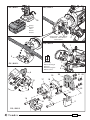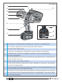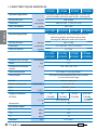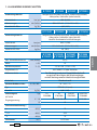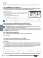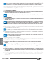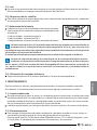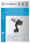
1
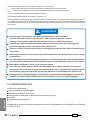
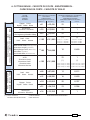
Certified Quality
Management System
Certified Environmental
Management System
Certified Occupational
Health & Safety
Management System
BATTERY OPERATED HYDRAULIC CUTTING TOOL
COUPE-CABLE HYDRAULIQUE SUR BATTERIE
HYDRAULISCHES AKKU-SCHNEIDWERKZEUG
HERRAMIENTA HIDRÁULICA DE CORTE A BATERíA
UTENSILE OLEODINAMICO DA TAGLIO A BATTERIA
ENGLISH
OPERATION AND MAINTENANCE MANUAL ................................... 5
FRANÇAIS
NOTICE D’UTILISATION ET ENTRETIEN ........................................... 10
DEUTSCH
BEDIENUNGSANLEITUNG ................................................................... 15
ESPAÑOL
MANUAL DE USO Y MANTENIMIENTO ........................................... 20
ITALIANO
MANUALE D’USO E MANUTENZIONE............................................. 25
1
14 M 088
B-TC250 B-TC250A B-TC250E B-TC250T
B-TC250Y B-TC250YA B-TC250YE B-TC250YT
FIG. / BILD 1
FIG. / BILD 2
10
Battery
Batterie
Akku
Batería
Batteria
adhesive tape - ruban adhésif
Klebeband - cinta adhesiva
nastro adesivo
5
FIG. / BILD 4
1
2
1
Low battery
Batterie déchargée
Akku leer
Batería descargada
Batteria scarica
FIG. / BILD 3
2
5
4
19
12
17
21 22
20
18
13
23
24
14
16
15
2
FIG. / BILD 5
2
FIG. / BILD 6
1
2
11
3
4
1
5
10
6
9
7
8
1
LED WORKLIGHT / ECLAIRAGE PAR LED / LED ARBEITSLICHT / LUCES LED / ILLUMINAZIONE LED
2
LATCH / LOQUET / VERRIEGELUNG / DIENTE DE RETENCIÓN / DENTE DI ARRESTO
3
HEAD / TETE / KOPF / CABEZA / TESTA
4
LOWER BLADE / LAME INFERIEURE / SCHNEIDMESSER / CUCHILLA INFERIOR / LAMA INFERIORE
5
6
7
8
9
10
11
OPERATING BUTTON / GACHETTE DE COMMANDE / STARTKNOPF / BOTÓN DE ACCIONAMIENTO /
PULSANTE DI AZIONAMENTO
PRESSURE RELEASE BUTTON / GACHETTE DE DECOMPRESSION / DRUCKABLASSKNOPF / BOTÓN DESBLOQUEO
PRESIÓN / PULSANTE DI RILASCIO
BATTERY / BATTERIE / AKKU / BATERÍA / BATTERIA
BATTERY CAPACITY INDICATOR / INDICATEUR DE CHARGE / AKKUANZEIGE / INDICADOR DE CARGA BATERIA /
INDICATORI AUTONOMIA BATTERIA
BATTERY CHECK BUTTON / BOUTON POUR CONTROL DE LA BATTERIE / TASTE FÜR AKKUÜBERPRÜFUNG / BOTÓN
DE CONTROL BATERÍA / PULSANTE DI VERIFICA BATTERIA
BATTERY RELEASE / DEBLOCAGE BATTERIE / AKKU ENTRIEGELUNG / DESBLOQUEO BATERÍA / SBLOCCO BATTERIA
RING FOR SHOULDER STRAP / ANNEAU POUR BANDOULIERE / TRAGERIEMENRING / ANILLO PARA CORREA /
ANELLO AGGANCIO TRACOLLA
3
WARNING SYMBOLS - SYMBOLES D'AVERTISSEMENT - WARNSYMBOLE SÍMBOLOS DE ADVERTENCIA - SIMBOLI DI AVVERTENZA
Tool - Outil - Werkzeug - Herramienta - Utensile
– Before using the tool, carefully read the instructions in this manual.
– Avant d'utiliser cet outil, lire attentivement les instructions de cette notice.
– Vor Inbetriebnahme unbedingt die Bedienungsanleitung durchlesen.
– Antes de utilizar la herramienta, leer atentamente las instrucciones en este manual.
– Prima di utilizzare l'utensile, leggere attentamente le istruzioni riportate in questo manuale.
TG 0960
– Keep hands clear of cutting blades.
– Au cours du coupage, tenir les mains éloignées des lames.
– Während des Schneidens die Hände von den Messern fernhalten.
– Durante el corte, tener las manos alejadas de las cuchillas.
– Durante il taglio, tenere le mani lontane dalle lame.
– Always wear safety glasses and gloves when operating this tool.
– Porter toujours les lunettes de protection et les gants de travail.
– Immer mit Schutzbrille und Handschuhen bedienen.
– Trabajar siempre con las gafas y guantes de seguridad.
– Operare sempre con occhiali di protezione e guanti da lavoro.
– User information (Directives 2002/95/EC and 2002/96/EC), see page 9.
– Information pour les utilisateurs (Directives 2002/95/CE et 2002/96/CE) voir page 14.
– Information für den Benutzer (Richtlinien 2002/95/EG und 2002/96/EG) siehe Seite 19.
– Informe para los usuarios (Directivas 2002/95/CE y 2002/96/CE) vease página 24.
– Informazione agli utenti (Direttive 2002/95/CE e 2002/96/CE) vedere pagina 29.
Battery -Batterie - Akku - Batería - Batteria
– Never throw batteries into fire or water.
– Jamais jeter les batteries dans le feu ou dans l'eau.
– Werfen Sie Akkus nicht in das Feuer oder Wasser.
– Nunca tire las baterías al fuego o al agua
– Mai gettare le batterie nel fuoco o in acqua.
– Always recycle the batteries.
– Recycler toujours les batteries.
– Verbrauchte Akkus stets dem Recycling zuführen.
– Reutilizar siempre las baterías.
– Riciclare sempre le batterie.
– Do not discard batteries into domestic refuse or waste disposal.
– Ne pas jeter de batteries dans une poubelle ou autre lieu non prévu à cet effet.
– Verbrauchte Akkus nicht in den Hausmüll werfen.
– No tirar las baterías al cubo de basura o lugar parecido.
– Non buttate le batterie fuori uso nei cestini della spazzatura o luoghi simili.
4
B-TC250
Application range
Operating pressure
Dimensions
bar (psi)
300 x 337 x 83 (11.8 x 13.3 x 3.3)
kg (lbs)
Application range
Dimensions
4,65 (10.2)
bar (psi)
880 (12,700)
311 x 344 x 83 (12.2 x 13.5 x 3.3)
kg (lbs)
4,8 (10.5)
B-TC250
B-TC250Y
Max. cutting diameter
Motor
Operating temperature
B-TC250YT B-TC250YA
B-TC250YE
suitable for cutting Copper, Aluminium, ACSR and Steel
conductors, ropes and rods (Ref. to pag. 30)
(guy wire including EHS, ground rod up to 5/8")
mm (inches)
Weight with battery
B-TC250A
600 (6,800)
B-TC250Y
Operating pressure
B-TC250T
suitable for cutting Copper, Aluminium, ACSR and Steel
conductors and ropes (Ref. to pag. 30)
mm (inches)
Weight with battery
B-TC250E
mm (inches)
B-TC250E
B-TC250T
B-TC250YE B-TC250YT
B-TC250A
B-TC250YA
25 (1)
V DC
18
°C (°F)
-15 to +50 (+5 to +122)
Recommended oil
AGIP ARNICA 32 or equivalents
Operating speed
twin speed operation and automatic switching from a rapid
advancing speed of the ram to a slower, more powerful speed
Safety
maximum pressure valve
Rechargeable battery
V / Ah / Wh
18 / 4.0 / 72
Type
CB1840L (Li-Ion)
Weight
kg (lbs)
Battery charger
type
ASC30-36
0,66 (1.45)
EU
27044000
UK
27045000
AUS/NZ
27047000
V / Hz
220 - 240 / 50 - 60
W
85
Acoustic noise (1)
LpA
dB (A)
73
LpCPeak
dB (C)
94.5
LWA
dB (A)
79
m/s2
0.575 max.
Input
Vibration (2)
5
USA/CAN
27046000
115 / 60
ENGLISH
1. GENERAL CHARACTERISTICS
ENGLISH
ENGLISH
(1)
Directive 2006/42/EC, annexe 1, point 1.7.4.2 letter u)
LpA = weighted continuous acoustic pressure level equivalent.
LpCPeak = maximum value of the weighted acoustic displacement pressure at the work place.
LWA = acoustic power level emitted by the machine.
(2)
(Directive 2006/42/EC, annexe 1, point 2.2.1.1)
Weighted root mean square in frequency of the acceleration the upper limbs are exposed to for each biodynamic
reference axis. Tests carried out in compliance with the indications contained in UNI ENV 25349 and UNI EN 28662
part 1st Standards, and under operating conditions much more severe than those normally found.
WARNING
Do not use the tool for purposes other than those intended by Cembre.
The operator should concentrate on the work being performed and be careful to maintain a
balanced working position.
Work in a clean, uncluttered area. Keep persons away from immediate work area.
Inspect the blades before each use. Do not use damaged blades.
Damaged blades can break and cause injury or damage to the tool.
Before each use, verify the integrity of the tool; replace any worn, possibly damaged or missing
parts with original Cembre spares.
Wear eye protection. Metal chips can fly from blades when cutting.
Pay attention when cutting short, free pieces of steel rod or rope as they may fly off dangerously,
causing injury to the operator or persons nearby.
Do not cut live cables or conductors.
The tool is unsuitable for continuous use and should be allowed to cool down following uninterrupted, successive cutting operations; for instance, having exhausted a fully charged battery in
one session, delay battery replacement for a few minutes.
Protect the tool from rain and moisture. Water will damage the tool and battery. Electro-hydraulic
tools should not be operated in pouring rain.
2. INSTRUCTIONS FOR USE
The part reference includes the following:
Hydraulic cutting tool.
Li-Ion rechargeable battery (2 pcs).
Battery charger (model depends on the tool version).
Shoulder strap.
Carrying case.
The tool can be easily carried using either the handle or the shoulder strap attached to ring (11)
(Ref. to Fig. 6).
6
To replace the battery, remove it by pressing the release button (10) (Ref. to Fig. 1), then insert
the new battery, sliding it into the guides until it locks.
2.1) Head rotation
For ease of operation, the tool head can rotate through 180°, allowing the operator to work in the
most comfortable position (Ref. to Fig. 2 and 3).
Do not attempt to rotate the head when the hydraulic circuit is pressurised.
2.2) Setting
Insert the conductor between the blades, up to the desired cutting point (Ref. to Fig. 2).
To cut short pieces of steel or ACSR ropes, it is suggested to tie or wrap rope with
adhesive or duct tape around the area to be cut and at its end (Ref. to Fig. 2), so to limit
the projection of steel fragment which could damage or hurt the operator.
For a running conductor, release the latch (2) and open the tool head.
Fully retract the lower blade (4) before attempting to open the tool head (Ref. to § 2.6).
With the conductor on the lower blade (4), close the tool head and fully secure the latch (2) (Ref.
to Fig. 3).
Before commencing the cutting operation ensure that the latch (2) is fully secured: partial
closure may damage the tool head.
2.3) Blade advancement
Operate the push-button (5) (Ref. to Fig. 2) to activate the motor-pump, the ram will gradually
move forward until the lower blade (4) touches the conductor.
To halt the advancement, release the push-button (06) and the motor will cut out.
Make sure the blade is exactly positioned on the desired cutting point otherwise re-open the
blade following instructions as per § 2.6 and reposition it.
2.4) Cutting
Firmly hold the tool and operate the push-button (5) to gradually move the lower blade (4) to
cut through the conductor.
When the cut is performed, release the push-button (5), otherwise after the maximum pressure relief valve has activated (double activation for "Y" versions) and the motor will stop automatically.
7
ENGLISH
Before starting any work, check the battery charge (Ref. to § 2.7) and recharge if necessary,
following the instructions in the battery charger user manual.
ENGLISH
ENGLISH
2.5) LED Worklights
Whilst the tool is in operation, the work area is illuminated by two high luminosity LED Worklights
that switch off automatically at the end of the cycle.
2.6) Blade retraction
By pressing down the pressure release button (6), the ram will retract opening the blades.
2.7) Battery status
The battery is equipped with LED indicators that indicate the
remaining battery life at any time by pressing the adjacent
button (9):
4 LEDs illuminated: fully charged
2 LEDs illuminated: 50 % capacity
1 LED flashing : minimum charge, replace the battery.
9
Tool LEDs (1) illuminated combined with an alarm audible when the operating button (5)
is pressed (Ref. to Fig. 4), indicate that the battery voltage has dropped below a minimum
safety threshold; under these conditions the tool will not start, and it is necessary to recharge or
replace the battery.
The approximate time to fully recharge a battery is about 80 minutes.
After each working cycle, and after the extraction of the battery from the tool, an integrated
battery cut-off device will operate after 70 s approx. Then the LED nearest to button (9) will
flash 5 times each 14 s approx. The battery will be reactivated when it is reintroduced into the tool
and the operating button is pressed.
2.8) Using the battery charger
Carefully follow the instructions in the battery charger user manual.
3. MAINTENANCE
The tool is robust, completely sealed, and requires very little daily maintenance. Compliance with
the following points, should help to maintain its optimum performance:
3.1) Thorough cleaning
Dust, sand and dirt are a danger for any hydraulic device. Every day, after use, the tool must be
wiped with a clean cloth taking care to remove any residue, especially close to pivots and moveable parts.
Do not use hydrocarbons to clean the rubber parts.
Regularly lubricate the moving parts and pivot pins of the head with a few drops of oil.
3.2) Storage case
When not in use, the tool should be stored and transported in the plastic case, to prevent damage.
The case, type VAL P37, is suitable for storing the tool and accessories.
VAL P37: Size 500x480x128 mm (19.7x18.9x5.0 inches). Weight 3,1 kg (6.8 lbs).
8
When changing blades, the battery must first be removed from the tool.
After extended use, the blades may break or loose their cutting edge.
Replace the blades as follows:
–
–
–
–
Lower blade
Release latch (2), and open the tool head completely.
Operate the tool to advance the lower blade (4) and remove the battery.
Eject two split pins (12) from the ram (13) to release the blade (4).
Remove the broken blade to the ram, insert the new blade and fit with two split pins.
Before closing the tool head, push the release button (6) and fully retract the lower blade,
otherwise the tool head assembly may hit and damage, the lower blade.
–
–
–
–
–
–
–
–
–
–
Upper blade
Release latch (2), and fully open the tool head.
Remove circlip (16) and extract the head pin (15) to release the latch.
Remove circlip (23) and latch pin (15) to release the latch.
Remove the latch and recover the latch spring (24).
Using a 10 mm spanner, remove 8 nuts (22) and relevant washers (21).
Remove 4 studs (18), releasing the broken blade (20).
Position the new blade, insert 4 studs (18), fit 8 washers (21) and light tighten 8 nuts (22).
Insert the latch spring (24) into the spacer (19).
Reassemble the latch (2) and fully tighten the 8 nuts (22).
Fit the head assembly to the head support using the pin (14) and circlip (16).
5. RETURN TO Cembre FOR OVERHAUL
In the case of a breakdown, contact your local Agent who will advise you on the problem and give
you the necessary instructions on how to dispatch the tool to our nearest service Centre; if possible,
attach a copy of the Cembre Test Certificate supplied with the tool or, if no other references are
available, indicate the approximate purchase date and the tool serial number.
Following information applies in member states of the European Union:
USER INFORMATION in accordance with “Directives 2002/95/EC and 2002/96/EC.
The ‘Not in the bin’ symbol above when shown on equipment or packaging means that the
equipment must, at the end of its life, be disposed of separately from other waste.
The separate waste collection of such equipment is organised and managed by the manufacturer.
Users wishing to dispose of such equipment must contact the manufacturer and follow the prescribed guidelines for its separate collection. Appropriate waste separation, collection, environmentally
compatible treatment and disposal is intended to reduce harmful environmental effects and promote the reuse and recycling of materials contained in the equipment. Unlawful disposal of such
equipment will be subject to the application of administrative sanctions provided by current legislation.
9
ENGLISH
4. BLADE REPLACEMENT (Ref. to Fig. 5)
1. CARACTERISTIQUES GENERALES
B-TC250
Domaine d'application
Pression de travail
Dimensions
Poids avec batterie
bar (psi)
600 (6,800)
mm (inches)
300 x 337 x 83 (11.8 x 13.3 x 3.3)
kg (lbs)
FRANÇAIS
Domaine d'application
Dimensions
Poids avec batterie
4,65 (10.2)
Moteur
Température de fonctionnement:
B-TC250YT B-TC250YA
B-TC250YE
conçu pour couper des câbles métalliques en cuivre,
aluminium, almelec, aluminium-acier et acier
(voir page 30) idéal pour ronds massif en acier
bar (psi)
880 (12,700)
mm (inches)
311 x 344 x 83 (12.2 x 13.5 x 3.3)
kg (lbs)
4,8 (10.5)
B-TC250
B-TC250Y
Diamètre maxi. de coupe
B-TC250A
B-TC250T
conçu pour couper des câbles métalliques en cuivre, aluminium, almelec, aluminium-acier et acier (voir page 30)
B-TC250Y
Pression de travail
B-TC250E
B-TC250A
B-TC250YA
B-TC250E
B-TC250T
B-TC250YE B-TC250YT
mm (inches)
25 (1)
V DC
18
°C (°F)
-15 à +50 (+5 à +122)
Huile recommandée:
AGIP ARNICA 32 ou équivalents.
Avance rapide:
l’outil passe automatiquement de la vitesse rapide
à la vitesse lente de coupe.
Sécurité
Batterie rechargeable
valve de surpression.
V / Ah / Wh
18 / 4.0 / 72
Type
Poids
Chargeur de batterie
CB1840L (LI-Ion)
kg (lbs)
type
ASC30-36
0.66
EU
27044000
UK
27045000
AUS/NZ
27047000
V / Hz
220 - 240 / 50 - 60
W
85
Bruit aérien sonore (1)
LpA
dB (A)
73
LpCPeak
dB (C)
94.5
LWA
dB (A)
79
m/s2
0.575 maxi.
Alimentation
Vibrations (2)
USA/CAN
27046000
115 / 60
10
(1) (Directive 2006/42/CE, annexe 1, point 1.7.4.2, lettre u)
LpA = niveau de pression sonore continue équivalente pondérée A sur le poste de travail.
LpCPeak =niveau de pression sonore instantanée pondérée C sur le poste de travail.
LWA = niveau de puissance acoustique dégagée par la machine.
(2) (Directive 2006/42/CE, annexe 1, point 2.2.1.1)
AVERTISSEMENT
Ne pas utiliser cet outil à des fins différentes que celles prévues par le constructeur.
Restez bien attentif tout au long du travail, ne soyez pas distrait, ne perdez pas l’équilibre pendant
l'utilisation.
Travailler dans un espace propre et ordonné. Eloigner les personnes de la zone de travail.
Contrôler les lames avant chaque utilisation. Ne pas utiliser l’outil avec une lame endommagée.
Les lames endommagées peuvent abîmer l’outil.
Remplacer les pièces usagées et éventuellement endommagées ou manquantes avec des pièces
de rechange originales Cembre.
Toujours porter une visière de protection pendant les opérations de coupe, car de petits éclats de
câbles peuvent être propulsés.
Attention lors de la coupe de morceaux de câbles courts ou de ronds massif en acier , car ils pourraient être projetés dangereusement et blesser l’opérateur ou une personne proche.
Ne pas couper de câble sous tension électrique.
L’outil n’est pas conçu pour une utilisation en continu; après avoir effectué une quantité de coupe
consécutives à partir d’une batterie complètement chargée, au moment du remplacement de la
batterie, nous suggérons d’observer une période d’arrêt pour permettre le refroidissement de
l’outil.
Protéger l’outil de la pluie et de l’humidité. L’eau pourrait endommager l’outil et la batterie, les
outils hydro-electriques ne devraient pas être utilisés sous la pluie.
2. INSTRUCTIONS D'UTILISATION
L' ensemble comprend:
Outil hydraulique pour couper.
Batterie rechargeable Li-Ion (2 pcs)
Chargeur de batterie (différent en fonction de la version de l'outil).
Bandoulière.
Coffret de rangement.
L’outil peut être transporté facilement grâce à sa poignée et à la bandoulière accrochée par l'anneau
(11) (Réf a Fig. 2).
11
FRANÇAIS
Valeur quadratique moyenne pondérée en fréquence de l'accélération à laquelle sont exposés les membres supérieurs
pour chaque axe biodynamique de référence. Relevés réalisés suivant les indications des Normes UNI ENV 25349 et
UNI EN 28662 partie 1a, dans des conditions de service largement représentatives des conditions d'emploi normales.
Avant de commencer toute opération, contrôler l’état de charge de la batterie (voir § 2.7) et,
si nécessaire, la recharger en suivant les instructions contenues dans le manuel d’utilisation
du chargeur de batteries.
Pour remplacer la batterie, la retirer en appuyant sur le mécanisme de déblocage (10) (Réf. a Fig. 1)
puis introduire la nouvelle batterie en la faisant coulisser sur les guides jusqu’au blocage complet.
2.1) Rotation de la tête
FRANÇAIS
La tête de l'outil pivote de 180° par rapport au corps,permettant à l'utilisateur de travailler dans
la meilleure position.
Ne pas forcer la rotation de la tête, lorsque le circuit hydraulique est sous pression.
2.2) Préparation
Positionner le câble entre les lames de façon à ce qu'elles soient en correspondance avec la
position de coupe souhaitée (Réf. a Fig. 2).
Pour couper de courts morceaux de câbles en acier ou en alu-acier, il est suggéré de lier
ou bien enrouler l’extrémité et le point de coupe avec du ruban adhésif (Réf. a Fig. 2);
ça limitera la projection d’éclats en acier qui pourrait causer des dommages ou lésions à
l’operateur.
Si le câble est passant, il sera alors nécessaire d’ouvrir la tête en tirant le loquet (2) permettant
la rotation et l'ouverture de la tête.
L’ouverture de la tête ne devra être effectuée qu'avec la lame inférieure (4) complètement
baissée.
Poser la lame inférieure (4) contre le câble à couper, refermer la tête en la verrouillant à l’aide
du loquet (2) (Réf. a Fig. 3).
Avant d’effectuer l’opération de coupe, s’assurer que le loquet (2) soit parfaitement enclenché.
2.3) Avance des lames
Appuyer sur la gâchette de commande (5) (Réf. a Fig. 2) pour mettre en marche le groupe
moteur-pompe; la lame inférieure commence l'approche du câble.
La gâchette de commande relâchée, le moteur et l'avance de la lame inférieure cessent immédiatement.
S'assurer que les lames sont bien positionées sur la zone à couper, sinon desserer les lames
en suivant les instructions du § 2.6 et repositioner le câble.
2.4) Coupe
Tenez l'outil fermement y appuyer sur la gâchette de commande (5) pour mettre en marche le
moteur; la lame inférieure avance progressivement jusqu’à ce que le câble soit coupé complètement.
Relâchez la gâchette de commande (5) lorsque la coupe est effectuée.
Si l'on maintient le moteur actionné, l’outil s’arrêtera automatiquement avec l'intervention de la
valve de surpression (double intervention pour les versions "Y").
12
2.5) Led
Lors de l’actionnement de l’outil, la zone de travail est éclairée au moyen de deux LED haute
luminosité qui s’éteignent automatiquement à la fin du cycle.
2.6) Réouverture des lames
En appuyant à fond sur la gâchette de déblocage (6), on provoque le retour du piston et par
conséquent l'ouverture de la lame inférieure.
La batterie est équipée d’indicateurs à LED qui permettent de
contrôler, à tout moment, son autonomie résiduelle en appuyant
sur le bouton (9):
4 led allumées: autonomie maximale
2 led allumées: autonomie à 50 %
1 led clignotante: autonomie minimale, remplacer la batterie.
9
L'éclairage des deux Led (1) associé à l’avertisseur sonore lorsque l’on appuie sur le bouton de
déclenchement (5) (Réf. a Fig. 4) indique que la batterie est déchargée et que sa tension est
descendue au-dessous du seuil minimal de sécurité ; dans cette situation, l’outil ne démarre pas, il
est donc nécessaire de recharger ou de remplacer la batterie.
À titre indicatif, le délai de recharge complète de la batterie correspond à environ 80 min.
A la fin de chaque cycle de travail comme à l’extraction de la batterie de l’outil, un dispositif
électronique arrête automatiquement la batterie après environ 70 s.
Pour confirmer cette opération, la led la plus proche du bouton (9) clignotera 5 fois en 14 s
(approximativement). La batterie est réactivée dès sa réintroduction dans l’outil, ou en appuyant
sur le bouton d’actionnement.
2.8) Utilisation du chargeur de batterie
Suivre attentivement les instructions indiquées sur le manuel.
3. ENTRETIEN
L'outil est robuste, complètement scellé et ne nécessite aucune préoccupation ou attention particulier.
Les recommandations qui suivent sont néanmoins souhaitables pour assurer une longévité optimum:
3.1) Nettoyage élémentaire
Veiller à protéger l'outil de la poussière, du sable et de la boue qui sont un danger à tout système
hydraulique. Chaque jour après utilisation, l'outil doit être nettoyé à l'aide d'un chiffon propre,
tout particulièrement aux endroits de pièces mobiles.
Ne jamais utiliser d’hydrocarbures pour le nettoyage des parties en caoutchouc.
Lubrifier régulièrement les parties mobiles et les axes de la tête avec quelques gouttes d’huile.
3.2) Rangement
Au repos, pour protéger l'outil des coups accidentels et de la poussière, il convient de le ranger
dans le coffret.
Ce coffret (type VAL P37), adapté pour contenir l'outil et ses accessoires a comme dimensions:
500x480x128 mm (19.7x18.9x5.0 inches) et un poids de 3,1 kg (6.8 lbs).
13
FRANÇAIS
2.7) Autonomie de la batterie
4. CHANGEMENT DES LAMES (Voir Fig. 5)
Changement des lames doivent être effectuées avec l’outil dépourvu de batterie.
FRANÇAIS
Il peut arriver qu' une utilisation prolongée ou non appropriée cause la perte d’affûtage des lames
ou leur endommagement. Le changement des lames est cependant très simple.
–
–
–
–
Lame inférieure
Déverrouiller le loquet (2) et ouvrir le groupe supérieur, jusqu’à la butée.
Actionner l'outil pour faire avancer la lame inférieure (4) et enlever la batterie.
Expulser les goupilles élastiques (12) sur le piston (13) de façon à libérer la lame (4).
Enlever la vieille lame et introduire la lame neuve sur le piston et la bloquer avec les 2 goupilles
elastiques.
Avant de refermer la tête appuyer sur la gâchette de déblocage (6) de façon à ce que la lame
inférieure redescende complètement pour éviter qu’elle soit heurtée et endommagée.
Lame supérieure
Déverrouiller le loquet (2) et ouvrir le groupe supérieur, jusqu’à la butée.
Enlever l’anneau élastique (16), extraire l’axe (14) pour libérer le groupe supérieur de la tête.
Enlever l’anneau élastique (23), extraire l’axe (15) et dégager le loquet (2).
Enlever le loquet (2) et récupérer le ressort (24).
A l’aide d’une clé de “10”, enlever les 8 écrous (22) et les rondelles (21).
Extraire les 4 goujons (18) de façon à libérer la lame (20).
La remplacer par la neuve, replacer les 4 goujons (18), les rondelles (21) et serrer manuellement
les 8 écrous (22); introduire le ressort (24) dans le logement correspondant de l’entretoise (19).
– Remonter le loquet (2) sur le groupe supérieur, serrer les 8 écrous (22) à fond.
– Placer le groupe supérieur, introduire l’axe (14) et le bloquer avec son anneau élastique (16).
–
–
–
–
–
–
–
5. ENVOI EN REVISION A Cembre
En cas de dysfonctionnement de l'appareil, merci de vous adresser à notre Agent Régional qui
vous conseillera et le cas échéant vous donnera les instructions nécessaires pour envoyer l'outil
à notre Centre de Service le plus proche. Dans ce cas, joindre une copie du Certificat d'Essai livré
par Cembre avec l'outil ou, à défaut d'autres éléments de référence, indiquer la date d'achat approximative et numéro de série.
Les informations suivantes sont destinées aux pays membres del'Union Européenne:
INFORMATION POUR LES UTILISATEURS aux termes des “Directives 2002/95/CE et 2002/96/CE.
Le symbole “poubelle barrée” apposé sur l’appareil ou sur son emballage indique que le produit, à la
fin de sa vie utile, doit être recueilli séparément des autres déchets.
La collecte sélective du présent appareil en fin de vie est organisée et gérée par le producteur. L’utilisateur qui voudra se défaire du présent appareil devra par conséquent contacter le producteur et
suivre le système que celui-ci a adopté pour consentir la collecte séparée de l’appareil en fin de vie.
La collecte sélective adéquate pour l’envoi successif de l’appareil destiné au recyclage, au traitement
et à l’élimination compatible avec l’environnement contribue à éviter les effets négatifs possibles
sur l’environnement et sur la santé et favorise la réutilisation ou le recyclage des matériaux dont
l’appareil est composé. L’élimination abusive du produit par le détenteur comporte l’application des
sanctions administratives prévues par les lois en vigueur.
14
1. ALLGEMEINE EIGENSCHAFTEN
B-TC250
Anwendungsbereich
Geeignet zum Schneiden von Kupfer- und Aluminiumkabeln,
Aldreyseilen, Stahlseilen (siehe Seite 30)
bar (psi)
Abmessungen
Gewicht inkl. Akku
600 (6,800)
mm (inches)
300 x 337 x 83 (11.8 x 13.3 x 3.3)
kg (lbs)
4,65 (10.2)
B-TC250Y
Anwendungsbereich
Arbeitsdruck
Gewicht inkl. Akku
Motor
mm (inches)
311 x 344 x 83 (12.2 x 13.5 x 3.3)
kg (lbs)
4,8 (10.5)
mm (inches)
B-TC250E
B-TC250T
B-TC250YE B-TC250YT
B-TC250A
B-TC250YA
25 (1)
V DC
Betriebstemperatur:
B-TC250YT B-TC250YA
880 (12,700)
B-TC250
B-TC250Y
Max. Schneiddurchmesser
B-TC250YE
Geeignet zum Schneiden von Kupfer- und Aluminiumkabeln,
Aldreyseilen, Stahlseilen (siehe Seite 30).
Ideal für Rundmaterial und Stahlstangen.
bar (psi)
Abmessungen
B-TC250A
B-TC250T
18
°C (°F)
-15 bis +50 (+5 bis +122)
Empfohlenes Öl:
AGIP ARNICA 32 oder ähnliches
Kolbenvorschub:
Das Werkzeug ist mit einer Doppelkolbenhydraulik
ausgerüstet. Beim Beginn des Arbeitsvorganges
wird auf den langsameren Arbeitshub umgeschaltet.
Sicherheit:
Überdruckventil
Wiederaufladbarer Akku
V / Ah / Wh
18 / 4.0 / 72
Typ
CB1840L (Li-Ionen)
Gewicht
kg (lbs)
Akkuladegerät
Typ
ASC30-36
0,66 (1.45)
EU
27044000
UK
27045000
AUS/NZ
27047000
V / Hz
220 - 240 / 50 - 60
W
85
Lärmschutzbestimmung (1)
LpA
dB (A)
73
LpCPeak
dB (C)
94.5
LWA
dB (A)
79
m/s2
0.575 max.
Eingangspannung
Vibrationen (2)
15
USA/CAN
27046000
115 / 60
DEUTSCH
Arbeitsdruck
B-TC250E
(1) Richtlinie 2006/42/EG, Anhang 1, Nummer 1.7.4.2, Buchstabe u)
LpA = konstanter Lärmpegel entsprechend Gewichtung A am Arbeitsplatz
LpCPeak = höchster Lärmpegel entsprechend Gewichtung C am Arbeitsplatz
LWA = Lärmbelastung des Geräts
(2) Richtlinie 2006/42/EG, Anhang 1, Nummer 2.2.1.1)
Der Wert bezieht sich auf Messungen, entsprechend der Normen UNI ENV 25349 und UNI EN 28662 Teil 1 unter repräsentativen Bedingungen, bei dem der durchschnittliche Messwert an den oberen Teilen den Wert nicht überschritt.
DEUTSCH
HINWEISE
Verwenden Sie das Akkuwerkzeug ausschließlich für den vom Hersteller vorgesehenen Anwendungszweck.
Arbeiten Sie konzentriert und lassen Sie sich während des Einsatzes nicht ablenken und nehmen
zur Arbeit eine sichere und standfeste Arbeitsposition ein!
Den Arbeitsbereich immer sauber halten und es sollten sich keine weitere Menschen im Arbeitsbereich aufhalten.
Überprüfen Sie die Schneidmesser vor jedem Gebrauch. Verwenden Sie nie ein Werkzeug mit
beschädigten Schneidmessern. Defekte Schneidmesser könnten das Werkzeug stark beschädigen.
Vor jeder Benutzung die Unversehrtheit des Kopfes überprüfen. Verschlissene, beschädigte oder
fehlende Teile durch Originalersatzteile von Cembre ersetzen.
Tragen Sie immer eine Schutzbrille, da sich beim Schneiden Metallsplitter lösen können.
Achten Sie beim Schneiden von Stangen und Stahlseilen darauf, dass sich keine Personen in der
Nähe aufhalten. Es können sich kleine Teile lösen und dann zu Verletzungen führen können.
Es dürfen keine unter Spannung stehenden Teile geschnitten werden.
Die Akkuwerkzeuge sind nicht für einen Dauereinsatz geeignet. Wenn ein voll geladener Akku
durch hintereinander ausgeführte Schnitte getauscht werden muss, empfehlen wir vor dem
Akkuwechsel das Werkzeug eine angemessene Zeit abkühlen zu lassen.
Das Werkzeug vor Regen und Feuchtigkeit schützen. Wasser könnte das Werkzeug und den Akku
beschädigen. Elektrohydraulische Werkzeuge sollten nicht im Regen oder unter fließendem
Wasser eingesetzt werden.
2. BEDIENUNGSHINWEISE
Zum Lieferumfang unter dieser Bezeichnung gehören folgende Teile:
Hydraulisches Akku-Schneidwerkzeug
2 Stück wiederaufladbare Li-Ion Akkus
Ladegerät (entsprechend der Länderkonfiguration)
Trageriemen
Koffer
Das Werkzeug kann bequem am Griff oder mit dem Trageriemen, der am Ring (Bild 6 T.11) befestigt
ist, transportiert werden.
16
Überprüfen Sie vor jedem Arbeitsvorgang den Ladezustand der Akkus (siehe Pkt. 2.7) und
laden Sie bei Bedarf die Akkus entsprechend den Anweisungen in der Bedienungsanleitung
des Akkuladegerätes auf.
Drücken Sie für den Akkuaustausch auf die Entriegelung (10) (siehe Bild 1) und führen Sie den
neuen Akku bis zum Einratsen ein.
2.1) Drehbewegung des Kopfes
Das Werkzeug ist mit einem Kopf ausgerüstet, der um 180° drehbar ist und somit ein komfortables
Arbeiten ermöglicht (siehe Bild 2 und 3).
Der Kopf darf keinesfalls in eine andere Position gedreht werden, während das Werkzeug
unter Druck steht.
2.2) Vorbereitung
Das zu schneidende Seil am gewünschten Schnittpunkt zwischen den Schneidmessern positionieren (siehe Bild 2).
Wenn kurze Abschnitte von Stahl- bzw. Aluminium-Stahl Seilen geschnitten werden,
ist es ratsam das Ende mit Isolierband zu fixieren (siehe Bild 2). Damit werden mögliche
Verletzungen des Anwenders verhindert.
Das Öffnen des Gegenmessers darf nur mit ganz zurückgefahrenem Schneidmesser (4)
erfolgen (siehe Pkt. 2.6).
Das Schneidmesser (4) um das zu schneidende Seil legen. Den Kopf schliessen und die Verriegelung (2) einrasten lassen (siehe Bild 3).
Vor dem Schneiden hat man sich zu vergewissern, daß die Verriegelung (2) einwandfrei
eingerastet ist.
2.3) Schneidvorgang
Durch Drücken des Startknopfes (5) (siehe Bild 2) wird der Pumpenmotor gestartet, wobei sich
das Schneidmesser dem Seil annähert.
Das Zusammenfahren der Schneidmesser kann durch Loslassen des Startknopfes (5) gestoppt
werden.
Auf diese Weise kann kontrolliert werden, dass sich die Schneidmesser genau auf dem
zu schneidenden Punkt befinden. Ist dies nicht der Fall, sind die Schneidmesser zu öffnen
(siehe § 2.6) und erneut zu positionieren.
2.4) Schneiden
Halten Sie das Werkzeug fest und durch Drücken des Startknopfes (5) beginnt der Motor zu
arbeiten, der Kolben lässt das Schneidmesser allmählich nach vorn fahren, bis das Seil vollständig
geschnitten worden ist.
Wenn der Schnitt ausgeführt ist, den Startknopf (5) loslassen. Wenn der Startknopf weiter
betätigt wird, arbeitet das Werkzeug weiter bis zur Abschaltung durch das Überdruckventil (bei
der Y-Ausführung hört man ein Doppelklick).
17
DEUTSCH
Bei durchgehendem Seil wird das Gegenmesser durch Öffnen der Verriegelung (2) zurückgeklappt.
2.5) LED
Während der Betätigung des Werkzeugs wird der Schneidbereich von zwei LED-Anzeigen mit
hoher Helligkeit ausgeleuchtet, die sich am Zyklusende automatisch abschalten.
2.6) Zurückfahren des Schneidmessers
Drücken Sie kräftig des Druckablassknopf (6) , der sich unterhalb des Startknopfes (5) befindet.
Dadurch fährt der Kolben zurück und das Schneidmesser gibt das Kabel frei.
2.7) Akkuladung
Die Akku ist mit LED-Anzeigen ausgestattet, die jederzeit über
die verbleibende Akkulaufzeit Auskunft gibt, indem man auf
die Taste (9) drückt:
4 LED eingeschaltet: Maximale Ladung
2 LED eingeschaltet: Ladung zu 50 %
1 LED blinkend: Minimale Ladung, Akku austauschen bzw. aufladen.
9
DEUTSCH
Wenn der Akku nicht mehr ausreichende Ladung hat, wird beim Betätigen des Startknopfes
(5) über die LED Leuchten (1) zusammen mit einem akustischen Signal das Erreichen des
Mindestsicherheitsniveau signalisiert. Unter diesen Bedingungen kann das Werkzeug nicht in Betrieb
genommen werden. Laden Sie den Akku auf oder tauschen Sie ihn aus.
Ein vollständiger Ladevorgang eines leeren Akkus dauert etwa 80 Minuten.
Nach jedem Arbeitszyklus und wie auch nach der Entfernung des Akkus schaltet es durch
die eingebaute Elektronik nach ca. 70s automatisch ab.
Als Bestätigung des Vorganges wird die LED bei der Taste (9) 5-mal hintereinander innerhalb von
ca. 14s blinken. Durch das Einführen des Akkus in das Werkzeug wird der Akku wieder aktiviert oder
durch die Betätigung des Startknopfes.
2.8) Verwendung des Ladegerätes
Die in der Bedienungsanleitung gegebenen Hinweise sind zu beachten.
3. WARTUNG
Das Werkzeug ist robust und benötigt keine spezielle Pflege.
Zur Erhaltung der Garantieansprüche beachten Sie folgende Hinweise:
3.1) Pflege
Dieses hydraulische Werkzeug sollte vor starker Verschmutzung geschützt werden, da dies für
ein hydraulisches System gefährlich ist. Jeden Tag nach der Arbeit sollte das Werkzeug mit einem
Tuch von Schmutz und Staub gereinigt werden, besonders die beweglichen Teile. Verwenden
Sie keine Kohlenwasserstoffe (z.B. Teilereiniger, Bremsenreiniger) zum Reinigen der Gummiteile.
Alle beweglichen Teile und Bolzen regelmäßig mit einem Tropfen Öl einölen.
3.2) Lagerung
Wenn das Werkzeug nicht benötigt wird, sollte es in dem Kunststoffkoffer gelagert werden und ist
somit gegen Beschädigungen wie Stoß und Staub geschützt.
Der Kunststoffkoffer Typ VAL P37 hat folgende Abmessungen: 500x480x128 mm (19.7x18.9x5.0
inches) und ein Gewicht von 3,1 kg (6.8 lbs.). Er ist geeignet zum Lagern vom Werkzeug und Zubehör.
18
4. SCHNEIDMESSER WECHSELN (Siehe Bild 5)
Wechsel der Schneidmessern muss immer mit ausgebautem Akku erfolgen.
Nach längerem Gebrauch oder nach Anwendungsfehlern kann es zu Abnutzungen (beschädigt,
unscharf ) an den Messern kommen. Bei einem Wechsel sollten Sie wie folgt vorgehen:
–
–
–
–
Schneidmesser
Den Kopf durch Betätigung der Verriegelung (2) öffnen.
Den Motor betätigen und das Schneidmesser (4) nach vorne fahren und entfernen Sie den Akku.
Die beiden Federstifte (12) vom Kolben (13) entfernen und somit kann das Schneidmesser (4)
entfernt werden.
Anschließend mit der Federstifte das neue Schneidmesser wieder montieren.
–
–
–
–
–
–
–
Gegenmesser
Den Kopf durch Betätigung der Verriegelung (2) öffnen.
Den Federring (16) entfernen und den Bolzen (14) soweit herausziehen, dass der obere
Teil des Schneidkopfes abgenommen werden kann.
Den Federring (23) und Bolzen (15) demontieren, dabei wird die Verriegelung auch
entfernt. Die Feder (24) aus ihrem Sitz im Abstandsstück demontieren.
Die 8-er Muttern (22) mit einem “10”-Schlüssel lösen, die Zugbolzen (18) und Scheiben (21)
herausziehen und das Gegenmesser (20) demontieren.
Das Gegenmesser durch ein neues Messer ersetzen. Anschließend die 4 Zugbolzen (18) und
Muttern (22) mit den Scheiben (21) leicht anziehen. Die Feder (24) in ihren Sitz im Abstandsstück
(19) montieren.
Der Verriegelung (2) montieren und die 8-er Muttern (22) fest anziehen.
Die obere Gruppe auf dem Schneidkopf mit dem Bolzen (14) und Federring (16) montieren.
5. EINSCHICKEN AN Cembre ZUR ÜBERPRÜFUNG
Sollten am Gerät Fehler auftauchen, wenden Sie sich bitte an unsere Gebietsvertretung, welche
Sie gerne beraten und Ihnen alle nötigen Informationen zum Einschicken des Gerätes an unseren
Hauptsitz geben wird. Wenn vorhanden, legen Sie dem Gerät bitte das von Cembre mitgelieferte
Überprüfungszertifikat bei; In Ermangelung dieser Informationen geben Sie bitte an, wann Sie das
Gerät erworben haben.
Die folgenden Hinweise gelten für Mitglieder der Europäischen Union:
INFORMATION FÜR DEN BENUTZER gemäß der “Richtlinien 2002/95/EG und 2002/96/EG.
Das durchkreuzte Zeichen auf dem Mülleimer, welches auf dem Gerät oder seiner Verpackung angebracht ist, zeigt an, dass das Produkt am Ende seiner Lebenszeit getrennt von den anderen Abfällen
entsorgt werden muss. Die getrennte Abfallsammlung des vorliegenden zu entsorgenden Geräts
wird vom Hersteller organisiert und verwaltet. Der Besitzer, der sich des Geräts entledigen will, muss
sich daher mit dem Hersteller in Verbindung setzen und das von ihm angenommene System für die
getrennte Sammlung des zu entsorgenden Geräts befolgen.
Eine angemessene getrennte Sammlung, damit das Gerät für das Recycling, die Behandlung und
die umweltfreundliche Entsorgung vorbereitet werden kann, trägt dazu bei, mögliche negative
Auswirkungen auf die Umwelt und auf den Gesundheitszustand zu vermeiden und begünstigt die
Wiederverwertung und das Recycling der Materialien des Geräts. Bei widerrechtlicher Entsorgung
des Produkts durch den Benutzer werden die vom Gesetz vorgesehen Verwaltungssanktionen angewandt.
19
DEUTSCH
Bevor das Gegenmesser wieder geschlossen wird, drücken Sie kräftig den Druckablassknopf
(6), so wird sichergestellt dass das Schneidmesser komplett zurück gefahren ist und es nicht
zu einer Beschädigung der Schneidmesser kommt.
1. CARACTERíSTICAS GENERALES
B-TC250
Campo de aplicación:
Presión de trabajo
Dimensiones
Peso con batería
bar (psi)
600 (6,800)
mm (inches)
300 x 337 x 83 (11.8 x 13.3 x 3.3)
kg (lbs)
Campo de aplicación:
Dimensiones
Peso con batería
4,65 (10.2)
Motor
bar (psi)
B-TC250YT B-TC250YA
880 (12,700)
mm (inches)
311 x 344 x 83 (12.2 x 13.5 x 3.3)
kg (lbs)
4,8 (10.5)
mm (inches)
B-TC250A
B-TC250YA
B-TC250E
B-TC250T
B-TC250YE B-TC250YT
25 (1)
V DC
Temp. de funcionamiento
18
°C (°F)
-15 a +50 (+5 a +122)
Aceite recomendado
AGIP ARNICA 32 ó equivalentes.
Velocidad de avance
son dos: una rápida y otra más lenta de trabajo.
El paso de una a otra velocidad es automático.
Seguridad
ESPAÑOL
B-TC250YE
idónea para cortar cables y varillas de cobre, aldrey,
aluminio, aluminio-acero (Ref. a pag. 30),
ideal para varillas de acero.
B-TC250
B-TC250Y
Diámetro max. de corte
B-TC250A
B-TC250T
idónea para cortar cables de cobre, aldrey,
aluminio, aluminio-acero y acero (Ref. a pag. 30).
B-TC250Y
Presión de trabajo
B-TC250E
válvula de sobrepresión.
Batería recargable
V / Ah / Wh
18 / 4.0 / 72
Tipo
CB1840L (Li-Ion)
Peso
kg (lbs)
Cargador de batería
tipo
ASC30-36
0,66 (1.45)
EU
27044000
UK
27045000
AUS/NZ
27047000
V / Hz
220 - 240 / 50 - 60
W
85
dB (A)
73
LpCPeak
dB (C)
94.5
LWA
dB (A)
79
Alimentación
Ruido aéreo
LpA
Vibraciones (2)
USA/CAN
27046000
115 / 60
(1)
m/s2
0.575 max.
20
(1) Directiva Europea 2006/42/CE, anexo 1, punto 1.7.4.2, letra u)
LpA = nivel de presión acústica contínua equivalente ponderado A en el puesto de trabajo.
LpCPeak = nivel máximo de la presión acústica instantánea ponderada C en el puesto de trabajo.
LWA = nivel de potencia acústica emitida por la máquina.
(2) Directiva Europea 2006/42/CE, anexo 1, punto 2.2.1.1)
Valor cuadrático medio ponderado en frecuencia, de la aceleración a la que están expuestos los miembros superiores para cada eje biodinámico de referencia. Medidas realizadas según las indicaciones de las Normas UNI ENV
25349 y UNI EN 28662 parte 1a, en condiciones de utilización ampliamente representativas respecto a las que se
encuentran normalmente.
ADVERTENCIAS
2. INSTRUCCIONES DE USO
La sigla identifica el conjunto formado por:
Herramienta hidráulica de corte
Batería recargable Li-Ion (2 uds)
Cargador de batería (diferente según el modelo de la herramienta)
Correa de transporte
Caja de contención
La herramienta puede ser transportada fácilmente por medio del asa o la correa de transporte fijada
al anillo (11) (Ref. a Fig. 6).
21
ESPAÑOL
No utilice la herramienta para fines diferentes de los previstos por el fabricante.
Prestar atención en el trabajo, no distraerse y no perder el equilibrio durante la utilización.
Operar en área de trabajo limpia y despejada. Mantener alejadas las personas del área de trabajo.
Antes de cada uso, inspeccionar las cuchillas antes de utilizar la herramienta. No utilizar la herramienta con las cuchillas dañadas. Cuchillas dañadas pueden causar la rotura de la herramienta.
Sustituir las partes desgastadas, dañadas o ausentes con piezas de recambio originales Cembre.
Operar siempre con las gafas de trabajo; durante las operaciones de corte pueden originarse
esquirlas metálicas.
Prestar atención a cortar trozos cortas de varillas o cables de acero que pudieran ser proyectados peligrosamente a distancia causando daños al operario y a las personas cercanas.
No cortar conductores o cables con tensión eléctrica.
La herramienta no esta preparada para un empleo continuo; una vez ejecutado el numero de
operaciones máximo permitido por una batería, a la hora de cambiarla, aconsejamos un oportuno
período de pausa para permitir el enfriamiento de la herramienta.
Proteger la herramienta de la lluvia y la humedad. El agua podría dañar la herramienta y la
batería. Las herramientas electrohidráulicas no deberían funcionar bajo la lluvia o debajo
del agua.
Antes de iniciar cualquier trabajo, compruebe el estado de carga de las baterías (Ref. al § 2.7).
Si es necesario, recárguelas siguiendo las instrucciones del manual de uso del cargador.
Para sustituir la batería, retírela pulsando el desbloqueo (10) (Ref. a Fig. 1) y luego inserte la nueva
batería deslizándola por las guías hasta su tope.
2.1) Rotación de la cabeza
La cabeza de la herramienta puede rotar hasta 180° respecto al cuerpo, permitiendo al operario
realizar el trabajo en la posición más adecuada (Ref. a Fig. 2 y 3).
No fuerce la cabeza, intentando rotarla, mientras el circuito hidráulico esté presurizado.
2.2) Preparación
Colocar el conductor entre las cuchillas de manera que éstas se encuentren en el punto de corte
deseado (Ref. a Fig. 2).
Al cortar piezas cortas de los cables de acero o de aluminio-acero, se recomienda de atar
o envolver el extremo y el punto de corte con cinta aislante o similar (Ref. a Fig. 2); esto
evitará la proyección de fragmentos de acero que podrían causar daños o lesiones personales.
Si el conductor es pasante, será necesario abrir la cabeza, desenganchando el diente de retención
(2) y hacer girar el conjunto superior.
Se puede abrir la cabeza cuando la cuchilla inferior (4) está completamente retraída.
Colocar la cuchilla inferior (4) sobre el conductor a cortar, volver a cerrar el grupo superior bloqueándolo con el diente de retención (2).
Antes de proceder con la operación de corte, comprobar que el diente de retención (2)
esté enganchado perfectamente.
ESPAÑOL
2.3) Acercamiento de las chuchillas
Pulsar el botón de accionamiento (5) (Ref. a Fig. 2) para poner en marcha el grupo motor-bomba;
la cuchilla inferior empieza a acercarse al conductor.
Soltando el botón se detienen inmediatamente tanto el motor como el movimiento de la
cuchilla.
Asegúrese de que la cuchilla se encuentra en correspondencia con la zona a cortar; en
caso contrario, vuélvala a abrir siguiendo las instrucciones del punto 2.6 y reposicionarse.
2.4) Corte
Sostenga firmemente la herramienta y pulsar el botón de accionamiento (5), el motor continúa
girando; el pistón hará avanzar progresivamente la cuchilla inferior hasta cortar completamente
el conductor.
Cuando el corte esta realizado, soltar el botón (5), de lo contrario el motor se detendrá automáticamente después de la intervención de la válvula de sobrepresión (intervención doble para las
versiones "S").
22
2.5) Led
Durante el accionamiento de la herramienta, la zona de trabajo está iluminada por dos led de a
alta luminosidad que se apagan automáticamente al final del ciclo.
2.6) Reapertura de las cuchillas
Para volver a obtener el retorno del pistón, actuar sobre el botón de desbloqueo (6), se obtendrá
el consiguiente retorno de la cuchilla .
2.7) Autonomía de la batería
La batería está provista de indicadores de led que permiten
saber la autonomía restante en cualquier momento pulsando
el botón (9):
4 led encendidos: autonomía máxima
2 led encendidos: autonomía al 50 %
1 led parpadeante: autonomía mínima, reemplezar la batería.
9
La iluminación de los 2 Led (1) asociada a una señal acústica cuando se presiona el botón de
accionamiento (5) indica que la batería está descargada (Ref. a Fig. 4) y que su tensión está
por debajo de un punto mínimo de seguridad; en estas condiciones la herramienta no se inicia, proceda
a la recarga o a la sustitución de la batería.
El tiempo aproximado para recargar completamente una batería descargada es de 80 min.
Después de cada ciclo de trabajo, así como después de la extracción de la batería de la herramienta, un dispositivo electrónico permite el apagado automático de la batería después
de 70 s, aprox. y el LED más cercano del botón (9) parpadeará 5 veces consecutivas a intervalos de
14 s, aprox. La batería se reactivará con su reinserción en la herramienta y pulsando el botón de
accionamiento.
2.8) Utilización del cargador de batería
Seguir atentamente las instrucciones detalladas en el manual correspondiente.
Esta herramienta es robusta, completamente precintada y no requiere cuidados especiales .
Para obtener un funcionamiento correcto, bastará tener algunas precauciones sencillas:
3.1) Limpieza adecuada
Tenga presente que el polvo, la arena y la suciedad en general, representan un peligro para toda
herramienta hidráulica. Tras cada día de uso, se debe limpiar la herramienta con un trapo limpio,
teniendo cuidado de eliminar la suciedad depositada, especialmente junto a las partes móviles.
No use hidrocarburos para la limpieza de las partes de caucho.
Lubrificar regularmente, con unas gotas de aceite, las partes móviles y los pernos de la cabeza.
3.2) Almacenamiento
Para proteger la herramienta de golpes accidentales y del polvo cuando no se va a utilizar, es
conveniente guardarla cerrada en su caja de plástico de cierre hermético.
Dicho estuche tipo VAL P37 de dimensiones 500x480x128 mm (19.7x18.9x5.0 pulgadas) y pes
3,1 kg (6.8 lbs), es apropiado para almacenar la herramienta y los accesorios.
23
ESPAÑOL
3. MANTENIMIENTO
4. CAMBIO DE LAS CUCHILLAS (Ref. a Fig. 5)
El cambio de las cuchillas debe ser efectuado con la herramienta sin batería.
Puede suceder que las cuchillas se estropeen tras un uso prolongado o impropio.
Para efectuar el cambio de las cuchillas, actue como sigue:
Cuchilla inferior
– Abrir la cabeza desenganchando el diente de retención (2) y hacer girar completamente el
conjunto superior hasta el tope.
– Accionar el motor haciendo avanzar la cuchilla inferior (4) y quitar la batería.
– Expulsar los dos pasadores elásticos (12) en el pistón (13) y soltar asi la cuchilla (4).
– Sacar la cuchilla vieja, colocar la nueva en el pistón y sujetarla con los dos pasadores elásticos.
Antes de volver a cerrar el conjunto superior, actuar sobre el botón de desbloqueo (6)
haciendo retroceder completamente la cuchilla; en caso contrario, el conjunto superior
podría chocar contra la arista de la cuchilla inferior y estropearla.
Cuchilla superior
–
–
–
–
–
–
–
Abrir la cabeza desenganchando el diente de retención (2) y girarla completamente.
Quitar el aro (16), extraer el pasador (14) para soltar completamente el conjunto superior.
Quitar el aro (23), extraer el pasador (15)
Separar el diente de retención (2) y recuperar el muelle (24).
Con una llave del “10”, quitar las 8 tuercas (22) y extraer las arandelas (21)
Quitar los 4 espárragos (18) de manera que se suelte la cuchilla superior (20).
Reemplazarla con la nueva, colocar los 4 espárragos (18), las arandelas (21) y apretar a mano
las 8 tuercas (22); insertar el muelle (24) en su alojamiento del distanciador (19).
– Montar el diente de retención (2) y apretar a fondo las 8 tuercas (22).
– Colocar el grupo superior, insertar a fondo el pasador (14) y sujetarlo con el aro (16).
ESPAÑOL
5. DEVOLUCION A Cembre PARA REVISIONES
En caso de fallo de la herramienta, contactar con nuestro Agente de Zona quien les aconsejará y
eventualmente les facilitará las instrucciones necesarias para remitir la herramienta a nuestro centro
de servicio más cercano. En tal caso, adjuntar a ser posible una copia del Certificado de Ensayo entregado en su día por Cembre con la herramienta o a falta de otro elemento de referencia indicar
la fecha de compra aproximada y el número de serie.
Las siguientes informaciones conciernen a los estados miembros de la Unión Europea:
INFORME PARA LOS USUARIOS en los términos de las Directivas 2002/95/CE y 2002/96/CE.
El símbolo del contenedor de basura cruzado por un aspa que aparece en el equipo o sobre su embalaje indica que, al final de su ciclo de vida útil, el producto debe ser eliminado independientemente
de otros desechos. La recogida selectiva del presente equipo, llegado al final de su ciclo de vida,
es organizada y manejada por el fabricante. El usuario que desee deshacerse del presente equipo
deberá, por lo tanto, contactar con el fabricante y seguir el sistema adoptado por el mismo para permitir la recogida por separado del equipo que ha concluido su ciclo de vida. La adecuada recogida
selectiva, para el sucesivo envío del equipo dado de baja al reciclaje, al tratamiento y al saneamiento ambiental compatible, contribuye a evitar posibles efectos negativos sobre el medio ambiente y
sobre la salud favoreciendo el reempleo y el reciclaje de los materiales que componen el equipo. La
eliminación abusiva del equipo por parte del propietario implica la aplicación de las sanciones administrativas prevista por la legislación vigente.
24
1. CARATTERISTICHE GENERALI
B-TC250
Campo di applicazione
Pressione di esercizio
Dimensioni
bar (psi)
300 x 337 x 83 (11.8 x 13.3 x 3.3)
kg (lbs)
Campo di applicazione
Dimensioni (Rif. a Fig. 5)
Peso con batteria
4,65 (10.2)
Motore
Temperatura di utilizzo
B-TC250YT B-TC250YA
B-TC250YE
adatto al taglio di conduttori e funi in rame, alluminio,
aldrey, acciaio e aluminio-acciaio (rif. a pag. 30),
ideale per tondi in acciaio.
bar (psi)
880 (12,700)
mm (inches)
311 x 344 x 83 (12.2 x 13.5 x 3.3)
kg (lbs)
4,8 (10.5)
B-TC250
B-TC250Y
Diametro max. di taglio
B-TC250A
600 (6,800)
B-TC250Y
Pressione di esercizio
B-TC250T
adatto al taglio di conduttori e funi in rame, alluminio, aldrey,
acciaio e aluminio-acciaio (rif. a pag. 30)
mm (inches)
Peso con batteria
B-TC250E
mm (inches)
B-TC250E
B-TC250T
B-TC250YE B-TC250YT
B-TC250A
B-TC250YA
25 (1)
V DC
18
°C (°F)
-15 a +50 (+5 a +122)
Olio consigliato
AGIP ARNICA 32 o equivalenti.
Velocità di avanzamento
sono due, una rapida ed una più lenta di lavoro.
La commutazione da una all'altra é automatica.
Sicurezza
valvola di massima pressione
Batteria ricaricabile
V / Ah / Wh
18 / 4.0 / 72
Tipo
CB1840L (Li-Ion)
kg (lbs)
Caricabatteria ASC30-36
tipo
0,66 (1.45)
EU
27044000
UK
27045000
AUS/NZ
27047000
V / Hz
220 - 240 / 50 - 60
W
85
Rumore aereo (1)
LpA
dB (A)
73
LpCPeak
dB (C)
94.5
LWA
dB (A)
79
m/s2
0.575 max.
Alimentazione
Vibrazioni (2)
25
USA/CAN
27046000
115 / 60
ITALIANO
Peso
(1) Direttiva Europea 2006/42/CE, allegato 1, punto 1.7.4.2, lettera u)
LpA = livello di pressione acustica continuo equivalente ponderato A nel posto di lavoro.
LpCPeak = valore massimo della pressione acustica istantanea ponderata C nel posto di lavoro.
LWA = Il livello di potenza acustica emessa dalla macchina.
(2) Direttiva Europea 2006/42/CE, allegato 1, punto 2.2.1.1.
Valore quadratico medio ponderato, in frequenza, dell'accelerazione cui sono esposte le membra superiori, per ciascuno degli assi biodinamici di riferimento derivante da rilievi condotti secondo le indicazioni delle Norme UNI ENV
25349 e UNI EN 28662 parte 1a, in condizioni di utilizzo ampiamente rappresentative rispetto a quelle normalmente
riscontrabili.
AVVERTENZE
Non impiegare l'utensile per scopi diversi da quelli previsti dal costruttore.
Prestare attenzione al lavoro, non distrarsi e non sbilanciarsi durante l'utilizzo.
Lavorare in area pulita e sgombra. Tenere lontane le persone dall’area di lavoro.
Prima di ogni utilizzo ispezionare le lame. Non usare l'utensile con le lame danneggiate.
Lame danneggiate possono causare la rottura dell'utensile.
Sostituire le parti usurate, eventualmente danneggiate o mancanti con parti di ricambio originali Cembre.
Indossare sempre una visiera protettiva, durante le operazioni di taglio possono prodursi schegge metalliche .
Porre particolare attenzione al taglio di spezzoni corti di tondi o funi di acciaio che potrebbero
essere proiettati a distanza e colpire l'operatore con una forza sufficiente a causare lesioni gravi.
Non tagliare conduttori o corde sotto tensione elettrica.
L’utensile non è adatto ad un utilizzo continuo; dopo aver eseguito il numero di operazioni
consecutive consentite da una batteria completamente carica, in occasione del cambio batteria
consigliamo un opportuno periodo di pausa per permettere il raffreddamento dell’utensile.
Proteggere l’utensile dalla pioggia e dall’umidità, l’acqua potrebbe danneggiare l’utensile e la
batteria. Gli utensili elettro-oleodinamici non dovrebbero essere usati sotto la pioggia.
ITALIANO
ITALIANO
2. ISTRUZIONI PER L’USO
La fornitura comprende:
utensile oleodinamico da taglio
batteria ricaricabile Li-Ion (2 pz)
caricabatterie (differente in base alla versione dell'utensile)
tracolla
valigetta di contenimento
L'utensile può essere trasportato agevolmente tramite l'impugnatura o la tracolla fissata all’anello
(11) (Rif. a Fig. 6).
26
Prima di iniziare qualsiasi lavoro, verificare lo stato di carica delle batterie (Rif. al § 2.7) se
necessario ricaricarle seguendo le istruzioni riportate nel manuale d’uso del caricabatterie.
Per sostituire la batteria sfilarla premendo lo sblocco (10) (Rif. a Fig. 1), quindi inserire la nuova
facendola scorrere nelle guide, fino al suo blocco.
2.1) Rotazione della testa
La testa dell’utensile può ruotare di 180° rispetto al corpo, permettendo così all’operatore di
eseguire il lavoro nella posizione più agevole (Rif. a Fig. 2 e 3).
Non ruotare la testa forzandola quando l’utensile è in pressione.
2.2) Preparazione
Posizionare il conduttore tra le lame in modo che queste si trovino in corrispondenza col punto
di taglio desiderato (Rif. a Fig. 2).
Tagliando spezzoni corti di funi o d'acciaio o alluminio-acciaio, è consigliabile legare oppure avvolgere l'estremità e il punto di taglio con del nastro isolante (Rif. a Fig. 2); ciò
limiterà la proiezione di schegge d'acciaio che potrebbero causare danni o lesioni all'operatore.
Nel caso di conduttore passante, sganciare il dente di arresto (2) e aprire la testa ruotandola.
L'apertura della testa può essere effettuata solamente con lama inferiore (4) completamente retratta (Rif. al § 2.6).
Appoggiare la lama inferiore (4) sul conduttore da tagliare, richiudere la testa bloccandola col
dente di arresto (2) (Rif. a Fig. 3).
Prima di procedere con l'operazione di taglio assicurarsi che il dente di arresto (2) sia
perfettamente agganciato, una chiusura parziale potrebbe danneggiare la testa.
2.3) Accostamento delle lame
Premere il pulsante di azionamento (5) (Rif. a Fig. 2) per avviare il gruppo motore-pompa,
inizierà così l'avvicinamento della lama inferiore al conduttore.
Per ottenere l'immediato arresto sia del motore che del movimento della lama, rilasciare il
pulsante di azionamento.
Assicurarsi che la lama si trovi esattamente in corrispondenza con il punto di taglio; in
caso contrario riaprirla seguendo le istruzioni al § 2.6 e riposizionarla.
Mantenere l'utensile ben saldo e premere il pulsante di azionamento (5) per avviare il motore,
la lama inferiore avanzerà progressivamente fino al completo taglio del conduttore.
A tranciatura avvenuta, rilasciare il pulsante di azionamento (5); mantenendo premuto il pulsante
di azionamento anche dopo il taglio, si giungerà rapidamente all'intervento della valvola di
max. pressione (doppio intervento per le versioni "Y") e all'arresto automatico del motore.
27
ITALIANO
2.4) Taglio
2.5) Led
Durante l’azionamento dell’utensile, la zona di lavoro è illuminata da due led ad alta luminosità
che si spengono automaticamente a fine ciclo.
2.6) Riapertura delle lame
Premere a fondo il pulsante di rilascio (6) per ottenere il ritorno del pistone e il conseguente arretramento della lama inferiore.
2.7) Autonomia della batteria
La batteria è provvista di indicatori a led che consentono di
conoscerne l’autonomia residua in qualsiasi momento, premendo il pulsante (9):
4 led accesi: massima autonomia
2 led accesi: autonomia al 50 %
1 led lampeggiante: minima autonomia, sostituire la batteria.
9
Alla pressione del pulsante di azionamento (5), l'accensione dei led (1) unitamente ad
un segnale acustico, indicano che la batteria è scarica (Rif. a Fig. 4), la sua tensione è scesa
sotto una soglia minima di sicurezza; in queste condizioni l'utensile non si avvìa, procedere alla
ricarica della batteria o sostituirla con una carica.
Indicativamente il tempo per ricaricare completamente una batteria scarica è di circa 80 min.
Dopo ogni ciclo di lavoro, così come dopo l'estrazione della batteria dal suo alloggiamento
nell'utensile, un dispositivo elettronico provvede all'autospegnimento della batteria dopo 70 s
(circa). A conferma di tale attività il LED più vicino al pulsante (9) lampeggerà 5 volte e a distanza
di 14 s (circa). La batteria si riattiverà con il suo reinserimento nell'utensile e alla pressione del
pulsante di azionamento.
2.8) Utilizzo del caricabatterie
Seguire attentamente le istruzioni dettagliate sul relativo manuale d'uso.
3. MANUTENZIONE
L’utensile è robusto, completamente sigillato e non richiede attenzioni particolari per ottenere un
corretto funzionamento basterà osservare alcune semplici precauzioni:
3.1) Accurata pulizia
ITALIANO
Tenere presente che la polvere, la sabbia e lo sporco rapresentano un pericolo per ogni apparec
chiatura oleodinamica. Dopo ogni giorno d’uso si deve ripulire l’utensile con uno straccio pulito,
avendo cura di eliminare lo sporco depositatosi su di esso, specialmente vicino alle parti mobili.
Non usare idrocarburi per la pulizia delle parti in gomma.
Lubrificare regolarmente, con poche gocce d'olio, le parti mobili ed i perni della testa.
3.2) Custodia
Per proteggere l’utensile da urti accidentali e dalla polvere, quando non viene utilizzato, è bene
custodirlo nell’apposita valigetta in materiale plastico accuratamente chiusa. La valigetta (tipo
VAL P37) è adatta al contenimento dell'utensile e degli accessori; ha dimensioni 500x480x128 mm
(19.7x18.9x5.0 inches) e pesa 3,1 kg (6.8 lbs.).
28
4. CAMBIO DELLE LAME (Rif. a Fig. 5)
Il cambio delle lame deve essere effettuato con utensile privo di batteria.
Può accadere che, per uso prolungato o improprio, le lame perdano il filo oppure si danneggino.
La sostituzione delle lame vecchie con le nuove é semplice:
Lama inferiore
– Sganciare il dente di arresto (2) e far ruotare il complesso superiore, completamente fino alla
battuta.
– Azionare l'utensile facendo avanzare la lama inferiore (4) quindi togliere la batteria.
– Espellere le due spine elastiche (12) dal pistone (13), liberando così la lama (4).
– Togliere la lama danneggiata, inserirvi la nuova bloccandola con le due spine elastiche.
Prima di richiudere la testa, premere il pulsante di rilascio (6) facendo arretrare completamente la lama inferiore; in caso contrario il complesso superiore potrebbe urtare contro
lo spigolo della lama inferiore e danneggiarla.
Lama superiore
–
–
–
–
–
–
–
Sganciare il dente di arresto (2) e ruotare il complesso superiore completamente fino alla battuta.
Togliere l’anello elastico (16), sfilare il perno (14) per liberare il complesso superiore.
Togliere l’anello elastico (23) e sfilare il perno (15) per liberare il dente di arresto.
Togliere il dente di arresto (2) e recuperare la molla (24).
Con una chiave fissa da “10” togliere gli 8 dadi (22) le relative molle a tazza (21).
Sfilare i 4 tiranti (18) liberando così la lama danneggiata (20).
Sostituirla con la nuova, inserire i 4 tiranti (18) con le molle a tazza (21), serrare a mano gli 8 dadi
(22); introdurre la molla (24) nell’apposita sede del distanziale (19).
– Rimontare il dente di arresto (2) e serrare a fondo gli 8 dadi (22).
– Riposizionare il complesso superiore, inserire il perno (14) bloccandolo con l'anello elastico (16).
5. RESA ALLA Cembre PER REVISIONE
In caso di guasto contattare il nostro Agente di Zona il quale vi consiglierà in merito e fornirà le
istruzioni necessarie per l’invio dell'utensile alla nostra Sede; se possibile, allegare copia del Certificato di Collaudo a suo tempo fornito dalla Cembre con l'utensile oppure, in mancanza di altri
riferimenti, indicare la data approssimativa di acquisto.
INFORMAZIONE AGLI UTENTI ai sensi dell’art. 13 del Decreto Legislativo 25 Luglio 2005, n. 151
“Attuazione delle Direttive 2002/95/CE e 2002/96/CE.
Il simbolo del cassonetto barrato riportato sull’apparecchiatura o sulla sua confezione indica che il
prodotto, alla fine della sua vita utile, deve essere raccolto separatamente dagli altri rifiuti.
La raccolta differenziata della presente apparecchiatura giunta a fine vita è organizzata e gestita
dal produttore. L’utente che vorrà disfarsi della presente apparecchiatura dovrà quindi contattare
il produttore e seguire il sistema che questo ha adottato per consentire la raccolta separata dell’apparecchiatura giunta a fine vita. L’adeguata raccolta differenziata per l’avvio successivo dell’apparecchiatura dismessa al riciclaggio, al trattamento ed allo smaltimento ambientalmente compatibile
contribuisce ad evitare possibili effetti negativi sull’ambiente e sulla salute e favorisce il reimpiego
e/o il riciclo dei materiali di cui è composta l’apparecchiatura. Lo smaltimento abusivo del prodotto
da parte del detentore comporta l’applicazione delle sanzioni amministrative di cui all’articolo 50
e seguenti del D.Lg. n. 22/1997.
29
ITALIANO
Le seguenti informazioni riguardano gli stati membri dell'Unione Europea:
6. CUTTING RANGE - CAPACITE DE COUPE - EINSATZBEREICH CAPACIDAD DE CORTE - CAPACITÀ DI TAGLIO
TENSILE STRENGTH
CHARGE DE RUPTURE A LA TRACTION
ZUGFESTIGKEIT
CARGA DE ROTURA
CARICO DI ROTTURA A TRAZIONE
(daN/mm 2 )
(lbs/sq.in.)
MATERIAL
MATIERE
WERKSTOFF
MATERIAL
MATERIALE
RODS ROND MASSIF
STANGEN VARILLAS TONDO
ROPES & CONDUCTORS
CABLE
SEILE & LEITER CABLES Y CONDUCTORES
FUNE
Copper Cuivre
Kupfer Cobre Rame
(*)
Aluminium
Aluminio Alluminio
Almelec Almelec
Alu-Legierung Almelec Aldrey
≤ 41
≤ 59,450
25
1
≤ 20
≤ 29,000
25
1
≤34
≤ 49,300
25
1
(*)
(*)
Steel Acier
Stahl Acero Acciaio
≤180
≤ 261,000
Multi strands steel (strands qty. ≥ 200)
Acier extra-souple (≥ 200 brins)
Mehrdrähtiger Stahl ( Draht ≥ 200)
Acero flex ( ≥ 200 Hilos)
Acciaio extraflex ( N° fili elem.‡ 200)
≤ 180
≤264,000
ACSR
Aluminium-Acier
Aluminium/Stahl
Aluminio-acero
Alluminio/Acciaio
Steel Acier
Stahl Acero Acciaio
Copper Cuivre
Kupfer Cobre Rame
Aluminium
Aluminio Alluminio
TYPICAL EXAMPLES
ALGUNOS EJEMPLOS INDICATIVOS
MAX CUTTING DIAMETER
DIAMETRE EXTERIEUR MAX. SECTIONNABLE
MAX SCHNEIDDURCHMESSER
DIAMETRO MAX DE CORTE
DIAMETRO ESTERNO MAX TAGLIABILE
(mm)
(inches)
≤180
≤ 261,000
7 x 3,0 : ø = 9,0 mm
19 x 2,1 : ø = 10,5 mm
19 x 2,3 : ø = 11,5 mm
7 x 0.118 = ø 0.354
19 x 0.083 = ø 0.413
19 x 0.091 = ø 0.453
18
0.630
25
1
(*)
(*)
26 x 2,50 + 7 x 1,95 : ø = 15,85 26 x 0.098 + 7x 0.077 : ø 0.624
26 x 3,06 + 7 x 2,38 : ø = 19,38 26 x 0.120 + 7x 0.094 : ø 0.413
26 x 3,60 + 7 x 2,80 : ø = 22,80 26 x 0.142 + 7x 0.110 : ø 0.453
≤ 60
≤ 87,000
13
0.512
≤ 42
≤ 60,900
16
0.630
≤ 30
≤ 43,000
20
0.787
≤ 25
≤ 36,250
23
0.906
≤16
≤ 23,200
25
1
A TITRE D' EXEMPLES
ESEMPI INDICATIVI
EINIGE BEDEUTENDE ANWENDUNGEN
30
31
Cembre S.a.r.l.
22 Avenue Ferdinand de Lesseps
91420 Morangis (France)
Tél.: 01 60 49 11 90 - Fax: 01 60 49 29 10
B.P. 37 - 91421 Morangis Cédex
E-mail: [email protected]
www.cembre.fr
Cembre España S.L.
Calle Verano, 6 y 8 - P.I. Las Monjas
28850 Torrejón de Ardoz - Madrid (España)
Teléfono: 91 4852580
Telefax: 91 4852581
E-mail: [email protected]
www.cembre.es
Cembre AS
Fossnes Senter
N-3160 Stokke (Norway)
Phone: (47) 33361765
Telefax: (47) 33361766
E-mail: [email protected]
www.cembre.no
Cembre GmbH
Heidemannstraße 166
80939 München (Deutschland)
Telefon: 089/3580676
Telefax: 089/35806777
E-mail: [email protected]
www.cembre.de
Cembre Inc.
Raritan Center Business Park
181 Fieldcrest Avenue
Edison, New Jersey 08837 (USA)
Tel.: (732) 225-7415 - Fax: (732) 225-741
E-mail: [email protected]
www.cembreinc.com
This manual is the property of Cembre: any reproduction is forbidden without written permission.
Ce manuel est la proprieté de Cembre: toute reproduction est interdite sauf autorisation écrite.
Der Firma Cembre bleibt das Eigentumsrecht der Bedienungsanleitung vorbehalten.
Ohne vorherige schriftliche Genehmigung darf die Bedienungsanleitung weder vollständig noch teilweise vervielfältigt werden.
Este manual es propiedad de Cembre. Toda reproducción está prohibida sin autorización escrita.
Questo manuale è di proprietà della Cembre: ogni riproduzione é vietata se non autorizzata per scritto.
Cembre Ltd.
Dunton Park
Kingsbury Road, Curdworth - Sutton Coldfield
West Midlands B76 9EB (Great Britain)
Tel.: 01675 470440 - Fax: 01675 470220
E-mail: [email protected]
www.cembre.co.uk
cod. 6261365
www.cembre.com
Cembre S.p.A.
Via Serenissima, 9
25135 Brescia (Italia)
Telefono: 030 36921
Telefax: 030 3365766
E-mail: [email protected]
www.cembre.it
32