1
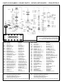
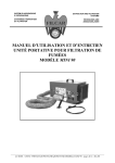
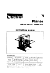
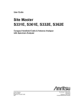
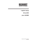
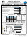
MANUALE USO E MANUTENZIONE
Use and maintenance manual
NOTICE D’UTILISATION et d’entretien
GEBRAUCHSANWEISUNG
12
POMPE E KIT PER DISTRIBUZIONE OLIO
POMPES ET KIT POUR DISTRIBUTION D’HUILE
PUMPS AND KITS FOR OIL DISTRIBUTION
PUMPEN UND GERÄTESETS ZUR ÖLABGABE
CARATTERISTICHE TECNICHE / TECHNICAL CHARACTERISTICS
CARACTERISTIQUES TECHNIQUES / TECHNISCHE EIGENSCHAFTEN
-
-
-
-
-
-
-
-
-
Rapporto - Ratio - Rapport - Verhältnis................................ 6:1............ 4:1
Pressione aria - Air pressure
Pression air - Luft-Druck..................................................4-8 bar......4-8 bar
Raccordo entrata aria - Air inlet connection
Raccord entrée air - Luftanschluss.................................... 1/4”G........ 1/4”G
Raccordo entrata olio - Oil inlet connection
Raccord entrée huile - Öl Einlassanschlussstück................. 1”G........... 1”G
Raccordo uscita olio - Oil outlet connection
Raccord sortie huile - Öl Auslaßanschlußstück................. 1/2”G........ 1/2”G
Portata a uscita libera - Delivery at free outlet
Débit à sortie libre - Durchlauf mit freiausgang...... (6 bar) 13 l/1’....... 20 l/1’
Lunghezza camera - Suction tube length
Longueur canne - Saugrohr-Länge (A).......................... 175 mm.... 175 mm
Diametro pescante - Suction tube diameter
Diamètre canne - Saugrohr-Durchmesser (B)...................... 42 mm...... 50 mm
Ghiera fissaggio - Ring for fixing
Embout de fixation - Fixierungring....................................... 2” G.......... 2” G
Codice - Code
Code - Art. Nr.
Fusti - Drums
Fûts - Fässer
L
(mm)
OD-PP-4480
Murale
Wall mounted
Mural
Wandmontage
175
OD-PP-4482
50-60 Kg
730
OD-PP-4484
180 - 200 Kg
940
OD-PP-4486
Murale
Wall mounted
Mural
Wandmontage
175
OD-PP-4488
50 - 60 Kg
730
OD-PP-4490
180 - 200 Kg
940
L=LP+175
PESCANTi RIGIDi / rigid pipe
canne rigide / starren SAUGROHR
Codice - Code
Code - Art. Nr.
L (mm) LP (mm)
Applicazione
Application
Application
Anwendung
OD-ACC-730
730
555
Fusti/Drums
50/60 Litri/Litres
OD-ACC-940
940
765
Fusti/Drums
200 Litri/Litres
OD-ACC-1130
1130
955
Cisterna/Tank
1000 Litri/Litres
OD-ACC-1500
1500
1325
Cisterna/Tank
1500 Litri/Litres
OD-ACC-2160
2160
1985
Cisterna/Tank
installaZIONE con
PESCANTE rigido
installation with
rigid pipe
installation avec
CANNE rigide
Installation mit
starren saugrohr
• Il pescante è adatto per l’applicazione diretta sul raccordo di aspirazione della pompa.
• The rigid pipe is suitable for direct application on the suction connector of the pump.
• La canne est adaptée à une application directe à le raccord d’aspiration de la pompe.
• Der Saugrohr ist geeignet für die direkte Anwendung an der Sauganschluss der Pumpe.
Installazione con
tubo flessibile
installation with
flexible hose
installation avec
tuyau flexible
Installation Mit
flexiblen SCHLAUCH
KIT MURALE PER DISTRIBUZIONE OLIO / WALL KIT for OIL DISTRIBUTION
KIT mural pour DISTRIBUTION D’HUILE / WANDMONTAGE SET FÜR Ölverteilung
OD-PP-4486
OD-PP-4490
OM-FA-7303
7256
OD-ACC-2550
Codice - Code
Code - Art. Nr.
LP (mm)
LG (mm)
OD-PC-1035
1100
1035
OD-PC1265
1325
1260
OD-PC-1660
1725
1660
OD-PC-1920
1985
1920
LG max = LP - 65 mm
ODTF-G1L02-MM
OD-ACC-1275
OD-KIT-2436
OD-KIT-2432
filtro - filter
filtrer - filtern
FILCAR S.p.a.
Via G. Balla, 18 - 42040 Cella (Reggio Emilia) ITALY
Tel. +39/0522.941881 - Fax +39/0522.942291
www.filcar.eu - [email protected]
I
CARATTERISTICHE TECNICHE
GB
TEchnical characteristics
-Pompe pneumatiche a DOPPIO EFFETTO per la distribuzione d’olio.
- Il rapporto di compressione della pompa OD-PP-4480 é
4:1, della OD-PP-4486 é 6:1. Questo significa che l’olio
esce dalla pompa ad una pressione 4 volte o 6 volte
superiore alla pressione di entrata dell’aria compressa.
Per evitare di provocare danni é vietato superare la
pressione massima consentita dell’aria compressa.
- Quando si opera a contatto con il prodotto da pompare é
necessario indossare guanti ed indumenti protettivi. Consultare la scheda di sicurezza del prodotto.
- Chiudere sempre l’aria e scaricare l’olio in pressione prima
di lavorare sulla pompa o sull’impianto.
-Double acting pneumatic pumps suitable to oil distribution.
- The pressure ratio of the pump OD-PP-4480 is 4:1,of the
pump OD-PP-4486 is 6:1 This means that oil comes out
of the pump at a pressure 4 or 6 times higher than the inlet
pressure of compressed air. To prevent accidents from
happening do not exceed the max. permissible pressure
of compressed air.
- When operating at contact with the product, wear gloves
and protective clothing. Consult the safety table of the
product.
- Always close the air and relieve the oil in pressure before
any work to the pump or to the system is carried out.
Il motore pneumatico é prelubrificato con
grasso al silicone. Se la pompa viene usata
in modo normale è sufficiente applicare un
regolatore di pressione.
- Per servizi continuativi, consigliamo di applicare sulla
pompa un gruppo FRL filtro-regolatore-lubrificatore.
Regolare al massimo 1 goccia ogni 10 minuti. Utilizzare
olio per utensili pneumatici oppure olio motore SAE
10. Non usare olio sintetico o altri tipi di olio.
- In impianti centralizzati le pompe possono essere alimentate con aria essiccata montando un lubrificatore
sulla rete oppure sulla pompa.
The pneumatic motor is pre-lubricated with
silicon grease. When the pump is used under
normal operating conditions, it is sufficient to
fit an air regulator.
-For continuative services, we recommend you to fit a FRL
filter, pressure regulator, lubricator on the pump. Set max.
1 drop every 10 minutes. Use air tool oil or motor oil
SAE 10. Synthetic oil or other oils must not be used.
-In centralized systems, pumps can be feeded by dry air
by mounting a lubricator on the pipework or on the pump.
F CARACTERISTIQUES TECHNIQUES
- Pompes pneumatiques à double effet pour la distribution d’huile.
- Le rapport de compression de la pompe OD-PP-4480 est
4:1 et de la pompe OD-PP-4486 est 6:1. Cela signifie
que l’huile sort de la pompe avec une pression 4 et 6
fois plus haute que la pression d’entrée de l’air comprimé. Pour éviter de provoquer des dommages, il est
interdit de dépasser la pression maxi. consentie de l’air
comprimé.
- Quand on travaille au contact du produit à pomper, il faut
porter les gants et les vêtements protecteurs. Consulter
la carte de sécurité du produit.
- Fermer toujours l’air et décharger l’huile en pression
avant d’effectuer n’importe quel travaille sur la pompe
ou sur l’installation.
Le moteur pneumatique est pre-lubrifiqué
avec de graisse au silicon. Si la pompe est
utilisée en conditiones normales, il suffit d’appliquer un régulateur de pression.
- Pour des services continus on conseille d’appliquer un
FRL, filtre, régulateur de pression, graisseur sur la pompe. Régler au maximum 1 goutte chaque 10 minutes.
Utiliser d’huile pour outils pneumatiques ou d’huile
moteur SAE 10. Ne pas utiliser d’huile synthétique
ou n’importe quel types d’huile different de ceux
conseillés.
- Dans les installations centralisées les pompes peuvent
être alimentées par air séche en montant un régulateur
sur la ligne ou sur la pompe.
D
TECHNISCHE EIGENSCHAFTEN
- Pneumatische Pumpen mit ZWEIFACHEM EFFEKT,
geeignet für die verteilung von Öl.
- Der Verdichtungsgrad der OD-PP-4480 Pumpe beträgt
4:1, ist der OD-PP-4486 6:1. Dies bedeutet, dass das
Öl aus der Pumpe mit einem Druck austritt, der 4 und
6 mal größer als der Eintrittsdruck der Druckluft ist. Zur
Verhinderung von Schäden, ist ein Überschreiten des
maximal zulässigen Drucks der Druckluft verboten.
- Beim Arbeiten in Berührung mit dem zu pumpenden Produkt, sind Schutzhandschuhe und -kleidung erforderlich.
Dazu Sicherheitstabelle des Produktes konsultieren.
- Druckluftzufuhr schließen und das unter Druck stehende Öl ablassen, bevor auf der Pumpe oder der Anlage
gearbeitet wird.
Der Druckluftmotor ist mit Silikonfett vorgeschmiert. Wird die Pumpe unter normalen
Bedingungen betrieben, reicht der Einbau
eines Druckreglers aus.
- Bei Dauerbetrieb, wird der Einbau einer FRS-Gruppe
aus Filter-Regler-Schmierer empfohlen. Auf maximal
1 Tropfen alle 10 Minuten einstellen. Öl für Druckluftwerkzeuge oder Motoröl SAE 10 verwenden. Kein
synthetisches Öl oder andere Ölsorten verwenden.
- Bei Sammelschmieranlagen können die Pumpen mit
Trockenluft gespeist werden, indem ein Schmierer auf
dem Verteilernetz oder auf der Pumpe montiert wird.
I
USO E MANUTENZIONE
- La pompa si mette in funzione automaticamente azionando la pistola.
ATTENZIONE! Per ragioni di sicurezza
é obbligatorio:
- Indossare i guanti ed indumenti protettivi quando si effettuano
operazioni.
- Togliere sempre l’alimentazione dell’aria quando si termina il turno
di lavoro o si effettuano operazioni di manutenzione.
- Controllare periodicamente che i raccordi siano ben serrati per impedire che eventuali perdite facciano funzionare la pompa a vuoto.
- Sostituire i tubi flessibili quando sono danneggiati o usurati.
Per evitare danni e malfunzionamenti della pompa:
- Quando si sostituisce il fusto non
appoggiare mai la pompa sul terreno.
- Pulire accuratamente le parti che
sono venute a contatto di eventuali
impurità.
- Proteggere il prodotto da pompare
dalla caduta o dall’introduzione di
corpi estranei.
AVARIE E RIMEDI
Di seguito sono elencate alcune anomalie di facile risoluzione. Se l’anomalia persiste o in presenza di altre disfunzioni non effettuare interventi di smontaggio sulla pompa, ma interpellare il rivenditore.
La pompa non si avvia e perde -Cursore 7483 bloccato...................Spingere a fondo il pulsante di ripristino 7504 (RESET)
aria dal silenziatore:
-Cursore 7483 non scorre . .......... Ingrassare o sostituire il cursore o applicare lubrificatore
-Guarnizioni 7482 usurate................................................................Sostituire le guarnizioni
La pompa funziona a vuoto e -Fusto vuoto................................................................................Controllare il livello dell’olio
non eroga olio:
-Bolla d’aria nel tubo di aspirazione.......Scollegare il tubo di mandata e spurgare la pompa
La pompa ogni tanto dà qual- -Possibile perdita di fluido nell’impianto.................... Controllare i raccordi, i tubi e la pistola
che colpo a vuoto:
-Usura del gruppo pompante.................... Intervento di assistenza. Contattare il rivenditore
Per smontare il cursore 7483 basta sfilare i due tappi 7478 e 7479 dopo aver tolto la clip cod.7477 e con un cacciavite farlo
fuoriuscire dalla sua sede. Controllare le guarnizioni, ingrassare il cursore con grasso al silicone o se necessario sostituirlo.
GB
OPERATION AND MAINTENANCE
- The pump starts up automatically when operating the gun.
WARNING! FOR REASONS OF SAFETY YOU MUST:
Wear gloves and protective clothing when carrying operations.
- Always close the air supply when the premises are unattended or
any maintenance is carried out.
- Periodically check that connections are strongly tightened to prevent
the idling of the pump due to leakings.
- Replace the flexible hoses when damaged or worn.
TO AVOID DAMAGES AND BAD
WORKING OF THE PUMP:
- When changing drums keep the
pump off the floor.
- Clean carefully those parts which
have been possibly contaminated
by dirt.
- Protect the fluid from falls and from
dirt.
TROUBLE SHOOTING
Here under some working troubles easily solvable are listed. In case the problem persists or it is not among the ones here listed
DO NOT CARRY OUT DISASSEMBLING INTERVENTIONS ON THE PUMP but contact our sales centres.
The pump does not start up
and and releases air from
silencers:
- Slider 7483 locked............................................................Push the button 7504 (RESET)
- Slider 7483 not slide................................... Grease or replace the slider or fit a lubricator
- Seals 7482 worn ................................................................................. Replace the seals
The pump idles and does not
deliver oil:
- Empty drum................................................................................................ Check oil level
- Air bubble in the suction pipe................. Disconnect the delivery hose and drain the pump
Sometimes the pump idles:
- Possible fluid loss in the system........................ Check connections, hoses, and the gun
- The pumping group is worn......... Qualified assistance required. Contact our sales centres
To disassemble the slider 7483, unthread the two plugs 7478 and 7479 after removing the clip code 7477 and then by a
screwdriver make it get out from its seat. Check the seals, grease the slider with silicon grease or, if necessary, replace it.
F
UTILISATION ET ENTRETIEN
- La pompe se met en fonction automatiquement en actionant la poignée.
ATTENTION! POUR DES RAISONS DE SECURITE IL FAUT:
Porter les gants et les vêtements protecteurs quand on effectue
des operations.
- Fermer toujours l’alimentation de l’air quand on termine le service et
avant d’effectuer n’importe quel travail d’entretien.
- Contrôler de temps en temps que les raccords soient bien serrés
pour éviter que d’éventuelles pertes faissent fonctionner la pompe à
vide.
- Remplacer les tuyaux flexibles dès qu’ils sont damagés ou qu’ils
montrent des marques d’usure.
POUR EVITER UN MAUVAIS FONCTIONNEMENT ET DES DAMAGES
DE LA POMPE:
- Ne jamais appuyer la pompe sur
le carrelage en remplacant le fût
d’huile.
- Nettoyer avec soin les composants
qui sont venus au contact d’eventuelles impuretés.
- Proteger le produit à pomper des
chutes et de l’introduction de corps
étrangers.
ANOMALIES ET REMEDES
Ci-après il y a une liste d’anomalies faciles à resoudre. Au cas où le problème persisterait ou en présence de n’importe quel problème different de ceux
indiqués ci-dessus NE PAS EFFECTUER D’INTERVENTIONS DE DESASSEMBLAGE SUR LA POMPE mais appeler le revendeur.
La pompe ne se met pas en - Le courseur 7483 est bloqué.....................Presser jusqu’au fond le bouton 7504 (RESET)
fonction et pert air du silen- -Le curseur 7483 ne glisse pas ........... Graisser ou remplacer le curseur ou appliquer un lubrificateur
cieux:
-Kit joints 7482 usuré........................................................................... Remplacer les joints
La pompe fonctionne à vide
et ne distribue pas de huile:
-Fût vide....................................................................................... Contrôler le niveau d’huile
- Bulle d’air dans le tuyau d’aspiration...........Débranchez le tuyau de distribution et purger la pompe
La pompe de temps en temps
fonctionne à vide:
-Possible perte de huile dans le système................ Contrôler les raccords, les tuyaux et la poignée
-Le group de pompage est usuré............ Intervention d’assistence.Contacter le revendeur
Pour retirer le curseur 7483 il suffit de tirer les bouchons 7478 et 7479 après avoir enlevé le clip cod.7477 et avec un tournevis
le faire sortir de son siège. Vérifier les joints, graisser le curseur avec de la graisse de silicone ou remplacer si nécessaire.
D
BETRIEB UND WARTUNG
- Der Betrieb der Pumpe erfolgt automatisch beim Betätigen der Ölpistole.
ACHTUNG, AUS SICHERHEITSGRÜNDEN IST ES
PFLICHT:
- Schutzhandschuhe und-kleidung zu tragen, sobald Schmierarbeiten ausgeführt werden.
- Druckluftzufuhr unterbrechen, sobald die Arbeitsschicht beendet
wird oder Wartungsarbeiten ausgeführt werden.
- Anschlüsse regelmäßig auf guten Sitz prüfen, um zu verhindern,
dass gegebenenfalls Lecks die Pumpe leerlaufen lassen.
- Schläuche ersetzen, sobald sie Schäden oder Verschleiß zeigen.
Z U R V O R B E U G U NG GEGEN
SCHÄDEN ODER FEHLFUNKTION
DER PUMPE:
- Beim Auswechseln des fasses, die
Pumpe nie auf dem Boden abstellen.
- Alle Teile, die mit möglichen Verunreinigungen in Berührung gekommen sind,
gründlich säubern.
- Das zu pumpende Produkt vor hineinfallenden oder eindringenden Fremdkörpern schützen.
STÖRUNGEN UND IHRE BEHEBUNG
Nachfolgend werden einige leicht zu behebende Störungen aufgeführt. Bei Fortdauer der Störung oder bei Auftreten anderer Fehlfunktionen KEINE EINGRIFFE AUF DER PUMPE VORNEHMEN ODER DIESE AUSEINANDERBAUEN, sondern den Händler rufen.
Die Pumpe wird nicht in Gang - Der Schieber 7483 ist blockiert................................Rückstellknopf (7504) voll eindrücken
gesetzt und verliert Luft aus - Der Schieber 7483 gleitet nicht..........Schmieren oder Schieber austauschen oder Schmierer einbauen
den Schalldämpfern
- Verschleiß der Dichtungpaket 7482...............................................Dichtungpaket ersetzen
Pumpe läuft leer und gibt kein - Leere Fässer.......................................................................................Ölstand kontrollieren
Oel ab
- Luftblase in der Saugleitung............... Ziehen Sie den Druckschlauch und entleeren Sie die Pumpe
Pumpe läuft hin und wieder - Möglicherweise leckt Oel aus der Anlage............Anschlüsse, Schläuche und Fettpresse überprüfen
leer
- Verschleiß des Pumpenaggregats...............Eingriff und Service. Bitte an den Händler wenden
Um den Cursor 7483 entfernen Ziehen Sie einfach den Stecker 7478 und 7479 nach dem Entfernen des Clips cod.7477 und mit ein Schraubenzieher um sie auswerfen seines Sitzes. Überprüfen Sie die Dichtungen, Fett den Cursor mit Silikonfett oder bei Bedarf ersetzen.
PARTI DI RICAMBIO / SPARE PARTS / PIECES DETACHEES / ERSATZTEILE
7481CPL Distributore completo - Complete distributor Distributeur complet - Komplett Verteiler
(7259A+7271+7275+7280+7454+7477+7478+7479
+7480+7481+7482+7483+7503+7504+7505)
SEALS PACKET
CODE ITALIANO
ENGLISH
CODE ITALIANO
ENGLISH
PISTON D.32 - 4:1
BALL SEAT
D.37-30 PISTON - 6:1
M50 MUFF - 4:1
D.45-37 PISTON - 4:1
CHAMBER L=160 - 6:1
CHAMBER L=160 - 4:1
D.1/2” BONDED WASHER
D.28-40 PU SEAL - 6:1
D.32-42 PU SEAL - 4:1
O-RING 115 (11.91x2.62)
WASHER D.12x20
BELLEVILLE WASHER D.10x20
D.27/32” STEEL BALL (D.21.4)
SUCTION CONNECTION - 4:1
SUCTION CONNECTION - 6:1
SILENCER
CLIP FOR PLUG
PLUG WITH HOLE
PLUG WITHOUT HOLE
COVER FOR FILTER
DISTRIBUTOR
JOINTS PACKET
SLIDER
O-RING 2031 (7,66x1,78)
AIR CYLINDER
O-RING 19x1
PUSH BOTTON
PU BUFFER
AIR PISTON
ASSEMBLED PISTON
0016
0044
0135
7212
7220
7226
7256
7257
7259A
7260
7270
7271
7272
7275
7277
7280
7281
7284A
7285
7286
7287
7288
7289
7290
7291
7326
7327
7328
7329
7330
DADO M10.................................... M10 NUT
DADO FR M6................................ M6 FR NUT
RONDELLA D.8x24....................... WASHER D.8x24
RACCORDO M10......................... M10 FITTING
TIRANTE L=40.............................. TIE ROAD L=40
MOLLA D.35.................................. SPRING D.35
GHIERA D.42 - 6:1........................ RING D.42 - 6:1
GHIERA D.50 - 4:1........................ RING D.50 - 4:1
RIDUZIONE M+F1/4”.................... M+F1/4” FITTING
SPINA ELASTICA D.3x14............. D.3x14 PIN
TAPPO IN NYLON ....................... NYLON PLUG
GUARNIZIONE D.12-18 PU......... D.12-18 PU SEAL
GUARNIZIONE D.65 PU............... D.65 PU SEAL
SEEGER ZJ 22............................. TAB WASHER ZJ 22
VITE FR M6x51............................. M6X51 SCREW
OR 64x1.5..................................... O-RING 64x1.5
OR 2.84x2.62................................ O-RING 2.84x2.62
GUARNIZ. D.30-38 PU - 6:1.........D.30-38 PU SEAL - 6:1
GUARNIZ. D.38-46 PU - 4:1......... D.38-46 PU SEAL - 4:1
OR 3137 (34.6x2.62) - 6:1............O-RING (34.6x2.62) - 6:1
OR 3168 (42.52x2.62) - 4:1.......... O-RING (45.52x2.62) - 4:1
PIASTRINA PER GHIERA............ BRACKET FOR RING
VITE AD ALETTE M6x20.............. M6x20 WINGED SCREW
GHIERA COMPLETA - 6:1............ COMPLETE RING - 6:1
GHIERA COMPLETA - 4:1............ COMPLETE RING - 4:1
MANICOTTO M42 - 6:1................ M42 MUFF - 6:1
VITE DOPPIA 1/2” G..................... DOUBLE SCREW 1/2” G
GHIERA - 6:1................................ RING - 6:1
GHIERA - 4:1................................RING - 4:1
PISTONE D.28 - 6:1...................... PISTON D.28 - 6:1
7331
7332
7333A
7335
7336
7338A
7339A
7340
7341
7342
7343
7344
7345
7346
7350
7351
7454
7477
7478
7479
7480
7481
7482
7483
7488
7502
7503
7504
7505
7515
7516
PISTONE D.32 - 4:1........................
SEDE SFERA..................................
PISTONE D.37-30 - 6:1..................
MANICOTTO M50 - 4:1..................
PISTONE D.45-37 - 4:1..................
CAMERA L=160 - 6:1......................
CAMERA L=160 - 4:1......................
RONDELLA BONDED D.1/2”..........
GUARNIZ. D.28-40 PU - 6:1...........
GUARNIZ. D.32-42 PU - 4:1...........
OR 115 (11.91x2.62).......................
RONDELLA D.12x20.......................
MOLLA A TAZZA D.10x20 ..............
SFERA D.27/32” (D.21.4)................
RACC. ASPIRAZIONE - 4:1............
RACC. ASPIRAZIONE - 6:1............
SILENZIATORE...............................
CLIP PER TAPPO...........................
TAPPO FORATO.............................
TAPPO SENZA FORO....................
CUFFIA COPRI FILTRO.................
DISTRIBUTORE.............................
PACCO GUARNIZIONI...................
CURSORE......................................
OR 2031 (7,66x1,78).......................
CILINDRO MOTORE......................
OR 19x1..........................................
PULSANTE RESET........................
TAMPONE PU.................................
PISTONE MOTORE........................
PISTONE ASSEMBLATO................
7489
Kit guarnizioni ricambio per pompe 4:1
Kit of spare seals for pumps 4:1
Kit joints de rechange pour pompes 4:1
Ersatzdichtungen für pumpen 4:1
7490
Kit guarnizioni ricambio per pompe 6:1
Kit of spare seals for pumps 6:1
Kit joints de rechange pour pompes 6:1
Ersatzdichtungen für pumpen 6:1
(7271+7272+7275+7280+7281+7285+7287+7342+7343+7482+7488+7503)
(7271+7272+7275+7280+7281+7284A+7286+7341+7343+7482+7488+7503)
FILCAR S.p.a.
Via G. Balla, 18 - 42040 Cella (Reggio Emilia) ITALY
Tel. +39/0522.941881 - Fax +39/0522.942291
www.filcar.eu - [email protected]
I
DICHIARAZIONE DI CONFORMITA' CE
La sottoscritta FILCAR S.p.a. con sede a Cella in Via G. Balla,18, dichiara sotto la propria esclusiva responsabilità che
le pompe pneumatiche per olio
modello: OD-PP-4480; OD-PP-4482; OD-PP-PP-4484; OD-PP-4486; OD-PP-4488; OD-PP-4490
serie / anno di costruzione: riferirsi alla marcatura apposta sulla camera della pompa
sono conformi alla Direttiva macchine 2006/42/CE
Norme armonizzate applicate:
-
UNI EN ISO 12100-1:2010 - UNI EN ISO 12100-2:2010 Sicurezza del macchinario - Concetti fondamentali, principi
generali di progettazione
-
UNI EN 13857:2008 Sicurezza del macchinario - Distanze di sicurezza per impedire il raggiungimento di zone
pericolose con gli arti superiori e inferiori
La persona autorizzata a costituire il fascicolo tecnico è il Sig. Menozzi Paolo in qualità di rappresentante legale.
GB
DECLARATION OF CE CONFORMITY
The undersigned FILCAR S.p.a. based in Cella Via G. Balla,18, hereby states under its own responsibility that the
pneumatic pumps for oil
model: OD-PP-4480; OD-PP-4482; OD-PP-PP-4484; OD-PP-4486; OD-PP-4488; OD-PP-4490
serie / year of production: refer to the marking affixed to the chamber of the pump
are in conformity with the Machinery directive 2006/42/CE
Harmonized rules applied:
-
UNI EN ISO 12100-1:2010 - UNI EN ISO 12100-2:2010 Safety of machinery - Basic concepts, general principles
for design
-
UNI EN 13857:2008 Safety of machinery - Safety distances to prevent hazard zones being reached by upper and
lower limbs
The person authorized to compile the technical file is Menozzi Paolo as legal representative.
F
DéCLARATION DE CONFORMITé
Le soussigné FILCAR S.p.a. située à Cella Via G. Balla,18, déclare sous sa responsabilité que les pompes pneumatiques à huile
modèle: OD-PP-4480; OD-PP-4482; OD-PP-PP-4484; OD-PP-4486; OD-PP-4488; OD-PP-4490
série / année de construction: se référer au marquage apposé à la chambre de pompe
sont conformes à la Directive Machine 2006/42/CE
En outre, les règles harmonisées suivantes on été appliquées :
-
UNI EN ISO 12100-1:2010 - UNI EN ISO 12100-2:2010 Sécurité des machines – Concepts fondamentaux, principes généraux de projet
-
UNI EN 13857:2008 Sécurité des machines – Distances de sécurité empêchant les membres supérieurs et inférieur d’atteindre les zones dangereuses.
La personne autorisée à constituer le dossier technique est Menozzi Paolo en qualité de représentant légal.
D
KONFORMITÄTSERKLÄRUNG
Der Unterzeichnende FILCAR S.p.a. mit Sitz in Cella Via G. Balla,18, erklärt in alleiniger Verantwortung, dass die
Druckluftpumpen von Öl
Modelle: OD-PP-4480; OD-PP-4482; OD-PP-PP-4484; OD-PP-4486; OD-PP-4488; OD-PP-4490
Serie / Baujahr: beziehen sich auf die Inzision auf der Pumpenkammer
Sie sind getreu der Maschinenrichtlinien 2006/42/CE
Angewandte harmonisierte Normen:
-
UNI EN ISO 12100-1:2010 - UNI EN ISO 12100-2:2010 Sicherheit von Maschinen - Grundbegriffe, allgemeine
Gestaltungsleitsätze
-
UNI EN ISO 13857:2008 Sicherheit von Maschinen - Sicherheitsabstände gegen das Erreichen von Gefährdungsbereichen mit den oberen und unteren Gliedmaßen
Die berechtigte Person das technische Heft zu bilden ist Herr Menozzi Paolo, als gesetzlicher Vertreter.
Cella, 31.05.12
Menozzi Paolo
Amministratore delegato