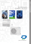
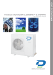
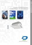
Download d.12000-18000-24000sp-invplus serie 2011
Transcript
DC Inverter R410A Sistemi per la climatizzazione M A NUA LE D’ US O BLU ICE FLOOR D.12000SPINV PLUS - D.18000SPINV PLUS D.24000SPINV PLUS D.12000SPINV PLUS - D.18000SPINV PLUS - D.24000SPINV PLUS Linea commerciale D.12000 - D.18000 - D.24000 SPINV PLUS DC Inverter R410A 1 - CONSIDERAZIONI SULLA SICUREZZA Grazie per avere acquistato un nostro prodotto. Leggere attentamente questo manuale prima dell’utilizzo conservandolo per riferimenti futuri. Prestare particolare attenzione ai seguenti simboli: 2 ATTENZIONE! : indica che un funzionamento improprio potrebbe causare morte o lesioni. ATTENZIONE! : indica che un funzionamento improprio potrebbe causare lesioni o danneggiamenti. ATTENZIONE ! • Questa unità dovrebbe essere utilizzata negli uffici, ristoranti, abitazioni o luoghi simili. • Per l’installazione selezionare un luogo adatto. Un’installazione non corretta potrebbe causare perdite d’acqua, folgorazioni o incendi. • Installare l’unità in un luogo adatto a sopportarne il peso. In caso contrario il condizionatore potrebbe cadere e causare lesioni o morte. • Per assicurare un corretto drenaggio, il condotto di drenaggio deve essere installato appropriatamente in base alle istruzioni. Prendere le dovute misure per la conservazione del calore per prevenire la condensazione. Un’impropria installazione dei tubi potrebbe causare perdite e bagnare gli oggetti nella stanza. • Non usare sostanze infiammabili, esplosive, o velenose vicino al condizionatore. • In caso di problemi (per esempio odore di bruciato), togliere immediatamente l’alimentazione del condizionatore. • Mantenere il flusso d’aria per evitare mancanze d’ossigeno nella stanza. • Non inserire oggetti nelle griglie di entrata e di uscita dell’aria. • Non inserire o togliere il cavo dell’alimentazione direttamente per accendere o spegnere il condizionatore. • Controllare in modo costante se i supporti si rovinano dopo un lungo periodo. • Non modificare il condizionatore. Contattare il venditore o professionisti per riparare o spostare il condizionatore. • L’applicazione non deve essere installata nelle lavanderie. • Prima dell’installazione, controllare l’alimentazione e controllare che sia conforme alla categoria sulla targhetta. Controllare anche l’ interruttore di sicurezza. • Prima dell’uso, controllare che i cavi, i condotti di drenaggio e i tubi siano connessi correttamente in modo da eliminare i rischi di perdite d’acqua o di refrigerante, incendi e folgorazioni. • L’alimentazione deve prevedere una sicura messa a terra per evitare il rischio di folgorazione. Non connettere il cavo di massa al tubo del gas e dell’acqua, all’impianto d’illuminazione o alla linea del telefono. • Una volta acceso, il condizionatore non deve essere spento per almeno 5 minuti, altrimenti l’olio del compressore potrebbe danneggiarsi. • Non far usare il condizionatore ai bambini. • Non toccare il condizionatore con le mani bagnate. • Disconnettere l’alimentazione prima di pulire il condizionatore e prima di reinserire i filtri. • Disconnettere l’alimentazione se il condizionatore rimane spento per un lungo periodo. • Non esporre il condizionatore a elementi corrosivi come acqua o umidità. MANUALE D’USO Linea commerciale • Non camminare e non appoggiare nessun oggetto sul condizionatore. • Dopo l’installazione, il condizionatore deve essere testato da professionisti. • Se il filo dell’alimentazione è danneggiato, deve essere sostituito da una persona qualificata, per evitare pericoli. • L’applicazione deve essere installata in base ai regolamenti nazionali vigenti. • La temperatura del circuito refrigerante è elevata, tenere lontani i cavi di interconnessione dai tubi di rame. 2. LCD Displaying Part 2 - DISPLAY DEL CONTROLLO A MURO 2. Displaying Part Fig.1 Outline of wired controller 2.1 LCD Display of Wired Fig.1 controller Outline of wired controller 2.1 LCD Display of Wired controller Fig.2 LCD display Fig.2 LCD display Displaying Part Displaying Part 3 3 3 D.12000SPINV PLUS - D.18000SPINV PLUS - D.24000SPINV PLUS Linea commerciale Istruzioni del Display LCD N. DESCRIZIONE FUNZIONE 1 Swing Funzione swing 2 Aria* Funzione scambio aria 3 Sleep Funzione notturna attiva 4 Running mode Funzionamento automatico 5 Cool Funzione raffreddamento 6 Dry Funzione deumidificazione 7 Fan Funzione ventilazione 8 Heat Funzione riscaldamento 9 Defreost Funzione sbrinamento attivo 10 Gate control card* Porta di controllo carte 11 Lock Blocco 12 Shield Comando a distanza 13 Turbo Funzione turbo attiva 14 Memory 15 Twinkle 16 Save Modalità risparmio energetico 17 Temperature Temperatura ambiente 18 E-Heater* Attivazione del gruppo elettrico di supporto al riscaldamento 19 Blow Attivazione funzione Blow 20 Timer Visualizzazione dell’impostazione del timer 21 Quiet Funzione Quiet attiva (silenziosa) Memoria (l’unità interna tiene in memoria l’ultima funzione utilizzata) Lampeggia quando l’unità è in funzione senza l’utilizzo dei pulsanti (telecomando) Nota: le funzioni con “*” non sono predisposte per tutti i modelli. 4 MANUALE D’USO Linea commerciale 3 - COMANDI 3. Buttons Silk Screen of Buttons N. 1 DESCRIZIONE No. Enter/cancel 2 6 Fig.3 Silk screen of buttons Instruction to Function of Buttons Table.2 FUNZIONE DEI TASTI Description Function of Button 1 Enter/cancel 2 Ÿ 6 ź 3 Fan 4 Mode 5 Function 3 Fan 4 Mode 5 Function 7 Timer 7 Timer 8 On/off 8 ON/OFF 4 Mode and 2Ÿ 2Ÿ and 6ź Buttons ķ Function selection and canceling; Selezione e cancella le funzioni ĸ PressTenere it for 5spremuto to enquiryper the 5outdoor ambient la temperature. sec mostra temperatura esterna ķ Running temperature setting of indoor unit, range :16㨪 30qC ĸTimerSelezione setting, range:0.5-24hr della temperatura: 16 – 30 °C ĹSwitch over between quiet/auto quiet. del timer: 0,5 24 H Setting Selezione of high/middle/low/auto fan– speed Commutazione stati (es. quiet / auto quiet) Selezione della ventilazione: alta, media, bassa, auto Switchover among these functions of Seleziona la modalità di funzionamento: cool, heat, air/sleep/turbo/save/e-heater/blow/quite fan, dry Passaggio tra le seguenti funzioni: air/sleep/turbo_/ Timer setting save/e-heater/blow/quiet Setting of cooling/heating/fan/dry mode of indoor unit Selezione Turn on/off indoor del unit Timer Memory function Press Mode and l’accensione/spegnimento Ÿfor 5s under off state of the unit to Selezione enter/cancel key memory function (If memory is set, indoor unit will resume original setting state after power failure and then power recovery. If not, indoor unit is defaulted to be off after power recovery. Memory function is defaulted to be off before outgoing.) Lock Upon startup of the unit without malfunction or under off state of the unit, press Ÿ ź key at the same time for 5s in to lock state. In this case, any other buttons won’t respond the press. Repress Ÿ ź key for 5s to quit lock state. 5 5 D.12000SPINV PLUS - D.18000SPINV PLUS - D.24000SPINV PLUS Linea commerciale 4 - INSTALLAZIONE DEL PANNELLO DI CONTROLLO Fig.4 - Schema controllo 4. d’installazione Installationdel of pannello Wired di Controller 1. 2. 3. 4. 5. Predisposizione per le prese elettriche a muro Fig.4 Sketch for Installation of Wired Controller Base di fissaggio del pannello di controllo Viti 4 X 25 Pannello No.di controllo 1 2 3 4 Viti 2,2 X 6,5 Soleplate of Screw M4X25 Front panel of Description Socket’s base controller box installed in controller the wallpunti durante l’installazione Nota: fare attenzione ai seguenti 1. 2. 3. 4. 5. 5 Screw ST2.2X6.5 Fig.4: Sketch for Installation of Wired Controller. Pay attention to the following items during Assicurarsi di togliere l’alimentazione prima di procede con qualsiasi operazione installation of wired controller: Predisporre 4 fili nella predisposizione per la presa elettrica per collegarsi successivamente al retro del pannello 1. Cut power supply ofdiheavy-current wire embedded in mounting in the wall before4 x 25) Fissare la off base del pannello controllo sulla predisposizione (utilizzarehole le viti in dotazione Collegare i 4 fili precedentemente pannello di controllo installation. It is prohibited to predisposti perform the sul whole procedure with electricity. Fissare il pannello di twisted controllo alla propria base (utilizzare le vitimake in dotazione 6,5) 2. Pull out 4-core pair line in mounting hole and then it through2,2 thexrectangle hole at the back of controller’s soleplate. 3. Joint the controller’s soleplate on wall face and then fix it in mounting hole with screws M4X25. 4. Insert the 4-core twisted pair line through rectangle hole into controller’s slot and buckle the front ATTENZIONE ! panel and soleplate of controller together. 5. At last, fix the controller’s front panel and soleplate with screws ST2.2X6.5. Durante la connessione dei fili, porre attenzione alle seguenti istruzioni per evitare interferenze e quindi disturbi sul vostro prodotto: Caution: During connection of wirings, pay special attention to the following items to avoid interference of 1. Per garantire un corretto funzionamento del prodotto le linee di segnale e le linee del pannello di controllo devono electromagnetism to unit and even failure of it. essere separate 2. 1. To ensure normal communication of the unit, signal line and wiring (communication) of wired Se l’unità viene installata in posti dove ci sono delle interferenze di elettromagnetismo, potrebbe esserci dei controller should be separate from power cord and indoor/outdoor connection lines. The distance problemi nell’utilizzo del prodotto between them should be kept 20cm in min. 2. If the unit is installed at the place where there is interference of electromagnetism, signal line and wiring (communication) of wired controller must be shielded by twisted pair lines. Installation of Wired Controller 6 6 5. Instruction to Operation MANUALE D’USO Linea commerciale 5.1 On/Off Press On/Off button to turn on the unit. Repress this button to turn off the unit. 5 - FUNZIONI The state shown in Fig.5 indicates off-state of the unit after energizing 5. Note: Instruction to Operation The state shown in Fig.6 indicates on-state of the unit after energizing. 5.1 - Accensione/spegnimento 5.1 On/Off Press On/Off button to turn on the unit. Repress this button to turn off the unit. Note: The state shown in Fig.5 indicates off-state of the unit after energizing The state shown in Fig.6 indicates on-state of the unit after energizing. Fig.5 OffFig. state5 of the unit 6 of the unit Fig.6 Fig. On state 5.2 Mode Setting Premere il pulsante On/off per accendere il prodotto; ripremerlo per lo spegnimento Under on-state of the unit, press Mode button to switch the operation modes as the following Note: la figura 5 e la figura 6 mostrano rispettivamente gli stati di spegnimento e accensione sequence: Fig.5 Off state of the unit 5.2 - Modalità di funzionamento Fig.6 On state of the unit 5.2 Mode Setting Quando il prodotto è acceso premere il tasto mode per scegliere la modalità di funzionamento desiderata, come da figura seguente: Under on-state of the unit, press Mode button to switch the operation modes as the following sequence: Fig.7 Fig.7 Fig. 7 5.3 - Impostazione della temperatura Instruction to Operation Setting 5.3 Temperature 7 Premere il pulsante per aumentare la temperatura, premere il pulsante per diminuire la temperatura. Quando il tasto Press laŸtemperatura or źbutton to increaseoordiminuisce decrease ofdisetting viene premuto una volta, aumenta 1°C. temperature under on-state of the unit. If press either of them continuously, temperature will be increased or decreased by 1°C every 0.5s. Il range di funzionamento per le Dry, modalità cool (freddo), heattemperature (caldo), drysetting (deumidificazione) è da 16°C e 30°C. In Cooling, Fan and Heating mode, range is 16°C̚30°C. In Auto mode, the setting temperature is un-adjustable. In modalità Auto la temperatura non è selezionabile Instruction to Operation As shown in Fig.8 7 Fig. 8 Fig.8 5.4 Fan Speed Setting Press Fan button, fan speed of indoor unit will change as below: 7 D.12000SPINV PLUS - D.18000SPINV PLUS - D.24000SPINV PLUS Linea commerciale 5.4 - Controllo velocità Fig.8 Premere il tasto fan per cambiare la velocità della ventilazione come segue: 5.4 Fan Speed Setting auto bassa media alta Press Fan button, fan speed of indoor unit will change as below: As shown in Fig.9 5.5 Swing Control Function 5.5 Swing Control Function Under on-state of unit, press Function button till the unit enters swing Under on-state of unit, press Function button till the unit enters swing control function and then press Enter/cancel button to turn on “swing” control function. press Enter/cancel button to turn on “swing” control function. During swing function, press Function button till the unit enters swing During swing function, press Function button till the unit enters swing control function and then press Enter/cancel button to cancel swing control function. press Enter/cancel button to cancel swing control function. Fig. 9 Swing control function setting is shown in Fig.10 Fig.9 Swing control function setting is shown in Fig.10 5.5 - Impostazione funzione SWING Selezionare questa funzione per attivare il flusso di ventilazione verso la zona della stanza desiderata. Seguire la Figura 10 per l’attivazione disattivazione della funzione SWING. 5.5 Swing Control Function Swing Control Function 5.5 5.5 Swing Control Function UnderAccendere on-state of unit, pressla Function button till the enters swing function control function 1. on-state l’unità, funzione SWING èunit disattiva ofpress unit, Function press Function the unit enters swing and thenand then UnderUnder on-state of unit, buttonbutton till thetill unit enters swing controlcontrol function and then press Enter/cancel button to turn on “swing” control function. 2. Premere il tasto “function” fino ad entrare nella programmazione della funzione “SWING” press Enter/cancel toonturn on “swing” control function. press Enter/cancel buttonbutton to turn “swing” control function. Instruction to Operation 3. DuringPremere il tasto “enter/cancel” per la funzione “SWING” swing function, press Function button tillattivare the unitswing enters swing function control function and then During swing function, press Function button till the unit enters control and then During swing function, press Function button till the unit enters swing control function and then 4.press Enter/cancel Premere il tasto “function” fino adfunction. entrare nella programmazione della funzione “SWING” button to cancel swing control press Enter/cancel button to cancel swing control function. press Enter/cancel to cancel swing control function. 5. button il tasto “enter/cancel” per disattivare la funzione “SWING” SwingPremere control function isinshown function issetting shown Fig.10in Fig.10 SwingSwing controlcontrol function settingsetting is shown in Fig.10 1 2 3 4 8 5 Fig. 10 5.6 - Impostazione TIMER Fig.10 Fig.10 5.6 Timer Setting 5.6 Timer Setting timer on of the unit in the same way. timer on of the unit in the same way. Quando l’unità è accesa premere questo tasto per attivare la funzione TIMER in spegnimento (TIMER OFF); quando l’unità è Press Timer button button to set timer Timer button set timer of the unit. Underinoff-state of the unit, pressON). Timer to setoff of the unit. Under off-state of the un spenta premere Press questo tasto per to attivare laoff funzione TIMER accensione (TIMER Timer on setting: off-state of the unit without timer setting, Impostazione TIMER TimerON: on setting: Under off-state of the unit without timer setting, if Timer button Under is pressed, display xx hour, ON blinking. In this case, pressŸ or ź b LCD will display xx hour, with ON blinking. In this case, pressŸ LCD or źwill button to adjust timerwith on and Premendo il pulsante a unità If spenta, verranno mostrate display “xx hours” con “ON” lampeggiante. Premere i then Timer press Timer totoconfirm. Iftimer Mode button is pressed before pressing Tim then press TIMER Timer to confirm. Mode button is pressed before sul pressing button confirm, pulsanti e will be perswitched selezionare desiderato dopodiché confermare. viene mode will be switched toTIMER timer offper setting mode. In thisSe case, LCD displays mode to timerl’orario off setting mode. In this case, LCDpremere displays xxnuovamente hour, with OFF blinking. premuto il pulsante “MODE” prima di confermare con il tasto TIMER, sul display verrà visualizzata la programmazione per il In this case,to pressŸ ź button In this case, pressŸ or ź button to adjust timer off and then press Timer confirm.orWhen LCD to adjust timer off and then press Tim TIMER OFF. In questo caso vi comparirà sul display “xx hours” con “OFF” lampeggiante; premere i pulsanti e per xxwon’t hour be ondisplayed. off, xx hour means time of timer on, but time of timer displays xx hour on off, xx hour means time of timer on, but time ofdisplays timer off selezionare l’orario di spegnimento desiderato dopodiché premere nuovamente TIMER per confermare. A questo punto l’uniFig.10 Timer off setting: on-state of the unit without timer setting, if Ti Timer offper setting: Undersia on-state of the unit che without timer setting, if Timer button pressed, LCD tà sarà programmata il TIMER in accensione in spegnimento, resterà peròisUnder solamente visibile sul display l’orario Fig.10Fig.10 di accensione. 9 Instruction to Operation Instruction to Operation 5.6 Timer Timer SettingSetting 5.6 5.6 Timer Setting 8 Press Timertobutton to set timer offunit. of the unit.off-state Under off-state of the unit, press Timertobutton to set set timer the thepress unit, press Timer Press Press TimerTimer buttonbutton to set timer off of off the of unit. UnderUnder off-state of the of unit, Timer buttonbutton to set set onunit of thethe unit in the same way. timer ontimer of thein same way. timer on of the unit the in same way. Timer on setting: Under off-state of the unit withoutsetting, timer setting, if Timer isbutton is pressed, on setting: off-state thewithout unit without if Timer pressed, TimerTimer on setting: UnderUnder off-state of theofunit timer timer setting, if Timer buttonbutton is pressed, LCD will display xx hour, with ON blinking. In this case, pressŸ or ź button to adjust timer on and LCDdisplay will display xx hour, withblinking. ON blinking. this pressŸ case, pressŸ ź button to adjust LCD will xx hour, with ON In thisIncase, or ź or button to adjust timer timer on andon and then presstoTimer to confirm. Ifbutton Modeisbutton is pressed before pressing Timertobutton to confirm, timer then press Timer confirm. If Mode pressed before pressing Timer button confirm, timer then press Timer to confirm. If Mode button is pressed before pressing Timer button to confirm, timer mode will be switched to timer off setting mode. In this case, LCD displays xx hour, with OFF blinking. be switched to off timer off setting this LCD case, displays LCD displays xx hour, with blinking. OFF blinking. mode mode will bewill switched to timer setting mode.mode. In thisIncase, xx hour, with OFF In thispressŸ case, pressŸ or ź to button totimer adjustofftimer off then presstoTimer to confirm.LCD When LCD this case, ź button and press thenand press confirm. In thisIncase, pressŸ or ź or button to adjustadjust timer off and then TimerTimer to confirm. WhenWhen LCD displays xx hour onhour off, xx hourtime means time of timer on, but time of timer offbewon’t be displayed. displays xx hour on off, xx means of timer on, but time of timer off won’t displayed. displays xx hour on off, xx hour means time of timer on, but time of timer off won’t be displayed. Timer off setting:on-state Under on-state of the unit withoutsetting, timer setting, if Timerisbutton is pressed, LCD off setting: thewithout unit without if Timer pressed, TimerTimer off setting: UnderUnder on-state of theofunit timer timer setting, if Timer buttonbutton is pressed, LCD LCD MANUALE D’USO Linea commerciale Impostazione TIMER OFF: Premendo il pulsante TIMER a unità accesa, verranno mostrate sul display “xx hours” con “OFF” lampeggiante. Premere i pulsanti e per selezionare l’orario desiderato dopodiché premere nuovamente TIMER per confermare. Se viene premuto il pulsante “MODE” prima di confermare con il tasto TIMER, sul display verrà visualizzata la programmazione per il TIMER ON. In questo caso vi comparirà sul display “xx hours” con “ON” lampeggiante; premere i pulsanti e per selezionare l’orario di accensione desiderato dopodiché premere nuovamente TIMER per confermare. A questo punto l’unità sarà programmata per il TIMER sia in spegnimento che in accensione, resterà però solamente visibile sul display l’orario di spegnimento. Cancellazione TIMER: Una volta programmato il TIMER, se viene premuto nuovamente il tasto TIMER sul display non comparirà più la scritta “xx hours” ed il timer sarà quindi cancellato. display xx hour, display with OFF blinking. In this case, pressŸ or ź buttonwill to adjust timer on andwith thenOFF blinking. In this case, pressŸ or ź bu r ź button to will adjust timerxx onhour, and then presstoTimer to confirm. If Mode button is pressed before pressing Time press Timer totimer confirm. confirm, timer mode g Timer button to confirm, modeIf Mode button is pressed before pressing Timer button Dimostrazione di impostazione del timer in spegnimento (figura 11) will display will display xx hour, xx hour, with OFF with blinking. OFF blinking. In this In case, this pressŸ case, pressŸ or ź or button ź button to adjust to adjust timer timer on and on then andsetting then mode. In this case, LCD displays xx will be switched to timer on will display xx hour, with OFF blinking. In this case, pressŸ or ź button to adjust timer on and then will be toIn timer lays xx hour, with ONswitched blinking. this on setting mode. In this case, LCD displays xx hour, with ON blinking. In this press Timer press Timer to confirm. to confirm. If Mode If Mode button button is pressed is pressed before before pressing pressing Timer Timer button button to confirm, to confirm, timer timer mode mode case,to pressŸ orWhen ź button press Timer confirm. If Mode button pressed before confirm, timer mode case, pressŸWhen or źLCD button to isadjust timer on pressing and thenTimer press button Timer tobutton confirm. LCD to adjust timer on and then press Timer Timer button to toconfirm. 1. Accendere l’unità willPremere bewill switched beTIMER switched to timer toxx on timer setting onIn setting mode. mode. In this Incase, thisoff, LCD case, displays LCD displays xx hour, xx hour, with with blinking. ON blinking. In this thismeans time of timer off, but time of ti displays xx off, xx In hour beon switched to timer on setting mode. this case, LCD displays xx hour, ON blinking. In thison 2. per impostare displays xx hour on off, hour means time of timer but time ofwith timer on won’tON behour displayed. me ofwill timer won’t be displayed. 3. Premere o per selezionare l’orario desiderato case, case, pressŸ pressŸ or ź or button ź button to adjust to adjust timer timer on and on then and press then press Timer Timer button button to confirm. to confirm. When When LCD LCD Cancel timer: After so setting of timer, if Timer button is pressed, pressŸ display or ź button toAfter adjust timerofontimer, and if then pressbutton Timer button toLCD confirm. When LCD Cancel timer: Timer is pressed, won’t display xx. Hour essed,case, LCD xx. Hour so setting 4. won’tPremere MODE per impostare il timer in accensione displays displays xx hour xx on hour off, on xx off, hour xx means hour means time of time timer of off, timer but off, time but of time timer of on timer won’t on won’t be displayed. be displayed. that timer setting is canceled. displays hour on off, xx hour means time of timer off, but time of timer on won’t be displayed. 5. xx Premere o per selezionare l’orario desiderato that timer setting is canceled. 11 6.Cancel Premer TIMER per confermare Cancel Cancel timer: timer: After setting setting ofTimer timer, of timer, if Timer ifisTimer buttonbutton isLCD pressed, iswon’t pressed, LCD won’t LCD won’t display xx. xx. Hour so on-state so of the unit is shown as Fig.11 Timer offdisplay setting under timer: After setting ofAfter timer,l’impostazione if button pressed, display xx. Hour so Hour Timer off setting under on-state of the unit is shown as Fig.11 timer that setting timer setting is canceled. is canceled. that timerthat setting is canceled. Timer off setting off setting underof under on-state on-state ofisthe of unit theas isunit shown is shown as Fig.11 as Fig.11 Timer off Timer setting under on-state the unit shown Fig.11 1 4 2 5 3 6 Fig. 11 Fig.11 Timer setting under on state of the u Fig.11 Timer setting under on state of the unit of the unit Timer range: 0.5-24hr. range: 0.5-24hr. Every press ofŸ or ź button will make setting time increased or Every press ofŸ or ź button will m will make settingTimer time increased or Fig.11 Fig.11 Timer Timer setting underofunder onthe state onof state thetime of unit thewill unitautomatically decreased by 0.5hr.If press either of them continuously, setting tim range: Fig.11 Timer setting under onsetting state unit by 0.5hr.If press either of them continuously, setting increase/ ing timeTIMER willdecreased automatically increase/ Timer Timer range: range: 0.5-24hr. 0.5-24hr. Every Every press press ofŸ or ofŸ ź or button ź button will make will make setting setting time increased time increased or or decrease by 0.5hr every 0.5s. Timer range: 0.5-24hr. Every press ofŸ or ź button will make setting time increased or decrease by 0.5hr every 0.5s. Il timer può essere impostato da 0,5 a 24 ore; ogni pressione dei tasti o permetterà di incrementare o decrementare decreased byvolta 0.5hr.If by either 0.5hr.If press either of them of them continuously, continuously, setting setting time will time automatically will increase/ automatically increase/ increase/ decreased press ofpress them either continuously, setting time will automatically l’orario decreased diby 0,50.5hr.If ore alla Note: Note: decrease decrease by 0.5hr by every 0.5hr every 0.5s. 0.5s. decrease by 0.5hr every 0.5s. 1. Ifonly bothdisplay timer on andoftimer off are set in unit on interface, the wired 1. only If both timer on and time wired controller display time of timer off are set in unit on interface, the wired controller Note: Note: time off. If both of them are set in unit off-state, only time of timer on is Note: time off. If both of them are set in unit off-state, only time of timer on is displayed. er on is displayed. 1. If 1. both If timer both on timer and on timer and off timer are off set are in set unit in on unit interface, on interface, the wired the wired controller controller only display only display time of time of timed from the time of unit off and time Timer on in unit on-state is 1. off If both timer on on andisintimer off are set unitfrom on interface, wired display time of is Timer unit on-state is in timed the time the of unit offcontroller and timeronly off2.in unit off-state timed nd timer in 2. unit off-state timed off. time off. both If ofboth them of are them are in set unitinonly off-state, unittime off-state, only time only oftime of on timer is displayed. on is displayed. from the time of unit on. time off. Iftime both of Ifthem are set in unit off-state, of timer on istimer displayed. from the time of unit on.set 2. Timer 2. Timer on in unit on in on-state unit on-state is timed is timed from the from time the of time unit of off unit and off timer and off timer in off unit unit off-state is timed is timed 2. Timer on in unit on-state is timed from the time of unit off and timer off in unit off-state in isoff-state timed fromofthe from time the unitofon. unit on. from the time unit on.oftime Instruction to Operation 9 D.12000SPINV PLUS - D.18000SPINV PLUS - D.24000SPINV PLUS Linea commerciale Note: Note: In air exchange mode, press Function button or there is not any operation within 5s In after last mode, press Function button or there is not any operation within 5s after the air the exchange Note: Note: Note: button operation, the system will be quit from air exchange setting and current energy-saving data won’tthe system will be quit from air exchange setting and current energy-saving data w button operation, air exchange In mode, press Function Inmode, air exchange button ormode, there press isbutton notFunction any operation button or there 5s is after notthe any last operation 5s after the last airfunzione exchange press Function or there is notwithin any operation within 5s afterwithin the last 5.7 -InImpostazione SLEEP be memorized. be memorized. button operation,button the system will button be operation, from airthe exchange setting willairbeexchange and quitcurrent fromsetting airenergy-saving exchange setting data and won’t current energy-saving data won’t operation, thequit system will besystem quit from and current energy-saving data won’t La funzione SLEEP, ossia funzione notturna, permette all’unità di diminuire al minimo la sua capacità di ventilazione. Seguire be memorized. be memorized. be memorized. 5.8 Sleep Setting 5.8 Sleep Setting la figura 13 per la programmazione 5.8on-state Sleep 5.8function Sleepand Setting 5.8 Setting Sleep on: Press Function button under of Setting the unit Sleep into sleep thenon: press Sleep Press Function button under on-state of the unit into sleep function and then p 1. Accendere l’unità Enter/cancel button to turn on sleeping function. Enter/cancel button tounit turninto onunder sleeping function. on: Pressil Sleep Function button Sleep under on: Press on-state Function ofunder the button sleep function ofand the then unit press into sleep function on: Press Function button on-state of theon-state unit into sleep function and then pressand then press 2. SleepPremere tasto “function” fino ad entrare nella programmazione della funzione “SLEEP” Sleep off: During sleep on-state, press 3. Function button to go to the sleep function and then press Sleep During sleep“SLEEP” on-state, Premere il tasto “enter/cancel” per attivare la funzione Enter/cancel button to turn on Enter/cancel sleeping function. button tooff: turn on sleeping function.press Function button to go to the sleep function and then p Enter/cancel button to turn on sleeping function. Premere il tasto “function” fino ad entrare nella programmazione della funzione “SLEEP” Enter/cancel button to turn off this function.4. Enter/cancel buttonon-state, to go turntooff this function. Sleep Premere off: During sleepoff: on-state, Sleep press off: Function During sleep button to press the sleep Function to then go press to the sleep function Sleep During sleep on-state, presslaFunction button tofunction go tobutton theand sleep function and then pressand then press 5. il tasto “enter/cancel” per disattivare funzione “SLEEP” Sleep setting is shown as Fig.13: Sleep setting is shown as Fig.13: Enter/cancel button to turn offbutton Enter/cancel this function. button turn off this function. Enter/cancel to turn off this to function. Sleep setting is shown as Fig.13: setting is shown as Fig.13: Sleep setting isSleep shown as Fig.13: 1 2 4 3 5 Fig.13 Sleep setting Fig.13 Sleep setting Fig. 13 Fig.13 Sleepinsetting Fig.13 Sleep setting Sleep setting is clear after power failure and then power recovery. There is not sleep function fanFig.13 Sleep setting is clearSleep aftersetting power failure and then power recovery. There is not sleep function in and auto mode. and autois mode. Nota:Sleep setting is clear after power failure setting and then clear power afterrecovery. power Thereand is not thensleep power function recovery. insleep fan There is not sleep Sleep setting isSleep clear after power failure and thenfailure power recovery. There is not function in fanfunction in fan and auto mode. and auto mode.and auto mode. Quando l’unità lavora in modalità COOL o DRY per un’ora dopo che la funzione SLEEP è stata attivata, la temperatura impoNote: stata salirà di 1°C; di 2°C dopo due ore. Quest’ultima temperatura verrà mantenuta fino alla disattivazione della funzione. In cooling and dry mode, if the unit with sleep function has run for 1 hour, the preset Intemperature cooling and dry mode, if the unit with sleep function has run for 1 hour, the preset tempera Note: Note: Note: l’unitàthat, lavora modalità per un’ora dopo laand funzione SLEEP stata After attivata, temperatura will be increased by 1°C and 1°C in anotherQuando 1 hour. After the in unit will runHEAT at this temperature. Inbyche will be increased 1°C 1°C in sleep another 1è hour. that,la unitthe will runimpostata at this temperatur In cooling and dry mode, ifdue theIn unit cooling with and sleep dry function mode, if the run unit for with 1 mantenuta hour, function preset temperature hasdisattivazione run 1the hour, temperature In cooling and dry mode, if the unit withhas sleep function hasthe run for hour, thefor preset temperature 2°C dopo ore. Quest’ultima temperatura verrà fino1 alla della preset funzione heating mode, if the unit with sleep functionscenderà has run fordi11°C; hour,dithe preset temperature will be decreased heating mode, if the unit with sleep function has run for 1 hour, the preset temperature will be will be increasedwill by 1°C and 1°C willby inbeanother increased hour. byin1°C After andthat, 1°C the in unit another willthat, 1run hour. at this After that,run theatunit Inwill run at thisIntemperature. In decre be increased 1°C and11°C another 1 hour. After the unittemperature. will this temperature. by 1°C and 1°C in another 1 hour. After that,Nelle the unit will run at this temperature. by 1°C and 1°C in another 1 hour. After that, the unit will run at this temperature. modalità FAN ed AUTO la funzione SLEEP non può essere attivata. heating mode, if heating the unit mode, with sleep heating mode, ifsleep the rununit for with 1 hour, sleep function preset has run will 1 hour, be decreased the preset temperature will be decreased if thefunction unit withhas function hasthe run for 1temperature hour, the for preset temperature will be decreased Note: by 1°C and 1°C in hour. byin1°C After and that, 1°C inunit another willthat, run 1 hour. at this After that,run theatunit run at this temperature. byanother 1°C and1 1°C another 1 the hour. After the unittemperature. will thiswill temperature. Instruction to Operation Instruction to 12 Operation Instruction to Operation Instruction toInstruction Operation to Operation 10 12 12 12 MANUALE D’USO Linea commerciale 5.9 Turbo Function Setting high fun speed can realize quick cooling or heating so TURBO that roomfunction: The unit at high fun speed can realize quick cooling or heating so that room 5.8 - Impostazione funzione TURBO temperature can quickly approach setting temperature. 5.9 Turbo Setting 5.9Function Turbo 5.9 Function Turbo Function Setting Setting ting temperature. ss Function button till the unit enters TURBO functionInand cooling then or heating mode, press Function button till the unit enters TURBO function and then La funzione TURBO permette all’unità di aumentare al massimo la sua capacità di ventilazione, permettendo il raggiungimento TURBO function. press Enter/cancel button tocan on TURBO function. TURBO function: unit at high fun speed can cooling orrealize heating soorthat roomor TURBO function: TURBO The function: unit atThe high unit funrealize at speed high fun realize speed can quick cooling quick cooling heating so heating that room so that room delle temperature molto piùThe rapidamente. Seguire la figura 14 perquick laturn programmazione s Function button till the unit enters TURBO function During and then TURBO function, press Function button till the unit enters TURBO function and then temperature can quicklytemperature approach setting temperature. temperature can quickly can approach quickly setting approach temperature. setting temperature. 1. Accendere l’unità TURBO function. Enter/cancel button to cancel TURBO function. In cooling orInheating mode, presspress Function button till thebutton unit enters TURBO function andfunction then cooling In or cooling heating mode, press mode, Function press Function till the button unittill enters the unit TURBO enters TURBOand function then and then 2. Premere il tasto “function” finoor adheating entrare nella programmazione della funzione “TURBO wn in Fig.14: press Enter/cancel TURBO function setting is shown in Fig.14: button to turn on TURBO function. press Enter/cancel press Enter/cancel button to turn button on TURBO to turn on function. TURBO function. 3. Premere il tasto “enter/cancel” per attivare la funzione “TURBO” 4. Premere ilDuring tasto “function” fino ad entrare nellapress programmazione della funzione “TURBO” During TURBO function, press Function button till the unit enters andfunction then TURBO During function, TURBO press function, Function button Function till button the TURBO unittillenters thefunction unit TURBO enters TURBO and function then and then 5. press Enter/cancel Premere “enter/cancel” disattivare lafunction. funzione button to Enter/cancel cancel TURBO function. pressil tasto Enter/cancel press button toper cancel button TURBO to cancel TURBO “TURBO” function. TURBO function setting is shown in Fig.14: TURBO function TURBO setting function is shown settinginisFig.14: shown in Fig.14: 1 2 4 3 5 Fig.14 Turbo Function Setting Fig. 14 Fig.14 Turbo Function Setting Note: Nota:failure and then recovery. In dry, fan1. off after power and TURBO auto mode, function will be turned off after power failure and then recovery. In dry, fan and auto mode, Fig.14 TurboFig.14 Function Setting Turbo Fig.14 Function TurboSetting Function Setting and TURBO mark won’t be displayed. TURBO function can non not be set and TURBO mark won’t be displayed. 1. Nelle modalità DRY, FAN e AUTO la funzione TURBO è attivabile matically canceled setting quiet 2. TURBOdisattivata function will automatically 2. Note: after La funzione TURBO verrà in automatico se sibeattiva la funzionecanceled QUIET after setting of quiet function. Note: of Note: function. g 1. TURBO1.function will be turnedwill off after power and recovery. In dry, and auto mode, TURBO 1. function TURBO function be turned willoff befailure after turned power off then after failure power and failure then recovery. andfan then Inrecovery. dry, fan In anddry, auto fanmode, and auto mode, 5.10 SAVE Function Setting TURBO function can function not be setcan and TURBO mark be displayed. TURBO TURBO function not be set canand not TURBO bewon’t set and mark TURBO won’tmark be displayed. won’t be displayed. 2. TURBO will be canceled after settingEnergy of quiet function. 2.function TURBO 2.runs function TURBO will function betemperature automatically will be automatically canceled after canceled setting after ofcan quiet setting function. of function. runs in a smaller temperature y saving can make the air conditioner inautomatically a smaller Energy Saving Function: saving make thequiet air conditioner of setting temperature in cooling or dry mode andrange upperbylimited setting lower limited value of setting temperature in cooling or dry mode and upper limited 5.10 SAVE Setting 5.10Function SAVE 5.10 Function SAVEvalue Function Setting Setting in heating mode. Energy Saving Function: Energy saving can make thecan airsaving conditioner runs in aair smaller Energy Saving Energy Function: Saving Energy Function: saving Energy make the canair make conditioner the conditioner runs temperature in a smaller runs intemperature a smaller temperature range by setting limitedby value of lower setting temperature in orindry modein rangelower by setting range lower setting limited value limited of setting value temperature of cooling setting temperature cooling orand cooling dryupper mode orlimited and dry upper mode and limited upper limited value in heating mode. value in heating value mode. in heating mode. 13 Instruction to Operation Instruction Instruction to Operation Instruction to Operation to Operation 13 13 13 13 11 D.12000SPINV PLUS - D.18000SPINV PLUS - D.24000SPINV PLUS Linea commerciale 5.9 - Impostazione Risparmio Energetico Tramite la Funzione risparmio energetico è possibile ridurre il range di funzionamento si temperatura selezionabile modificando il limite minimo di funzionamento nelle modalità COOL e DRY ed il limite massimo di funzionamento nella modalità riscaldamento. Risparmio Energetico in raffreddamento: In funzionamento nella modalità COOL o DRY, premere “function” fino a che la scritta SAVE comincerà a lampeggiare sul display. Premere o per impostare il limite minimo di temperatura per il funzionamento selezionalbile, dopodiché premere “Enter/cancel” per salvare la funzione. Risparmio Energetico in riscaldamento: In funzionamento nella modalità HEAT, premere “function” fino a che la scritta SAVE comincerà a lampeggiare sul display. Premer mode per entrare nella funzione risparmio energetico per il riscaldamento quindi premere o per impostare il limite massimo di temperatura per il funzionamento selezionabile, dopodiché premere “Enter/cancel” per salvare la funzione. Energy Saving Setting for Cooling Energy Saving Setting for Cooling Quando la funzione SAVE èCooling attiva premere “function” fino a che alla voce relativa al risparmio energetico, dopodiché premere Energy Saving Setting for Cooling Energy Saving Setting for Cooling Energy Saving Setting foron-state Under on-state Under and in cooling or dry mode of the unit, press Function button into energy saving and in cooling or dry mo cooling or dry mode of the unit, press Function button into energy saving il tasto Enter/Cancel. function, with SAVE Under on-state and in cooling or dry mode of the unit, press Function button into energyblinking saving .Press Ÿ or Under on-state and in cooling or dry mode of the unit, press Function button into energy saving Under on-state andtemperature in cooling or dry mode of the unit, Function button into limited energy value savingof setting temperature function, with SAVE blinking .Press Ÿ orpress ź button to adjust lower king .Press Ÿ or ź button to adjust lower limited value of setting Seguire la figura 15 per la programmazione cooing mode. Aftertemperature that press Enter/Can function, with SAVE blinking .Press Ÿ to oradjust źturn button adjust lower limited value of setting function, with SAVE blinking .Press Ÿ ź button lower value ofinsetting with SAVE blinking .Press Ÿ or ź button to or adjust lower limited value oflimited setting temperature infor cooing mode. After that press Enter/Cancel button to on to energy saving function fortemperature cooling. t press Enter/Cancel button to turn on energyfunction, saving function cooling. in cooing mode. After thattopress button to turn energy saving function for cooling. cooing After that press Enter/Cancel button to turn on function energy saving function for cooling. in cooing mode.inAfter thatmode. press Enter/Cancel button turnEnter/Cancel on energy saving foroncooling. Energy Saving Setting for Heating Energy Saving Setting for Heating ing for Heating Energy Saving Setting for Heating Energy Saving Setting for Heating Energy Saving Setting for Heating Under state and in heating mode of Under on state and in heating mode of the unit, press Function button into energy savingon function, n heating mode of the unit, press Function button saving function, 1. into energy Accendere l’unità Under on state and in heating modepress of the unit,della press Function button into energy saving function, Under on state and in heating mode of the unit, Function button into energy saving function, Under on state and in heating mode of the unit, press Function button into energy saving function, with SAVE blinking. 2. Premere il tasto “function” fino ad entrare nella programmazione funzione “SAVE” in modalità with SAVEorblinking. Press Mode button into energy saving function for heating and then pressŸ orCOOL ź Press Mode button in s Mode button into energy saving function for heating and then pressŸ ź with SAVE blinking. Press Mode button into energy saving function for heating and then pressŸ or value ź of setti with SAVE blinking. Press Mode button into function energy saving function heating and then pressŸ orupper ź limited with SAVE blinking. Modeoupper button into energy saving for heating andfor then pressŸ or ź press 3. i Press tasti per cambiare il limite minimo di raffreddamento button to adjust button to adjust limited value of setting temperature in heating mode. After that, ited value of setting temperature in heating mode. After Premere that, press 4. Premere il tasto “MODE” per cambiare sulla modalità HEAT button to adjust upper limited value of setting temperature in heating mode. After that, press to adjustvalue upper of setting inheating. heating mode. press button to adjustbutton upper limited oflimited setting temperature in temperature heating mode. After that, pressAfter that, Enter/Cancel button to turn on energy sav Enter/Cancel button to turn value on energy saving function for urn on energy saving function for heating. 5. Premere i tasti o per cambiare il limite massimo di riscaldamento Enter/Cancel button to turn onheating. energy saving function for heating. Enter/Cancel button to turn on energy saving function for heating. Enter/Cancel button to turn on energy saving function for After energy saving function is turned After energy saving function is turned on, press Function button into energy saving function and function is turned on, press Function button 6. into energyPremere saving function and il tasto “enter/cancel” per attivare la funzione After energy saving function isbutton turned on,energy press Function buttonsaving into energy saving function After energy saving function is turned on, press Function button into energy function and After energy saving function is turned on, press Function into saving function and press Enter/cancel to canceland this function. press Enter/cancel to cancel this function. cel this function. press Enter/cancel to cancel this function. presstoEnter/cancel to cancel this function. press Enter/cancel cancel this function. The energy saving setting is shown in The energy saving setting is shown in the Fig.15: etting is shown in the Fig.15: The energy setting is shown The setting energyissaving setting isFig.15: shown in the Fig.15:in the Fig.15: The energy saving shown in thesaving or Cooling 1 4 Fig.15 Energy Saving Setting 2 5 Fig. 15 Fig.15 Energy Saving Setting Energy Saving Setting Fig.15 Energy Saving Setting Fig.15 Energy Saving SettingFig.15 3 6 Fig.1 Note: Note: Note: Note: Note: Note: 1.running In Auto running 1. In Auto running mode with save function on, the unit will be forcibly quit Auto Mode and mode with save functi e with save function on, the unit will be forcibly quit Auto running Mode and 1. Quando avviawith la modalità AUTO con launit funzione SAVE accesa, l’unità cambierà automaticamente 1. In Auto running mode with save function on,be the unit will beMode forcibly quit Auto running Mode and mode, Afte 1. Insimode Auto running mode withon, save function on, the unit will forcibly quit Auto running Mode and la sua 1. In Auto running save function the will be forcibly quit Auto running and change to current operation change to current operation mode, After setting of save, sleep function will be canceled. eration mode, After setting of save, sleep function will bemodalità canceled.di funzionamento in quella corrente. La funzione SLEEP vien disattivata quando si imposta l’unità su change to current operation mode, After setting of save, sleep function will be canceled. change to current operation mode, After setting of save, sleep function will be canceled. change to5scurrent operation mode, After setting ofissave, sleeporfunction willany be canceled. In save 2. In save if Function button pressed there is not operation within2.5s after themode, last if Function button is pre ction button is pressed or there is not any operation within after the last mode, SAVE 2. button Inifsave mode, iforFunction button isvengono pressed there ispulsanti not any operation within 5s after the 2. ifIn save mode, Function button isSAVE, pressed or there isfunction notor any operation within 5s5data after the last 2. In save mode, Function is pressed there is not any operation within 5s after the last button operation, thelast system 2. Se nella programmazione della funzione non premuti entro sec., le programmazioni will be qu button operation, the system will be quit from save setting and current won’t be system will be quit from save function setting and current data won’t be button operation, the system will be quit from save function setting and current data won’t be eseguite fino ad allora non verranno salvate button operation, the system will be quit from save function setting and current data won’t be button operation,memorized. the system will be quit from save function setting and current data won’t be memorized. 3. memorized. La funzione SAVE rimarrà memorizzata anche in caso di mancanza di alimentazione prodotto memorized. memorized. 3. al After power failure and then recovery, 3. minimo After power failure and then recovery, save function setting will bemassimo memorized. nd then recovery, save function setting will be4.memorized. Il limite di funzionamento nella modalità COOL è 16° C; il valore di funzionamento nella modalità 3. After power failure and then recovery, save function setting will be memorized. 3. After power failure and then recovery, save function setting will be memorized. 3. After power failure and then recovery, save function setting will be memorized. 4. The lower limited value in cooling mo 4. The lower limited value in cooling mode is 16°C and the upper limited value in heating mode is ue in cooling mode is 16°C and the upper limited value HEAT in heating mode is è 30°C. 4.inlimited The lower limited value inthe cooling isvalue 16°C and the upper limited value in heating mode is The lower value iniscooling mode isupper 16°Cmode and the upperin limited value inisheating mode is 4. The lower 4. limited value cooling mode 16°C and limited heating mode 30°C. 30°C. 30°C. 30°C.the limited 5.limited Aftervalue save setting, 5. 30°C. After will if the setting temper the setting temperature is out of the range in the mode, valuesave will setting, if the setting temperature is out of the range in the mode, the 5. After save if the is out themode, range in will the mode, the limited 5. After save setting, if the setting, setting temperature istemperature out range the the limited value will value will 5. After save setting, if the setting temperature is out of setting the range in of thethe mode, theinoflimited value prevail. prevail. prevail. prevail. prevail. 12 MANUALE D’USO Linea commerciale 5.10 - Impostazione funzione BLOW g La funzione BLOW, una volta spenta l’unità interna, permette l’evaporazione della condensa sulla batteria evitando l’eventuale 5.12 Blow Function Setting formazione di muffa. Seguire la figura 17 per la programmazione Blow Function Setting 5.12 Blow unit Function 5.12 Blow5.12 Setting BLOW After the unit is turned off, water in evaporator of indoor unit will be nit is turned off, water inFunction evaporator of indoor will function: be Setting automatically evaporated to avoid mildew. BLOW the unit turned water in indoor will beunit will be BLOW function: After the unit is turned off, water in evaporator of indoor BLOW function: Afterfunction: the unitAfter is turned off,iswater in off, evaporator of evaporator indoor unitof will be unit 1. Accendere l’unità In cooling Function button till the unit enters BLOW function, with BLOWand dry mode, press Function button till the unit enters BLOW function, with BLOW 2.automatically Premere il tasto to “function” finoto ad entrare programmazione della funzione “BLOW” automatically evaporated avoid mildew. automatically evaporated tonella avoid mildew. evaporated avoid mildew. blinking, and then press Enter/cancel button to turn on this function. l button to this function. 3.turn on Premere “enter/cancel” perpress attivare la funzione Indry cooling and dryFunction mode, Function button till the unit enters function, with BLOWwith BLOW In cooling and dry mode, press Function button till theBLOW unitwith enters BLOW function, In cooling andil tasto mode, press button till the unit enters BLOW function, BLOW BLOW mode, press Function button till the unit enters BLOW function and then press 4. till the Premere il tasto “function” finoand adInthen entrare nella programmazione della funzione “BLOW” ion button unit enters BLOW function press blinking, and then press Enter/cancel button to turn on this function. blinking, and then press Enter/cancel button to turn on this function. blinking, and then press Enter/cancel button to turn on this function. Premere il tasto “enter/cancel” per disattivare funzione Enter/cancel buttonlato cancel this function. nction. 5. In BLOW mode, press Function till the unittill enters BLOW function then press In BLOW mode, Function button the unit enters BLOW and then press In BLOW mode, press Function button tillpress thebutton unit enters BLOW function and then pressandfunction BLOW function setting is shown in Fig.17: n in Fig.17: Enter/cancel button to cancel thistofunction. Enter/cancel button cancel this function. Enter/cancel button to cancel this function. ldew. BLOW setting is shown in Fig.17: BLOW setting is shown in Fig.17: BLOW function settingfunction is shown infunction Fig.17: 1 2 4 3 5 Fig.17 Blow function setting Fig. 17 Fig.17 Blow function setting Fig.17 Blow function setting Fig.17 Blow function setting Note:Blow function Fig.17 setting After setting BLOW function, turn off the unit by pressing On/Off button on remote controller, rn off the unit by pressing On/Off button on remote1.controller, Note: Note: Note: Note: indoor fan eed for 10 min. (BLOW shows).Meanwhile, if BLOW function is will run at low fan speed for 10 min. (BLOW shows).Meanwhile, if BLOW function is 1. BLOW After setting BLOW function, off the unit by button on remote 1. After setting BLOW function, turn offpressing the unit On/Off by On/Off buttoncontroller, on remote controller, 1. After setting function, turn off the unitturn by pressing On/Off button on pressing remote controller, canceled indoor fan will be turned off directly. la ventilazione interna continuerà ed off directly. 1. Attivata la funzione BLOW, una volta spento il climatizzatore dal telecomando, indoor fan will run at low fan speed for 10 min. (BLOW shows).Meanwhile, if BLOW function is function is indoor fanfor will at (BLOW low fan speed for 10 min. (BLOW shows).Meanwhile, if BLOW indoor fan will run at low fan speed 10run min. shows).Meanwhile, if BLOW function is There isSe notinvece BLOW fansarà or heating an or heating mode. a girare a bassa velocità per 2. 10 minuti. la function funzioneinnon attiva,mode. la ventilazione verrà spenta canceled indoor fan will be turned off directly. indoor fan will be turned off directly. canceled indoor fan will becanceled turned off directly. direttamente insieme al climatizzatore 2. BLOW There is2.notnon BLOW fan or heating There is function not BLOW function in fanmode. or heating mode. not function inè fan or heating mode. 2.2. ThereLAis funzione BLOW valida per leinfunzioni riscaldamento e ventilazione. 16 Instruction to16Operation to Operation to Operation Instruction toInstruction OperationInstruction 16 16 16 13 D.12000SPINV PLUS - D.18000SPINV PLUS - D.24000SPINV PLUS Linea commerciale 5.11 - Impostazione funzione QUIET Setting Esistono due tipi di funzionamenti per questa modalità: QUIET e AUTO QUIET. Function Setting Seguire la figura5.13 18 per Quiet la programmazione 5.13 Quiet Function Setting Quiet function consists of two kinds Quiet function consistsFunction of two kinds: QUIET and AUTO QUIET. 5.13 Quiet Setting 5.13 Function Quiet Function Setting 5.13 Quiet Setting 1.Quiet orAccendere l’unità Press Function Press Function button till the unit enters quiet function setting state, Quiet or Auto Quiet mark button till the unit till the unit enters quiet function setting state, Auto Quiet mark 2. Premere il tasto “function” finoof adQUIET programmazione della “QUIET” Quiet function consists ofnella two kinds: QUIET and AUTO QUIET. Quiet function two kinds: QUIET and AUTO QUIET. Quiet function consists of consists two kinds: and AUTO QUIET. blinks. thispress case, pressŸ or ź but blinks. Inpress this case, pressŸ orentrare ź button to switch between Quietfunzione and Auto Quiet and Inthen or ź button to switch between Quiet and Auto Quiet and then 3. Premere i tasti o per cambiare eventualmente sustate, AUTO QUIET Press Function button till the unit enters quiet function state, Quiet or Auto Quiet markon this funct Press Function button the unit enters quietsetting function setting state, QuietQuiet or Auto mark Press Function button till the unittill enters quiet function Quiet orsetting Auto markQuiet Enter/cancel button to turn Enter/cancel button to turn on this function. on this function. 4. Premere il tasto “enter/cancel” per attivare la funzione blinks. In this case, pressŸ or ź button to switch between Quiet and Auto Quiet and then press blinks. In this case, pressŸ or ź button to switch between Quiet and Auto Quiet and then press blinks. In this case, pressŸ or ź button to switch between Quiet and Auto Quiet and then press In quiet quiet mode, press Function button tillprogrammazione the unit enters quiet function. In “QUIET” this case, Quiet or mode, Auto press Function butto 5. In this case, Premere tasto “function” fino ad entrare nella della funzione nction button till the unit enters quiet function. QuietilInor Auto button toEnter/cancel turn on thislafunction. Enter/cancel button to turn on this function. button toEnter/cancel turn onand this function. 6. Enter/cancel Premere il tasto “enter/cancel” per disattivare funzione Quiet icon blinks and then press Enter/c Quiet icon blinks then press button to cancel this function. ress Enter/cancel button to cancel this function. In quiet mode, press Function button the quiet unitIn enters quietInQuiet function. InQuiet this case, Quietsetting or Auto InQuiet quiet mode, press Function button till the unit enters function. this case, orfunction Auto In quiet mode, press Function button till the enters quiettill function. this case, or Auto Quiet is shown in F function setting is shown inunit Fig.18: shown in Fig.18: Quiet icon blinks andEnter/cancel then presstoEnter/cancel buttonthis to function. cancel this function. blinks and Enter/cancel then press buttonthis to cancel Quiet icon Quiet blinks icon and then press button cancel function. of two kinds: QUIET and AUTO QUIET. Quiet function setting shown in Fig.18: Quiet function setting shown inisFig.18: Quiet function setting is shown inisFig.18: 1 4 Fig.18 Quiet function setting Note: 2 3 5 Fig. 18 Fig.18 Quiet function setting 6 Fig Note: Fig.18 Quiet function setting Fig.18 Quiet function setting Fig.18 Quiet setting 3. During quiet function, fan speed is u 3. During quiet function, fan speed isfunction un-adjustable. Note: Note: Note: Note: 4. When turning on auto quiet function 4. When turning on auto quiet function, the unit will enter quiet running state according to uiet function, the unit will enter quiet running state according to 1. 3. During Durante l’attivazione della funzione QUIET, la ventilazione sarà impostata al minimo e non sarà possibile 3.quiet During quiet function, fan speed is un-adjustable. 3.quiet During function, speed isroom un-adjustable. function, fan speed isfan un-adjustable. temperature difference between room temperature difference between temperature and setting temperature. In this case, fan speed is etween room temperature and setting temperature. this case, fan speedvelocità is 4. InWhen impostarealtre 4. quiet When turning on auto function, the unit will enter quiet running statetoadjustable. according toIf temperature difference 4. When turning on auto quiet function, unitquiet will enter quiet running state turning on auto function, the unitquiet willthe enter running state according toaccording adjustable. If temperature difference between room temperature and setting temperature 4°C, fan e difference between room temperature and setting temperature fanla funzione AUTO QUIET, la ventilazione sarà automaticamente impostata dall’unità in base alla 2. Quandosi4°C, attiva temperature difference between room temperature and setting temperature. In this fan speed is if 2°Cte difference between room temperature and setting temperature. thisspeed case, speed temperaturetemperature difference between temperature andimpostata. setting temperature. In thisspeed case, fan isfan will keep speed; keep its currentroom speed; if 2°Ctemperature difference ć ; fan will betemperature reduced bycase, one traone la temperatura ambiente e quella Se la3 differenza tra leIn due èits≥iscurrent 4°C verrà ed; if 2°Ctemperature difference 3ć; fan speed will bedifferenza reducedwill by adjustable. If temperature difference between room temperature and setting temperature 4°C, fan adjustable. If temperature difference between room temperature and setting temperature 4°C, fan adjustable. If temperature difference between room temperature and setting temperature 4°C, fan mantenuta la velocità della ventilazione; se 2°C ≤ differenza di temperatura ≥ 3°C la ventilazione verrà diminuita di grade, grade ,but if it is at minimun. grade ,but if it is at minimun. grade, it is un-adjustable.; if temperature difference 1°C, fan speed mun. grade, it is un-adjustable.; if temperature difference 1°C, fan speed velocità (se già al minimo variazioni); sećla; differenza di ≤ reduced 1°Cwill la velocità verrà will keep its non current speed; if 2°Ctemperature difference 3reduced ć;will fanbe speed be reduced by ridotta one keep itsminimun current speed; ifsubirà 2°Ctemperature difference 3 ć;will fantemperatura speed by oneminimun willuna keep itswill current speed; if 2°Ctemperature difference 3 fan speed be by one will be at grade will be at grade e al minimo. grade ,but if it is at minimun. grade, it is un-adjustable.; if temperature difference 1°C, fan speed grade ,but if it is at minimun. grade, it is un-adjustable.; if temperature difference 1°C, fan speed grade ,but if it is at minimun. grade, it is un-adjustable.; if temperature difference 1°C, fan speed 5. In auto quiet mode, fan speed can no In autoAUTO quiet mode, can notnon be raised but reduced. If highma fanridotta. speed isSemanually adjusted, peed can not be raised but reduced. If high fan adjusted, 3.speed is manually Nella5.modalità QUIETfan la speed ventilazione può essere aumentata la velocità viene aumentata will bewill atgrade minimun grade will bequiet atgrade minimun willmanualmente be at minimun auto quiet mode will quit. auto mode quit. la modalità AUTO QUIET verrà automaticamente disattivata t. 5.quiet In auto quiet quiet mode, fan speed can not bereduced. raised reduced. Ifafter highpower fan speed isadjusted, manually adjusted, 5.quiet InThere auto mode, fannot speed can not beor raised but If is high speed isadjusted, manually 5. In auto mode, fan speed can be essere raised but reduced. If high fanbut speed isfan manually 4. La funzione AUTO QUIET non può impostata con le modalità deumidificazione e ventilazione 6. There is not auto quiet function in fa 6. is not auto function in fan dry mode. Quiet off default failure and then unction in fan or dry mode. Quiet off is default after power failure and then 5. Sequiet la funzione QUIET è attivata, la funzione TURBO verrà in automatico disattivata auto quiet mode will quit. auto quiet mode will quit. auto mode will quit. power recovery. power recovery. n speed is un-adjustable. urbo function will be canceled. 6. 7. There is auto function fan dry mode. offafter is default failure thenturbo functio 6.7.notThere is6.not auto quiet inmode. fan or dryin offafter isQuiet default power failure and function then and There is auto quiet function in function fan orquiet dry Quiet off or isQuiet default power failure and7.after then Ifpower quite is set, If quite function is not set, turbo function will bemode. canceled. power recovery. power recovery. power recovery. Instruction toIfturbo Operation quite function isfunction set, turbo function will be canceled. 17 If quite isfunction set, turbo will be canceled. If quite7.function is7.function set, will be canceled. Instruction to Operation to Operation InstructionInstruction to Operation 14 17 Instruction to Operation 17 17 17 MANUALE D’USO Linea commerciale 6 - CODICI ERRORE Se durante il funzionamento del prodotto il sistema verifica che c’è un errore, il display mostrerà un codice. Se l’errore presente è più di uno, il sistema mostrerà ciclicamente gli errori sul display. Se esistono più sistemi collegati insieme, il numero del sistema che presenta l’errore verrà mostrato sul display prima dei due 6 Error Display punti. Se si verifica un malfunzionamento spegnere l’unità e contattare un tecnico specializzato. If there is malfunction during running of the system, LCD will display error code at temperature–displayed location. Once there is more than one malfunction, error codes will be displayed circularly. If there multiple circuit del systems, the “2” system number un of failed system will bederivante displayeddalla proteNella figura 19 viene mostrato un are esempio di errore sistema riguardante malfunzionamento zione di alta pressione “E1”. before the colon (not for single system). If malfunction ogoccurs, turn off the unit and contact nearest dealer for help. As shown in Fig.19, it means high pressure protection of system 2 under unit on. Fig.19 Fig. 19 Error code meaning: Error code Malfunction E1 High pressure protection of compressor E2 Indoor anti-freezing protection E3 Low pressure protection of compressor E1 E4 Protezione alta pressione del compressore High dischargedi temperature protection of compressor E2 E5 Compressor overload protection Protezione anti- gelo E6 Communication malfunction E9 Water overflow protection E4 F0 Protezione termica delmalfunction compressore Indoor unit ambient sensor at air return opening E5 F1 Evaporator sensor malfunction sul compressore Protezione di sovraccarico F2 Condenser sensor malfunction F3 Outdoor unit ambient temperature sensor malfunction F4 Discharge temperature sensor malfunction F5 Malfunzionamento sensore temperatura ambiente Ambient sensor malfunction on Displayer (or LED board) interna CODICI ERRORI E3 E6 E9 F0 MALFUNZIONAMENTO Protezione di bassa pressione del compressore Errore di comunicazione Protezione per eccedenza di condensa F1 Malfunzionamento sensore evaporatore F2 Malfunzionamento sensore condensatore F3 Display Error Malfunzionamento sensore temperatura ambiente esterna F4 Malfunzionamento sensore temperatura di scarico F5 Malfunzionamento sensore ambiente sul display 20 15 D.12000SPINV PLUS - D.18000SPINV PLUS - D.24000SPINV PLUS Linea commerciale 7 - UTILIZZO DEL TELECOMANDO ATTENZIONE: Ogni comando illustrato nelle pagine seguenti ha la medesima funzionalità di quelli precedentemente descritti nel capitolo relativo al “controllo a muro”. E’ quindi possibile che di seguito troverete solamente le modalità di attivazione ma non la descrizione del loro funzionamento 7.1 - Funzioni telecomando 7 del Remote control operation procedure(standard fitting) Nota: • • • Name and Function-Remote Control Note: che non ci siano ostacoli tra il telecomando e la ricevente dell’unità interna Assicurarsi Assicurarsi che that il telecomando riceva colpi Be sure there are no non obstructions between receiver and remote controller. Proteggere il telecomando da liquidi, luce solare o da posti molto caldi Don’ t drop or throw the remote controller . Don’ t let any liquid in the remote controller and put the remote controller directly under the sunlight or any place where is very hot. SWING FAN TEMP ON/OFF MODE Fig.20 SWING Quando viene premuto le alette di ventilazione ruoteranno automaticamente. Premendolo nuovamente si fermeranno nella posizione occupata in quel momento TEMP Imposta la temperatura desiderata tramite i tasti + e - . Le temperature selezionabili hanno un valore selezionabili tra 16°C e 30°C MODE Premere questo tasto per cambiare la modalità di funzionamento Remote control operation procedure(standard fitting) FAN Premere questo tasto per cambiare la velocità di ventilazione ON/OFF Premere questo tasto per l’accensione o lo spegnimento del prodotto 16 22 MANUALE D’USO Linea commerciale Name and Function-Remote Control. (Remove the cover) Note: Questo tipo di telecomando può essere utilizzato per diversi modelli. E’ possibile che alcune delle funzioni non siano presenti sul prodotto da voi acquistatoThis type of remote controller is a kind of new current controller. Some buttons of the controller which are not available to this air conditioner will not be described below. Operate on unmentioned buttons would not impact on the normal use. DISPLAY SLEEP TIMER OFF TIMER ON DISPLAY Display a cristalli liquidi. Mostra ogni funzione in uso Fig.21 SLEEP Premere il pulsante per attivare la funzione notturna. Premendolo nuovamente si disattiva Remote control operation procedure(standard fitting) TIMER OFF Premere questo pulsante per impostare il tempo di spegnimento da 0 a 24 ore 23 TIMER ON Premere questo pulsante per impostare il tempo di accensione da 0 a 24 ore 17 D.12000SPINV PLUS - D.18000SPINV PLUS - D.24000SPINV PLUS Linea commerciale 7.2 - Utilizzo del telecomando COOL (funzione di raffeddamento) • In base alla differenza tra la temperatura impostata e quella ambiente il microcomputer controllerà la potenza di raffreddamento • Se la temperatura dellaprocedure stanza è più alta della temperatura impostata il compressore si avvierà per la funzione fredCOOL mode operation do • Se laAccording temperatura della stanza è piùroom bassa della impostata il compressore si bloccherà e si avvierà solo to difference between temp andtemperatura set temp, microcomputer can control cooling on la ventilante dell’unità interna or not. • If room tempdiissettaggio higher than set essere temp., compressor runs at COOL mode. La temperatura può impostata da 16C° a 30C° If room temp is lower than set temp., compressor stops and only indoor fan motor runs. Set TEMP should be in range of 16ć to 30ć. 4 3 5 2 1 Fig.22 1. 2. 18 Premere il pulsante ON/OFF per accendere il climatizzatore Premere il pulsante MODE per scegliere la modalità COOL Remote control operation procedure(standard fitting) 3. Premere il pulsante SWING per direzionare le alette nella posizione desiderata 4. Premere il pulsante FAN per selezionare la velocità desiderata 5. Premere il pulsante TEMP per selezionare la temperatura desiderata 24 MANUALE D’USO Linea commerciale HEAT mode operation procedure HEAT ( funzione riscaldamento) • • • If roomètemp is lowerdella thantemperatura set temp, compressor runsil at HE AT mode;si avvierà per la funzione Se la temperatura della stanza più bassa impostata compressore If room temp is higher than set temp, compressor and outdoor fan motor stop, only indoor fan caldo Se la temperatura della stanza è più alta della temperatura impostata il compressore e la ventilazione dell’unità interna motor runs. si bloccheranno Set TEMP should be in range of 16ćto 30ć La temperatura di settaggio può essere impostata da 16C° a 30C° 3 4 5 1 2 Fig.23 1. Premere il pulsante ON/OFF per accendere il climatizzatore 2. Premere il pulsante MODE per scegliere la modalità HEAT 3. Premere il pulsante SWING per direzionare le alette nella posizione desiderata 4. Premere il pulsante FAN per selezionare la velocità desiderata 5. Premere il pulsante TEMP per selezionare la temperatura desiderata Remote control operation procedure(standard fitting) 25 19 D.12000SPINV PLUS - D.18000SPINV PLUS - D.24000SPINV PLUS Linea commerciale DRY mode operation procedure DRY ( funzione deumidificazione) • • • room Temp is more than 2ć Setdella TEMP. , compressor and outdoor unit fan motor Se laIftemperatura della stanza è piùbelow bassa temperatura impostata il compressore e lastop, ventilazione dell’unità esterna si bloccheranno. interna ventilerà in bassa velocità indoor unit fan motor runs L’unità at low speed. Se la Iftemperatura stanza2ć è compresa tra +/°C rispettoand a laoutdoor temperatura funzionerà room Temp della is between of Set TEMP, the 2compressor unit fanimpostata motor willil climatizzatore run for in deumidificazione. 6 minutes and stop for 4 minutes, and always in such a cycle, the indoor unit fan motor will run at low Se la temperatura della stanza è più alta della temperatura impostata il climatizzatore si avvierà nella modalità raffredspeed. damento If room Temp is more than 2ć above Set TEMP. , compressor and outdoor unit fan motor run as COOL mode , the indoor unit fan motor runs at low speed. 3 4 2 1 Fig.24 1. Premere il pulsante ON/OFF per accendere il climatizzatore 2. Premere il pulsante MODE per scegliere la modalità DRY. Non è possibile controllare la velocità di ventilazione con questa funzione 3. Premere il pulsante SWING per direzionare le alette nella posizione desiderata 4. Premere il pulsante TEMP per selezionare la temperatura desiderata Remote control operation procedure(standard fitting) 20 26 MANUALE D’USO Linea commerciale AUTO ( funzione automatica) AUTO mode operation procedure • Con la funzione automatica, il microprocessore gestirà automaticamente l’attivazione delle modalità COOL, HEAT, DRY affinchè la temperatura interna rimanga confortevole • Le temperature di intervento 26°C per microcomputer la modalità freddo, 24°C per la modalità deumidificazione 20 per la Accordingsono to room temp, can automatically set COOL.HEAT.DRY operation°C mode, modalità riscaldamento so as far best effect. At AUTO mode operation, standard TEMP is 26ć for COOL mode, 24ć for DRY mode and 20ć for HEAT mode. 1 2 1. Fig.25 Premere il pulsante ON/OFF per accendere il climatizzatore 2. Premere il pulsante MODE per scegliere la modalità AUTO. Il microcomputer gestirà autonomamente le funzioni idonee in quel momento Remote control operation procedure(standard fitting) 27 21 D.12000SPINV PLUS - D.18000SPINV PLUS - D.24000SPINV PLUS Linea commerciale FAN ( ventilazione) • • • FAN mode operation procedure Premere il pulsante ON/OFF per accendere il climatizzatore unit to powerlasupply. Premere il pulsanteConnect “MODE”the per scegliere modalità FAN . L’unità funzionerà solamente in ventilazione Premere il pulsantePress FAN the per“ON/OFF” selezionarekey. le velocità massima, media o bassa Press the mode key to select the “FAN” mode. The unit shall operate under “FAN” mode. Press the “FAN” key to select from high, medium and low speed. 1 2 1. Fig.26 Premere il pulsante ON/OFF per accendere il climatizzatore 2. Premere il pulsante MODE e selezionare la modalità “ ” Remote control operation procedure(standard fitting) 22 28 MANUALE D’USO Linea commerciale IMER (procedura d’impostazione) T • Premere il pulsante ON/OFF per accendere il climatizzatore • Premere il pulsante TIMER per impostare il tempo di spegnimento come indicato nella figura di seguito TIMER operation procedure 1 2 1. Fig.27 Da climatizzatore spento, premere il pulsante TIMER ON impostando l’orario di accensione automatica da 0 a 24 ore 2. Da climatizzatore acceso, premere il pulsante TIMER OFF impostando l’orario di spegnimento automatico da 0 a 24 ore Remote control operation procedure(standard fitting) 29 23 D.12000SPINV PLUS - D.18000SPINV PLUS - D.24000SPINV PLUS Linea commerciale SLEEP ( procedura d’impostazione) • Quando l’unità è in raffreddamento o in deumidificazione, se viene attivata la funzione SLEEP la temperatura aumenterà automaticamente di procedure 1°C nella prima ora e 2°C nell’ora successiva. La ventilazione interna girerà alla minima SLEEP mode operation velocità When the unit is cooling or drying, if SLEEP operation is set, TEMP. would increase 1ć in 1 hour • and 2ć l’unità in 2 hours. fan motorse runs at low speed.la funzione SLEEP la temperatura diminuirà automaticamente di Quando è in Indoor riscaldamento, viene attivata When the unit heating, if SLEEP operation set, TEMP interna would decrease 1ć in 1 hour and 2ć 1°C nella prima ora is e 2°C nell’ora successiva. La isventilazione girerà alla minima velocità in 2 hours. Indoor fan motor runs at low speed. 4 3 5 6 2 1 Fig.28 1. Premere il pulsante ON/OFF per accendere il climatizzatore 2. Premere il pulsante MODE per scegliere la modalità desiderata 3. Premere il pulsante SWING per direzionare le alette nella posizione desiderata 4. Premere il pulsante FAN per selezionare la velocità desiderata 5. Premere il pulsante TEMP per selezionare la temperatura desiderata 6. Premere il pulsante SLEEP per attivare la funzione Remote control operation procedure(standard fitting) 24 30 MANUALE D’USO Linea commerciale Come inserire le batterie 1. Rimuovere la copertura sul retro del telecomando 2. Inserire 2 batterie (tipo AAA) e premere il tasto ACL 3. Rimettere la copertura How to insert batteries 2 1 3 Fig.29 NOTE: • Non confondere le nuove batterie con quelle vecchie ed usurate • Rimuovere le batterie se non si utilizza il prodotto per molto tempo • La vita di una batteria è di un anno • Tenere il telecomando almeno ad un metro di distanza da apparecchiature elettriche Remote control operation procedure(standard fitting) 31 25 D.12000SPINV PLUS - D.18000SPINV PLUS - D.24000SPINV PLUS Linea commerciale 8 - NOME DELLE PARTI E LORO FUNZIONAMENTO 8 Part Names and Their Functions 8 Part Names and Their Functions Remote controller TELECOMANDO Remote controller INDICATORI LED 8 States of the Indicating La 1. Indicating Lamp of “PO ķ 1. Indicatore Power: l’indicatore si accenderà quan ķ do il prodotto sarà alimentato 2. Indicatore COOL (raffreddamento): l’indicatore si accenderà quando la funzione COOL Ĺ sarà attiva 3. Indicatore HEAT (riscaldamento): l’indicatore si accenderà quando la funzione HEAT sarà attiva 4. Indicatore TIMER: l’indicatore si accenderà quando la funzione TIMER sarà attiva ĸ Part Names and Their Functions ĺ Remote controller States of the Indicating Lamps: ĸ Lamp of “POWER”: The indicating lamp will sh 1. Indicating while it will go out whe indicating on, Ĺ lamp will shine when 2.power Indicating Lamp of “CO while it will go out when power off. 3. The indicating lamp wi 2. Indicating Lamp of “COOL” : “COOL” is activated, w 3. The indicating lamp will shine when when “COOL” is deact “COOL” is activated, while it will go out 4. Indicating Lamp of “HE when “COOL” is deactivated. lamp will shine when “ 4. Indicating Lamp of “HEAT”: The indicating while it will go out whe lamp will shine when “HEAT” is activated, deactivated. ĺ while it will go out when “HEAT” is 5. Indicating Lamp of “TI deactivated. 6. The indicating lamp wi 5. Indicating Lamp of “TIMER”˖ “TIMER” is activated, 6. The indicating lamp will shine when when “TIMER” is deac “TIMER” is activated, while it will go out when “TIMER” is deactivated or the set States of the Indicating Lamps: 1. Indicating Lamp of “POWER”: The ķ ALIMENTAZIONE indicating lamp will shine when power on, ĸ while it will go out when power off. Ĺ 2. 3. 4. ĺ 5. 6. Communic Communication cable Indicating Lamp of “COOL” : Fig.30 CAUTION: “TIMER” is activated, while it will go out Part Names and Their Functions Fig.30 Refrigerant tube Drain Wrong wiring connection will cause electrical malfuncti The indicating lamp will shine when CAUTION: Do not pull the wire when fixing it with wire “COOL” is activated, while it will go out Wrong wiring connection will cause electrical malfunction. Notes: when “COOL” is deactivated. Do not pull the wire when fixing it with wire 1. If the supply cord is damaged, it must be replaced b Indicating Lamp of “HEAT”: The indicating Notes: similarly qualified person in order to avoid a hazard lamp will shine when “HEAT” is activated, 1. If the supply cord is damaged, it must be replaced by the manufacturer or its service agen 2. The appliance will be installed in accordance with n while it will go out when “HEAT” is similarly qualified person in order to avoid a hazard. deactivated. 2. The appliance will be installed in accordance with national wiring regulations. Indicating Lamp of “TIMER”˖ ALIMENTAZIONE The indicating lamp will shine when when “TIMER” is deactivated or the set Part Names and Their Functions Communication cable CAVO DI COMUNICAZIONE Fig.30 Refrigerant tube DrainTUBO pipe DI DRENAGGIO TUBO DI REFRIGERAZIONE CAUTION: Wrong wiring connection will cause electrical malfunction. Do not pull the wire when fixing it with wire Notes: 26 1. If the supply cord is damaged, it must be replaced by the manufacturer or its service agent or a 2. The appliance will be installed in accordance with national wiring regulations. similarly qualified person in order to avoid a hazard. D Refrigerant tube MANUALE D’USO Linea commerciale ATTENZIONE: Connesioni elettriche errate causeranno malfunzionamenti. Una volta fissato non tirare il cavo elettrico. Note: 1. 2. Se il cavo di alimentazione è danneggiato deve essere sostituito da persone autorizzate e qualificate altrimenti potrebbero verificarsi scosse elettriche o incendi Il prodotto dovrà essere installato in accordo con le norme vigenti presenti sul territorio. 9 - MANUTENZIONE Prima di effettuare la manutenzione assicurarsi di spegnere il prodotto e di togliere l’alimentazione. Pulizia dei filtri Rimuovere i filtri d’aria; pulirli con un aspirapolvere o, se molto sporchi, con acqua e sapone neutro. Fare asciugare completamente prima della reinserirli. Suggerimenti: La pulizia dei filtri è importante per far funzionare correttamente il vostro climatizzatore. I filtri sporchi causano un consumo maggiore del 6%. Pulizia dell’unità Pulire l’unità e il telecomando con un panno asciutto o con l’aspirapolvere. Nel caso si utilizzi un panno umido assicurarsi di asciugare il prodotto. Attenzione • • Non usare benzina o diluenti per pulire il prodotto Non pulire con acqua calda superiore ai 40°C. Alcune parti potrebbero deformarsi AD INIZO STAGIONE • • • • Controllare che non ci siano ostruzioni tra la mandata e la ripresa dell’aria Far funzionare il climatizzatore coni filtri sporchi può generare malfunzionamenti Controllare il drenaggio della condensa Controllare che l’unità sia ben installata DURANTE LA STAGIONE DI NON UTILIZZO • • • Togliere alimentazione Pulire le parti Far girare per 2-3 ore la ventilazione per far asciugare internamente l’unità 27 open the grille clean thetofilter, cut off the power and supply wait unit fanunit motor opentothe grille cleanplease the filter, please cut offsupply the power andthe wait thestops. fan motor stops. 1. The temperature should not be set lower what you would result in increased 1. The temperature should not bethan set lower thanneed, whatotherwise you need,itotherwise it would result in increa 10 Operating Guide D.12000SPINV PLUS - D.18000SPINV PLUS - D.24000SPINVenergy PLUScost.energy cost. 2. To distribute cool air throughout the room, adjust the air flowthe direction shown byasthe arrows 2. To distribute cool air throughout the room, adjust air flowasdirection shown by (see the arrows Linea commerciale The cleaning and replacement of the filter is only p the picture).the picture). open the grille to clean the filter, please cut off the power 1. energy cost. 10 - GUIDA ALL’UTILIZZO Operating Guide The temperature should not be set lower than what y 2. To distribute cool air throughout the room, adjust the La pulizia e il riposizionamento dei filtri è la sola attività permessa senza l’ausilio di professionisti. the picture). Prima di aprire la griglia per pulire i filtri, assicurarsi di aver tolto l’alimentazione. 1. La temperatura impostata non deve essere molto più bassa rispetto a quell’ambiente. Questo è anche utile per Fig.33 Fig.33 abbassare i costi 10is only Operating 10filter Operating Guide he cleaning and replacement of the permitted toGuide be done by the professionals. Before 2. Sistemare le alette in maniera tale che l’aria in uscita si propaghi uniformemente nell’ambiente circostanze e grille to clean the filter, please cut off the power anduna wait unit theefficienza, fan motor stops. 3. Cleanpulire the every week for higher 3. supply Per migliore il filter filtrothe ogni settimane 3. air Clean air due filter every weekefficiency. for higher efficiency. The and replacement the is filter is permitted onlyil climatizzatore permitted to beèby done by the professionals. Before and replacement ofitthe filter only toand bedoor done the professionals. Before 4.cleaning Chiudere porte eof finestre mentre in funzione e temperature should not be set lowerThe thancleaning what you need, otherwise would inthe increased 4. result Close window while operating unit to prevent of cooled save energy. 4. Close the window and door whilethe operating the unit leakage to prevent leakageair ofto cooled air to save ene open the grille to clean the filter, please cut off the le power supply andunit wait unit the fan motor stops. open the grille to clean the filter, please cut off the power supply and wait the fan motor stops. 5. Accostare le tende e chiudere finestre durante il funzionamento del climatizzatore evitando così carichi di calore ergy cost. temperature cheshould porterebbero consumi 1. temperature The be setmaggiori lowerwhat than whatneed, you need, otherwise it would result in increased 1. room, The not benot set you Fig.33 distribute cool air throughout the adjust the air should flow direction as lower shownthan by the arrows (see otherwise it would result in increased 6. cost. Dopo avere utilizzato il climatizzatore, aprire ogni tanto le finestre per arieggiare il locale. Non eseguire questa energy energy cost. picture). operazione subito dopo avere utilizzato il climatizzatore 2.distribute To distribute cool air throughout the room, air direction flow direction as shown the3. arrows (seethe air filter every week for higher efficiency. 2. To cool air throughout the room, adjustadjust the airthe flow as shown by theby arrows (see Clean the picture). the picture). 4. Close the window and door while operating the unit Fig34 5. Fig.33 Fig34 Draw close the curtains or curtains close glass windows cooling to prevent load from 5. Draw close the or close glasswhen windows when cooling heat to prevent heatsun loadlight from sun ligh which may which cause more electricity may cause more cost. electricity cost. In case of ineffective ventilation, open the window to window ventilateto theventilate room airthe once in aairwhile Fig.33 Fig.33 6. In case of ineffective ventilation, open the room oncebut in anot while but ean the air filter every week for higher efficiency. 1Precautions 2uselessly drained out. 3 too long since cooled air will be 11 too long since cooled air will be uselessly drained out. 11 leakage Precautions ose the window and door while operating the unit to prevent of cooled air to save energy. Fig34 3. Clean air every filter every for higher efficiency. 3. Clean the airthe filter week week for higher efficiency. 5. may Draw close the while curtains 1. Turn off theoperating air the conditioner if itnot is not needed, asof electricity interference may occurs 4. Close the window and door while theto prevent leakage cooled toenergy. save energy. 1. door Turn off the air conditioner ifunit itprevent isto needed, as occurs while it is it isor close glass windows when 4. Close the window and while operating unit leakage of electricity cooled air interference to air save 6. which may cause more electricity cost. running .If unit the unit is to not toused be used a long cut the off power the power supply main switch. 11 Precautions Precautions running .If the is11 not be for afor long time,time, cut off supply main switch. 6. In case of ineffective ventilation, open the window to 1. 1.Turn Turn off off thethe air air conditioner conditioner if itifisitnot is not needed, needed, as electricity as electricity interference interference may may occurs occurs while it isit drained is too long since cooled air will bewhile uselessly ou running running .If the .If the unitunit is not is not to be to be used used forfor a long a long time, time, cutcut off off thethe power power supply supply main main switch. switch. Fig34 Fig35 4 5 6 Fig35 aw close the curtains or close glass windows when cooling to prevent heat load from sun light Fig34Fig34 Fig.36 ich may cause more electricity cost. Fig.36 5. Draw close the curtains or close glass windows when cooling to prevent heatfrom load sun fromlight sun light 5. Draw close the curtains or close glass windows when cooling to prevent heat load case of ineffective ventilation, open the window to ventilate the room air once in a while but not which may cause more electricity cost. which may cause more electricity cost. 11 PRECAUZIONI 2. Do not insert objects into the air inlet or outlet when the air conditioner is running it may cause o long since cooled air will be uselessly drained out. 2. Do not insert objects into the air inlet or outlet when the air conditioner is running as itas may cause Guide 34 Fig35 Inof case of ineffective ventilation, open the window to ventilate the room air in once inchildren aFig.36 while but not Operating Guide 6. In6.case ineffective ventilation, openorOperating the window to ventilate thespecial room air once a while but not Fig.36 damage personal injury .Also pay attention when are around. damage or personal se injury .Also pay special when children aretempo around. 1. Togliere l’alimentazione il climatizzatore non attention viene utilizzato per molto toosince long since air be uselessly drained out. the air flow direction of indoor and outdoor unit .Inefficient too long cooledcooled air will bewill uselessly drained out. against Do not locate any obstacle 2. Non inserire oggetti nella mandata o nella ripresa dell’aria mentre in funzione. Potrebbero 3. 3. Do not locate any obstacle against the air flow direction of indooril climatizzatore and outdoorèunit .Inefficient 11 Precautions 2. 2. Do Do not not insert insert objects objects intointo thethe air air inlet inlet or outlet or outlet when when thethe air air conditioner conditioner is running is running as itasmay it may cause cause verificarsi danni o lesioni alle persone performance or malfunction result. performance or malfunction maymay result. 3. Non ostruire la mandatadamage o la ripresa damage or personal ordell’aria. personal injury injury .Also .Also paypay special special attention attention when when children children areare around. around. 1. Turn off the air conditioner needed, as electricity may occurs whilesoprattutto it is 4.if it is notNon direzionare l’aria interference direttamente sulle persone se sono bambini o persone anziane 3. 3.DoDo notnot locate locate anyany obstacle obstacle against against thethe air air flow flow direction direction of indoor of indoor andand outdoor outdoor unitunit .Inefficient .Inefficient climatizzatore a fonti calore. La plastica potrebbe deformarsi Operating Guide running .If the unit is not to be5. used for a Non long posizionare time, cut off ilthe power supplyvicino main switch. performance performance or malfunction or malfunction may may result. result. Fig35 Fig35Fig35 Fig.37 Fig.37 Do channel not channel theflow air flow directly at people, especially infants, persons, or patients. 4. 4. Do not the air directly at people, especially infants, agedaged persons, or patients. 5. Do locate not locate a heater or any source to unit. the unit. deform plastic parts. 5. Fig.36 Do not a heater or any otherother heatheat source closeclose to the TheThe heatheat maymay deform plastic parts. 34 1 2 3 Fig.37 Fig.37 ting Guide 2. 4. 4.DoDo notnot channel channel thethe air air flow flow directly directly at people, at people, especially especially infants, infants, aged aged persons, persons, or patients. or patients. Operating Guide 34 34 Do not insert Operating objects intoGuide the air inlet or outlet when the air conditioner is running as it may cause 5. 5.DoDo notnot locate locate a heater a heater or any or any other other heatheat source source close close to the to the unit. unit. TheThe heatheat may may deform deform plastic plastic parts. parts. damage or personal injury .Also pay special attention when children are around. 3. Do not locate any obstacle against the air flow direction of indoor and outdoor unit .Inefficient performance or malfunction may result. 4 Fig.38 Fig.38 5 ATTENZIONE: Il prodotto non deve essere utilizzato da bambini senza la supervisione di un adulto 28 Fig.37 4. aged persons, or patients. Do not channel the air flow directly at people, especially infants, Fig.38 Fig.38 MANUALE D’USO Linea commerciale 12 - CONTROLLI IN CASO DI ANOMALIE In caso di anomalie, fare riferimento ai punti indicati nella seguente tabella. Se il problema persiste contattare il Centro Assistenza PROBLEMI CAUSE Il climatizzatore non si accende Controllare che l’interruttore sia acceso Controllare se il timer sia acceso Controllare se la temperatura impostata è troppo alta Controllare se la luce del sole è diretta nell’ambiente Controllare se la porte e le finestre sono chiuse Controllare se la mandata o la ripresa dell’aria sono ostruite Controllare se il ventilatore è ancora in funzione Il climatizzatore non raffredda Presenza di vapore o fumo dall’unità mentre è in funzione L’aria calda dell’ambiente si sta miscelando con l’aria fredda. Il telecomando non funziona Controllare se le batterie sono inserite correttamente Controllare se le batterie sono scariche 13 - CARATTERISTICHE TECNICHE Codice Caratteristiche Tecniche Refrigerante Classe di efficienza energetica estiva Classe di efficienza energetica invernale Tensione di alimentazione 50 Hz Range temperatura ambiente per il funzionamento Capacità di raffreddamento max Capacità di raffreddamento nominale Capacità di raffreddamento min Potenza assorbita nominale/min/max Capacità di riscaldamento max Capacità di riscaldamento nominale Capacità di riscaldamento min Potenza assorbita nominale/min/max Rumorosità Unità Interna Rumorosità Unità Esterna Sbrinamento automatico Diametro tubi lato liquido Diametro tubi lato gas U.E. precaricata fino a lunghezza tubi Lunghezza tubi massima Dislivello max tubi Ricarica aggiuntiva Dimensioni Unità Interna HxLxP Peso Unità Interna Dimensioni Unità Esterna HxLxP Peso Unità Esterna Conformità alle norme D.12000SPINV PLUS D.18000SPINV PLUS D.24000SPINV PLUS gas R410A EER > 3,25 A COP > 3,60 A V 220-240 V °C - 7 + 43 W 4200 W 3500 W 1400 W 1040(500-1310) W 5000 W 4200 W 1100 W 1140(700-1460) dB (A) 35/39/44 dB (A) 52 SI ” 1/4 ” 1/2 m 5 m 20 m 15 g/m 30 mm 238x836x695 kg 27 mm 540x848x320 kg 40 CE R410A A A 220-240 V - 7 + 43 5800 5100 1550 1390(650-1630) 6500 5600 1810 1540(950-1940) 42/48/51 52 SI 1/4 1/2 5 20 15 35 238x836x695 27 540x848x320 40 CE R410A A A 220-240 V - 7+ 43 8000 6500 2430 1920(950-2200) 8350 6900 2440 1880(1090-2430) 42/46/49 56 SI 3/8 5/8 5 30 15 35 188x1300x600 32 680x913x378 51 CE 29 D.12000SPINV PLUS - D.18000SPINV PLUS - D.24000SPINV PLUS Linea commerciale 14 - GARANZIA Gentile Cliente, La ringraziamo per aver acquistato un prodotto Diloc certi che ne rimarrà soddisfatto. Qualora il prodotto necessiti di interventi in garanzia, La invitiamo a rivolgersi al rivenditore presso il quale ha effettuato l’acquisto oppure ad uno dei nostri centri di assistenza autorizzati dislocati nella CEE e riportati sugli elenchi telefonici e sui cataloghi dei nostri prodotti. Prima di rivolgersi al rivenditore o alla rete di assistenza autorizzata, Le consigliamo di leggere attentamente il manuale d’uso e manutenzione. Garanzia. Con la presente, Diloc garantisce il prodotto da eventuali difetti di materiali o di fabbricazione per la durata di 24 mesi e copre le sole parti di ricambio e la manodopera compreso il diritto di chiamata del tecnico dei primi 12 mesi. Qualora durante il periodo di garanzia si riscontrassero difetti di materiali o di fabbricazione, le consociate Diloc, i Centri di assistenza Autorizzati o i Rivenditori autorizzati situati nella CEE, provvederanno a riparare o (a discrezione della Diloc) a sostituire il prodotto o i suoi componenti difettosi, nei termini ed alle condizioni sotto indicate, senza alcun addebito per i costi di manodopera o delle parti di ricambio. Diloc si riserva il diritto (a sua unica discrezione) di sostituire i componenti dei prodotti difettosi o prodotti a basso costo con parti assemblate o prodotti nuovi o revisionati. ATTENZIONE L’intervento sarà effettuato solo in luoghi di facile e sicuro accesso, in caso contrario verranno addebitati i costi relativi. Leggere attentamente i casi di decadenza garanzia sotto riportati. ondizioni. C 1. Questa garanzia avrà valore solo se il prodotto difettoso verrà presentato unitamente alla fattura di vendita o di un’attestazione del rivenditore (riportante la data di acquisto, il tipo di prodotto e il nominativo del rivenditore) accompagnata dallo scontrino fiscale. Diloc si riserva il diritto di rifiutare gli interventi in garanzia in assenza dei suddetti documenti o nel caso in cui le informazioni ivi contenute siano incomplete o illeggibili. 2. La presente garanzia non copre i costi e/o gli eventuali danni e/o difetti conseguenti a modifiche o adattamenti apportati al prodotto, senza previa autorizzazione scritta rilasciata da Diloc, al fine di conformarlo a norme tecniche o di sicurezza nazionali o locali in vigore in Paesi diversi da quelli per i quali il prodotto era stato originariamente progettato e fabbricato. 3. La presente garanzia decadrà qualora l’indicazione del modello o del numero di matricola riportata sul prodotto siano stati modificati, cancellati, asportati o comunque resi illeggibili. . 4 5. Sono esclusi dalla garanzia: a. Gli interventi di manutenzione periodica e la riparazione o sostituzione di parti soggette a normale usura e logorio; b. Qualsiasi adattamento o modifica apportati al prodotto, senza previa autorizzazione scritta da parte di Diloc per potenziare le prestazioni rispetto a quelle descritte nel manuale d’uso e manutenzione; c. Tutti i costi dell’uscita del personale tecnico e dell’eventuale trasporto dal domicilio del Cliente al laboratorio del Centro di Assistenza e viceversa, nonché tutti i relativi rischi; d. Danni conseguenti a: - Uso improprio, compreso ma non limitato a: (a) l’impiego del prodotto per fini diversi da quelli previsti oppure l’inosservanza delle istruzioni Diloc sull’uso e manutenzione corretti del prodotto, (b) installazione o utilizzo del prodotto non conformi alle norme tecniche o di sicurezza vigenti nel Paese nel quale viene utilizzato; - Interventi di riparazione da parte di personale non autorizzato o da parte del Cliente stesso; - Eventi fortuiti, fulmini, allagamenti, incendi, errata ventilazione o altre cause non imputabili alla Diloc; - Difetti degli impianti o delle apparecchiature ai quali il prodotto fosse stato collegato. Questa garanzia non pregiudica i diritti dell’acquirente stabiliti dalle vigenti leggi nazionali applicabili, né i diritti del Cliente nei confronti del rivenditore derivanti dal contratto di compravendita. Servizio Assistenza Tecnica In caso di guasto sul prodotto, fare richiesta d’intervento solo ed esclusivamente alla Naicon srl, compilando l’apposito modulo in allegato al presente manuale oppure scaricandolo direttamente dal nostro sito internet www.naicon.com all’interno della pagina riguardante i prodotti del Brand Diloc nella sezione Service. I riferimenti per l’invio della richiesta d’intervento si trovano all’interno del modulo stesso. Si richiede gentilmente la compilazione del modulo in ogni suo campo per riuscire così a garantire tempistiche di intervento sicure e veloci. In caso di errori di compilazione l’azienda Naicon non si farà carico dei costi del Servizio Tecnico non preventivati quali uscite superflue dovute a modelli, numeri di serie, errori o quanto d’altro trascritto in maniera non corretta sullo stesso modulo. 30 MANUALE D’USO Linea commerciale INDICE 1 - CONSIDERAZIONI SULLA SICUREZZA 2 2 - DISPLAY LCD DEL CONTROLLO A MURO 3 3 - COMANDI 5 4 - INSTALLAZIONE DEL PANNELLO DI CONTROLLO 6 5 - FUNZIONI 7 5.1 - Accensione/spegnimento 5.2 - Modalità di funzionamento 5.3 - Impostazione della temperatura 5.4 - Controllo velocità 5.5 - Impostazione funzione SWING 5.6 - Impostazione TIMER 5.7 - Impostazione funzione SLEEP 5.8 - Impostazione funzione TURBO 5.9 - Impostazione Risparmio Energetico 5.10 - Impostazione funzione BLOW 5.11 - Impostazione funzione QUIET 7 7 7 8 8 8 10 11 12 13 14 6 - CODICI ERRORE 15 7 - UTILIZZO DEL TELECOMANDO 16 7.1 - Funzioni del telecomando 7.2 - Utilizzo del telecomando 16 18 8 - NOME DELLE PARTI E LORO FUNZIONAMENTO 26 9 - MANUTENZIONE 27 10 - GUIDA ALL’UTILIZZO 28 11 - PRECAUZIONI 28 12 - CONTROLLI IN CASO DI ANOMALIE 29 13 - CARATTERISTICHE TECNICHE 29 14 - GARANZIA 30 31 Naicon srl Via il Caravaggio, 25 Trecella I-20060 Pozzuolo Martesana - Milano (Italy) Tel. +39 02 95.003.1 Fax +39 02 95.003.313 www.naicon.com e-mail: [email protected]


