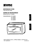
1
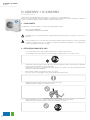
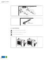
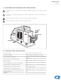
DC Inverter R410A
Sistemi per la climatizzazione
M A NUA LE D’ US O
FreeDom OUTDOOR D.32M3INV • D.34M4INV
D.32M3INV • D.34M4INV
FreeDom
D.32M3INV • D.34M4INV
DC Inverter R410A
Leggere questo manuale prima di procedere all’uso, e conservarlo con cura come riferimento.
In linea con la politica aziendale di continuo miglioramento dei prodotti, le caratteristiche estetiche, le dimensioni, i dati tecnici
e gli accessori di queste apparecchiature potrebbero cambiare senza preavviso.
1 - CONFORMITA’
Il condizionatore che avete acquistato è conforme alle seguenti direttive europee:
•
Basso voltaggio 2006/95/EC
•
Compatibilità elettromagnetica 89/336/EEC
Prima di procedere con qualsiasi operazione, leggere attentamente questo manuale e conservarlo con cura per consultazioni.
Usare il condizionatore solo
come
indicato in questo libretto
di istruzioni.
THE
INSTRUCTIONS
BEFORE
USEQueste istruzioni non coprono ogni possibile
condizione e situazione. Buon senso e cautela sono sempre raccomandati per l’installazione, uso e manutenzione,
come per ogni applicazione elettrica casalinga.
2 - ISTRUZIONI PRIMA DELL’USO
WARNING
When
having
a burning smell BEFORE USE
THE
INSTRUCTIONS
The power supply must adopt
.
1
In caso di odore di bruciato
o fumo, please
togliere turn
l’alimentazione
e contattarethe
il centro
servizi.
or smoke,
off the power
special
circuit that with air switch
Se l’anomalia persiste, l’unità potrebbe essere danneggiata e potrebbe causare corto circuiti o incendi.
supply and contact with the service
center .
protection and assure it has enough
capacity. The unit will be turned on or
WARNING
N
cables
cable a
damage
off according to your requirement
When having a burning smell
The power
supply
automatically, please
do not
turn must
on adopt
or smoke, please turn off the power
special
circuit that
with air switch
or turn offthe
the unit
frequently,
otherwise
protection
it has enough
supply and contact with the service
disadvantage
effect and
mayassure
be caused
2.
L’alimentazione deve prevedere
un
switch
di
protezione
per
isolare
l’impianto
elettrico
assicurandosi
che
abbia
abba-on or
capacity.
The
unit
will
be
turned
to the unit.
If the abnormity
exists, the unit
center del
.stillprodotto.
stanza capacitàBEFORE
per supportare
i consumi
THE INSTRUCTIONS
USE
GENERAL
INFORMATION
off
according
to
your
requirement
mayo be
damaged,
may cause
L’unità potrà essere accesa
spenta
in base and
alle vostre
richieste; non spegnere e accendere l’unità frequentemente,
automatically, please do not turn on
altrimenti essa subirà danneggiamenti.
electric shock or fire.
.
3
WARNING
or turn off the unit frequently, otherwise
Mai scollegare o tagliare i caviPower
elettricimust
di potenza
e di
controllo.
adopts
the
special
Disconnect
the power
if caused
★ Ne
disadvantage
effectsupply
may be
Nel caso in cui fossero danneggiati, sarà necessario farli riparare da professionisti.
circuit to Ifprevent
fire.
long putting
air conditioner out of
use th
to thethe
unit.
the abnormity
still exists, the unit
Never cut off or damage power
The power supply must adopt
may be damaged, and may causeuse.
appoin
or smoke, please turn off the power
cables and control wires. If the power
the special circuit that with air switch
electric shock or fire.
protection and assure it has enough
cable and signal control wire were
supply and contact with the service
capacity.
The
unit
will
be
turned
on
or
damaged,
change them
by professional
Power must adopts the special
Disconnect
the power
supply if
center .
4.
L’alimentazione deve prevedere off
circuiti
specifici per
incendi.
according
to prevenire
your requirement
circuit
to
prevent
fire.
long
putting
the
air
conditioner
out of
Altrimenti potrebbero verificarsi corto circuiti o incendi.
automatically, please do not turn on
use.
or turn off the unit frequently, otherwise
When having a burning smell
disadvantage effect may be caused
Otherwise, it can cause electric
Otherwise, the accumulated dusts
to the unit.
If the abnormity still exists, the unit
may
cause overheating or fire.
shock or fire.
may be damaged, and may cause
★ When cleaning, it is necessary
electric shock or fire.
Rated voltage of this airconditioner
2
Otherw
fire.
D
to stop driving and turn off the
by yo
220-240V~50Hz,The compressor
Power must adopts the special
Disconnect the power supply if
★ Never damage the electric wire or
power supply.
Otherwise, it can cause electric will vibrate
Otherwise,
sharply ifthe
theaccumulated
voltage is dusts
5.to prevent
Togliere
l’alimentazione nel caso long
in cui putting
il condizionatore
non venga utilizzato
lungothe
tempo.
circuit
fire.
the air conditioner
out of per use
electric wire which is not
too
low,
resulting
in
damage
to or fire.
may
cause
overheating
shock causare
or fire. surriscaldamento
Altrimenti l’accumulo di polvere potrebbe
o incendio.
Cut off power supply
use.
appointed.
refrigerating system. Electrical
★ When cleaning, it is necessary
Rated
of this ifairconditioner
component are
easyvoltage
to damage
to stop driving and turn off the
220-240V~50Hz,The compressor
the voltage is too high.
power supply.
will vibrate sharply if the voltage is
The w
too low, resulting in damage to
Cut off power supply
shock
refrigerating system. Electrical
Otherwise, it may cause electric
servic
shock or damage.
component are easy to damage if
Otherwise, it can cause electric
Otherwise, the accumulated dusts
Otherwise, it will cause overheating or
the voltage is too high.
maynote
cause
overheating
fire.
Don't
step on the top of the outdoor unit
shock or fire.
Please
whether
the installed or fire.
or place something on it.
stand is firm enough or not.
eart
disadvantage effect may be caused
to the unit.
WARNING
The power supply must adopt
electric
shock
or fire. with the service
supply
and contact
center
Power. must adopts the special
cut offfire.
or damage power
circuitNever
to prevent
THE
INSTRUCTIONS
cables and control wires. If the power
the
special
circuit that with BEFORE
air switch USE
protection
and the
assure
it has
enough
cable
and
signal the
control
wirewire
were
Disconnect
power
supply
if
Never
damage
electric
or
★
capacity. The unit will be turned on or
damaged,
change
them
by
professional
long putting
the
conditioner
outelettrici
of
use the
wireadatti.
which
is not
6.
Mai air
danneggiare
i cavi
o usare
elettrici
non
Ifcavi
theelectric
abnormity
still
exists,
the unit
off according
to your
requirement
Altrimenti
questo
causerebbe surriscaldamento o incendi.
may be damaged, and may cause
use.
appointed.
automatically, please do not turn on
electric
shock or
fire. must adopt
When having a burning smell
The power
supply
or turn off the unit frequently, otherwise
or smoke, please turn off the power
the special circuit that with air switch
disadvantage effect may be caused
Power must adopts the special
protection
and assure it has enough
and contact with the service
tosupply
the unit.
Otherwise,
can cause
circuit toitprevent
fire. electric
capacity. The unit will be turned on or
center .
shock or fire.
off according to your requirement
WARNING
protection and assure it has enough
cable and signal contro
capacity. The unit will be turned on or
damaged, change them by
D’USO
Disconnect the power supply if
Never damage
the elec
★MANUALE
off according to your requirement
FreeDom
long
putting the air
conditioner
automatically,
please
do notout
turnof on use the electric wire which
GENERAL INFORMATION
use.
or turn off the unit frequently, otherwise appointed.
disadvantage effect may be caused
to the unit.
Never cut off or damage power
cables and control wires. If the power
Disconnect the power supply if
cable and signal
control wire
were
Otherwise,
the the
accumulated
dusts
long putting
air conditioner
out of
damaged, change them by professional
may
cause
overheating
or
fire.
use.
★ Never damage the e
Otherwise,
will cause
use the itelectric
wireove
w
fire.appointed.
automatically,
please itdois necessary
not turn on
★ When cleaning,
Rated voltage of this airconditioner
Otherwise, the accumulated dusts
Otherwise, it will cause overheating or
powerlasupply
if
Never
damage
the
or
or
off
the
frequently,
to
stop
driving
and
turnelectric
offotherwise
thewire
★turn
7. Disconnect
Mentrethe
si effettua
pulizia dell’apparecchiatura,
èunit
necessario
togliere
l’alimentazione
al prodotto.
220-240V~50Hz,The
compressor
may cause
overheating
or fire.
fire.
Altrimenti
potrebbero
verificarsi
circuiti
oelectric
danni
similari.
disadvantage
effect
be is
caused
power
supply.
long putting
the air conditioner
out of corto
use
the
wiremay
which
not
will vibrate sharply if the voltage is
to
the unit.
If the abnormity still exists, the unit
too low, resulting in damage to
use.
appointed.
Don't attempt to repair theCutair
conditioner
Rated voltage of this airconditioner
off power
supply
may be damaged, and may cause
refrigerating system. Electrical
by yourself.
220-240V~50Hz,The compressor
electric shock or fire.
component
are
easy
to damagedusts
if
Otherwise,
it
can
cause
electric
Otherwise,
the
accumulated
will vibrate sharply if the voltage is
Don't attempt to repair the
by yourself.
too low,
resulting
in damage
to
Power
must adopts
the special
refrigerating
system.
Electrical
circuit to prevent fire.
fire.
The wrong repair will lead to a
Don't
to repairc
shock or
fire, attempt
so you should
by yourself.
service center to repair.
Disconnect
shock
or fire. the power supply if
the
voltage
is too
high.
cause
overheating
or wire
fire. or
Never
damage
the electric
★may
long putting the air conditioner out of
electric wire which is not
★ When cleaning, it is necessary use theRated
voltage of this airconditioner
use.
to220-240V
stop driving
and
turn off
thevibrerà inappointed.
8.
Il voltaggio di questo condizionatoreOtherwise,
è
il cause
compressore
caso
di voltaggio troppo basso,
it50Hz,
may
electric
220-240V~50Hz,The
compressor
the
voltage is
toorefrigerando
high.
non
l’ambiente
elettrici
si danneggiano
facilmente se il voltaggio è troppo
Otherwise,
the
accumulated
dusts correttamente.
Otherwise,
it will cause
overheating
or
power
supply.
shock
orI componenti
damage.
will vibrate sharply if the voltage is
elevato.
The wrong repair will lead to an electric
may cause overheating or fire.
fire.
too low, resulting in damage to
Cut off the
power supply
shockPlease
or fire,
so you
shouldthe
contact
Don't step on the top of the outdoor unit
whether
installed
9.
Non cercare di riparare il condizionatore
da
soli.note
refrigerating
system.
Electrical
RatedUn’errata
può causare service
un
corto
o un
incendio,
quindi
è necessario
contattare
il centro
per
Don't
attempt
to repair
the air
conditioner
or place
something
on servizi
it.
center
to
repair.
voltage ofriparazione
this airconditioner
stand
iscircuito
firm
enough
or not.
una corretta riparazione.
component
are
easy
to
damage if
by yourself.
220-240V~50Hz,The compressor
the voltage is too high.
will
vibrate
sharply
voltageunit
is
Don't
step on
the top ifofthe
the outdoor
Earthing:the
Theaccumulated
unit must be reliably
Otherwise,
it
can
cause
electric
Otherwise,
dusts
Otherwise,
it will cause overheating or
too low,
resulting
in damage to
or place
something
on it.
earthed. The earthing cable shall
may cause overheating or fire.
fire.
shock or fire. system. Electrical
refrigerating
Otherwise,
it special
may cause
be connected
to the
earthingelectric
component
are easy to
if
it isdamage
necessary
shock
orvoltage
damage.
★ When cleaning,
device
in the
construction.
Don't attempt to repair the air conditioner
Rated
of this airconditioner
thestop
voltage
is too
high.
to
driving
and
turn off the
by yourself.
220-240V~50Hz,The compressor
Don't step on the top of the outdoor unit
The wrong
repair
lead tothe
an installed
electric
Please
notewill
whether
power
supply.
will
vibrate
sharply
if
the
voltage
is
10.
Verificare che la base di appoggio sia stabile.
or
place
something on it.
stand
is
firm
enough
or
not.
shock
or
fire, soitlamay
you
should
Nel caso in cui fosse danneggiata, potrebbe
causare
caduta
dell’
unità the
causando lesioni
o altri
alle unit
persone.
As falling
off incidenti
the outdoor
can be
Iftoo
it is damaged,
lead
tocontact
the
low,
resulting
in damage
to
Cut off power supply
service
center
to
repair.
dangerous.
fall
of the unit andsystem.
cause the
injury.
refrigerating
Electrical
component are easy to damage if
Don't
the top
ofcan
the outdoor
unit
As falling
offstep
the on
outdoor
unit
be
or place something on it.
dangerous.
Otherwise, it may cause electric
shock or damage.
component are easy to damage if
Earthing:
must be reliably
the voltage
is The
too unit
high.
earthed. The earthing cable shall
2 be connected to the special earthing
device in the construction.
If it is damaged, it may lead to the
Otherwise, it will cause o
Earthing: The unit must b
earthed. The earthing cab
be connected to the special
device in the construction
The wrong repair will lead
shock or fire, so you shou
service center to repair.
Earthing: The unit mu
earthed. The earthing
be connected to the spe
device in the construc
The wrong repair will lead to an electric
shock or fire, so you should contact the
service center to repair.
As falling off the outdoor unit can be
Don't step on the top of the outdoor unit
PleaseNon
notesedersi
whether
the installed oggetti sull’unità
1.
1
o appoggiare
dangerous.
Earthing: The unit must be reliably
fall ofesterna.
the unit and cause the injury.
or
place
something
on it. causare lesioni o altri incidenti alle persone
is firm
La caduta
potrebbero
stand
enoughdell’unità
or not. o di oggetti posti su di questa
earthed. The earthing cable shall
be connected to the special earthing
device in the construction.
As falling off the outdoor unit can be
dangerous.
2
falling offtramite
the outdoor
can bead un affidabile dispositivo di messa a terra.
If it1is
lead
to the deve essereAs
2.damaged,
Messait may
a terra:
il prodotto
collegato
il cavo unit
specifico
dangerous.
fall of the unit and cause the injury.
2
3
D.32M3INV • D.34M4INV
FreeDom
3 - NOMI DELLE PARTI
ttenzione:
A
•
Assicurarsi di staccare l’alimentazione prima di pulire il condizionatore altrimenti potrebbero verificarsi corto circuiti.
•
Bagnare il condizionatore potrebbe causare il rischio di corto circuito. Non lavare il vostro condizionatore in alcun
•
Liquidi evaporanti come diluenti o benzina causano danni all’estetica dell’apparecchiatura. Usare solo panni morbidi
e asciutti per pulire la carcassa del condizionatore.
NAMES
NAMESOF
OFTHE
THEPARTS
PARTS
caso.
Warning
Warning
GENERAL
GENERALINFORMATION
INFORMATION
zzIfIfthe
thesupply
supplycord
cordisisdamaged,
damaged,ititmust
mustbe
bereplaced
replacedby
bythe
themanufacturer
manufacturer
•
Il prodotto non dovrà essere smaltito insieme ai rifiuti domestici.
ororits
itsservice
serviceagent
agentororaasimilarly
similarlyqualified
qualifiedperson
personininorder
ordertotoavoid
avoidaahazard.
hazard.
Il prodotto deve essere smaltito in un luogo autorizzato per il riciclaggio delle apparecchiature elettriche.
Be
sure
to
cut
off
the
power
supply
before
cleaning
the
air
conditioner;
zz Be sure to cut off the power supply before cleaning the air conditioner;
otherwise
happen.
otherwiseelectric
electricshock
shock
mightLa
happen.
• might
temperatura del circuito refrigerante può raggiungere temperature molto elevate, si prega ti tenere lontani i cavi di
cause
ofofelectric
shock.
Make
zzWetting
Wettingofofair
airconditioner
conditionermay
maycollegamenti
causethe
therisk
riskelettrici
electric
shock.
Make
dai
tubi di
rame.
sure
surenot
nottotowash
washyour
yourair
airconditioner
conditionerininany
anycase.
case.
Volatileliquids
liquidssuch
suchas
asthinner
thinnerororgasoline
gasolinewill
willcause
causedamage
damagetotothe
the
zz Volatile
appearance
appearanceofofair
airconditioner.
conditioner.(Only
(Onlyuse
usesoft
softdry
drycloth
clothmoist
moistcloth
clothclean
clean
the
theair
airconditioner
conditionercabinet).
cabinet).
as
municipal
zz Do
Donot
notdispose
disposethis
thisproduct
product
asunsorted
unsorted
municipalwaste.
waste.
UNITA’
ESTERNA
11
Collection
Collectionofofsuch
suchwaste
wasteseparately
separatelyfor
forspecial
specialtreatment
treatment
N.
Descrizione
isisnecessary.
necessary.
z
z
The
Thetemperature
temperatureofofrefrigerant
refrigerantcircuit
circuitwill
willbe
behigh,please
high,pleasekeep
keepthe
the
1 from
griglia d’aerazione
interconnection
the
interconnectioncable
cableaway
awayfrom
thecopper
coppertube.
tube.
2
valvola
OUTDOOR
OUTDOORUNIT
UNIT
22
No.
No. Description
Description
11 Air
Airoutlet
outletgrille
grille
22 Valve
Valve
11
22
Note:
Note:the
the above
above figures
figures are
are only
only intended
intended to
to be
be aa simple
simple
diagram
diagram ofof the
the appliance
appliance and
and may
may not
not correspond
correspond to
to the
the
appearance
appearanceofofthe
theunits
unitsthat
thathave
havebeen
beenpurchased.
purchased.
GENERAL
GENERALINFORMATION
INFORMATION
TECHNICAL
TECHNICALDATA
DATA
Nota: le figure sono solo un semplice raffigurazione e potrebbero non corrispondere alle unità che sono state acquistate.
Electrical
Electricaldata
data
Electricity
Electricitysupply
supply
220-240V
220-240V~50
~50
30
30
4.0
4.0
Fuse
Fuseororair
airswitch
switch
Minimum
Minimumpower
powercord
cordsection
section
Refrigerant
Refrigerantgas
gas
Size
Sizeand
andclearance
clearance
LL
R410
R410AA
WW
MOD
MOD
HH
Maximum
Maximumcooling
cooling
Minimum
Minimumcooling
cooling
4
Maximum
Maximumheating
heating
Minimum
Minimumheating
heating
))
mm
mm2 2
GWHD(24)NK3CO
GWHD(24)NK3CO
GWHD(28)NK3AO
GWHD(28)NK3AO
LL
950
950
mm
mm
W
W
420
420
mm
mm
HH
840
840
mm
mm
OUTDOOR
OUTDOORUNIT
UNITWORKING
WORKINGTEMPERATURE
TEMPERATURERANGE
RANGE
Outdoor
Outdoorside
sideDB/WB(
DB/WB(
43/26(T1)
43/26(T1)
21/21/24/18
24/18
-5/-6
-5/-6
VV~Hz
~Hz
AA
GENERAL
GENERALINFORMATION
INFORMATION
OUTDOOR UNIT
MANUALE D’USO
FreeDom
No. Description
4 - DATI TECNICI
1
Air outlet grille
2
Valve
2
1
Dati elettrici
Alimentazione
220-240~50
V~Hz
Fusibile
30
A
Sezione minima cavo d’alimentazione
4.0
mm²
Gas refrigerante
R410A
2
Misure
MOD
Note: the above figures are only intended to be a simple
diagram of the appliance and may not correspond to the
appearance of the units that have been purchased.
D32M3INV
L
P
H
D34M4INV
950
TECHNICAL
DATA
420 data
Electrical
Electricity supply
GENERAL INFORM
mm
mm
Fuse or840
air switch
Minimum power cord section
220-240V ~50
30
4.0
mm
Refrigerant gas
Size and clearance
L
R410 A
W
MOD
H
L
950
W
420
H
840
OUTDOOR UNIT WORKING TEMPERATURE RANGE
Outdoor side DB/WB(
43/26(T1)
21/24/18
-5/-6
5 - TEMPERATURE DI FUNZIONAMENTO DELL’UNITA’ ESTERNA
Maximum cooling
Minimum
cooling
Outdoor side
DB/WB (°C)
Massimo in raffreddamento
Maximum heating
43/26(T1)
Minimum heating
Minimo in raffreddamento
21/-
Massimo in riscaldamento
24/18
Minimo in riscaldamento
-5/-6
GWHD(24)NK3CO
GWHD(28)NK3AO
GENERAL INFORM
)
5
D.32M3INV • D.34M4INV
FreeDom
6 - COLLEGAMENTI ELETTRICI
D32M3INV
1.
Rimuovere il pannello che si trova sul lato destro dell’unità esterna.
ELECTRICAL
CONNECTIONS
INSTALLER
2.
Connettere i cavi sulla morsettiera come da figura assicurandosi che le linee di connessione corrispondano a quelle
riportate
GWHD(24)NK
3 C Osulle
: unità interne
3. handle
Fissare
il cavo
di alimentazione
1.Remove the
at the
right
side plate of the
An all-pole disconnection switch having a contact
outdoor unit (one screw).
4.
Assicurarsi che i cavi siano ben fissati.
separation of at least 3mm in all pole should be
the cable
clamp, connect the power connection
2. Remove 5.
Rimettere il pannello.
connected in fixed wiring.
cable with the terminal at the row of connection and fix
the connection. The fitting line distributing must be
Lasciare almeno 3mm di distanza tra i fili di collegamento
consistent
with the indoor unit. terminal of line bank.
Wiring should meet that of indoor unit.
Wrong wire connection may cause malfunction of some
electric components.After fixing cable, ensure that
leads between connection to fixed point have some spa
Una connessione errata dei cavi può causare il malfunzionamento di alcuni componenti elettrici. Dopo il fissaggio
Il prodotto deve essere elettricamente installato secondo le leggi
nazionali
vigenti.
national
wiring
regulations.
wire
byogni
wiresingolo
clamp.
3. Fix power connection
assicurarsi
che
filo non sia in contatto con altri The connection pipes and the connectiong wirings of
the unit A ,unit B and unit C must be corresponding to e
4. Ensure wire has been fixed well.
other respective.
handle.
Le tubazioni e le connessioni elettriche sull’unità esterna delle unità A e B, devono corrispondere con le unità stesse.
5. Install the
The appliance shall be installed in accordance with
Evitare di installare l’unità esterna in luoghi troppo esposti alla luce del sole.
Do not install the outdoor unit where it is exposed
to the sunlight.
Handle
To unit A
YEGN Blue
Blue
Brown Black
Power
cord
To unit B
YEGN Blue
Brown
interconnection
cable
Black
To unit C
YEGN
Brown
interconnection
cable
Blue
Black
YEGN
Brown
interconnection
cable
To the power supply
Outdoor unit
Indoor unit
6
MANUALE D’USO
FreeDom
D34M4INV
1.
Rimuovere la copertura frontale dell’unità esterna.
ELECTRICAL
CONNECTIONS
2.
INSTALLER
Connettere i cavi sulla morsettiera come da figura assicurandosi che le linee di connessione corrispondano a quelle
W H D ( 2 8 ) Nriportate
K 3 A sulle
O : unità interne
Remove3.the handle
side plate of the
Fissareatil the
cavoright
di alimentazione
outdoor unit (one screw).
An all-pole disconnection switch having a contact
separation of at least 3mm in all pole should be
4.
Assicurarsi che i cavi siano ben fissati.
Remove
the
cable
clamp, connect the power connection
.
5.
Rimettere la copertura frontale dell’unità esterna.
connected in fixed wiring.
cable with the terminal at the row of connection and fix
the connection. The fitting line distributing must be
Lasciare almeno 3 mm di distanza tra i fili di collegamento
consistent
with the indoor unit. terminal of line bank.
Wiring should meet that of indoor unit.
Wrong wire connection may cause malfunction of some
electric components.After fixing cable, ensure that
leads between connection to fixed point have some space.
Una connessione errata dei cavi può causare il malfunzionamento di alcuni componenti elettrici. Dopo il fissaggio
assicurarsiwire
che by
ogniwire
singolo
filo non sia in contatto con altri
Fix power connection
clamp.
The connection pipes and the connectiong wirings of
the unit A ,unit B,unit C and unit D must be corresponding to each
Ensure wire has been fixed well.
other
Le tubazioni e le connessioni elettriche sull’unità esterna delle unità A erespective.
B, devono corrispondere con le unità stesse.
Install the handle.
The
appliance
Il prodotto deve essere elettricamente installato secondo le leggi
nazionali
vigenti.shall be installed in accordance with
Evitare di installare l’unità esterna in luoghi troppo esposti alla luce del sole.
national wiring regulations.
Do not install the outdoor unit where it is exposed
to the sunlight.
Handle
To unit A
YEGN Blue
Blue
Brown Black
Power
cord
To unit B
YEGN Blue
Brown
interconnection
cable
Black
To unit D
To unit C
YEGN
Brown
interconnection
cable
YEGN
Blue
Black
Brown
interconnection
cable
YEGN
Blue
Black
Brown
interconnection
cable
To the power supply
Outdoor unit
Indoor unit
HANDLING
After having removed the packaging, check that the contents are intact and complete.
The outdoor unit must always be kept upright.
USER
Handling must be done by suitably equipped qualified
technical personnel using equipment that is suitable for
the weight of the appliance.
7
D.32M3INV • D.34M4INV
FreeDom
7 - PRIMA DELL’UTILIZZO
Dopo aver rimosso l’imballo, controllare che i contenuti siano intatti e completi.
L’unità esterna deve sempre essere mantenuta in posizione idonea anche nel trasporto.
L’unità deve essere maneggiata da personale tecnico qualificato che usi strumenti adatti al peso dell’applicazione.
8 - INSTALLAZIONE DELL’UNITA’ ESTERNA
8.1 - Posizione
Usare bulloni per fissare l’unità su un pavimento piatto e solido.
Quando si monta l’unità su una parete o sul soffitto, assicurarsi che il supporto sia fissato fermamente, in modo che
esso non si possa muovere in caso di intense vibrazioni o vento forte.
STALLING THE OUTDOOR UNIT
n
INSTALLER
Evitare di installare l’unità esterna in luoghi poco arieggiati quindi limitati.
e bolts to secure the unit to a flat,
floor.
8.2 -solid
Installazione
delle tubazioni
Do not install the outdoor unit where it is exposed
hen mounting the unit on a wall or the roof, make
to sunlight.
re the support is firmly secured so that it cannot
Usare
solo
tubazioni
adatte
per la connessione dei climatizzatori con refrigerante R410A.
ove in the event of intense vibrations or a strong
nd.
Le tubazioni refrigeranti non devono superare la massima lunghezza espressa nella tabella dati.
Rivestire tutte le tubazioni refrigeranti con i rispettivi giunti
o not install the outdoor unit in pits or air vents
ng the pipes
e suitable connecting pipes and equipment for the
Stringere le connessioni utilizzando chiavi dinamometriche appropiate.
rigerant R410A.
e refrigerant pipes must not exceed the maximum
ngths given in the technical data table.
8.3 - Installazione della pipetta di fuga per il condotto di drenaggio della condensa (per mo-
delli che dispongono della pompa di calore).
g all the refrigerant pipes and joints.
La condensa fuoriesce dall’unità esterna quando l’apparecchiatura sta operando nella modalità riscaldamento. Per non
ghten the connections using two wrenches
disturbareworking
i vicini e per rispettare l’ambiente, è necessario installare una pipetta di fuga per con il rispettivo condotto per incaopposite directions.
nalare la condensa come dimostrato nell’immagine.
the drain fitting and the drain hose (for
with heat pump only)
sation is produced and flows from the outdoor unit
e appliance is operating in the heating mode. In order
isturb neighbours and to respect the environment,
drain fitting and a drain hose to channel the condener. Install the drain fitting and rubber washer on the
unit chassis and connect a drain hose to it as shown
ure.
EEDING
air left inside the refrigerant circuit can cause commalfunction. After having connected the indoor
door units, bleed the air and humidity from the
ant circuit using a vacuum pump.
crew and remove the caps from the 2-way and 3valves.
crew and remove the cap from the service valve.
8
INSTALLER
MANUALE D’USO
FreeDom
9 - RILEVAMENTO PERDITE
L’aria umida che rimane nel circuito refrigerante può causare il malfunzionamento del prodotto.
Dopo aver connesso l’unità esterna ed interna, bisogna assolutamente espellere l’aria e l’umidità dal circuito refrigerante
usando una pompa per il vuoto.
.
1
2.
3.
4.
Svitare e rimuovere i bocchettoni esterni ai rubinetti
Svitare e rimuovere il bocchettone dalla valvola di servizio
Connettere il tubo della pompa alla valvola di servizio
Azionare la pompa fino al raggiungimento del vuoto all’interno dell’impianto (misurazione visibile sul vacuometro in
INSTALLER
TDOOR UNIT
dotazione sulla pompa). Maggiore è il tempo che la pompa rimane
in funzione migliore sarà l’espulsione di polveri,
umidità e aria presenti nell’impianto
5.
Una volta spenta la pompa del vuoto, verificare la tenuta dell’impianto tramite vacuometro, dopodiché chiudere la
it to a flat, solid
floor.di collegamento
manopola
isolando
vacuometro.
Install
the ildrain
fitting and the drain hose (for
a wall or the roof, make
model with heat pump only)
6. that Aprire
solo a questo punto i rubinetti in senso orario tramite una chiave a brugola verificando le tenute dei giunti tracured so
it cannot
Condensation
is produced
anduna
flows
outdoor unit
liquidi o dispositivi
elettronici specifici.
Si consiglia,
voltafrom
apertithe
completamente
i rubinetti di effettuare ½ giro
e vibrations ormite
a strong
when
the
appliance
is
operating
in
the
heating
mode.
In order
in senso anti-orario utile a salvaguardare le guarnizioni dei rubinetti stessi.
not to disturb neighbours and to respect the environment,
7.
Rimettere e avvitare install
i bocchettoni
rubinetti.
della pompa
vuoto
a draindeifitting
andDisconnettere
a drain hoseil tubo
to channel
the condenit in pits or air vents
sate water. Install the drain fitting and rubber washer on the
8.
Rimettere e avvitare il bocchettone della valvola di servizio
outdoor unit chassis and connect a drain hose to it as shown
in the figure.
and equipment for the
Diametro (mm)
Twisting moment (N·m)
6
15-20
9.52
35-40
ot exceed the maximum
16
es and joints.
60-65
12
g two wrenches
working 45-50
19
70-75
INSTALLER
circuit can cause comconnected the indoor
and humidity from the
ump.
from the 2-way and 3-
om the service valve.
to the service valve.
10-15 minutes until an
as been reached.
n operation, close the
m pump coupling. Stop
turn and then close it
e joints for leaks using
device.
d 3-way valves. Discon-
Vacuum pump
Vacuum pump
INDOOR
UNIT
on the valves.
Pompa a vuoto
Refrigerant fluid direction of flow
2-way valve
3-way valve
moment (N.m)
15-20
35-40
60-65
45-50
(6) Open by 1/4 turn
(7) Turn to open fully
Service
inlet
(2) Turn
(8) Secure
(7) Turn to open fully
Valve cap
(2) Turn
(2) Turn
Valve cap
(8) Secure
(8) Secure
Connect to the
indoor unit
9
Operate the vacuum pump for 10-15 minutes until an
nect the vacuum pump hose to the service valve.
bsolute vacuum of 10 mm Hg has been reached.
rate the vacuum pump for 10-15 minutes until an
With the vacuum pump still in operation, close the
D.32M3INV
D.34M4INV
ute vacuum
of 10• mm
Hg has been reached.
ow-pressure
knob on the vacuum pump coupling. Stop
h the FreeDom
vacuum pump still in operation, close the
he vacuum pump.
pressure knob on the vacuum pump coupling. Stop
Open the 2-way valve by 1/4 turn and then close it
acuum pump.
ter 10 seconds. Check all the joints for leaks using
n the 2-way valve by 1/4 turn and then close it
quid soap or an electronic leak device.
10 seconds. Check all the joints for leaks using
urn the body of the 2-way and 3-way valves. Discond soap or an electronic leak device.
ect the vacuum pump hose.
the body of the 2-way and 3-way valves. Disconeplace and tighten all the caps on the valves.
the vacuum pump hose.
ace and
tighten all the caps
on the
valves.
Twisting
moment
(N.m)
Diameter (mm)
��6
Diameter (mm)
��6 ��9.52
15-20(N.m)
Twisting moment
35-40
15-20
�� 16
��9.52
60-65
35-40
�� 16��12
45-50
60-65
��12��19
70-75
45-50
��19
70-75
Vacuum pump
Vacuum pump
Vacuum pump
Vacuum pump
INDOOR
UNIT
Pompa a vuoto
Refrigerant
fluid direction of flow
INDOOR
2-way valve
Pompa a vuoto
UNIT
3-way valve
Refrigerant fluid direction of flow
2-way valve
(6) Open by 1/4 turn
3-way valve
(7) Turn to open fully
Service
inlet
Service
inlet (2) Turn
(8) Secure
(2) Turn
(8) Secure
(7) Turn to open fully
Valve cap
Valve cap
(7) Turn to open fully
(6) Open by 1/4 turn
Valve cap
(7) Turn to open fully(2) Turn
Valve cap
(2) Turn
(2) Turn
(8) Secure
(8) Secure
(8) Secure
(2) Turn
Connect to the
(8) Secure
indoor unit
Connect to the
indoor unit
Le unità
e 18K unit
devono essere installate
l’ausilio
riduttore
12Kcon
and
18KdelMODE:
2K and 18K unit need to be installed
the12K
indoor
12 connection pipe with the "conversion joint"
12K and 18K MODE:
and 18K unit need to be installed the indoor unit
connection pipe with the "conversion joint"
conversion joint
conversion joint
10 - MANUTENZIONE
Usare strumenti adatti per il refrigeratore R410A
Non usare nessun altro refrigerante oltre al R410A
Non usare oli minerali per pulire l’unità
MAINTENANCE
INSTALLER
Use suitable instruments for the refrigerant R410A.
Do not use any other refrigerant than R410A.
Do not use mineral oils to clean the unit.
NSTALLATION DIMENSION DIAGRAM
The installation must be done by trained and qualified service personnel
with reliability according to this manual.
Contact service center before installation to avoid the malfunction due to
unprofessional installation.
When picking up and moving the units, you must be guided by trained and
qualified person.
Ensure that the recommended space is left around
the appliance.
10
INSTALLER
Do not use any other refrigerant than R410A.
MANUALE D’USO
FreeDom
Do not use mineral oils to clean the unit.
11 - DIAGRAMMA DELLE DIMENSIONI PER L’INSTALLAZIONE
INSTALLATION DIMENSION DIAGRAM
INSTALLER
The
L’installazione
deve
da personale
qualificato
ed affidabile
seguendo le istruzioni riportate su questo
installation
must
beessere
done eseguita
by trained
and qualified
service
personnel
manuale. according to this manual.
with reliability
Contact service center before installation to avoid the malfunction due to
unprofessional
Contattareinstallation.
il centro servizi prima dell’installazione per evitare il malfunzionamento causato da un’installazione non
professionale.
When picking up and moving the units, you must be guided by trained and
qualified person.
Durante la movimentazione dell’unità, è necessario essere aiutati da personale qualificato.
Ensure that the recommended space is left around
the appliance.
Assicurarsi che rimanga lo spazio necessario intorno all’apparecchiatura.
12 - CONTROLLI DOPO L’INSTALLAZIONE
Controllo dei prodotti.
Problemi inerenti ad un’installazione scorretta
È l’installazione affidabile?
L’unità potrebbe gocciolare, vibrare o fare rumore
È stato controllata la carica del gas?
È sufficiente l’isolamento termico delle unità?
È fluido il drenaggio?
La tensione d’alimentazione coincide con i dati di targa?
Sono state installate correttamente le tubazioni?
È stata fissata in modo sicuro la messa a terra?
I modelli delle linee sono conformi alle richieste?
Ci sono ostacoli vicino all’entrata e all’uscita dell’aria delle
unità esterne e interne?
La lunghezza delle tubazioni sono idonee alla carica di gas
refrigerante?
Potrebbe causare spiacevoli effetti di riscaldamento/raffreddamento
Potrebbe causare condensazione e gocciolamento di acqua
Potrebbe causare condensazione e gocciolamento di ac- 7
qua
L’unità potrebbe rompersi o i componenti potrebbero bruciarsi
L’unità potrebbe rompersi o i componenti potrebbero bruciarsi.
Rischio di scariche elettriche
L’unità potrebbe rompersi o i componenti potrebbero bruciarsi.
L’unità potrebbe rompersi o i componenti potrebbero bruciarsi.
Non è facile decidere la quantità di carica del refrigerante.
11
D.32M3INV • D.34M4INV
FreeDom
13 - POSSIBILI ACCOPPIAMENTI
D32M3INV
2 models
3 models
4 models
7K+7K
9K+9K
7K+7K+7K
7K+9K+9K
9K+9K+9K
7K+9K
9K+12K
7K+7K+9K
7K+9K+12K
9K+9K+12K
7K+12K
12K+12K
7K+7K+12K
7K+12K+12K
9K+12K+12K
7K+18K
9K+18K
7K+7K+18K
7K+9K+18K
9K+9K+18K
7K+12K+18K
9K+12K+18K
12K+12K+18K
12K+18K
NONE
D34M4INV
2 models
3 models
4 models
7K+7K
9K+9K
7K+7K+7K
7K+9K+9K
9K+9K+9K
7K+7K+7K+7K
7K+7K+9K+9K
7K+7K+12K+12K
7K+9K
9K+12K
7K+7K+9K
7K+9K+12K
9K+9K+12K
7K+7K+7K+9K
7K+7K+9K+12K
7K+9K+9K+9K
7K+12K
12K+12K
7K+7K+12K
7K+12K+12K 9K+12K+12K 7K+7K+7K+12K
7K+9K+12K+12K 9K+9K+9K+9K
7K+18K
9K+18K
7K+7K+18K
7K+9K+18K
7K+9K+9K+12K
9K+9K+9K+12K
9K+9K+9K+18K
7K+12K+18K 9K+12K+18K 12K+12K+18K 7K+7K+7K+18K
7K+9K+9K+18K
9K+9K+12K+18K
12K+18K
9K+9K+18K
7K+7K+9K+18K
7K+9K+12K+18K 9K+12K+12K+18K
7K+7K+12K+18K 7K+12K+12K+18K
ote:
N
1.
2.
3.
12
Quando si installano le unità interne da 12K e 18K c’è la necessità di connettere il riduttore direttamente sul rubinetto
dell’unità esterna.
Quando la capacità totale delle unità interne supera la capacità totale dell’unità esterna non si garantisce la reale
capacità di funzionamento di ogni singola unità interna.
Per il corretto funzionamento si consiglia di non installare una sola un’unità interna.
MANUALE D’USO
FreeDom
14 - CARATTERISTICHE TECNICHE
Codice
D.32M3INV
D.34M4INV
Caratteristiche Tecniche
Refrigerante
gas
R410A
Classe di efficienza energetica estiva
EER > 3,25
A
Classe di efficienza energetica invernale
COP > 3,60
A
Tensione di alimentazione 50 Hz
V
220-240 V
Range di temperatura ambiente per il funzionamento
°C
-7 + 43
Capacità di raffreddamento max
W
10000
Capacità di raffreddamento medio
W
7100
Capacità di raffreddamento min
W
2700
Potenza assorbita nominale/min/max
W
2200(840-3110)
Capacità di riscaldamento max
W
11000
Capacità di riscaldamento medio
W
8500
Capacità di riscaldamento min
W
2800
Potenza assorbita nominale/min/max
W
2400(770-4000)
Rumorosità Unità Interna
dB (A)
Rumorosità Unità Esterna
dB (A)
52/55
Sbrinamento automatico
SI
Diametro tubi lato liquido
”
1/4
Diametro tubi lato gas
”
3/8 1/2
U.E. precaricata fino a lunghezza tubi
m
25
Lunghezza tubi massima
70
Dislivello max tubi
m
10
Ricarica aggiuntiva
g/m
22
Dimensioni Unità Interna LxHxP
mm
Peso Unità Interna
kg
Dimensioni Unità Esterna LxHxP
mm
950x840x420
Peso Unità Esterna
kg
75
Conformità alle norme
CE
R410A
A
A
220-240 V
-7 + 43
10000
8000
2700
2450(835-3090)
11000
9300
2800
2400(770-4000)
53/56
SI
1/4
3/8 1/2
30
70
10
22
950x840x420
75
CE
13
D.32M3INV • D.34M4INV
FreeDom
15 - GARANZIA
Gentile Cliente,
La ringraziamo per aver acquistato un prodotto Diloc certi che ne rimarrà soddisfatto. Qualora il prodotto necessiti di interventi
in garanzia, La invitiamo a rivolgersi al rivenditore presso il quale ha effettuato l’acquisto oppure ad uno dei nostri centri di
assistenza autorizzati dislocati nella CEE e riportati sugli elenchi telefonici e sui cataloghi dei nostri prodotti. Prima di rivolgersi
al rivenditore o alla rete di assistenza autorizzata, Le consigliamo di leggere attentamente il manuale d’uso e manutenzione.
Garanzia.
Con la presente, Diloc garantisce il prodotto da eventuali difetti di materiali o di fabbricazione per la durata di 24 mesi e copre
le sole parti di ricambio e la manodopera compreso il diritto di chiamata del tecnico dei primi 12 mesi.
Qualora durante il periodo di garanzia si riscontrassero difetti di materiali o di fabbricazione, le consociate Diloc, i Centri di
assistenza Autorizzati o i Rivenditori autorizzati situati nella CEE, provvederanno a riparare o (a discrezione della Diloc) a sostituire il prodotto o i suoi componenti difettosi, nei termini ed alle condizioni sotto indicate, senza alcun addebito per i costi di
manodopera o delle parti di ricambio. Diloc si riserva il diritto (a sua unica discrezione) di sostituire i componenti dei prodotti
difettosi o prodotti a basso costo con parti assemblate o prodotti nuovi o revisionati.
ATTENZIONE
L’intervento sarà effettuato solo in luoghi di facile e sicuro accesso, in caso contrario verranno addebitati i costi relativi. Leggere attentamente i casi di decadenza garanzia sotto riportati.
ondizioni.
C
1.
Questa garanzia avrà valore solo se il prodotto difettoso verrà presentato unitamente alla fattura di vendita o di un’attestazione del rivenditore (riportante la data di acquisto, il tipo di prodotto e il nominativo del rivenditore) accompagnata dallo scontrino fiscale.
Diloc si riserva il diritto di rifiutare gli interventi in garanzia in assenza dei suddetti documenti o nel caso in cui le informazioni ivi contenute siano incomplete o illeggibili.
2.
La presente garanzia non copre i costi e/o gli eventuali danni e/o difetti conseguenti a modifiche o adattamenti apportati al prodotto, senza previa autorizzazione scritta rilasciata da Diloc, al fine di conformarlo a norme tecniche o di
sicurezza nazionali o locali in vigore in Paesi diversi da quelli per i quali il prodotto era stato originariamente progettato
e fabbricato.
3.
La presente garanzia decadrà qualora l’indicazione del modello o del numero di matricola riportata sul prodotto siano
stati modificati, cancellati, asportati o comunque resi illeggibili.
.
4
Sono esclusi dalla garanzia:
a. Gli interventi di manutenzione periodica e la riparazione o sostituzione di parti soggette a normale usura e logorio;
b. Qualsiasi adattamento o modifica apportati al prodotto, senza previa autorizzazione scritta da parte di Diloc per potenziare le prestazioni rispetto a quelle descritte nel manuale d’uso e manutenzione;
c. Tutti i costi dell’uscita del personale tecnico e dell’eventuale trasporto dal domicilio del Cliente al laboratorio del Centro di Assistenza e viceversa, nonché tutti i relativi rischi;
d. Danni conseguenti a:
- Uso improprio, compreso ma non limitato a: (a) l’impiego del prodotto per fini diversi da quelli previsti oppure l’inosservanza delle istruzioni Diloc sull’uso e manutenzione corretti del prodotto, (b) installazione o utilizzo del prodotto non conformi alle norme tecniche o di sicurezza vigenti nel Paese nel quale viene utilizzato;
- Interventi di riparazione da parte di personale non autorizzato o da parte del Cliente stesso;
- Eventi fortuiti, fulmini, allagamenti, incendi, errata ventilazione o altre cause non imputabili alla Diloc;
- Difetti degli impianti o delle apparecchiature ai quali il prodotto fosse stato collegato.
5.
Questa garanzia non pregiudica i diritti dell’acquirente stabiliti dalle vigenti leggi nazionali applicabili, né i diritti del
Cliente nei confronti del rivenditore derivanti dal contratto di compravendita.
14
MANUALE D’USO
FreeDom
INDICE
1 - CONFORMITA’
2
2 - ISTRUZIONI PRIMA DELL’USO
3 - NOMI DELLE PARTI
2
4 - DATI TECNICI
5
5 - TEMPERATURE DI FUNZIONAMENTO DELL’UNITA’ ESTERNA
5
6 - COLLEGAMENTI ELETTRICI
6
7 - PRIMA DELL’UTILIZZO
8
4
8 - INSTALLAZIONE DELL’UNITA’ ESTERNA
8
8
8
8
8
8.1 - Posizione
8.2 - Installazione delle tubazioni
8.3 - Installazione della pipetta di fuga per il condotto di drenaggio della condensa (per modelli che dispongono della pompa di calore).
9 - RILEVAMENTO PERDITE
9
10 - MANUTENZIONE
10
11 - DIAGRAMMA DELLE DIMENSIONI PER L’INSTALLAZIONE
11
12 - CONTROLLI DOPO L’INSTALLAZIONE
11
13 - POSSIBILI ACCOPPIAMENTI
12
14 - CARATTERISTICHE TECNICHE
13
15 - GARANZIA
14
15
Naicon srl Via il Caravaggio, 25 Trecella
I-20060 Pozzuolo Martesana - Milano (Italy)
Tel. +39 02 95.003.1 Fax +39 02 95.003.313
www.naicon.com e-mail: [email protected]