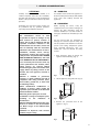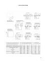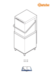
1
DISHWASHER INSTALLATION, OPERATION AND MAINTENANCE Page LAVASTOVIGLIE INSTALLAZIONE, USO E MANUTENZIONE Pagina 21 GESCHIRRSPÜLER INSTALLATION, BEDIENUNG UND WARTUNG Seite 41 LAVE-VAISSELLE INSTALLATION, EMPLOI ET ENTRETIEN Page 63 1 INDEX 1 - GENERAL RECCOMMENDATIONS .………………...……………………... Pag. 2 1A - HANDLING ……………………………………………………………...…... Pag. 2 1B - UNPACKING …………….………………………………….……………….. Pag. 2 1C - DISPOSAL …………………………………….……………………………... Pag. 3 1D – TECHNICAL DATA …………………………………..…………………….... Pag. 3 2 - INSTALLER AND MAINTENANCE PERSON INSTRUCTIONS ……...…...... Pag. 5 2A - WATER CONNECTION ……………………….………………………............. Pag. 5 2B - ELECTRICAL CONNECTION …………….………………………….……...… Pag. 6 2C - WARNING MESSAGES DISPLAYED ON THE CONTROL PANEL …………..… Pag. 6 2D - DETERGENT AND RINSE AID DISPENSERS AND SETTINGS …….……............ Pag. 8 2E - MANTEINANCE ………………………………………....………………......... Pag. 9 2F - UNINSTALL (long period of inactivity)……….............…….……………….... Pag. 9 3 - USER INSTRUCTIONS ……………..…..………………………………..... Pag. 10 3A - GENERAL RECCOMENDATIONS AND WARRANTY ……….………............... Pag. 10 3B - STARTING / WASH CYCLES (ELECTRONIC version) …………………............... Pag. 11 3C - STARTING / WASH CYCLES (MECHANICAL version)……............................…..... Pag. 14 3D - DAILY CLEANNING / END OF WORK ……….....................………………....... Pag. 17 3E - UNDERCOUNTER DISHWASHER WITH BUILT-IN WATER SOFTENER …....... Pag. 18 3F - WARNING MESSAGES DISPLAYED ON THE CONTROL PANEL …………..... Pag. 19 4 - TROUBLESHOOTING …………………....……………………….……..... Pag. 20 1 1 - GENERAL RECOMMENDATIONS ATTENTION Carefully read this instructions booklet, as it contains important advice for safe installation, operation and maintenance. Keep this booklet to hand in a safe place for future reference by other operators. 1A – HANDLING Use suitable means to move the appliance: a lift truck or fork pallet trucks (the forks should reach more than halfway beneath the appliance). 1B – UNPACKING Installation, use and service of the machine can be performed only by qualified personnel, especially trained to follow instructions: WARNING! The manufacturer cannot be held responsible for injuries or damages of any kind occurred to persons, machine or others, due to lack of conformity with the operation instructions indicated in this documentation and for abuse, misuse and lack of conformity with the instructions indicated in this documentation as well as installation, uninstall, service, tune-up, maintenance requiring the removal of the safety barriers not performed BY TRAINED AND AUTHORISED SPECIALISTS, will result in the IMMEDIATE LOSS OF THE WARRANTY. Loss of warranty will result also from any service performed to the machine, when: Safety barriers are removed without disconnecting the power line and the water supply. When any safety provision of the machine has been bypassed, removed or excluded. Machine is installed in provisional, improper or unsafe conditions for lack of compliance with safety provisions (fuses, main breaker, ground line, or water inlet and discharge valves). When unauthorized modifications or additions of devices which modify the operation cycles indicated on the data chart delivered with the machine. When not genuine spare parts are used. Installation or storage in inadequate spaces according to the indications of manufacturer. Machine utilization different from the scope foreseen as written in the documentation (ex. Dishes of type or sizes different from specified). Utilization of dispensers with corrosive products, not pure or dry. Before opening the boxes, verify the conditions and in case indicates damages on delivery slip. After unpacking, check the machine conditions, in case the machine is damaged, communicate immediately to the dealer. Do not proceed with the installation if damages are relevant to operate safely and wait for qualified and authorized assistance person. Save boxing components (plastic bags, expanded polystyrene, nails, etc.) outside the reach of children for safety reasons. 1- Wear protective gloves to unpack the appliance from the boxing. (Fig. 1) Fig.1 2- Lift the appliance using a lift truck. (Fig. 2) Fig.2 3- Remove the protection film of the appliance. (Fig. 3) Fig.3 2 ELECTRICAL CONNECTION 1C – DISPOSAL This appliance is marked according to the European directive 2002/96/EC on Waste Electrical and Electronic Equipment (WEEE). By ensuring this product is disposed of correctly, you will help prevent potential negative consequences for the environment and human health, which could otherwise be caused by inappropriate waste handling of this product. The symbol: on the product, or on the documents accompanying the product, indicates that this appliance may not be treated as household waste. Instead it shall be handed over to the applicable collection point for the recycling of electrical and electronic equipment. Disposal must be carried out in accordance with local environmental regulations for waste disposal. For more detailed information about treatment, recovery and recycling of this product, please contact your local city office, your household waste disposal service or the shop where you purchased the product. Voltage Frequency V Hz ±6% ±1% Wash Cycle Rinse Cycle °C °C 55 85 INSTALLATION ENVIRONMENT Operating Temperature °C °F 5 - 35 41 - 95 Storage Temperature °C °F 10 - 70 50 - 158 1D1– NOISE LEVEL Environment noise level cannot exceed the values as per Standards of place of installation. The noise of the machine, measured at the manufacturer site, has been less than 70dB, approximately 58dB. When using the machine following data must be complied with the storage, transportation, utilization and maintenance of the machine. Values of this documentation can be updated according to the state-ofthe-art and manufacturer can reserve the rights to modify present values. 1D – TECHNICAL DATA WATER CONNECTION Temperature Pressure Flow Hardness Mineral residues Conductivity °C °F kPA Bar PSI Lt/min °f °dH °e ppm mg/l µS/cm 50 122 200 - 500 2-5 29 - 72 20 - 30 7 - 14 4 - 7,5 5 - 9,5 70 - 140 300 / 400 300 / 400 3 INSTALLATION DIAGRAM 4 2 - INSTALLER AND MAINTENANCE PERSON INSTRUCTIONS ATTENTION 2A - WATER CONNECTION Specialists that install the machine are foreseen to train the operators about machine utilization and safety procedures to be followed. They must provide a real “demonstration” and verify that machine instructions are available to the operators. Following attentions should be taken: N.B. Shut-off valve, single direction, spool, sphere, lid control type, which can shut water supply off quickly and totally, selected to assure water pressure and flow as requested in the data diagram supplied with each machine. WARNING! 1- Position the dishwasher and level the appliance by turning the relative heightadjustable feet. (Fig.5) DO NOT OPEN THE DOOR QUICKLY IF CYCLE IS NOT ENDED. DO NOT DIP BARE HANDS IN WASHING SOLUTION. Fig. 5 DO NOT TAKE OFF THE MACHINE PANELS IF THE MACHINE HAS NOT BEEN DISCONNECTED FROM THE POWER AND WATER SUPPLY. DO NOT BYPASS THE MACHINE PROTECTIONS (MICROSWITCHES, PANELS, OR OTHERS) PROVIDED BY THE MACHINE MANUFACTURER IF NOT AT THE PRESENCE OF TRAINED SPECIALISTS THAT CAN TAKE PROPRER CAUTIONS. DO NOT UTILISE THE MACHINE TO WASH GOODS OUTSIDE THE SCOPE FOR WHICH IS PROVIDED FOR, OBJECTS OF SHAPE, TYPE, SIZE, AND MATERIAL NOT COMPATIBLE. DO NOT OPERATE THE MACHINE IF NOT PROPERLY CONNECTED, ACCORDING TO THE SPECIFICATIONS AND REQUIREMENTS OF THE LOCAL LAW AND PRESCRIPTION OF MANUFACTURER, MAKING SURE THAT ALL SAFETY DEVICES ARE OPERATIVE. ID/RATING/DATA PLATE ID/Rating plate of the appliance contains identification and technical data and is located on the front inside panel. - Extract the front panel with Allen tool or similar by inserting it inside the holes on the inferior part of the panel. Pull up the panel carefully. For Hoodtype models, unscrew the two screws located on the bottom of the panel. (Fig.4) 2- Connect the solenoid valve, which feed the machine, to water shut valve, using a flexible line. (Fig.6) Each machine must have its own water line supply. Fig. 6 2A1 – WATER SUPPLY PRESSURE Check that dynamic water supply pressure, measured between the appliance and the main, is between 200 and 500kPa. If the pressure is too high, fit a suitable pressure reducer on the inlet pipe. If the pressure is low, install an additional external pressure motor pump. (par.1D – Technical Data) - In case of new or long term appliance inactivity, drain the water line to eliminate air bubbles and foreign bodies present in new or unused water lines, which can damage the machine. 2A2 – WATER HARDNESS If water hardness is higher than acceptable, install a water softener if in the machine is not provided with an internal one, of adequate size prior the feed solenoid valve. (par.1D – Technical Data) If there is a high concentration of mineral residues in the water or high conductivity, we recommend installing the demineralization filter for 5/7° f. Fig.4 5 2A3 – MODELS WITH FREE FALL DRAINAGE N.B. The drainage line consists of a sump pit, free flow, of proper size capable to dispose twice the water flow indicated on the data diagram. It must be close to the drain pipe of the machine without bending, stretching, jointing the pipe. - Drain line must reach sump pit with free flow without constraints, stretching, bends, kinks, or being forced. - Connect the waste outlet pipe to the main drain pipe, fitting a trap, or place the outlet pipe over an “S” trap set into the floor. 2A4 – MODELS WITH DRAIN PUMP - Position the outlet pipe at a height anywhere between 750 and 1000mm from the floor. (Fig.7) WARNING! THE MANUFACTURER IS NOT RESPONSIBLE FOR DAMAGES OR INJURIES CAUSED FOR IMPROPER GROUNDING. THE GROUND AND THE ELECTRICAL CONNECTIONS SHOULD BE IN COMPLIANCE WITH NATIONAL REGULATIONS. The line cable can be replaced only with a spare cable supplied by the manufacturer. For replacement indicate machine type, machine serial number and possible modifications of the installation. Power cable cannot be stretched kinked, pressed, during normal operation, service or anytime. Earth equilibrating point on machine must be connected to nearest appliance terminal according to Safety Standards using a 2.5 – 10 mm. 2C - WARNING MESSAGES DISPLAYED ON THE CONTROL PANEL (Electronic version only) Fig. 7 2B - ELECTRICAL CONNECTION N.B. All contacts must be mechanically open, ground line included, min. distance between contacts 3 mm, with magnetic overload or fuses, calibrated for a max, sustained current agree with machine plat. It must be installed outside the machine but close to it. It must feed one machine only at time. Machine cannot be connected to mains using adapters, plug, cables or cable extensions not properly sized and adequate to the machine power requirements. - Verify main specifications must comply with indicated requirements on the data plate located inside of the front bottom panel of the machine (par. ID/RATING/DATA PLATE), that exists for the connection, a main breaker with proper size suitable for the machine and a proper ground system. N.B. If the machine is in OFF mode, warning messages are not displayed. Turn ON the machine to visualize the type of warning message on the appliance. Following warning messages on the display are provided: ntcb E-01 BOOSTER TEMPERATURE PROBE Booster temperature probe not connected or faulty. Verify that the probe is correctly and well connected to the electronic board. Verify that the probe is correctly positioned inside the booster and there is not presence of limestone on it. ntcu E-02 TANK TEMPERATURE PROBE Tank temperature probe not connected or faulty. 6 Verify that the probe is correctly and well connected to the electronic board. Verify that the probe is correctly positioned inside the tank and there is not presence of limestone on it. FILL E-03 Verify that the overflow device is completely removed and not obstructions are present on the water drain line. Verify that drain wires is correctly connected to the electronic board. bnot E-07 WATER FILL BOOSTER HEATING Water fill not completed during the available maximum time (10min). Maximum booster heating time reached (15min). Verify that water supply is correctly connected, opened and free of obstructions. Verify that solenoid valve filter is free of possible obstructions and deposit. Verify that water supply pressure is adequate (par.1D – Technical Data). Verify that machine’s door is completely closed and the overflow device is correctly positioned inside the tank. Verify that heater element wires are correctly connected to the electronic board. Verify that heater element works correctly and there is not presence of limestone on it. N.B. If water fill timing expires or in case of water level signal is not respected solenoid valve is automatically interrupted. To restart solenoid valve press any button on the control panel. T bo E-04 BOOSTER TEMPERATURE LIMIT Booster temperature maximum reached (set point +14°C / 57°F). set TANK TEMPERATURE LIMIT Tank temperature maximum set point reached (set point +7°C / 44°F). SUBSTITUE THE ELECTRONIC BOARD drA E-06 Maximum (30min). TANK HEATING tank heating time reached Verify that heater element wires are correctly connected to the electronic board. Verify that heater element works correctly and there is not presence of limestone on it. SEruICE E-09 PARAMETERS ERROR OR DAMAGED BOARD point SUBSTITUE THE ELECTRONIC BOARD T UA E-05 unot E-08 DRAIN ANOMALY Drainage not completed on the maximum programmed timing. Memory parameters error or damaged board. SUBSTITUE THE ELECTRONIC BOARD ACTIONS FOLLOWED TO THE WARNINGS: Booster and tank heating elements are interrupted, all loads are disactivated, the electronic board displays warning codes and it is inactivated. All control panel leds are Off. Cycle is interrupted “hold mode” until the breakdown is reseted. It is always possible to turn Off and On the appliance trought the button. SAFETY THERMOSTAT All machines are provided with a safety heatswitch that shuts machine off in case of overheating (120°C/248°F). To reset the thermonstat device press the push-button behind the control panel of the thermostat. 7 2D - DETERGENT AND RINSE AID DISPENSERS AND SETTINGS Before starting a new cycle the dispenser and its pipe must be completely filled. Check the level of the detergent or rinse aid and eventually fill-up the tank. N.B. The level in the detergent or rinse aid tank must not get empty or filled with corrosive or inadequate products. The warranty does not cover damages caused by improper use of dispenser. The dispenser is calibrated at manufacturer site: dispenser settings after installation can be performed only by qualified specialists. 1- Extract the front panel with Allen tool or similar by inserting it inside the holes on the inferior part of the panel. Pull up the panel carefully. For Hoodtype models, unscrew the two screws located on the bottom of the panel. (Fig.8) Fig.8 Quantity for the first setting should be according to the installator after evaluating the hardness of the water and the type of rinse aid used. Recommended vacum standard quantity of rinse aid from the included tube 4 x 6 correspond to approximately 4 cm = 0,5cc = 0,5 gr. for each 50 x 50 standard rack machine. Otherwise, approximately 2,5 cm = 0,3 = 0,3 gr. for 35 x 35 and 40 x40 standard rack glasswasher. Maximum dosing permit is approximately 25,8 cm = 3,6 cc = 3,6 gr. After first setting rinse aid dosage must be optimize by evaluating washing results after few cycles. 2D2 – PERISTALTIC RINSE AID AND DETERGENT DISPENSER Setting of rinse aid dispenser is perfomed acting on the screw accessible after removal of front panel, under the tank door. (see Fig.8) 1- Close gently all the way down the dispenser by screwing anticlockwise the needle valve of the dispenser. 2- Open up until reached necessary quantity by screwing clockwise the needle valve of the dispenser. (Fig.11) Before removing the front panel make sure the machine is disconnected from the main breaker. 2- Insert included dispenser tube inside the detergent or rinse aid tank. (if available). (Fig.9) Fig.11 Fig.9 2D1 – PRESSURE RINSE AID DISPENSER Setting of rinse aid dispenser is perfomed acting on the screw accessible after removal of front panel, under the tank door. (see Fig.8) 1- Close gently all the way down the dispenser by screwing anticlockwise the needle valve of the dispenser. 2- Open up until reached necessary quantity by screwing clockwise the needle valve of the dispenser. (Fig.10) Quantity for the first setting should be according to the installator after evaluating the hardness of the water and the type of rinse aid used. Recommended rinse aid standard quantity is 0,16 gr/sec that correspond to the maximum flow rate of the dispenser. Recommended detergent standard quantity is 0,77 gr/sec that correspond to the maximum flow rate of the dispenser. SUGGESTION To check the effectivness of the rinse aid, look at freshly washed glasses against the light. Drops of water remaining on the glass indicate an insufficient amount while streaks indicate an excess. (next page) Fig.10 8 In case of light coated presence that block dispenser functions, remove the coat by soaking the dishes for 30 minutes in a solution water soap (1:10) before starting machine cycle. 2D3 – DISHWASHERS WITHOUT DETERGENT DISPENSER Manually add recommended detergent quantity from the supplier every 5 cycles. Doses differ depending on water hardness and soiled quantity that remain on the dishes. N.B. All dishwashers are ready to be installed external dispenser or specific dispenser kit through injector and relative tube or through the hole with relative cap located on the tank of the machine. If changing to a different detergent or rinse aid type (even one by the same manufacturer), you must rinse the suction and pressure hoses with fresh water before connecting the new detergent or rinse aid container. Otherwise, the mixing of different types of detergent or rinse aid will cause cristallisation, which may result in a breakdown of the dosing pump. Failure to observe this condition will invalidate the guarantee and product liability. WARNING! DETERGENT SELECTION AND DOSAGE ARE FUNDAMENTAL FOR WASHING GOOD RESULTS AND TO MANTAIN MACHINE PERFORMANCES FOR LONG TIME AND EXTENDED LIFE. FOLLOW ALWAYS THE INSTRUCTIONS OF THE MANUFACTURER OF CLEANNING AGENTS. IMPROPER DOSAGES RESULT IN UNSATISFACTORY WASHING RESULTS AND REPRESENT SOURCES OF RIVERS AND SEAS POLLUTION. DO NOT USE CORROSIVE OR POLLUTANT PRODUCTS TO PROTECT AND MAINTAIN MACHINE, NEVER EXCEED DOSAGES INDICATED BY DETERGENT MANUFACTURER. NEVER LEAVE THE DISPENSER DRY OR CHARGED WITH CORROSIVE OR FOREIGN PRODUCTS WHICH WILL RESULT IN LOSS OF WARRANTY. 2E - MAINTENANCE 1- Descale the boiler, the internal surface of the tank and the appliance water piping once or twice a year. 2- Descale the rinse and wash jets every month using vinegar or a descaling agent. 3- The internal hose of the rinse aid and detergent peristaltic dispenser should undergo periodic maintenance (once or twice a year). 4- Clean solenoid valve filter by extracting it from the inside of the valve and by unplugging the water inlet tube. 2F - UNINSTALL (Long period of inactivity) Machine can be taken out of operation only by trained specialists authorized for the purposes, who will provide for: 1- Shut water line off (water valve) and electric supply (main breaker). 2- Completely drain the tank. 3- Remove and carefully clean the filters. 4- Completely drain the incorporated dispenser hoses, removing them from the containers. 5- Drain the detergent and rinse aid nozzles with fresh water first and after with water and glycerine (50% - 50%) taking care that nozzles remain clean and lubrified inside. 6- Drain completely the booster by removing the screw located under the machine. 7- Spread a thin film of vaseline oil over all the stainless steel surfaces. INSTALLATOR REMARKS INSTALLATION DATE:________________________ INSTALLATION PLACE:_______________________ INSTALLATOR NAME:________________________ MACHINE SERIAL NUMBER:___________________ SIGNATURE:_______________________________ 9 3 - USER INSTRUCTIONS 3A - GENERAL RECCOMENDATIONS AND WARRANTY Our appliances have been studied and optimised to give high performance. This appliance must be used exclusively for the purpose for which it has been designed, i.e. for washing dishes with water and specific detergent. Any other use is to be considered improper. WARNING! BEFORE ANY CLEANING OR MAINTENANCE OPERATION, DISCONNECT THE DISHWASHER BY SWITCHING OFF THE ELECTRICITY AT THE MAINS OR PULLING THE PLUG OUT. DO NOT LEAVE THE DISHWASHER SWITCHED ON UNNECESSARLY. IF ANY FAULT IS DETECTED, DISCONNECT THE DISHWASHER FROM THE MAINS, CLOSE THE MAIN WATER SUPPLY AND CALL IMMEDIATELY THE SERVICE ASSISTANCE. DO NOT USE THE DISHWASHER OPEN DOOR PULLING THE TOP FRONTWARDS. DO NOT USE THE DISHWASHER IN A EXPLOSIVE ATMOSPHERE. DO NOT WAS OR CLEAN THE MACHINE WITH DIRECT BOLT OF WATER AND/OR WITH HURTFUL MATERIAL. AVOID THE MACHINE IS EXPOSED TO HEAT AND/OR HUMIDITY SOURCES. DO NOT USE THE MACHINE IF THE SUPPLY CABLE IS DAMAGED. THE MANUFACTURE DECLINES ANY LIABILITY FOR DAMAGES TO PERSONS AND/OR THINGS DUE AND TO AN IMPROPE, WRONG AND/OR UNREASONABLE USE OF THE MACHINE. NEVER CLOSE THE WATER COCK WHILE THE MACHINE IS WORKING. DO NOT DISCONNECT THE SUPPLY PLUCKING THE SUPPLY CABLE BUT DISCONNECT SEIZING THE PLUG. USE ONLY PROFESSIONAL DETERGENTS AND RINSE AID AND STORE THEM IN A COOL AND DRY PLACE, OUT OF THE REACH OF CHILDREN. DO NOT REMOVE ANY PROTECTION AND/OR PANELS REQUIRING A TOOLING TO BE REMOVED. THE MACHINE IS EQUIPPED WITH SAFETY MICROSWITCH TO STOP THE OPERATION IN CASE THE DOOR WOULD BE OPENED DURING THE PRECESS. MOTOR PUMP IS EQUIPPED WITH A THERMICAL PROBE TILL 160°C (320°F) TO AVOID THE OVERHEATING. IMPOSSIBILITY TO BE IN CONTACT WITH ELECTRICAL PARTS WITHOUT USING A TOOL. TO AVOID VIBRATIONS, THE MACHINE IS EQUIPPED WITH FOUR ADJUSTABLE FEET. 12 months warranty – Mechanical Parts 6 months warranty – Electrical Parts N.B. Damages, breakdown based on lack of conformity with the operation instructions indicated in this documentation and for abuse, misuse and lack of conformity with the instructions indicated in this documentation or service by unauthorized and non specialist persons will result in the IMMEDIATE LOSS OF THE WARRANTY. 3A1– SUGGESTION BEFORE USING THE DISHWASHER - Carry out a couple of cycles without dishes to flush out any industrial grease which has remained in the tank and piping. - Avoid washing decorated dishes. - Do not allow silverware to come in contact with other metals. - Do not allow food to dry on the dishes. - Remove large food scraps from the dishes to prevent clogging the filters. - Pre-wash the dishes by spraying them with cold or lukewarm water, without using any detergent. - To have best washing results place all cutlery in the cutlery basket with the handles downwards paying attention to avoid potential injuries. - Use automatic dispenser for the detergent. - If there is no automatic dispenser, put nonfoaming detergent into tank when the water has reached the washing temperature. 10 3B - STARTING / WASH CYCLES (ELECTRONIC version) - During water filling process is displayed “FILL”. (Fig.14) CONTROL PANEL VERSION 1 & 2 Fig.14 - If during this process door is opened, is displayed “CLOSE DOOR”. Consequently close the door. - During filling and water heating process AMBER indicator light is visualized on button “B”. - After water heating process is finished and the temperature is reached, GREEN indicator light is visualized on button “B” machine READY to use. LEGENDA A = On/Off B = Start Washing Cycle C = Short Washing Cycle D = Medium Washing Cycle E = Long Washing Cycle F = Final Cold Rinse Cycle G = Drain Water Tank H = Regeneration/Autocleanning I = Washing Temperature Indicator L = Rinse Temperature Indicator Q = Display K = Automatic Washing Cycle R = Continuous Washing Cycle N.B. The control panel represented above is full version. Some versions may have not all the indicated functions. 3B1 – STARTING THE MACHINE 1- Open the door and verify that all internal components, water flow device included, are in the correct position. (Fig.12) 3B2 – DETERGENT FILLING PROCESS (versions without automatic detergent pump only) Glasswasher Models: - Begin filling the tank with 3 detergent spoons and 1 spoon in betwenn 2/3 washing cycles. Dishwasher Models: - Begin filling the tank with 5/6 detergent spoons and 1 spoon in between 2/3 washing cycles. N.B. All dishwashers are pre-set for electrical connection of external automatic detergent pump or automatic detergent pump kit through the injector and related tube or by the hole located on the back tank of the machine. THIS MODIFICATION, IF REQUIRED, MUST BE CARRIED OUT BY QUALIFIED TECHNICIAN ONLY. Fig.12 2- Open main water supply cock. 3- Switch on at the mains. 4- Close the door and press button “A” to turn ON the machine. (Fig.13) Fig.13 3B3 – WASHING CYCLE The wash cycle includes one wash with hot water and detergent at 60°C (140°F) and one rinse cycle with hot water and rinse aid at 85°C (185°F). When the machine reaches the correct temperature and it is ready to start a new cycle, GREEN indicator light is visualized on button “B”, then: (next page) 11 1- Open the door. 2- Add recommended quantity of detergent inside the tank – only models without automatic dispenser included – (see par. 3B2) 3- Insert dirty loaded dishes basket and close the door. 4- Press one of the available cycles between button “C”, “D” or “E”. (Fig.15) 3B4 – AUTOMATIC WASHING CYCLE (Hoodtype machines only) Machines with automatic washing cycle have the possibility to perform an automatic washing cycle by simply closing the door of the machine. 1- Press button “K” to select automatic washing cycle. (Fig.18) Fig.18 Fig.15 5- Press button “B” start washing cycle. (Fig.16) 2- Close the door. Whenever closing the door, the washing cycle will start automatically. - First cycle must be started by pressing button “B” start washing cycle. All other cycles will be automatic. Fig.16 6- Wait until is displayed “END” cycle finished, open the door and download clean dishes basket. (Fig.17) Fig.17 3B5 – CONTINUOUS WASHING CYCLE (Hoodtype machines only) Machines with continuous washing cycle have the possibility to perform one washing cycles for long time period such as 10min maximum per cycle. 1- Press button “R” to select continuous washing cycle. (Fig.19) - During washing cycle GREEN light indicator is blinking on button “B” and time remaining is displayed. - If during this process door is opened, washing cycle is interrupted and “CLOSE DOOR” is displayed. To start a new cycle press button “B” start cycle. N.B. The machine is equipped with different washing cycles, from 1 to 3. If available, use button “C” short cycle for light dirty dishes. Button “D” medium cycle for medium dirty dishes. Button “E” long cycle for very dirty dishes. Fig.19 2- Close the door and press button “B” start washing cycle. 3- Press again button “R” to stop continuous washing cycle whenever is preferred. - This option is recommended as prewashing cycle when the dishes are very dirty. 12 3B6 – THERMO STOP VERSION Machines with THERMO STOP function may have cycle time longer than standard machine in case minimum booster temperature water is not enough hot for the final rinse. This device ensures correct final sanitization on the dishes. 3- Load cutlery vertically containers. (Fig.24) - During thermo stop washing process is displayed “SAFE” until final rinse temperature is reached and the cycle is finished. (Fig.20) Fig.24 Fig.20 inside its 4- Load rack machine with dishes as described on the figure. For undercounter models load the rack front side. For hoodtype models load the rack front side or sideways (if necessary switch rack support clockwise). (Fig.25) 3B7 – FINAL COLD RINSE Machines with short final rinse and cold water have the possibility to perform an extra cold final rinse after standard hot final rinse. 1- Repeat same procedure as described on washing cycle (par. 3B3). 2- Press button “F” short cold final rinse before or right after have started washing cycle. (Fig.21) Fig.25 Fig.21 N.B. This function is recommended only if you wish serving chill dishes or glasses for cold drinks. Short cold final rinse cycle can be selected only during the period of the washing cycle. Once the hot final rinse has started, short cold final rinse is not available anymore. 3B8 – STANDARD LOADING RACKS 1- Load plates in frontal position. (Fig.22) Fig.22 2- Load glasses and bowls in upside down position. (Fig.23) Fig.23 13 3C – STARTING / WASH CYCLES (MECHANICAL version) CONTROL PANEL - After water heating process is finished and the temperature is reached, GREEN indicator light is visualized on position “E” machine READY to use. (Fig.28) Fig.28 LEGENDA A = On/Off B = Start Cycle C = Washing Cycle Indicator Light D = On Machine Indicator Light E = Machine Ready Indicator Light F = Final Cold Rinse G = Drain Water Tank H = Regeneration/Autocleaning I = Washing Temperature Indicator L = Rinse Temperature Indicator M = Manual Cold Rinse Cycle P = Continuous Manual Washing Cycle R = Knob Version S = Selector Version N.B. The control panel represented above is full version. Some versions may have not all the indicated functions. 3C1 – STARTING THE MACHINE 1- Open the door and verify that all internal components, the water flow device included, are in the correct position. (Fig.26) Fig.26 2- Open main water supply cock. 3- Switch on at the mains. 4- Close the door and press button “A” to turn ON the machine. GREEN indicator light “D” is ON. (Fig.27) Fig.27 - If during this process door is opened, the filling water tank process is interrupted. To continue filling process close the door. 3C2 – DETERGENT FILLING PROCESS (versions without automatic detergent pump only) Glasswasher Models: - Begin filling the tank with 3 detergent spoons and 1 spoon in betwenn 2/3 washing cycles. Dishwasher Models: - Begin filling the tank with 5/6 detergent spoons and 1 spoon in between 2/3 washing cycles. N.B. All dishwashers are pre-set for electrical connection of external automatic detergent pump or automatic detergent pump kit through the injector and related tube or by the hole located on the back tank of the machine. THIS MODIFICATION, IF REQUIRED, MUST BE CARRIED OUT BY QUALIFIED TECHNICIAN ONLY. 3C3 – WASHING CYCLE (version with button and knob only) Washing cycle is composed by one hot cycle with detergent at 60°C (140°F) and one hot final rinse with rinse aid at 85°C (185°F). When the machine reaches the correct temperature and it is ready to start a new cycle, GREEN indicator light is visualized on position “E”, then: 1- Open the door. 2- Add recommended quantity of detergent inside the tank – only models without automatic dispenser included – (see par.3C2). (next page) 14 3- Insert dirty loaded dishes basket and close the door. 4- Press button “B” start washing cycle. GREEN light indicator “C” is ON for the entire period of washing. (For manual knob versions, turn gently clockwise knob to start the washing cycle) (Fig.29) 2- Press button “F” cold final rinse before or right after have started washing cycle. (Fig.31) Fig.31 Fig.29 5- Wait until GREEN indicator light “C” is OFF. Open the door and download clean dishes basket. - If during this process door is opened, the washing cycle is interrupted until door is closed. To continue and finish washing cycle you must close the door. 3C4 – WASHING CYCLE (selector version only) 1- Open the door. 2- Add recommended quantity of detergent inside the tank – only models without automatic dispenser included – (see par.3C2). 3- Insert dirty loaded dishes basket and close the door. 4- Rotate the selector on position “S” and choose one of the available cycles. (Fig.30) N.B. It is recommended using this option only when cold glasses and cold plates must be served. Final cold rinse cycle is available only before or right after starting a new cycle. 3C6 – MANUAL COLD RINSE CYCLE All machines equipped with manual cold rinse cycle option, have the possibly to perform an independent cold rinse cycle separately from final hot rinse cycle, to cool down glasses and plates before serving. 1- Hold button “G” manual cold rinse cycle for time necessary to cool down dishes. (Fig.32) Fig.32 N.B. It is recommended using this option only when cold glasses and cold plates must be served. Fig.30 5- Close the door. Whenever closing the door, the cycle will start automatically. - If during this process door is opened, the washing cycle is interrupted until door is closed. To continue and finish washing cycle you must close the door. 3C7 – CONTINUOS MANUAL WASHING CYCLE All machines equipped with continuous manual washing cycle option, have the possibility to perform an independent continuous washing cycle. 1- Press button “H” to start continuous manual washing cycle. (Fig.33) 3C5 – FINAL COLD RINSE CYCLE All machines equipped with final cold rinse cycle option, have the possibly to perform a final cold rinse cycle instead of final hot rinse cycle to cool down glasses and plates before serving. 1- Repeat same procedure as described on washing cycle (see per. 3C3). Fig.33 15 2- Press button “H” continuous manual washing cycle again to stop the performance. N.B. It is recommended using this option only to prewash heavy dirty dishes. Continuous manual washing cycle do not performs any sort of final rinse. 4- Load rack machine with dishes as described on the figure. For undercounter models load the rack front side. For hoodtype models load the rack front side or sideways (if necessary switch rack support clockwise). (Fig.37) WARNING! THE APPLIANCE WILL NOT REMOVE BURNT FOOD DEPOSITS FROM DISHES. DISHES WITH BURNT-ON FOOD DEPOSITS SHOULD BE CLEANED MECHANICALLY/CHEMICALLY (FOR EXAMPLE, PRE-WASH UNDER RUNNING WATER) BEFORE PUTTING THEM IN THE DISHWASHER. Fig.37 THE USE OF “FOAMING” AND NOT SPECIFIC DETERGENTS OR IN ANY CASE DETERGENTS USED IN DIFFERENT WAYS FROM THAT PRESCRIBED BY THE MANUFACTURER OR FAILURE TO REMOVE THE RESIDUALS OF DETERGENT POSSIBLY USED FOR MANUAL PREWASH CAN CAUSE MALFUNCTIONING OF THE DISHWASHER AND COMPROMISE WASHING RESULTS. 3C8 – STANDARD LOADING RACKS 1- Load plates in frontal position. (Fig.34) Fig.34 2- Load glasses and bowls in upside down position. (Fig.35) Fig.35 3- Load cutlery vertically inside its containers. (Fig.36) Fig.36 16 3D – DAILY CLEANNING / END OF WORK In order to have excellent washing results and a cleaned tank, it is recommended to change the water of the machine at least twice a day and clean accurately all the filters inside the tank. Filters must be removed only once all the water is drained out of the machine. 3D1 – WATER DRAIN (only versions WITHOUT DRAIN PUMP) 1- Turn OFF the machine by pressing button “A” On/Off. 2- Open the door and remove the water flow device. (Fig.38) 2- Hold button “I” drain water for the entire time necessary to drain out completely the water from the tank. (Fig.42) Fig.42 3- Turn OFF the machine by pressing button “A” On/Off. 3D4 – FILTERS CLEANNING 1- Turn OFF the machine by pressing button “A” On/Off. 2- Manually remove side or central filters or by unscrewing the ferrule located on the top rounded filter inside the tank. (Fig.43) Fig.38 3- Wait until all the water is completely drained out from the tank. 3D2 – WATER DRAIN (only versions WITH DRAIN PUMP – ELECTRONIC MACHINE) 1- Turn OFF the machine by pressing button “A” On/Off. 2- Open the door and remove the water flow device. (Fig.39) Fig.39 3- Hold button “G” drain water until it starts drain process. (Fig.40) Fig.43 3- Wash and clean filters accurately on running fresh water. 4- Repositionated all filters and components inside the machine. 3D5 – EXTERNAL SURFACES CLEANNING Before carrying out any cleanning operations, turn off the power at the mains. To reduce the emmission of pollutants into the enviroment, clean the appliance (externally and where necessary internally) with products having a biodegradability of over 90%. WARNING! Fig.40 4- Wait until all the water is completely drained out from the tank. The machine will turn OFF automatically after completing drain process. 3D3 – WATER DRAIN (only versions WITH DRAIN PUMP – MECHANICAL MACHINE) 1- Open the door and remove the water flow device. (Fig.41) Fig.41 CLEAN STAINLESS STEEL SURFACES BY USING WARM SOAPY WATER; NEVER USE DETERGENT CONTAINING ABRASIVE SUBSTANCES NOR STEEL SCRAPERS, COMMON WIRE WOOL, BRUSHES OR SCRAPES; RINSE THOROUGHLY USING A WET CLOTH AND CAREFULLY WIPE DRY. DO NOT WASH THE APPLIANCE BY USING DIRECT OR HIGH PRESSURE WATER JETS. 3D6 – TURNING OFF THE MACHINE 1- Drain out completely the water from the tank. (see par.3D1/2/3) 2- Turn OFF the machine by pressing button “A” On/Off. 3- Close the door and turn off the power at the mains. 17 3E – UNDERCOUNTER DISHWASHER WITH BUILT-IN WATER SOFTENER 4- Screw the cap of salt container by turning it clockwise. These models have continuous softener in the dishwasher water circuit. By means of special resins, this device removes the calcareous substance from the feed water, supplying decalcified water for washing. WARNING! Automatic watersoftener works properly if the resins are regenerated periodically, with frequency depending on the hardness of the water and the number of wash cycles carries out. 3E1 – SALT CONTAINER / FILLING The water can be only softened if there is salt in its container. The salt container must be filled when the dishwasher is used for the first time and before starting a new cycle. 3E2 – MECHANICAL VERSIONS It is necessary to fill the salt container every 5 watersoftener regenerations. 3E3 – ELECTRONIC VERSIONS It is necessary to fill the salt container everytime the message “Add SALt” is displayed or during flashing button “H”. Add SALt ADD SALT N.B. (Mechanical / Electronic Versions) It is not possible to start a new watersoftener regeneration if salt container is empty. Watersoftener regeneration process must be made only after draining out completely the water inside the tank. Salt container has always water on its inside; however it is normal if some water comes out of salt container while filling it. ONLY SALT MUST BE PLACED INSIDE THE SALT CONTAINER. DO NOT INTODUCE ANY OTHER CHEMICAL SUBSTANCES SUCH AS DETERGENT, RINSE AIS OR DESCALING AGENT, SINCE THESE WOULD INEVITABLY DAMAGE THE APPLIANCE. SUCH DAMAGE INVALIDATES ANY WARRANTY AND RELIEVES THE MANUFACTURER OF ALL LIABILITY. 3E5 – RESINS CHART RANGE Water Hardness 20°F 30°F 40°F (french degrees) Water Liters Treatment 240 150 120 Cycles Number 120 75 60 3E6 – WATERSOFTENER REGENERATION It is important to follow the Resins Chart Range in order to have correct regeneration with the watersoftener. 1- Ensure that salt container is full. 2- Turn OFF the machine by pressing button “A” On/Off. 3- Open the door and remove the water flow device. (Fig.46) Fig.46 3E4 – ALL MODELS 1- Turn OFF the machine by pressing button “A” On/Off. 2- Unscrew the cap of salt container located inside the tank by turning it anticlockwise. (Fig.44) 4- Drain out completely the water from the tank. For models with Drain Pump see par. 3D. 5- Hold button “H” regeneration for few seconds until it starts regeneration process. (Fig.47) Fig.44 3- Pour approx. 1 kg of coarse salt [NaCI] in the container. (Fig.45) Fig.47 - The machine automatically complete the regeneration process in approx. 18 min. Fig.45 18 3F - WARNING MESSAGES DISPLAYED ON THE CONTROL PANEL (Elettronic versions only) N.B. If the machine is in OFF mode, warning messages are not visualized on the display. Turn ON the machine to visualize type of error or breakdown. The following warning messages are visualized on the display: ntcb E-01 BOOSTER TEMPERATURE PROBE T UA E-05 TANK TEMPERATURE LIMIT CALL TECHNICAL SERVICE ASSISTANCE drA drA E-06 E-06 DRAIN ANOMALY Drain anomaly, water draining completed during the time limit. not Verify water flow device is removed and water drain line is free from any obstructions. Booster temperature probe damaged or not connected. CALL TECHNICAL SERVICE ASSISTANCE ntcu E-02 TANK TEMPERATURE PROBE Tank temperature probe damaged or not connected. bnot E-07 BOOSTER HEATING Maximum booster heating time passed the limit. (15min) CALL TECHNICAL SERVICE ASSISTANCE CALL TECHNICAL SERVICE ASSISTANCE FILL E-03 unot E-08 WATER FILLING Water filling process not completed on time (max 10min). Verify inlet main water supply is correctly connected, open and free from any obstructions. Verify solenoid valve filter is free from any obstructions such as lime or scale. Verify inlet water pressure corresponds to the Technical Data. (see par.1D – Technical Data). Verify the door is closed and the water flow device is correctly positioned. N.B. If water filling time limit expires or filling water level is lost, the solenoid valve closes automatically the inlet water. To reset and restart the solenoid valve press any button on the control panel. T bo E-04 TANK HEATING BOOSTER TEMPERATURE LIMIT CALL TECHNICAL SERVICE ASSISTANCE Maximum tank heating time passed the limit. (30min) CALL TECHNICAL SERVICE ASSISTANCE SEruICE SEruICE E-09 E-05 PARAMETER ERROR OR ELECTRONIC CARD FAILURE Electronic card anomaly or failure. CALL TECHNICAL SERVICE ASSISTANCE FOLLOWING ACTIONS AFTER MACHINE ERROR OR BREAKDOWN: Booster and tank heating elements are interrupted, water load is disactivated, control panel display visualizes the error and the electronic card is inactivated. All led buttons are OFF. Washing cycle is interupted (stanby mode) and restored if the problem is solved. It is always possible to turn OFF the machine by pressing button “A” ON/OFF, and if the problem is solved, warning messages are not more displayed. 19 4 – TROUBLESHOOTING THE DISHWASHER DOES NOT WORK ? CONDENSATION ON GLASSES ? 1- Verify inlet main water supply is correctly connected, open and free from any obstructions. 2- Verify main electrical supply is working without any electrical breakdown connections. 3- Verify the door is properly closed. 1- Verify if the rinse aid container is empty. If yes, fill it with rinse aid product. (see par. 2D) 2- Verify the quality and the quantity of the rinse aid used and check with the assistance service. (see par. 2D) 3- Download the glasses rack immediately after the end of each cycle. DISHWASHER DOES NOT WASH WELL ? 1- Verify if the filters are cleaned, in case not, clean them. (see par. 3D4) 2- Verify if the washing water jets on the washing arms are not obstructed by any solid residues. 3- Verify if used a correct amount and quality of detergent and rinse aid. (see par. 3B2/3C2) 4- Verify if the dishes are correctly loaded on the dishwasher. (see par. 3B6/3C7) 5- Washing cycle used is too short. Use another cycle (if available) or repeat the washing cycle. THE DISHES ARE NOT RINSED WELL? 1- Verify if the rinse water jets on the washing arms are not obstructed by any solid residues. 2- Verify solenoid valve filter is free from any obstructions such as lime or scale. 3- The inlet water pressure is inferior of 2 bar – 200 kPA. Install an external pressure device to ensure and increase the inlet water pressure inside the machine. STAINS ON GLASSES ? 1- Use only non foaming products for professional dishwashers. EXCESSIVE FOAM IN THE TANK ? 1- Verify washing water temperature is not less than 50°C (122°F) degrees. 2- Ask the assistance service to verify the instruction for the rinse aid dosing. (see par. 2D) 3- Ensure the tank has not been cleaned with unsuitable cleaners. Drain the tank and rinse throughly before new wash cycles. 4- If foaming detergent has been used, drain and refill the tank with water until the foam disappears. SMEARS OR GLASSES ? SPOTS ON THE 1- Ask the assistance service to verify the instruction for the rinse aid dosing. THE DISHES ARE NOT DRIED WELL ? EMERGENCY! 1- Ask the assistance service to verify the instruction for the rinse aid dosing. (see par. 2D) 2- Verify if the rinse aid container is empty. If yes, fill it with rinse aid product. (see par. 2D) 3- Verify the quality and the quantity of the rinse aid used and check with the assistance service. (see par. 2D) 4- Verify the rinsing temperature is between 80°C (176°F) to 90°C (194°F) degrees. 1- In case of fire a powder extinguisher must be used. 2- In case of danger cut-off immediatly the automatic general electrical switch. The Manufacturer reserves the right to modify the appliances presented in this publication without notice. Produced and Built in Italy – P.IVA 00740990163 20 INDICE 1 - AVVERTENZE GENERALI …………………………...…………………..... Pag. 22 1A - TRASPORTO ……………………………………………………………...... Pag. 22 1B - DISIMBALLO …………….………………………………………………..... Pag. 22 1C - SMALTIMENTO ……………………………….…………………………..... Pag. 23 1D - CARATTERISTICHE TECNICHE …………………………………………....... Pag. 23 2 - ISTRUZIONI INSTALLATORE E MANUTENTORE …………………..….. Pag. 25 2A - ALLACCIAMENTO IDRAULICO ……………………………………….......... Pag. 25 2B - ALLACCIAMENTO ELETTRICO ………….…………………………………. Pag. 26 2C - MESSAGGI DI AVVERTIMENTO DISPLAY PANNELLO DI CONTROLLO ….... Pag. 26 2D - PREDISPOSIZIONE E REGOLAZIONE DOSATORI DETERGENTE E BRILLANTANTE ………………………………………………………...... Pag. 28 2E - MANUTENZIONE ………………………………………………….……...... Pag. 29 2F - DISINSTALLAZIONE (periodo prolungato di inattività)………………….... Pag. 29 3 - ISTRUZIONI UTENTE …………………..…………………………………. Pag. 30 3A - AVVERTENZE GENERALI E GARANZIA ………….………………………..... Pag. 30 3B - AVVIO APPARECCHIO / CICLO DI LAVAGGIO (versione ELETTRONICA) …..... Pag. 31 3C - AVVIO APPARECCHIO / CICLO DI LAVAGGIO (versione MECCANICA) …......... Pag. 34 3D - PULIZIA / SPEGNIMENTO APPARECCHIO ………..……………………….. Pag. 37 3E - LAVASTOVIGLIE CON ADDOLCITORE INCORPORATO …………………..... Pag. 38 3F - MESSAGGI DI AVVERTIMENTO DISPLAY PANNELLO DI CONTROLLO …..... Pag. 39 4 - RICERCA GUASTI …………………...…………………………….………. Pag. 40 21 1 - AVVERTENZE GENERALI AVVERTENZA Leggere attentamente il presente libretto in quanto fornisce importanti indicazioni riguardanti la sicurezza d’installazione, d’uso e di manutenzione. Conservare con cura questo libretto per ogni ulteriore consultazione dei vari operatori. L’uso, l’installazione e la manutenzione dell'apparecchio sono riservate a personale addestrato che osservi quanto qui indicato: ATTENZIONE! Il costruttore declina ogni responsabilità per danni a cose o persone derivanti dall’inosservanza delle istruzioni macchina. Il mancato rispetto di quanto segue può compromettere la sicurezza dell’apparecchio e far decadere IMMEDIATAMENTE la garanzia. Installazione o disinstallazione, manutenzione, regolazioni, riparazioni o qualsiasi tipo d’intervento che comporti la rimozione dei pannelli di protezione quando NON EFFETTUATE DA PERSONALE QUALIFICATO ED AUTORIZZATO CHE RISPETTI LE INDICAZIONI DEL COSTRUTTORE o che comunque non provveda a scollegare elettricamente ed idraulicamente la macchina prima di tali interventi o che ometta di prendere le precauzioni necessarie quando si escludono le sicurezze predisposte dal costruttore. Installazioni scadenti o provvisorie o comunque che non prevedano adeguate sicurezze sull’alimentazione elettrica (es. fusibili, interruttore generale, MESSA A TERRA) ed idrica (es. rubinetto di intercettazione e scarico). Modifiche od aggiunte di dispositivi comunque applicati che cambino il funzionamento, previsto ed indicato sulla scheda tecnica allegata alla macchina. Impiego di ricambi non originali. Installazione o rimessaggio in ambienti non rispondenti alle indicazioni del costruttore. Uso dell'apparecchio diverso da quanto indicato nella documentazione macchina (es. stoviglie di tipo o dimensioni diverse da quelle specificate). Uso dei dosatori con prodotti corrosivi, impuri o a secco. 1A - TRASPORTO Qualsiasi spostamento dell’apparecchiatura deve avvenire tramite un mezzo idoneo: un carrello elevatore o transpallets a forche (queste devono superare la metà della dimensione del prodotto). 1B - DISIMBALLO Prima di togliere l'imballo verificare che sia integro, contestando e scrivendo sulla bolla di consegna dello spedizioniere eventuali danni riscontrati. Dopo aver tolto l’imballo assicurarsi che l'apparecchio sia integro, nel caso sia danneggiato, avvertire tempestivamente il rivenditore. Se i danni sono tali da pregiudicare la sicurezza della macchina non procedere con l'installazione fino all'intervento di un tecnico qualificato. Gli elementi di imballaggio (sacchetti in plastica, polistirolo espanso, chiodi, etc.) non devono essere lasciati alla portata dei bambini in quanto fonte potenziale di pericolo. 1- Usare sempre guanti di protezione per rimuovere l’apparecchio dal suo imballo. (Fig.1) Fig.1 2- Sollevare l’apparecchio sul suo bancale con l’ausilio di un carrello elevatore. (Fig. 2) Fig.2 3- Rimuovere la pellicola dall’apparecchio. (Fig. 3) di protezione Fig.3 22 1C - SMALTIMENTO Questo prodotto è contrassegnato in conformità alla Direttiva Europea 2002/96/EC, Waste Electrical and Electronic Equipment (WEEE). Assicurandosi che questo prodotto sia smaltito in modo corretto, l’utente contribuisce a prevenire le potenziali conseguenze negative per l’ambiente e la salute. Il simbolo ALIMENTAZIONE ELETTRICA Tensione Frequenza V Hz ±6% ±1% Ciclo lavaggio Ciclo Risciacquo °C °C 55 85 AMBIENTE DI INSTALLAZIONE sul prodotto o sulla documentazione di accompagnamento indica che questo prodotto non deve essere trattato come rifiuto domestico ma deve essere consegnato presso l’idoneo punto di raccolta per il riciclaggio di apparecchiature elettriche ed elettroniche. Disfarsene seguendo le normative locali per lo smaltimento dei rifiuti. Per ulteriori informazioni sul trattamento, recupero e riciclaggio di questo prodotto, contattare l’idoneo ufficio locale, il servizio di raccolta dei rifiuti domestici o il negozio presso il quale il prodotto è stato acquistato. 1D - CARATTERISTICHE TECNICHE ALIMENTAZIONE IDRAULICA Tempertatura Pressione Portata Durezza Minerali Residui Conducibilità °C °F kPA Bar PSI Lt/min °f °dH °e ppm mg/l µS/cm 50 122 200 - 500 2-5 29 - 72 20 - 30 7 - 14 4 - 7,5 5 - 9,5 70 - 140 300 / 400 300 / 400 Temperatura Esercizio °C °F 5 - 35 41 - 95 Temperatura Magazzino °C °F 10 - 70 50 - 158 1D1 – RUMOROSITA’ La rumorosità ambientale non può superare i valori indicati dalle normative vigenti nella località in cui la macchina viene installata. Il rumore generato dall’apparecchio è risultato, ai collaudi del costruttore, inferiori ai 70dB, circa 58dB. Nell’impiego della macchina si dovrà sempre fare riferimento ai valori di seguito elencati da rispettare, conoscere o considerare per l’immagazzinamento, il trasporto, l’uso e la manutenzione della macchina. I continui miglioramenti possono rendere superata la presente documentazione, il costruttore si riserva quindi il diritto di modificare in tutto o in parte i dati qui riportati, che pertanto non sono impegnativi. 23 SCHEMA INSTALLAZIONE 24 2 - ISTRUZIONI INSTALLATORE E MANUTENTORE AVVERTENZA Il personale che esegue l’installazione e l’allacciamento elettrico è tenuto a istruire adeguatamente gli utenti sul funzionamento dell’impianto e sulle misure di sicurezza da eseguire. Deve inoltre dare dimostrazioni pratiche sul modo di utilizzo e accertarsi che siano in suo possesso le istruzioni allegate all’apparecchiatura. 2A - ALLACCIAMENTO IDRAULICO N.B. Il rubinetto di alimentazione deve essere costituito da una valvola di intercettazione a cassetto, a sfera, od a saracinesca in grado di sezionare rapidamente e completamente la linea dell’acqua, con dimensioni tali da garantire portata e pressione alla macchina. ATTENZIONE! NON APRIRE MAI VELOCEMENTE LA PORTA MACCHINA SE NON HA FINITO IL CICLO. 1- Posizionare e livellare l’apparecchio ruotando i piedini a vite regolabili in dotazione. (Fig.5) NON IMMERGERE MAI LE MANI NUDE NELLA SOLUZIONE DI LAVAGGIO. NON RIMUOVERE MAI I PANNELLI MACCHINA SE NON SI È PRIMA PROVVEDUTO A SCOLLEGARE ELETTRICITÀ ED ACQUA DALLA MACCHINA. NON UTILIZZARE MAI LA MACCHINA SENZA PROTEZIONI (MICRO CONTATTI PANNELLI OD ALTRO) PREDISPOSTE DAL COSTRUTTORE SE NON ALLA PRESENZA DI UN TECNICO QUALIFICATO CHE PRENDA LE PRECAUZIONI DEL CASO. NON UTILIZZARE MAI LA MACCHINA PER LAVARE OGGETTI DI TIPO, FORMA, MISURA O MATERIALE NON COMPATIBILI CON QUANTO INDICATO DAL COSTRUTTORE. NON UTILIZZARE MAI LA MACCHINA SE NON SI HA LA CERTEZZA CHE TUTTI GLI ALLACCIAMENTI SONO STATI EFFETTUATI CORRETTAMENTE E CHE FUNZIONINO I DISPOSITIVI DI SICUREZZA. ETICHETTA IDENTIFICATIVA La targhetta con apportate sopra le caratteristiche tecniche ed i dati identificativi dell’apparecchio è situata all’interno del pannello frontale o sul fondo all’interno della macchina. - Estrarre il pannello frontale con l’ausilio di un attrezzo a brugola o simile inserendolo negli appositi fori, tirando il pannello verso l’esterno. Per i modelli a Capot, svitare le viti nella parte inferiore del pannello. (Fig.4) Fig. 5 2- Collegare l’elettrovalvola di caricamento al rubinetto di alimentazione, mediante il tubo flessibile in dotazione. (Fig.6) Ogni macchina deve disporre di un rubinetto di alimentazione. Fig. 6 2A1 – PRESSIONE DI RETE Controllare la pressione dinamica di alimentazione dell’acqua, misurata a monte dell’apparecchiatura. Questa deve essere compresa tra 200 a 500 kPa. Se la pressione risultasse superiore ai valori prestabiliti, installare un riduttore di pressione. Se la pressione risultasse inferiore ai valori prestabiliti installare una pompa di sovrappressione esternamente. (vedi par.1D – Caratteristiche Tecniche) - In caso di impianto non usato a lungo o nuovo far scorrere l’acqua prima di collegare la macchina spurgando bene eventuali impurità, bolle d’aria e tutto ciò che potrebbe sporcare o danneggiare la macchina. 2A2 – DUREZZA DELL’ACQUA Se dovesse essere superiore ai valori prestabiliti (vedi par.1D – Caratteristiche Tecniche) e la macchina non ne avesse uno interno, è consigliabile l’installazione di un addolcitore esterno, (segue) Fig.4 25 di dimensioni adeguate, prima dell’elettrovalvola di alimentazione. Se dovesse esserci un’alta concentrazione di minerali residui di acqua o di conducibilità elevate, si consiglia l’installazione di un impianto di filtraggio e demineralizzazione tarato per una durezza residua di 5/7 °f. 2A3 – MODELLI CON SCARICO GRAVITAZIONALE N.B. La linea di scarico consiste in un pozzetto sifonato libero di dimensioni adeguate a evacuare almeno una portata doppia rispetto a quella richiesta per l’alimentazione sulla scheda tecnica. Deve trovarsi alla portata del tubo fornito con la macchina senza che questo sia sottoposto a trazioni, pieghe o giunte. - Per consentire uno scarico libero, il tubo deve poter raggiungere il pozzetto, senza essere tirato, costretto, piegato, schiacciato, premuto o forzato da nulla. - Collegare il tubo di scarico acqua alla condotta di scarico inserendo un sifone, oppure posizionare il tubo sopra un pozzetto a piletta sifoide ricavato nel pavimento. 2A4 – MODELLI CON POMPA DI SCARICO - Posizionare il tubo di scarico ad un’altezza massima di 1000 mm dal piano d’appoggio. (Fig.7) Fig. 7 2B - ALLACCIAMENTO ELETTRICO N.B. L’interruttore generale deve essere di tipo omnipolare, che interrompa tutti i contatti incluso il neutro, con distanza tra i contatti aperti di almeno 3 mm, con scatto magnetotermico di sicurezza o accoppiato a dei fusibili ed in grado di sopportare la corrente massima indicata sulla targa identificativa. Deve trovarsi sulla linea elettrica vicino all’installazione. Deve servire esclusivamente un’apparecchiatura alla volta. Da escludersi assolutamente l’impiego di adattatori, prese multiple e cavi di sezione non adeguata o con giunture di prolunga di qualsiasi tipo. - Verificare che le caratteristiche della rete elettrica siano compatibili con le indicazioni sull’etichetta identificativa dell’apparecchio posta all’interno del pannello frontale (vedi par. Etichetta Identificativa), che esista per il collegamento un interruttore generale e che sia presente un efficiente impianto di messa a terra dove collegare la macchina. ATTENZIONE! IL COSTRUTTORE NON E’ RESPONSABILE DEI DANNI DERIVANTI DA UNA MANCANZA DI MESSA A TERRA DELL’IMPIANTO. LE CONNESSIONI DI TERRA ED ELETTRICHE DEVONO ESSERE CONFORMI ALLE NORMATIVE NAZIONALI. Il cavo di alimentazione potrà essere sostituito solamente con un altro fornito dal costruttore su indicazione del tipo di macchina, del suo numero di matricola e di eventuali particolari dell’installazione. Non può essere messo in trazione o schiacciato da nulla durante il normale funzionamento o la manutenzione ordinaria. Il morsetto di equipotenzialità fissato al corpo macchina deve essere collegato, secondo normative, utilizzando un cavo di sezione compresa tra 2,5 e i 10 mm. 2C - MESSAGGI AVVERTIMENTO DISPLAY PANNELLO DI CONTROLLO (solo versione Elettronica) N.B. Se la macchina è spenta (OFF) le segnalazioni di errore o guasto non saranno visualizzate. Accendere la macchina (ON) per visualizzare il tipo di errore o guasto. Sono previste le seguenti segnalazioni di errore indicate lampeggiando sul display: ntcb E-01 SONDA TEMPERATURA BOILER Sonda temperatura del boiler in corto o non collegata. Verificare che la connessione della sonda alla scheda sia eseguita correttamente. 26 Verificare che la sonda sia correttamente posizionata nella propria sede e non vi sia presenza di calcare sulla stessa. ntcu E-02 SONDA TEMPERATURA VASCA Sonda temperatura della vasca in corto o non collegata. Verificare che la connessione della sonda alla scheda sia eseguita correttamente. Verificare che la sonda sia correttamente posizionata nella propria sede e non vi sia presenza di calcare sulla stessa. FILL E-03 CARICO ACQUA Carico d’acqua non completato nel tempo massimo programmato (10min). Verificare che il rubinetto di rete sia correttamente allacciato, aperto e libero da ostruzioni. Verificare che il filtro dell’elettrovalvola sia libero da possibili incrostazioni e ostruzioni. Verificare che vi sia un’adeguata pressione nella rete idraulica (vedi par.1D - Caratteristiche Tecniche). Verificare che la porta della macchina sia ben chiusa e che il troppopieno sia inserito correttamente nella sua sede. N.B. Se viene superato il tempo limite massimo o in caso di perdita del segnale di livello del carico acqua l’elettrovalvola viene fermata automaticamente. Per far ripartire l’elettrovalvola premere un tasto qualsiasi. T bo E-04 LIMITE TEMPERATURA BOILER La temperatura del boiler ha superato il valore massimo previsto (setpoint +14°C / 57°F). SOSTITUIRE LA SCHEDA T UA E-05 LIMITE TEMPERATURA VASCA La temperatura della vasca ha superato il valore massimo previsto (setpoint +7°C / 44°F). SOSTITUIRE LA SCHEDA drA E-06 ANOMALIA SCARICO Anomalia scarico, svuotamento non compiuto entro il tempo massimo programmato. Verificare che sia stato rimosso il troppopieno e non vi siano ostruzioni nella linea di scarico. Verificare che la connessione della pompa di scarico alla scheda sia eseguita correttamente. bnot E-07 RISCALDAMENTO BOILER La durata del riscaldamento boiler ha superato il tempo massimo previsto. (15min) Verificare che la connessione della resistenza alla scheda sia eseguita correttamente. Verificare che la resistenza del boiler funzioni correttamente e sia esente da incrostazioni calcaree. unot E-08 RISCALDAMENTO VASCA La durata del riscaldamento vasca ha superato il tempo massimo previsto. (30min) Verificare che la connessione della resistenza alla scheda sia eseguita correttamente. Verificare che la resistenza della vasca funzioni correttamente e sia esente da incrostazioni calcaree. SEruICE SEruICE E-09 E-09 ERRORE PARAMETRI O GUASTO SCHEDA Errore di memorizzazione parametri o guasto scheda. SOSTITUIRE LA SCHEDA AZIONI IN SEGUITO ALLA SEGNALAZIONE: Il riscaldamento di boiler e vasca vengono interrotti, tutti i carichi sono disattivati, la scheda visualizza il codice di guasto e non è più operativa. Tutti i led della tastiera sono spenti. Il ciclo in corso viene interrotto (“messo in pausa”) nel punto in cui si trova, per poi eventualmente riprendere se il guasto viene ripristinato. È sempre ammessso lo spegnimento della macchina tramite il tasto ON/OFF, ed in tal caso la visualizzazione viene annullata. 27 TERMOSTATO DI SICUREZZA Tutte le macchine sono dotate di termostato di sicurezza che in caso di sovratemperatura eccessiva (120°C/248°F) provvede a sezionare l’alimentazione delle resistenze. Per ripristinare il termostato di sicurezza premere il pulsante situato dietro al dispositivo stesso. 2D - PREDISPOSIZIONE E REGOLAZIONE DOSATORI DETERGENTE E BRILLANTANTE Prima di avviare il ciclo di lavaggio verificare che sia il dosatore ed il tubetto del brillantante e detergente (se disponibile) siano pieni. Controllare che il loro livello sia sufficiente ed eventualmente ripristinarlo. N.B. Il livello nel contenitore non va mai fatto scendere sino allo svuotamento né rabboccato con prodotti corrosivi o impuri. La garanzia non copre danni conseguenti ad un errato impiego del dosatore. Il dosatore viene tarato in fabbrica, eventuali registrazioni dovranno essere effettuate da un tecnico qualificato. 3- Estrarre il pannello frontale con l’ausilio di un attrezzo a brugola o simile inserendolo negli appositi fori e tirando il pannello verso l’esterno. Per i modelli a Capot, svitare le viti nella parte inferiore del pannello. (Fig.8) Fig.8 Prima della rimozione dei l’alimentazione va tolta l’interruttore generale. pannelli aprendo 4- Inserire il tubo in dotazione nel recipiente del brillantante e del detergente (se disponibile). (Fig.9) 2D1 – DOSATORE BRILLANTANTE CON MEMBRANA INCORPORATA La taratura del dosatore va effettuata tramite la vite accessibile con lo smontaggio del pannello frontale sotto il portello vasca. (vedi Fig.8) 1- Chiudere completamente il dosatore avvitando la regolazione in senso antiorario fino a fermarla delicatamente. 2- Aprire avvitando in senso orario fino al raggiungimento della quantità specifica necessaria. (Fig.10) Fig.10 La quantità di prodotto da considerare per la prima taratura dovrà essere valutata dall’installatore a seconda della durezza dell’acqua e del tipo di brillantante utilizzato. La quantità del brillantante standard consigliata aspirata dal tubetto 4x6 in dotazione corrisponde a 4cm = 0,5cc = 0,5gr. circa per lavastoviglie cesto 50x50. Oppure 2,5cm = 0,3 = 0,3gr. circa per lavabicchieri con cesto 35x35 e 40x40. La massima quantità di dosaggio è di 25,8cm = 3,6cc = 3,6gr. circa. Dopo la prima taratura la regolazione va rifinita valtuando i risultati di lavaggio ottenuti con la regolazione dopo aver effettuato almeno tre cicli. 2D2 – DOSATORE BRILLANTANTE E DETERGENTE PERISTALTICO La taratura del dosatore va effettuata tramite la vite accessibile con lo smontaggio del pannello frontale sotto il portello vasca. (vedi Fig.8) 1- Chiudere completamente il dosatore avvitando la regolazione in senso antiorario fino a fermarla delicatamente. 2- Aprire avvitando in senso orario fino al raggiungimento della quantità specifica necessaria. (Fig.11) Fig.9 Fig.11 28 La quantità di prodotto da considerare per la prima taratura dovrà essere valutata dall’installatore a seconda della durezza dell’acqua e del tipo di brillantante o detergente utilizzato. La quantità standard del brillantante consigliata è di 0,16 gr/sec che corrisponde alla portata massima del dosatore. La quantità standard di detergente consigliata è di 0,77 gr/sec che corrisponde alla portata massima del dosatore. SUGGERIMENTO Per verificare l’efficacia del brillantante, osservare controluce i bicchieri appena lavati e controllare che non vi siano gocce d’acqua (dosaggio insufficiente) o striature (dosaggio eccessivo) sul bicchiere. Nel caso si formasse una leggera patina di amido che impedisce al brillantante di svolgere correttamente il suo compito, è possibile rimuoverla lasciando le stoviglie a bagno per circa trenta minuti in una soluzione di acqua e sapone (1:10) prima di lavarle in macchina. 2D3 – LAVASTOVIGLIE SENZA DOSATORE DETERGENTE Aggiungere manualmente ogni 5 cicli di lavaggio circa la quantità di detergente suggerita dal fornitore prescelto. I dosaggi possono variare a seconda della durezza dell’acqua e della quallità di sporco che resta sulle stoviglie. N.B. Tutte le lavastoviglie sono predisposte per l’installazione di dosatori esterni o kit dosatori specifici attraverso l’iniettore e relativo tubo oppure foro con relativo tappo collocati nella vasca dell’apparecchio. Se si passa ad un diverso tipo di detergente o brillantante (anche della stessa marca), è necessario riasciaquare i tubi di aspirazione e di mandata con acqua pulita prima di collegare il nuovo recipiente del detergente brillantante. In caso contrario, la miscelazione tra tipi diversi di detergente-brillantante provoca una cristallizzazione, con conseguente rottura del dosatore. La mancata osservanza di questa prescrizione annulla la garanzia e ala responsabilità da parte del costruttore. ATTENZIONE! LA SCELTA ED IL DOSAGGIO DEL DETERGENTE SONO DETERMINANTI PER UN BUON RISULTATO DI LAVAGGIO, LA CONSERVAZIONE E DURATA DELL’APPARECCHIO. PER LA PROTEZIONE E LA SALVAGUARDIA DELL’AMBIENTE NON USARE MAI PRODOTTI CORROSIVI O INQUINANTI. NON ECCEDERE MAI LE DOSI INDICATE DAL PRODUTTORE. I DOSATORI NON DEVONO MAI RESTARE A SECCO E MAI UTILIZZATI CON PRODOTTI CORROSIVI PENA LA DECADENZA DELLA GARANZIA. 2E – MANUTENZIONE 1- Disincrostare una o due volte l’anno il boiler, le superfici interne della vasca e le tubazioni della macchina. 2- Ogni mese disincrostare i getti di risciacquo e lavaggio con bagno d’aceto o disincrostanti. 3- Il tubicino interno del dosatore peristaltico brillantante e detergente deve essere sottoposto a manutenzione periodica (1 – 2 volte l’anno). 4- Pulire il filtro all’interno dell’elettrovalvola estraendolo e svitanto il raccordo del tubo di carico. 2F – DISINSTALLAZIONE (periodo prolungato di inattività) La disinstallazione dovrà essere eseguita solo da personale tecnico qualificato e autorizzato che tenga conto di: 1- Chiudere i collegamenti idraulici (rubinetto di alimentazione) ed elettrico (interruttore generale). 2- Svuotare completamente la vasca. 3- Rimuovere e pulire con cura i filtri. 4- Svuotare completamente i tubi dei dosatori incorporati e togliere i tubi dalle taniche. 5- Spurgare i dosatori di detergente e brillantante prima con acqua pulita e poi con acqua e glicerina (50% - 50%), avendo cura che i dosatori restino interamente puliti e lubrificati. 6- Svuotare completamente il boiler svitando la vite collocata sotto alla macchina sul boiler. 7- Spalmare su tutte le superfici in acciaio un velo d’olio di vaselina. NOTE A CURA DELL’ INSTALLATORE DATA INSTALLAZIONE:________________________ LUOGO INSTALLAZIONE:_______________________ INSTALLATORE:_______________________________ N° MATRICOLA MACCHINA:_____________________ FIRMA:______________________________________ 29 3 - ISTRUZIONI UTENTE 3A - AVVERTENZE GENERALI E GARANZIA ASCIUTTO, FUORI DALLA PORTATA DEI BAMBINI. Le nostre apparecchiature sono studiate ed ottimizzate al fine di ottenere prestazioni e rendimenti elevati. Questa apparecchiatura è destinata solo all’uso per il quale è stata espressamente concepita, e cioè per il lavaggio di stoviglie con acqua e detergenti specifici. Ogni altro uso è da ritenersi improprio. NON TOGLIERE LE PROTEZIONI O PANNELLATURE CHE RICHIEDONO L’USO DI UTENSILI PER ESSERE RIMOSSE. ATTENZIONE! PRIMA DI QUALSIASI OPERAZIONE DI PULIZIA O MANUTENZIONE, DISINSERIRE L’APPARECCHIO ELETTRICAMENTE TOGLIENDO LA SPINA O DISINSERENDO L’INTERRUTTORE GENERALE. NON LASCIARE INSERITO L’APPARECCHIO SENZA NECESSITÀ. IN CASO DI GUASTO, DISINSERIRE L’APPARECCHIO ELETTRICAMENTE, CHIUDERE IL RUBINETTO DELL’ACQUA E CONTATTARE SUBITO IL SERVIZIO ASSISTENZA. NON USARE LA PORTA APERTA COME BASE DI APPOGGIO E NON PERMETTERE DI SALIRE O SEDERSI SULLA STESSA. NON USARE LA MACCHINA IN ATMOSFERA ESPLOSIVA. NON LAVARE LA MACCHINA CON GETTI D’ACQUA DIRETTI O IN PRESENZA DI SOSTANZE NOCIVE. EVITARE CHE LA MACCHINA SIA ESPOSTA A FONTI DI CALORE E UMIDITÀ. NON UTILIZZARE LA MACCHINA SE IL CAVO DI ALIMENTAZIONE RISULTA DANNEGGIATO. IL COSTRUTTORE DECLINA OGNI RESPONSABILITÀ PER DANNI A PERSONE O COSE DOVUTE AD USO IMPROPRIO ERRATO O IRRAGIONEVOLE. NON CHIUDERE MAI IL RUBINETTO DI INTERCETTAZIONE IDRICA CON L’APPARECCHIO IN FUNZIONE. NON SCOLLEGARE L’ALIMENTAZIONE DELLA MACCHINA TIRANDO IL CAVO, MA ESTRARRE IMPUGNANDO LA SPINA. UTILIZZARE SOLO DETERGENTI E BRILLANTANTI APPOSITAMENTE STUDIATI PER LAVASTOVIGLIE INDUSTRIALI. CONSERVANDOLI APPOSITAMENTE IN LUOGO LA MACCHINA È DOTATA DI MICROINTERRUTTORE DI SICUREZZA CHE ARRESTA LA MACCHINA IN CASO DI APERTURA DELLA PORTA DURANTE IL CICLO DI LAVAGGIO. IL MOTORE DELLA POMPA DI LAVAGGIO È DOTATO DI UN LIMITATORE TERMICO FINO A 160°C PER EVITARE SURRISCALDAMENTO DELLO STESSO E QUINDI IL BLOCCO DELLA MACCHINA. NON È POSSIBILE VENIRE A CONTATTO CON PARTI ELETTRICHE SENZA L’UTILIZZO DI UN UTENSILE. LA MACCHINA È EQUIPAGGIATA CON PIEDINI DI GOMMA ANTIVIBRAZIONE. Garanzia 12 mesi Parti Meccaniche Garanzia 6 mesi Componenti Elettrici N.B. La garanzia decade qualora i guasti siano provocati da negligenza dell’utente o manomissioni effettuate da personale non autorizzato. 3A1 – SUGGERIMENTI PRIMA DI UTILIZZARE LA LAVASTOVIGLIE - Effettuare un paio di cicli a vuoto per pulire la vasca e tutte le condutture da oli di produzione. - Evitare il lavaggio di stoviglie decorate. - Evitare il contatto dell’argenteria con gli altri metalli. - Evitare l’essicazione dei residui sulle stoviglie. - Asportare dalle stoviglie i residui solidi più consistenti onde evitare l’intasamento dei filtri. - Pretrattare le stoviglie con sola doccia d’acqua fredda o tiepida, senza l’uso di alcun detergente. - Per ottenere migliori risultati, disporre le posate nell’apposito cestello con i manici rivolti verso il basso. - Utilizzare dosatori automatici per il detersivo. - In mancanza del dosatore automatico versare il detersivo, di tipo non schiumogeno, nella vasca quando l’acqua ha raggiunto la temperatura di lavaggio. 30 3B – AVVIO APPARECCHIO/ CICLO DI LAVAGGIO (versione ELETTRONICA) PANNELLO DI CONTROLLO VERSIONE 1 & 2 - Durante la fase di caricamento acqua appare sul display la scritta “FILL”. (Fig.14) Fig.14 - Se durante questa fase viene aperta la porta, viene visualizzato il messaggio “CLOSE DOOR” chiudere la porta. - Per tutta la durata della fase caricamento e riscaldamento della macchina il led luminoso AMBRA appare sul TASTO “B”. - La fase di riscaldamento termina quando appare il led luminoso VERDE sul TASTO “B” macchina pronta per il lavaggio. LEGENDA A = On/Off B = Avvio Ciclo di Lavaggio C = Ciclo Corto D = Ciclo Medio E = Ciclo Lungo F = Risciacquo Finale a Freddo G = Scarico Acqua H = Rigenerazione/Autopulizia I = Indicatore Temperatura Lavaggio L = Indicatore Temperatura Risciacquo Q = Display K = Lavaggio Automatico R = Lavaggio Continuo N.B. L’interfaccia rappresentata qui sopra è la versione più completa. Alcune versioni potrebbero non avere tutte le opzioni indicate. 3B1 - AVVIO APPARECCHIO 1- Aprire la porta e verificare che tutti i componenti interni, incluso il troppopieno, siano nella giusta sede. (Fig.12). Fig.12 2- Aprire il rubinetto di alimentazione acqua. 3- Inserire l’interruttore generale. 4- Chiudere la porta e premere il TASTO “A” per accendere la macchina. (Fig.13) 3B2 – CARICAMENTO DETERSIVO (versioni senza pompa automatica detergente) Modelli Lavabicchieri: - Versare in vasca 3 cucchiai di detersivo con aggiunte successive di 1 cucchiaio ogni 2/3 cicli di lavaggio. Modelli Lavastoviglie: - Versare 5/6 cucchiai di detersivo con aggiunte successive di 1 cucchiaio ogni 2/3 cicli di lavaggio. N.B. Tutte le lavastoviglie sono predisposte per l’installazione di dosatori esterni o kit dosatori specifici attraverso l’iniettore e relativo tubo oppure foro con relativo tappo collocati nella vasca dell’apparecchio. QUESTA MODIFICA, SE RICHIESTA, DEVE ESSERE EFFETTUATA SOLAMENTE DA PERSONALE TECNICO QUALIFICATO. 3B3 – CICLO DI LAVAGGIO Il ciclo di lavaggio è composto da un lavaggio con acqua calda e detergente a 60°C (140°F) ed un risciacquo con acqua calda e brillantante a 85°C (185°F). (segue) Fig.13 31 Quando la macchina raggiunge la temperatura di esercizio ed è pronta per il ciclo di lavaggio, viene visualizzato il led luminoso VERDE sul TASTO “B”, quindi: 1- Aprire la porta. 2- Versare la dose di detergente consigliata – solo modelli senza dosatore automatico – (vedi par.3B2) 3- Inserire il cesto in dotazione con le stoviglie sporche e chiudere la porta. 4- Selezionare il ciclo di lavaggio premendo il TASTO “C”, “D” o “E”. (Fig.15) 3B4 – LAVAGGIO AUTOMATICO (solo versioni macchine a CAPOT) Le macchine con dispositivo lavaggio automatico hanno la possibilità di eseguire cicli di lavaggio automatici senza premere il tasto di avvio ciclo. 1- Selezionare il TASTO automatico. (Fig.18) “K” lavaggio Fig.18 2- Chiudere la porta. Il ciclo si avvierà automaticamente ogni volta che si chiude la porta. Fig.15 5- Premere il TASTO “B” avvio ciclo di lavaggio. (Fig.16) Fig.16 6- Attendere la visualizzazione della scritta “END” ciclo terminato. Aprire la porta e togliere il cesto con le stoviglie pulite. (Fig.17) Fig.17 - Per tutta la durata della fase di lavaggio il led luminoso VERDE sul TASTO “B” lampeggia ed il tempo rimanente viene visualizzato su display. - Se durante questa fase viene aperta la porta, il ciclo si interrompe definitivamente e viene visualizzato il messaggio “CLOSE DOOR” chiudere la porta. Per ripartire con un nuovo ciclo di lavaggio premere di nuovo il TASTO “B” avvio ciclo. - Il primo ciclo va fatto partire premendo il TASTO “B” avvio ciclo di lavaggio. Tutti gli altri cicli partiranno automaticamente. 3B5 – LAVAGGIO CONTINUO (solo versioni macchine a CAPOT) Le macchine con dispositivo lavaggio continuo hanno la possibilità di eseguire cicli di lavaggio continui per una durata massima di 10min per ciclo. 1- Selezionare il TASTO continuo. (Fig.19) “R” lavaggio Fig.19 2- Chiudere la porta e premere il TASTO “B” avvio ciclo. 3- Per interrompere il ciclo di lavaggio continuo deselezionare il TASTO “R”. - Questa possibilità è raccomandata come prelavaggio quando le stoviglie sono molto sporche. N.B. I cicli forniti su ogni macchina possono variare da 1 a 3. Se disponibile, utilizzare il ciclo corto TASTO “C” per stoviglie poco sporche. Il TASTO “D” per stoviglie medio sporche e TASTO “E” per stoviglie molto sporche. 32 3B6 – VERSIONE CON THERMO STOP Le macchine con dispositivo THERMO STOP potrebbero avere la durata del ciclo di lavaggio più lungo di quello standard nel caso l’acqua del boiler non abbia raggiunto la temperatura minima per eseguire il risciacquo correttamente. - Durante questa fase viene visualizzata sul display la scritta “SAFE” fino a quando viene raggiunta la corretta temperatura di risciacquo e a sua volta completato il ciclo. (Fig.20) Fig.20 3B7 – RISCIACQUO FINALE A FREDDO Le macchine con possibilità risciacquo finale a freddo hanno l’opportunità di eseguire un risciacquo a freddo aggiuntivo al risciacquo finale a caldo per raffreddare le stoviglie. 2- Le tazze e i bicchieri devono essere rivolti verso il basso. (Fig.23) Fig.23 4- Le posate sistemate verticalmente nell'apposito contenitore. (Fig.24) Fig.24 5- Inserire il cesto delle stoviglie come nella figura. Per modelli sottotavolo caricare la macchina frontalmente. Per i modelli a Capot caricare la macchina frontalmente o lateralmente (se necessario girare il supporto cesto). (Fig. 25) 1- Eseguire la stessa procedura di avvio ciclo (vedi par. 3B3). 2- Premere il TASTO “F” risciacquo finale corto a freddo prima o dopo l’avvio del ciclo di lavaggio. (Fig.21) Fig.25 Fig.21 N.B. Si consiglia di utilizzare questa opzione solamente dove vi è necessità di servire stoviglie con bevande o cibi freddi. Il ciclo risciacquo finale a freddo può essere selezionato entro e non oltre la durata del ciclo di lavaggio. Un volta iniziato il risciacquo a caldo, l’opzione risciacquo finale a freddo non può essere selezionata. 3B8 – CARICAMENTO CESTI IN DOTAZIONE 1- Sistemare i piatti rivolti frontalmente. (Fig.22) Fig.22 33 3C – AVVIO APPARECCHIO/ CICLO DI LAVAGGIO (versione MECCANICA) PANNELLO DI CONTROLLO - Se durante questa fase viene aperta la porta, il caricamento dell’acqua viene interrotto. Chiudere la porta per continuare il caricamento ed agevolare il riscaldamento dell’acqua. - La fase di riscaldamento termina quando s’illumina la spia luminosa VERDE sulla posizione “E” macchina pronta per il lavaggio. (Fig.28) LEGENDA A = On/Off B = Avvio Ciclo di Lavaggio C = Spia Ciclo Lavaggio D = Spia Macchina Accesa E = Spia Macchina Pronta F = Risciacquo Finale a Freddo G = Scarico Acqua H = Rigenerazione/Autopulizia I = Indicatore Temperatura Lavaggio L = Indicatore Temperatura Risciacquo M = Risciacquo Manuale a Freddo P = Lavaggio Manuale Continuo R = Versione con Manopola S = Versione con Selettore Fig.28 N.B. L’interfaccia rappresentata qui sopra è la versione più completa. Alcune versioni potrebbero non avere tutte le opzioni indicate. N.B. Tutte le lavastoviglie sono predisposte per l’installazione di dosatori esterni o kit dosatori specifici attraverso l’iniettore e relativo tubo oppure foro con relativo tappo collocati nella vasca dell’apparecchio. 3C1 - AVVIO APPARECCHIO 1- Aprire la porta e verificare che tutti i componenti interni, incluso il troppieno, siano nella giusta sede. (Fig.26) 3C2 – CARICAMENTO DETERSIVO (versioni senza pompa automatica detergente) Modelli Lavabicchieri: - Versare in vasca 3 cucchiai di detersivo con aggiunte successive di 1 cucchiaio ogni 2/3 cicli di lavaggio. Modelli Lavastoviglie: - Versare 5/6 cucchiai di detersivo con aggiunte successive di 1 cucchiaio ogni 2/3 cicli di lavaggio. QUESTA MODIFICA, SE RICHIESTA, DEVE ESSERE EFFETTUATA SOLAMENTE DA PERSONALE TECNICO QUALIFICATO. Fig.26 2- Aprire il rubinetto di alimentazione acqua. 3- Inserire l’interruttore generale. 4- Chiudere la porta e premere il TASTO “A” per accendere la macchina indicato dalla spia luminosa VERDE “D”. (Fig.27) 3C3 – CICLO DI LAVAGGIO (versioni con Pulsante o Manopola) Il ciclo di lavaggio è composto da un lavaggio con acqua calda e detergente a 60°C (140°F) ed un risciacquo finale con acqua calda e brillantante a 85°C (185°F). (segue) Fig.27 34 Quando la macchina raggiunge la temperatura di esercizio ed è pronta per il ciclo di lavaggio la spia luminosa VERDE nella posizione “E” si accende, quindi: 1- Aprire la porta. 2- Versare la dose di detergente consigliata (solo modelli senza dosatore automatico) (vedi par.3C2). 3- Inserire il cesto in dotazione con le stoviglie sporche e chiudere la porta. 4- Premere il TASTO “B” avvio ciclo di lavaggio. La spia luminosa VERDE “C” si accende. Per modelli con manopola posizione “R”, ruotare leggermente in senso orario per avviare il ciclo. (Fig.29) 3C4 – RISCIACQUO FINALE A FREDDO Le macchine con opzione risciacquo a freddo finale hanno la possibilità di eseguire un risciacquo a freddo al posto del risciacquo finale a caldo per raffreddare le stoviglie. 1- Eseguire la stessa procedura di avvio ciclo (vedi par. 3C3). 2- Premere il TASTO “F” risciacquo finale a freddo prima o subito dopo l’avvio del ciclo di lavaggio. (Fig.31) Fig.31 Fig.29 5- Attendere la fine del ciclo quando la spia luminosa VERDE “C” si spegne. Aprire la porta e togliere il cesto con le stoviglie pulite. - Se durante questa fase viene aperta la porta, il ciclo si interrompe fino a quando non verrà richiusa la porta. Chiudere la porta per continuare e terminare il ciclo di lavaggio. 12- 34- 3C4 – CICLO DI LAVAGGIO (versioni con Selettore) Aprire la porta. Versare la dose di detergente consigliata (solo modelli senza dosatore automatico) (vedi par.3C2). Inserire il cesto in dotazione con le stoviglie sporche e chiudere la porta. Ruotare il selettore in posizione “S” e scegliere uno tra i cicli disponibili. (Fig.30) N.B. Si consiglia di utilizzare questa opzione solamente dove vi è necessità di servire stoviglie con bevande o cibi freddi. Il ciclo risciacquo finale a freddo può essere selezionato solamente primo o subito dopo l’avvio del ciclo di lavaggio. 3C5 – RISCIACQUO MANUALE A FREDDO Le macchine con opzione risciacquo manuale a freddo hanno la possibilità di eseguire un risciacquo a freddo indipendente dal ciclo di lavaggio per raffreddare le stoviglie. 1- Tenere premuto il TASTO “G” risciacquo manuale a freddo per tutta la durata che si desidera raffreddare le stoviglie. (Fig.32) Fig.32 Fig.30 N.B. Si consiglia di utilizzare questa opzione solamente dove vi è necessità di servire stoviglie con bevande o cibi freddi. 5- Chiudere la porta. Il ciclo si avvierà automaticamente ogni volta che si chiude la porta. - Se durante questa fase viene aperta la porta, il ciclo si interrompe fino a quando non verrà richiusa la porta. Chiudere la porta per continuare e terminare il ciclo di lavaggio. 35 3C6 – LAVAGGIO MANUALE CONTINUO Le macchine con opzione lavaggio manuale hanno la possibilità di eseguire un lavaggio continuo indipendente. 2- Le tazze e i bicchieri devono essere rivolti verso il basso. (Fig.35) 1- Premere il TASTO “H” lavaggio manuale continuo per avviare il ciclo continuo. (Fig.33) Fig.35 3- Le posate sistemate verticalmente nell'apposito contenitore. (Fig.36) Fig.33 2- Premere di nuovo il TASTO “H” lavaggio manuale continuo per interrompere il ciclo continuo. N.B. Si consiglia di utilizzare questa opzione solamente come prelavaggio dove vi è necessità di lavare stoviglie molto sporche. Il ciclo di lavaggio continuo non effettua nessun tipo di risciacquo finale. Fig.36 4- Inserire il cesto delle stoviglie come nella figura. Per modelli sottotavolo caricare la macchina frontalmente. Per i modelli a Capot caricare la macchina frontalmente o lateralmente dopo aver girato il supporto cesti. (Fig. 37) ATTENZIONE! LA NOSTRA APPARECCHIATURA NON è IN GRADO DI RIMUOVERE SPORCO BRUCIATO DEPOSITATO SULLE STOVIGLIE. EFFETTUARE UN PRETRATTAMENTO MECCANICO / CHIMICO PRIMA DI INSERIRE STOVIGLIE CON QUESTA TIPOLOGIA DI SPORCO. Fig.37 L’USO DI DETERGENTI “SCHIUMOGENI” NON SPECIFICI O COMUNQUE UTILIZZATI IN MODI DIVERSI DA QUANTO PRESCRITTO DAL PRODUTTORE DEGLI STESSI E LA MANCATA RIMOZIONE DEI RESIDUI DI DETERGENTE, EVENTUALMENTE UTILIZZATO PER IL PRELAVAGGIO MANUALE, PUÒ PROVOCARE DANNI ALLA LAVASTOVIGLIE E COMPROMETTERE IL RISULTATO DI LAVAGGIO. 3C7 – CARICAMENTO CESTI IN DOTAZIONE 1- Sistemare i piatti rivolti frontalmente. (Fig.34) Fig.34 36 3D – PULIZIA/SPEGNIMENTO APPARECCHIO Per avere la vasca sempre pulita si consiglia di svuotarla completamente almeno due volte al giorno e pulire accuratamente i flitri nella vasca. La pulizia dei filtri va eseguita solamente dopo aver scaricato completamente l’acqua della vasca. 3D1 – SCARICO ACQUA (versione SENZA POMPA DI SCARICO) 1- Spegnere la macchina con il TASTO “A” On/Off. 2- Aprire la porta e rimuovere il troppopieno. (Fig.38) 2- Tenere premuto per tutta la durata dello svuotamento vasca il TASTO “I” scarico acqua. (Fig.42) Fig.42 3- Spegnere la macchina con il TASTO “A” On/Off. 3D4 – PULIZIA FILTRI VASCA 1- Spegnere la macchina con il TASTO “A” On/Off. 2- Rimuovere manualmente i filtri laterali, centrali o svitando la ghiera situata sopra al filtro. (Fig.43) Fig.38 3- Attendere il completo svuotamento della vasca. 3D2 – SCARICO ACQUA (versione CON POMPA DI SCARICO - ELETTRONICA) 1- Spegnere la macchina con il TASTO “A” On/Off. 2- Aprire la porta e rimuovere il troppopieno. (Fig.39) Fig.39 3- Tenere premuto per pochi secondi il TASTO “G” scarico acqua. (Fig.40) Fig.43 3- Lavare accuratamente i filtri in acqua corrente. 4- Riposizionare tutti i componenti nelle loro sedi. 3D5 – PULIZIA SUPERFICI ESTERNE Prima di effettuare operazioni di pulizia staccare l’alimentazione elettrica all’apparecchiatura. Allo scopo di ridurre l’emissioni nell’ambiente di sostanze inquinanti si consiglia di pulire l’apparecchiatura (esternamente e ove necessario internamente) con prodotti aventi una biodegrabilità superiore al 90%. ATTENZIONE! Fig.40 4- Attendere il completo svuotamento della vasca. La macchina si spegne automaticamente dopo aver completato la fase di svuotamento acqua. 3D3 – SCARICO ACQUA (versione CON POMPA DI SCARICO - MECCANICA) 1- Aprire la porta e rimuovere il troppopieno. (Fig.41) Fig.41 LAVARE LE SUPERFICI IN ACCIAIO INOX CON ACQUA TIEPIDA SAPONATA EVITANDO NEL MODO PIÙ ASSOLUTO L’USO DI PRODOTTI DETERGENTI CONTENENTI SOSTANZE ABRASIVE, PAGLIETTA, SPAZZOLE O RASCHIETTI D’ACCIAIO COMUNE, QUINDI RISCIACQUARE CON PANNO BAGNATO ED ASCIUGARE CON CURA. NON LAVARE CON GETTI D’ACQUA DIRETTI O AD ALTA PRESSIONE. 3D6 – SPEGNIMENTO APPARECCHIO 1- Svuotare la vasca della macchina. (vedi par. 3D1/2/3) 2- Spegnere la macchina con il TASTO “A” On/Off. 3- Chiudere l’alimentazione all’apparecchiatura. elettrica 37 3E – LAVASTOVIGLIE CON ADDOLCITORE INCORPORATO In questi modelli è presente nel circuito idraulico della lavastoviglie un addolcitore automatico. Tale dispositivo, attraverso apposite resine, toglie all’acqua di alimentazione le sostanze calcaree fornendo acqua decalcificata per il lavaggio. Affinché l’addolcitore automatico possa operare correttamente deve eseguire la rigenerazione periodica delle resine con una frequenza che dipende dalla durezza dell’acqua e dal numero di cicli di lavaggio eseguiti. 3E1 – SERBATOIO DEL SALE / CARICAMENTO L’acqua può essere addolcita solamente se c’è del sale all’interno dell’apposito serbatoio. Il serbatoio del sale deve essere riempito alla prima attivazione della lavastoviglie prima di effettuare il primo ciclo giornaliero. 3E2 – MACCHINE VERSIONE MECCANICA È necessario riempire il serbatoio del sale ogni 5 rigenerazioni. 3E3 – MACCHINE VERSIONE ELETTRONICA È necessario riempire il serbatoio del sale ogni qualvolta si presenti il messaggio sul display “Add SALt” aggiungere sale o al lampeggiare del tasto di rigenerazione “H”. Add SALt AGGIUNGERE SALE N.B. (Versione Elettromeccanica / Elettronica) Non vi sarà nessuna possibilità di iniziare il ciclo di rigenerazione se il serbatoio del sale non è pieno. L’operazione va eseguita dopo aver scaricato l’acqua in vasca. Il serbatoio del sale ha sempre dell’acqua al suo interno; è pertanto normale che questa possa fuoriuscire durante il riempimento. 3E4 – TUTTI I MODELLI 1- Spegnere la macchina con il TASTO “A” On/Off. 2- Svitare il tappo del serbatoio del sale posto all’interno della vasca. (Fig.44) 3- Versare nel serbatoio del sale 1 kg. circa di sale grosso [NaCI]. (Fig.45) Fig.45 4- Chiudere il serbatoio del sale avvitando accuratamente il tappo. ATTENZIONE! NEL CONTENITORE DEL SALE INTRODURRE ESCLUSIVAMENTE SALE. NON INTRODURRE ALTRE SOSTANZE CHIMICHE, COME DETERSIVO O BRILLANTANTE O DISINCROSTANTE, ESSE PROVOCHEREBBERO INEVITABILMENTE DEI DANNI ALLA MACCHINA. TALI DANNI ANNULLANO OGNI GARANZIA O RESPONSABILITÀ DA PARTE DEL COSTRUTTORE. 3E5 – TABELLA AUTONOMIA RESINE Durezza Acqua 20°F 30°F 40°F (gradi francesi) Litri Acqua Trattati 240 150 120 Numero Cicli 120 75 60 3E6 – RIGENERAZIONE DELL’ADDOLCITORE AUTOMATICO importante ed indispensabile per il funzionamento di questo tipo di macchina rigenerare l’addolcitore automatico come da tabella indicata per acque limpide. 1- Assicurarsi che il serbatoio del sale sia pieno. 2- Spegnere la macchina con il TASTO “A” On/Off. 3- Aprire la porta e rimuovere il troppopieno. (Fig.46) Fig.46 4- Svuotare l’acqua della vasca. (Modelli con pompa di scarico vedi par. 3D2/3D3). 5- Tenere premuto per circa 2 secondi il TASTO “H” rigenerazione. (Fig.47) Fig.47 Fig.44 - La macchina esegue automaticamente il ciclo completo di rigenerazione in 18 minuti circa. 38 3F - MESSAGGI AVVERTIMENTO DISPLAY PANNELLO DI CONTROLLO (solo versione Elettronica) N.B. Se la macchina è spenta (OFF) le segnalazioni di errore o guasto non saranno visualizzate. Accendere la macchina (ON) per visualizzare il tipo di errore o guasto. CHIAMARE ASSISTENZA TECNICA T UA E-05 CHIAMARE ASSISTENZA TECNICA drA E-06 Sono previste le seguenti segnalazioni di errore indicate lampeggiando sul display: ntcb E-01 SONDA TEMPERATURA BOILER Sonda temperatura del boiler in corto o non collegata. CHIAMARE ASSISTENZA TECNICA ntcu E-02 SONDA TEMPERATURA VASCA Sonda temperatura della vasca in corto o non collegata. CHIAMARE ASSISTENZA TECNICA FILL E-03 Verificare che il rubinetto di rete sia correttamente allacciato, aperto e libero da ostruzioni. Verificare che il filtro dell’elettrovalvola sia libero da possibili incrostazioni e ostruzioni. Verificare che vi sia un’ adeguata pressione nella rete idraulica (vedi par.1D - Caratteristiche Tecniche). Verificare che la porta della macchina sia ben chiusa e che il troppopieno sia inserito correttamente nella sua sede. N.B. Se viene superato il tempo limite massimo o in caso di perdita del segnale di livello del carico acqua l’elettrovalvola viene fermata automaticamente. Per far ripartire l’elettrovalvola premere un tasto qualsiasi. T bo E-04 LIMITE TEMPERATURA BOILER ANOMALIA SCARICO Anomalia scarico, svuotamento non compiuto entro il tempo massimo programmato. Verificare che sia stato rimosso il troppopieno e non vi siano ostruzioni nella linea di scarico. bnot E-07 RISCALDAMENTO BOILER La durata del riscaldamento boiler ha superato il tempo massimo previsto. (15min) CHIAMARE ASSISTENZA TECNICA unot E-08 CARICO ACQUA Carico d’acqua non completato nel tempo massimo programmato (10 min). LIMITE TEMPERATURA VASCA RISCALDAMENTO VASCA La durata del riscaldamento vasca ha superato il tempo massimo previsto. (30min) CHIAMARE ASSISTENZA TECNICA SEruICE E-09 ERRORE PARAMETRI O GUASTO SCHEDA Errore di memorizzazione parametri o guasto scheda. CHIAMARE ASSISTENZA TECNICA AZIONI IN SEGUITO ALLA SEGNALAZIONE: Il riscaldamento di boiler e vasca vengono interrotti, tutti i carichi sono disattivati, la scheda visualizza il codice di guasto e non è più operativa. Tutti i led della tastira sono spenti. Il ciclo in corso viene interrotto (“messo in pausa”) nel punto in cui si trova, per poi eventualmente riprendere se il guasto viene ripristinato. È sempre ammessso lo spegnimento della macchina tramite il tasto ON/OFF, ed in tal caso la visualizzazione viene annullata. 39 4 - RICERCA GUASTI L’APPARECCHIO NON FUNZIONA ? CONDENSA SUI BICCHIERI ? 1- Verificare che il rubinetto di alimentazione dell’acqua sia aperto. 2- Verificare che non vi sia un’ interruzione di corrente. 3- Verificare che la porta sia stata chiusa bene. 1- Controllare che ci sia il brillantante nel contenitore ed eventualmente rabboccarlo. (vedi par. 2D) 2- Verificare la quantità e la qualità di brillantante utilizzato. (vedi par. 2D) 3- Togliere il cestello dei bicchieri dopo la fine del ciclo. L’APPARECCHIO NON LAVA BENE ? 1- Controllare che i filtri siano puliti, nel caso pulirli. (vedi par. 3D4) 2- Controllare che i getti di lavaggio non siano ostruiti da residui solidi. 3- Verificare che sia stata usata la corretta quantità e qualità di detersivo. (vedi par. 3B2/3C2) 4- Verificare che le stoviglie siano state caricate correttamente. (vedi par. 3B6/3C7) 5- Il ciclo di lavaggio utilizzato è troppo breve. Scegliere un altro ciclo (se disponibile) o ripetere il ciclo. LE STOVIGLIE NON SONO RISCIACQUATE BENE ? 1- Controllare che i getti di risciacquo non siano ostruiti da residui solidi. 2- Verificare che i filtri dell’elettrovalvola siano puliti. 3- La pressione idrica di rete è inferiore a 2 bar – 200 kPA. Provvedere a fare installare un apparecchio per aumentare la pressione da personale tecnico qualificato. MACCHIE SUI BICCHIERI ? 1- Usare solo prodotti non schiumogeni per lavastovgilie professionali. PRESENZA ECCESSIVA DI SCHIUMA NELLA VASCA ? 1- Controllare che la temperatura dell’acqua di lavaggio non sia inferiore a 50°C (122°F). 2- Controllare se il dosatore detergente eroga una dose eccessiva di prodotto. (vedi par. 2D) 3- Accertarsi che la vasca sia stata pulita con detersivi adatti. Svuotare la vasca e risciacquare accuratamente prima di nuovi cicli di lavaggio. 4- Se è stato usato un detersivo schiumogeno svuotare e ricaricare la vasca con acqua fino alla scomparsa della schiuma. BICCHIERI STRIATI E MACCHIATI ? LE STOVIGLIE NON SONO PERFETTAMENTE ASCIUGATE ? 1- Ridurre la quantità di brillantante. (vedi par. 2D) 1- Chiamare il servizio assistenza e verificare il dosaggio brillantante della macchina. (vedi par. 2D) 2- Controllare che ci sia il brillantante nel contenitore ed eventualmente rabboccarlo. (vedi par. 2D) 3- Verificare la qualità e la quantità di brillantante utilizzato. (vedi par. 2D) 4- Controllare che la temperatura di risciacquo si tra 80°C (176°F) e 90 °C (194°F). EMERGENZA! 1- In caso di incendio usare un estintore in polvere. 2- In caso di pericolo agire tempestivamente su interruttore generale automatico. Il Fabbricante si riserva il diritto di modificare senza preavviso le caratteristiche delle apparecchiature presentate in questa pubblicazione. Prodotto Costruito in Italia – P.IVA 00740990163 40 INHALTSVERZEICHNIS 1 - ALLGEMEINE WARNHINWEISE ……………………...…………………....... S. 42 1A - TRANSPORT ………………………………………………………………….. S. 42 1B - AUSPACKEN …………….……………………………………………………. S. 42 1C - ENTSORGUNG ……………………………….……………………………….. S. 43 1D - TECHNISCHE MERKMALE ……………………………………………………. S. 43 2 - ANLEITUNGEN FÜR DIE INSTALLATION UND WARTUNG ....…………….. S. 45 2A - HYDRAULISCHER ANSCHLUSS …………………..…………………………... S. 45 2B - ELEKTRISCHER ANSCHLUSS ………….………...…………………………….. S. 46 2C - WARNHINWEISE DISPLAY BEDIENFELD ……………………………………... S. 47 2D - VORBEREITUNG UND REGULIERUNG DER DOSIEREINRICHTUNG FÜR REINIGUNGSMITTEL UND KLARSPÜLMITTEL …………………………………….. S. 48 2E - WARTUNG …………………………………………….……………………… S. 50 2F - DEINSTALLATION (längere Betriebsunterbrechung)………………………... S. 50 3 - ANLEITUNGEN FÜR DEN NUTZER ……………....………..………………... S. 51 3A - ALLGEMEINE WARNHINWEISE UND GARANTIE …………………………….. S. 51 3B - GERÄT STARTEN / WASCHZYKLUS (ELEKTRONISCHE Ausführung) ………. ….. S. 52 3C - GERÄT STARTEN / WASCHZYKLUS (MECHANISCHE Ausführung) …………….. S. 55 3D - REINIGUNG / GERÄT AUSSCHALTEN ……………………………………….. S. 58 3E - SPÜLMASCHINE MIT EINGEBAUTEM WASSERENTHÄRTER ………………… S. 59 3F - WARNHINWEISE DISPLAY BEDIENFELD …………………………………….. S. 60 4 - STÖRUNGSSUCHE …………………...……………………….…………..…. S. 62 41 1- ALLGEMEINE WARNHINWEISE WARNHINWEIS Bitte lesen Sie diese Bedienungsanleitung aufmerksam durch, da sie wichtige Anweisungen zur Sicherheit bei Installation, Gebrauch und Wartung enthält. Bewahren Sie diese Bedienungsanleitung sorgfältig auf, damit die verschiedenen Bedienpersonen sich jederzeit informieren können. Der Gebrauch, die Installation und die Wartung des Geräts sind ausschließlich durch ausgebildetes Personal durchzuführen, das alle hier enthaltenen Anweisungen befolgen muss: ACHTUNG! Der Hersteller ist für Personen- oder Sachschäden, die durch Missachtung der Gerätanweisungen verursacht werden, keinesfalls verantwortlich. Die Nichteinhaltung der nachstehenden Anweisungen kann die Sicherheit des Geräts beeinträchtigen und das SOFORTIGE Erlöschen der Garantie bewirken. Installation, Deinstallation, Wartung, Regulierungen, Reparaturen oder Eingriffe aller Art, die die Entfernung der Schutzplatten vorsehen, DÜRFEN AUSSCHLIESSLICH DURCH ERMÄCHTIGTES FACHPERSONAL DURCHGEFÜHRT WERDEN, DAS DIE ANWEISUNGEN DES HERSTELLERS BEACHTET. Vor jeglichem Eingriff muss das Personal dafür sorgen, dass das Gerät vom Strom- und Wasseranschluss getrennt wird. In den Fällen, in denen die vom Hersteller vorgesehenen Sicherheitsvorrichtungen abgeschaltet sind, darf das Personal die notwendigen Vorsichtsmaßnahmen nicht unterlassen. Minderwertige oder provisorische Installationen oder solche, die keine geeigneten Sicherheitsmaßnahmen betreffend die Stromversorgung (zB. Sicherungen, Hauptschalter, ERDUNG) und die Wasserversorgung (zB. Absperr- und Ablasshahn) vorsehen. Vorgenommene Änderungen oder das Anbringen von ergänzenden Vorrichtungen, die eine Änderung der im technischen Datenblatt des Geräts vorgeschriebenen und angegebenen Betriebsweise bewirken. Verwendung nicht originaler Ersatzteile. Installation oder Stilllegen des Geräts in Umgebungen, die den Herstellerhinweisen nicht entsprechen. Gebrauch des Geräts, der von den in der Gerätedokumentation aufgeführten Angaben abweicht (zB. Geschirr, das in der Art und Größe verschieden ist, wie vom Hersteller angegeben). Verwendung von Dosiereinrichtungen mit korrosiven oder unreinen Mitteln, oder Trockenbetrieb. 1A - TRANSPORTIEREN Jede Art von Verlagerung des Geräts ist mithilfe eines geeigneten Mittels durchzuführen: mithilfe eines Gabelstaplers oder Gabelhubwagens (diese müssen die Produktmaße um die Hälfte übertreffen). 1B - AUSPACKEN Bevor Sie die Verpackung entfernen, überprüfen Sie, dass diese unversehrt ist, wobei die Beanstandung möglicher festgestellten Schäden auf dem Lieferschein des Spediteurs schriftlich anzumerken sind. Nachdem Sie die Verpackung entfernt haben, vergewissern Sie sich, dass das Gerät einwandfrei ist; falls das Gerät Schäden aufweisen sollte, benachrichtigen Sie rechtzeitig den Fachhändler. Falls solche Schäden festgestellt werden, die die Sicherheit der Spülmaschine gefährden können, fahren Sie mit der Installation erst nach der Überprüfung durch einen qualifizierten Techniker fort. Die Verpackungsbestandteile (Plastiksäcke, expandiertes Polystyrol, Nägel, etc.) dürfen nicht in Reichweite von Kindern zurückgelassen werden, da sie eine potenzielle Gefahrenquelle darstellen. 4- Benutzen Sie bei der Entfernung der Geräteverpackung immer Schutzhandschuhe. (Abb. 1) Abb. 1 42 5- Heben Sie das Gerät von seiner Palette mithilfe eines Gabelstaplers. (Abb. 2) Abb. 2 6- Entfernen Sie die Schutzhülle des Geräts. (Abb. 3) 1D - TECHNISCHE MERKMALE HYDRAULISCHE VERSORGUNG Temperatur °C °F Druck kPA Bar PSI Förderleistung Lt/min Härte °f °dH °e ppm Rückständige Mineralien mg/l Leitfähigkeit µS/cm 50 122 200 - 500 2-5 29 - 72 20 - 30 7 - 14 4 - 7,5 5 - 9,5 70 - 140 300 / 400 300 / 400 ELEKTRISCHE VERSORGUNG Abb. 3 1C - ENTSORGUNG Dieses Produkt ist in Übereinstimmung mit der EU-Richtlinie 2002/96/EC, Waste Electrical and Electronic Equipment (WEEE) gekennzeichnet. Indem der Nutzer sicherstellt, dass dieses Produkt korrekt entsorgt wird, trägt er dazu bei, die potenziellen negativen Folgen für Umwelt und Gesundheit zu vermeiden. Das Symbol auf dem Produkt oder in der Begleitdokumentation weist darauf hin, dass dieses Produkt nicht als normaler Haushaltsabfall zu behandeln ist, sondern an einer dafür vorgesehenen Sammelstelle für das Recycling von elektrischen oder elektronischen Geräten abgegeben werden muss. Bei der Entledigung des Geräts sind die lokalen Vorschriften zur Abfallentsorgung zu beachten. Weitere Informationen zur Behandlung, Wiederverwendung und Recycling dieses Produkts erhalten Sie von dem zuständigen lokalen Amt, der Müllabfuhr oder dem Geschäft, in dem Sie das Produkt erworben haben. Spannung Frequenz V Hz ±6% ±1% Waschzyklus Nachspülzyklus °C °C 55 85 INSTALLATIONSUMGEBUNG BetriebsTemperatur °C °F 5 - 35 41 - 95 LagerTemperatur °C °F 10 - 70 50 - 158 1D1 – LÄRM Die Umweltgeräusche dürfen die Werte, die für die Installationsorte der Spülmaschine vorgeschrieben sind, nicht überschreiten. Der vom Gerät generierte Lärm lag bei der Abnahme durch den Hersteller unterhalb 70dB und betrug circa 58dB. Bei der Benutzung der Spülmaschine soll man sich immer auf die im Folgenden angeführten Werte beziehen. Diese sind für die Lagerung, Transport, Gebrauch und Wartung der Spülmaschine zu kennen, zu beachten oder zu berücksichtigen. Durch die ständigen Verbesserungen kann die vorliegende Dokumentation überholt werden; daher behält sich der Hersteller das Recht vor, die hier angegebenen Daten ohne Verbindlichkeit vollständig oder teilweise zu ändern. 43 INSTALLATIONSSCHEMA 44 2– ANLEITUNGEN FÜR DIE INSTALLATION UND WARTUNG WARNHINWEIS Das Personal, das die Installation und den elektrischen Anschluss durchführt, muss den Nutzer über den Betrieb der Anlage und über die zu beachtenden Sicherheitsmaßnahmen entsprechend unterrichten. Es muss praktische Vorführungen über den Gebrauch des Geräts geben und sich vergewissern, dass der Nutzer die Gebrauchsanweisung besitzt, die zusammen mit dem Gerät geliefert wird. ACHTUNG! ÖFFNEN SIE NIEMALS RASCH DIE TÜR DER SPÜLMASCHINE, WENN DER ZYKLUS NICHT ABGESCHLOSSEN IST. TAUCHEN SIE NIEMALS DIE HÄNDE UNGESCHÜTZT IN DAS SPÜLMITTEL EIN. ENFERNEN SIE NIEMALS DIE PLATTEN DER SPÜLMASCHINE BEVOR DIE SPÜLMASCHINE VOM NETZ GETRENNT UND DIE WASSERVERSORGUNG ABGESTELLT WIRD. BENUTZEN SIE NIEMALS DIE SPÜLMASCHINE OHNE DIE VOM HERSTELLER VORGESEHENEN SCHUTZEINRICHTUNGEN (MIKROSCHALTER, PLATTEN ODER ÄHNLICHES). DIES DARF NUR IN ANWESENHEIT EINES QUALIFIZIERTEN TECHNIKERS ERFOLGEN, DER DIE NOTWENDIGEN VORSICHTSMASSNAHMEN TRIFFT. BENUTZEN SIE NIEMALS DIE SPÜLMASCHINE, UM OBJEKTE ZU REINIGEN, DEREN ART, FORM, AUSMASSE ODER MATERIAL NICHT DEN ANGABEN DES HERSTELLERS ENTSPRECHEN. BENUTZEN SIE NIEMALS DIE SPÜLMASCHINE, WENN SIE NICHT SICHER SIND, DASS ALLE ANSCHLÜSSE KORREKT DURCHGEFÜHRT WURDEN UND DIE SICHERHEITSEINRICHTUNGEN FUNKTIONIEREN. TYPENSCHILD Das Schild, auf dem die technischen Merkmale und die Identifikationsdaten des Geräts angegeben sind, befindet sich an der Innenseite der Frontplatte oder an der Unterseite im Spülmaschineninneren. - Ziehen Sie die Frontplatte mithilfe eines Innensechskantschlüssels oder Ähnlichem, das Sie in die entsprechenden Öffnungen einführen, heraus; die Platte nach außen ziehen. Bei Durchschub-Modellen schrauben Sie die Schrauben an der Unterseite der Platte ab. (Abb. 4) Abb. 4 2A - HYDRAULISCHER ANSCHLUSS N.B. Der Wasserversorgungshahn muss aus einem Absperrventil vom Typ Längsschieber-, Kugeloder Schieberventil bestehen, das in der Lage ist, die Wasserleitung schnell und vollständig einzustellen. Dessen Maße müssen so beschaffen sein, dass die für die Spülmaschine erforderliche Förderleistung und Druck gewährleistet werden. 3- Positionieren Sie und gleichen Sie das Gerät durch Drehen der mitgelieferten verstellbaren Schraub-Stellfüße waagerecht aus. (Abb.5) Abb. 5 4- Verbinden Sie das Elektroventil für die Wasserzufuhr mit dem Wasserversorgungshahn mithilfe des mitgelieferten biegsamen Rohrs. (Abb. 6) Jede Spülmaschine muss über einen Versorgungshahn verfügen. Abb. 6 2A1 – LEITUNGSDRUCK Kontrollieren Sie den dynamischen Druck der Wasserversorgung, der oberhalb des Geräts zu messen ist. Dieser muss zwischen 200 und 500 kPa betragen. Falls der Druck höher als die festgelegten Werte liegen sollte, 45 montieren Sie einen Druckreduzierer. Falls der Druck niedriger als die festgelegten Werte liegen sollte, montieren Sie eine externe Druckerhöhungspumpe. (siehe Absatz 1D – Technische Merkmale) - Im Falle einer längeren Betriebsunterbrechung oder einer neuen Anlage, sollen Sie vor dem Anschluss der Spülmaschine das Wasser lange fließen lassen. Entfernen Sie dabei gründlich mögliche Unreinheiten, Luftblasen und alles, was die Spülmaschine verunreinigen oder beschädigen kann. 2A2 – WASSERHÄRTE Sollte die Wasserhärte über die festgelegten Werte liegen (siehe Absatz 1D – Technische Merkmale) und die Spülmaschine nicht über einen eingebauten Wasserenthärter verfügen, wird die Montage eines äußeren Wasserenthärters, (folgend) von angemessenen Maßen vor dem Elektroventil für die Versorgung empfohlen. Im Falle einer hohen Konzentration an rückständigen Mineralien im Wasser oder hoher Leitfähigkeit wird der Einbau einer Filtrierund Entmineralisierungsanlage, die für eine Restwasserhärte von 5/7 °f geeicht ist, empfohlen. 2A3 – MODELLE MIT ABFLUSS DURCH SCHWERKRAFT N.B. Die Abflussleitung besteht aus einem freien Siphonschacht von geeigneten Ausmaßen, sodass mindestens die doppelte Durchflussmenge beseitigt wird, gegenüber der im technischen Datenblatt für die Versorgung vorgeschriebenen Durchflussmenge. Die Abflussleitung muss sich in Reichweite des mit der Spülmaschine gelieferten Rohrs befinden. Dieser darf nicht gezogen, geknickt oder gefaltet werden. - Um einen freien Abfluss zu ermöglichen, darf das Rohr beim Anschließen an den Schacht nicht gespannt, gepresst, geknickt, gequetscht, gedrückt oder unnötig forciert werden. - Schließen Sie das Wasserabflussrohr an die Abflussleitung an, indem Sie einen Siphon einführen, oder positionieren Sie das Rohr oberhalb eines im Fußboden ausgehobenen Schachtes mit Siebplatte. 2A4 – MODELLE MIT ABFLUSSPUMPE - Positionieren Sie das Abflussrohr auf eine Höhe von maximal 1000 mm von der Abstellfläche. (Abb. 7) Abb. 7 2B - ELEKTRISCHER ANSCHLUSS N.B. Der Hauptschalter muss allpolig sein und muss alle Kontakte einschließlich der Nullpunkterdung unterbrechen, wobei der Abstand der geöffneten Kontakte mindestens 3 mm betragen muss. Er muss mit thermo-magnetischer Sicherheitsauslösung versehen oder an Schmelzsicherungen verbunden sein und muss in der Lage sein, den höchsten auf dem Typenschild angegebenen Stromwert aufzunehmen. Er muss sich auf der Stromleitung in der Nähe des Installationsraumes befinden. Er muss ausschließlich jeweils ein Gerät bedienen. Es ist ausdrücklich verboten, Adapter, Steckdosenkombinationen, Kabel mit unangemessenem Profil oder Verlängerungsleitungen aller Art zu gebrauchen. - Überprüfen Sie, ob die Charakteristiken des Stromnetzes mit den Anweisungen auf dem Typenschild des Geräts, das sich an der Innenseite der Frontplatte befindet, übereinstimmen (siehe Absatz Typenschild); überprüfen Sie außerdem, ob es für den Anschluss einen Hauptschalter gibt und ob eine effiziente Erdungsanlage vorhanden ist, an die die Spülmaschine anzuschließen ist. ACHTUNG! DER HERSTELLER HAFTET NICHT FÜR SCHÄDEN, DIE AUF FEHLENDE ERDUNG DER ANLAGE ZURÜCKZUFÜHREN SIND. DIE ERDUNGS- UND STROMANSCHLÜSSE MÜSSEN DIE NATIONALEN VORSCHRIFTEN BEACHTEN. 46 Das Versorgungskabel darf ausschließlich durch ein anderes ersetzt werden, das vom Hersteller anhand der Angabe des Gerätetyps, des Kennzeichens und möglicher Besonderheiten zur Installation geliefert wird. Es darf während des normalen Betriebs oder der ordentlichen Wartung keinesfalls gezogen oder gequetscht werden. Eine Äquipotenzial-Klemme, die an der Spülmaschine befestigt ist, muss vorschriftsmäßig angeschlossen werden, indem ein Kabel mit einem Profil zwischen 2,5 und 10 mm zu benutzen ist. 2C – WARNUNGSHINWEISE DISPLAY BEDIENFELD (nur elektronische Ausführung) N.B. Wenn die Spülmaschine ausgeschaltet ist (OFF), werden die Fehleroder Störungsmeldungen nicht angezeigt. Schalten Sie die Spülmaschine ein (ON), damit die Art des Fehlers oder der Störung angezeigt wird. Folgende Fehlermeldungen sind vorgesehen, die auf dem Display aufleuchten: ntcb E-01 FÜHLER BOILER-TEMPERATUR Der Fühler der Boiler-Temperatur hat einen Kurzschluss erlitten oder ist nicht angeschlossen. Überprüfen Sie, ob der Anschluss des Fühlers an die Schalttafel richtig durchgeführt wurde. Überprüfen Sie, ob der Fühler an seinem Anbringungsort richtig positioniert ist und ob keine Kalkablagerungen am Fühler vorhanden sind. ntcu E-02 FÜHLER BECKEN-TEMPERATUR Der Fühler der Becken-Temperatur hat einen Kurzschluss erlitten oder ist nicht angeschlossen. Überprüfen Sie, ob der Anschluss des Fühlers an der Schalttafel richtig durchgeführt wurde. Überprüfen Sie, ob der Fühler an seinem Anbringungsort richtig positioniert ist und ob keine Kalkablagerungen am Fühler vorhanden sind. FILL E-03 WASSERZULAUF Der Wasserzulauf wurde nicht innerhalb der höchsten programmierten Zeitspanne (10Min) abgeschlossen. Überprüfen Sie, ob der Netzanschlusshahn richtig angeschlossen und geöffnet ist und ob er nicht verstopft ist. Überprüfen Sie, ob der Filter des Elektroventils frei von möglichen Verkrustungen und Verstopfungen ist. Überprüfen Sie, ob das Wassernetz einen angemessenen Druck aufweist (siehe Absatz 1D - Technische Merkmale). Überprüfen Sie, ob die Tür der Spülmaschine richtig geschlossen wurde und ob der Überlauf an den dafür vorgesehenen Ortrichtig eingesetzt wurde. N.B. Falls die höchste vorgesehene Zeitspanne überschritten wird oder falls das Signal des Wasserzulaufstandes verloren geht, wird das Elektroventil automatisch geschlossen. Um das Elektroventil wieder in Betrieb zu setzen, drücken Sie einen beliebigen Knopf. T bo E-04 TEMPERATUR-GRENZWERTE BOILER Die Temperatur des Boilers hat den höchsten vorgesehenen Wert überschritten (Setpoint +14°C / 57°F). SCHALTTAFEL ERSETZEN T UA E-05 TEMPERATUR-GRENZWERTE BECKEN Die Temperatur des Beckens hat den höchsten vorgesehenen Wert überschritten (Setpoint +7°C / 44°F). SCHALTTAFEL ERSETZEN drA E-06 ABFLUSS-STÖRUNG Abfluss-Störung, Entleerung erfolgte nicht innerhalb der höchsten programmierten Zeitspanne. 47 Überprüfen Sie, ob der Überlauf entfernt wurde und ob die Abflussleitung nicht verstopft ist. Überprüfen Sie, ob der Anschluss der Abflusspumpe an die Schalttafel richtig ausgeführt wurde. bnot E-07 HEIZUNG BOILER Die Heizdauer des Boilers hat die höchste vorgesehene Zeitspanne (15min) überschritten. Überprüfen Sie, ob der Anschluss des Widerstands an die Schalttafel richtig ausgeführt wurde. Überprüfen Sie, ob der Widerstand des Boilers korrekt funktioniert und ob er keine Kalkverkrustungen aufweist. unot E-08 HEIZUNG BECKEN Die Heizdauer des Beckens hat die höchste vorgesehene Zeitspanne (30min) überschritten. Überprüfen Sie, ob der Anschluss des Widerstands an die Schalttafel richtig ausgeführt wurde. Überprüfen Sie, ob der Widerstand des Beckens korrekt funktioniert und ob er keine Kalkverkrustungen aufweist. SEruICE E-09 PARAMETER-FEHLER ODER SCHALTTAFEL-STÖRUNG Fehler bei der Speicherung der Parameter oder Störung der Schalttafel. SCHALTTAFEL ERSETZEN WAS INFOLGE DER MELDUNG GESCHIEHT: Die Heizvorgänge des Boilers und des Beckens werden unterbrochen, alle Beladungsvorgänge sind desaktiviert, die Schalttafel zeigt den Störungs-Code an und ist nicht länger in Betrieb. Alle Tasten-LEDs sind ausgeschaltet. Der laufende Zyklus wird an dem Punkt, an der er sich gerade befindet, unterbrochen (“in PausePosition gebracht”),um dann eventuell ab diesem Punkt fortgeführt zu werden, nachdem die Störung behoben wurde. Das Ausschalten der Spülmaschine ist mittels des Druckknopfes ON/OFF immer erlaubt, wobei in diesem Fall die Anzeige annulliert wird. SICHERHEITSTHERMOSTAT Alle Spülmaschinen sind mit einem Sicherheitsthermostat ausgestattet, der im Falle übermäßiger Übertemperatur (120°C/248°F) die Widerstände von ihrer Versorgung abtrennt. Um den Sicherheitsthermostat wieder in Gang zu bringen, drücken Sie den Knopf an der Rückseite dieser Vorrichtung. 2D - VORBEREITUNG UND REGULIERUNG DER DOSIEREINRICHTUNGEN FÜR REINIGUNGSMITTEL UND KLARSPÜLMITTEL Bevor Sie den Waschzyklus starten, überprüfen Sie, ob die Dosiereinrichtung und das Röhrchen für Klarspülmittel und Reinigungsmittel (falls vorhanden) voll sind. Überprüfen Sie, ob sie ein ausreichendes Niveau aufweisen und füllen Sie möglicherweise auf. N.B. Das Niveau im Behälter darf keinesfalls niedrige Werte erreichen und darf nicht mit korrosiven oder unreinen Produkten nachgefüllt werden. Die Garantie deckt keine Schäden ab, die auf einen falschen Gebrauch der Dosiereinrichtung zurückzuführen sind. Die Dosiereinrichtung wird im Werk abgestimmt; eine mögliche Regulierung ist durch einen qualifizierten Techniker durchführen zu lassen. 5- Entnehmen Sie die Frontplatte mithilfe eines Innensechskantschlüssels oder Ähnlichem, indem Sie es in die entsprechenden Öffnungen einführen und die Platte nach außen ziehen. Bei Durchschub-Modellen, schrauben Sie die Schrauben an der Unterseite der Platte ab. (Abb. 8) Abb. 8 48 Vor der Entfernung der Platten muss die Versorgung getrennt werden, indem Sie den Hauptschalter öffnen. 6- Führen Sie das mitgelieferte Rohr in den Behälter für Klarspülmittel und Reinigungsmittel ein (falls vorhanden). (Abb. 9) 2D2 – PERISTALTISCHE DOSIEREINRICHTUNG FÜR KLARSPÜLMITTEL UND REINIGUNGSMITTEL Die Einstellung der Dosiereinrichtung erfolgt mithilfe der Schraube, die nach Demontage der Frontplatte unter der Beckentür zugänglich ist (siehe Abb. 8) 3- Schließen Sie die Dosiereinrichtung vollständig, indem Sie den Regler leicht und vollständig gegen den Uhrzeigersinn schrauben. Abb. 9 2D1 – DOSIEREINRICHTUNG KLARSPÜLMITTEL MIT EINGEBAUTER MEMBRAN Die Einstellung der Dosiereinrichtung erfolgt mithilfe der Schraube, die nach Demontage der Frontplatte unter der Beckentür zugänglich ist. (siehe Abb. 8) 1- Schließen Sie die Dosiereinrichtung vollständig, indem Sie den Regler leicht und vollständig gegen den Uhrzeigersinn schrauben. 2- Öffnen Sie, indem Sie im Uhrzeigersinn aufschrauben, bis die bestimmte erforderliche Menge erreicht wird. (Abb. 10) Abb. 10 Die für die erste Einstellung zu berücksichtigende Produktmenge ist vom Installateur anhand der Wasserhärte und des Typs des eingesetzten Klarspülmittels zu bestimmen. Die Menge an empfohlenem Standard-Klarspülmittel, die vom mitgelieferten Röhrchen 4x6 aufgenommen wird, entspricht circa 4cm = 0,5cc = 0,5gr für eine Spülmaschine mit einem Korb von 50x50. Oder circa 2,5cm = 0,3cc = 0,3gr für Gläserspüler mit einem Korb von 35x35 und 40x40. Die höchste Dosiermenge beträgt circa 25,8cm = 3,6cc = 3,6gr. Nach der Ersteinstellung ist die RegulierungsFeineinstellung durchzuführen; dafür sind die bei der Regulierung erzielten Waschergebnisse nach mindestens drei Zyklen zu bewerten. 4- Öffnen Sie, indem Sie im Uhrzeigersinn aufschrauben, bis die bestimmte erforderliche Menge erreicht wird. (Abb. 11) Abb. 11 Die für die erste Einstellung zu berücksichtigende Produktmenge ist vom Installateur anhand der Wasserhärte und des Typs des eingesetzten Klarspülmittels oder Reinigungsmittels zu bestimmen. Die empfohlene Standard-Menge an Klarspülmittel beträgt 0,16 gr/Sek, was der höchsten Durchflussmenge der Dosiereinrichtung entspricht. Die empfohlene Standard-Menge an Reinigungsmittel beträgt 0,77 gr/Sek, was der höchsten Durchflussmenge der Dosiereinrichtung entspricht. EMPFEHLUNG Um die Wirksamkeit des Klarspülmittels zu überprüfen, betrachten Sie unmittelbar nach dem Waschzyklus die Gläser im Gegenlicht und prüfen Sie, ob Wassertropfen (nicht ausreichende Dosierung) oder Schlieren (übermäßige Dosierung) auf dem Glas vorhanden sind. Falls sich eine leichte Stärkeschicht gebildet haben sollte, die die richtige Wirkung des Klarspülmittels verhindert, kann diese entfernt werden, indem das Geschirr etwa dreißig Minuten lang in einer Lauge aus Wasser und Seife im Verhältnis (1:10) eingelegt wird, bevor es in der Spülmaschine gewaschen wird. 49 2D3 – SPÜLMASCHINE OHNE DOSIEREINRICHTUNG FÜR REINIGUNGSMITTEL Geben Sie alle 5 Waschzyklen die vom ausgewählten Lieferanten empfohlene Menge an Spülmittel manuell hinzu. Die Dosiermengen können je nach der Wasserhärte und dem Grad der Verschmutzung des Geschirrs variieren. N.B. Alle Spülmaschinen sind für die Installation von externen Dosierungsvorrichtungen oder spezifischen Dosiergeräten mittels Einspritzer und dazugehörigem Rohr oder mittels Öffnung mit dazugehörigem Verschluss, die am Gerätebecken anzubringen sind, vorgesehen. Falls zu einen anderen Typus Reinigungsmittel oder Klarspülmittel (auch dann, wenn sie von derselben Marke sind) gewechselt wird, ist es erforderlich, die Saugund Zuflussrohre mit sauberem Wasser nachzuspülen, bevor Sie den neuen Reinigungsmittelbzw. Klarspülmittelbehälter anschließen. Im Gegenfall führt die Mischung verschiedener Reinigungsmittel- bzw. Klarspülmitteltypen zu Kristallisierungen, die die Dosiereinrichtung beschädigen. Durch Missachtung dieser Vorschrift werden die Garantie und die Haftung des Herstellers annulliert. ACHTUNG! DIE WAHL UND DOSIERUNG DES REINIGUNGSMITTELS SIND FÜR EIN GUTES SPÜLERGEBNIS, FÜR DIE ERHALTUNG UND DIE LEBENSDAUER DES GERÄTS AUSSCHLAGGEBEND. FÜR DEN UMWELTSCHUTZ VERWENDEN SIE NIEMALS KORROSIVE ODER VERSEUCHENDE PRODUKTE. ÜBERSCHREITEN SIE NIEMALS DIE VOM HERSTELLER ANGEGEBENEN DOSIERMENGEN. DIE DOSIERVORRICHTUNGEN DÜRFEN NIEMALS TROCKEN BETRIEBEN UND MIT KORROSIVEN PRODUKTEN VERWENDET WERDEN. DIES BEWIRKT DAS ENTFALLEN DER GARANTIE. 6- Entkalken Sie jeden Monat die Spül- und Nachspüldüsen, indem Sie sie in eine Essiglösung legen oder Entkalkungsmittel verwenden. 7- Das innere Röhrchen der peristaltischen Dosiereinrichtung für Reinigungs- und Klarspülmittel muss periodisch gewartet werden (1 – 2 Mal jährlich). 8- Reinigen Sie den Filter des Elektroventils, indem Sie ihn herausnehmen und die Verbindung des Zulaufrohres abschrauben. 2F – DEINSTALLATION (längere Betriebsunterbrechung) Die Deinstallation darf ausschließlich durch qualifiziertes und ermächtigtes Fachpersonal erfolgen, das Folgendes zu beachten hat: 8- Die Wasseranschlüsse (Versorgungshahn) abstellen und die Stromanschlüsse (Hauptschalter) ausschalten. 9- Das Becken komplett entleeren. 10- Die Filter sorgfältig entnehmen und reinigen. 11- Die Rohre der eingebauten Dosiervorrichtungen komplett entleeren und die Rohre von den Kanistern abkoppeln. 12- Die Dosiervorrichtungen für Reinigungsund Klarspülmittel zuerst mit sauberem Wasser und danach mit einer WasserGlyzerin-Lösung (50% - 50%) säubern, wobei darauf zu achten ist, dass die Dosiervorrichtungen vollständig sauber und geschmiert sind. 13- Den Boiler komplett entleeren, indem die Schraube, die sich unterhalb der Spülmaschine auf dem Boiler befindet, abgeschraubt wird. 14- Auf alle Stahlflächen einen VaselineölFilm auftragen. VOM INSTALLATEUR VORZUNEHMENDE AUFZEICHNUNGEN DATUM DER INSTALLATION:________________________ 2E – WARTUNG 5- Führen Sie ein- bis zweimal im Jahr eine Entkalkung des Boilers, der Beckeninnenseite und der Rohrleitungen der Spülmaschine durch. ORT DER INSTALLATION:___________________________ INSTALLATEUR:__________________________________ KENNZEICHEN SPÜLMASCHINE:_____________________ UNTERSCHRIFT:__________________________________ 50 3 - ANLEITUNGEN FÜR DEN NUTZER 3A - ALLGEMEINE WARNHINWEISE UND GARANTIE An unseren Geräten werden ständig Analysen und Verbesserungen durchgeführt, um hochwertige Leistungen und hohe Wirkungsgrade zu erzielen. Dieses Gerät ist ausschließlich für den Gebrauch bestimmt, für den es ausdrücklich konzipiert wurde, und zwar für die Reinigung von Geschirr mittels Wasser und spezifischen Reinigungsmitteln. Jeder andere Gebrauch ist als zweckfremd zu betrachten. ACHTUNG! VOR DER DURCHFÜHRUNG EINER JEDER BELIEBIGEN REINIGUNGSODER WARTUNGSTÄTIGKEIT IST DAS GERÄT VOM STROMNETZ ABZUTRENNEN, INDEM SIE DEN STECKER HERAUSZIEHEN ODER DEN HAUPTSCHALTER AUSSCHALTEN. LASSEN SIE DAS GERÄT NIEMALS UNNÖTIG EINGESCHALTET. IM FALLE VON STÖRUNGEN, TRENNEN SIE DAS GERÄT VOM STROM AB, DREHEN SIE DEN WASSERHAHN ZU UND NEHMEN SIE SOFORT KONTAKT ZUM KUNDENDIENST AUF. BENUTZEN SIE DIE GEÖFFNETE TÜR NICHT ZUM ABSTÜTZEN UND ERLAUBEN SIE NIEMANDEM DARAUF ZU STEIGEN ODER ZU SITZEN. BENUTZEN SIE DIE SPÜLMASCHINE NICHT IN EXPLOSIVEN UMGEBUNGEN. REINIGEN SIE DIE SPÜLMASCHINE NICHT MIT DIREKTEN WASSERSTRAHLEN ODER MIT SCHÄDLICHEN SUBSTANZEN. ACHTEN SIE DARAUF, DASS DIE SPÜLMASCHINE KEINEN HITZEUND FEUCHTIGKEITSQUELLEN AUSGESETZT WIRD. DIE SPÜLMASCHINE DARF NICHT BENUTZT WERDEN, WENN DAS VERSORGUNGSKABEL BESCHÄDIGT IST. DER HERSTELLER HAFTET KEINESFALLS FÜR SACH- ODER PERSONENSCHÄDEN, DIE AUF UNANGEMESSENEN, FEHLERHAFTEN ODER UNVERNÜNFTIGEN GEBRAUCH ZURÜCKZUFÜHREN SIND. DREHEN SIE NIEMALS DEN WASSERABSPERRHAHN ZU WENN DAS GERÄT IN BETRIEB IST. ZIEHEN SIE NICHT AM NETZKABEL WENN SIE DAS GERÄT VOM NETZSTROM TRENNEN MÖCHTEN. ZIEHEN SIE DAZU IMMER DIREKT AM NETZSTECKER. ES DÜRFEN AUSSCHLIESSLICH REINIGUNGS- UND KLARSPÜLMITTEL BENUTZT WERDEN, DIE FÜR GEWERBLICH GENUTZTE SPÜLMASCHINEN KONZIPIERT WURDEN. SIE MÜSSEN AN EINEM GEEIGNETEN UND TROCKENEN ORT, AUSSERHALB DER REICHWEITE VON KINDERN AUFBEWAHRT WERDEN. ENTFERNEN SIE NICHT DIE SCHUTZVORRICHTUNGEN ODER TÄFELUNGEN, FÜR DEREN ENTFERNUNG DER EINSATZ VON WERKZEUGEN ERFORDERLICH IST. DIE SPÜLMASCHINE IST MIT EINEM SICHERHEITS-MIKROSCHALTER AUSGESTATTET, DER DIE SPÜLMASCHINE ZUM STILLSTAND BRINGT, FALLS WÄHREND DES WASCHZYKLUSES DIE TÜR GEÖFFNET WIRD. DER MOTOR DER SPÜLPUMPE IST MIT EINEM THERMISCHEN GRENZSCHALTER BIS ZU 160°C AUSGESTATTET, UM DESSEN ÜBERHITZUNG UND SOMIT DIE BLOCKIERUNG DER SPÜLMASCHINE ZU VERHINDERN. DER KONTAKT MIT ELEKTRISCHEN BESTANDTEILEN IST NUR DURCH EINSATZ VON WERKZEUGEN MÖGLICH. DIE SPÜLMASCHINE IST MIT SCHWINGUNGSDÄMPFENDEN KAUTSCHUKFÜSSEN AUSGESTATTET. Garantie 12 Monate – Mechanische Bestandteile Garantie 6 Monate – Elektrische Komponenten N.B. Die Garantie erlischt in dem Fall, in dem die Defekte durch die Unachtsamkeit des Nutzers oder aufgrund von Beschädigungen durch nicht ermächtigtes Personal verursacht wurden. 51 - - - - - 3A1 – EMPFEHLUNGEN, DIE SIE VOR DER NUTZUNG DER SPÜLMASCHINE BEACHTEN SOLLTEN Führen Sie ein paar Leerläufe durch, um das Becken und alle Leitungen von den bei der Herstellung benutzten Ölen zu reinigen. Vermeiden Sie das Spülen von verziertem Geschirr. Vermeiden Sie, dass Silberware mit anderen Metallen in Kontakt kommt. Vermeiden Sie das Antrocknen von Resten auf dem Geschirr. Entfernen Sie vom Geschirr größere feste Reste, um die Verstopfung der Filter zu vermeiden. Führen Sie die Vorbehandlung des Geschirrs nur durch Abspülen mit kaltem oder lauwarmem Wasser aus, ohne dabei irgendein Spülmittel zu gebrauchen. Um beste Ergebnisse zu erzielen, legen Sie das Besteck in den dafür vorgesehenen Korb ein, mit den Henkeln nach unten gerichtet. Benutzen Sie automatische Dosiervorrichtungen für das Spülmittel. Falls Sie nicht über eine automatische Dosiereinrichtung verfügen, geben Sie das nicht schäumende Spülmittel in das Becken hinzu, nachdem das Wasser die Waschtemperatur erreicht hat. 3B1 - GERÄT STARTEN 5- Öffnen Sie die Tür und überprüfen Sie, ob sich alle internen Bestandteile, einschließlich des Überlaufs, an den jeweils dafür vorgesehenen Orten befinden. (Abb. 12). Abb. 12 6- Drehen Sie den Wasser-Versorgungshahn auf. 7- Schalten Sie den Hauptschalter ein. 8- Schließen Sie die Tür und drücken Sie den KNOPF “A”, um die Spülmaschine einzuschalten. (Abb. 13) Abb. 13 - Während der Phase des Wasserzulaufs erscheint auf dem Display der Schriftzug “FILL”. (Abb. 14) - 3B – GERÄT STARTEN/WASCHZYKLUS (ELEKTRONISCHE Ausführung) BEDIENFELD VERSION 1 & 2 Abb.14 - Falls während dieser Phase die Tür geöffnet wird, wird die Nachricht “CLOSE DOOR” - Türe schließen angezeigt. - Während der gesamten Dauer des Wasserzulaufs und der Aufheizung der Spülmaschine leuchtet das BERNSTEINFARBENE LED auf dem KNOPF “B” auf. - Die Heizungsphase ist abgeschlossen, wenn das GRÜNE LED auf dem KNOPF “B” aufleuchtet. Die Spülmaschine ist für das Waschen bereit. LEGENDE A = On/Off B = Waschzyklus starten C = Kurzer Zyklus D = Mittellanger Zyklus E = Langer Zyklus F = Kalter Endnachspülzyklus N.B. Die oben dargestellte Schnittfläche gehört der vollständigsten Ausführung an. Einige Ausführungen verfügen möglicherweise nicht über alle angegebenen Optionen. H = Regeneration/Selbstreinigung I = Anzeiger Waschtemperatur L = Anzeiger Nachspültemperatur Q = Display K = Automatisches Waschen R = Kontinuierliches Waschen 3B2 – BESCHICKUNG MIT SPÜLMITTEL (Ausführungen ohne automatische Spülmittelpumpe) Modelle Gläserspüler: - Geben Sie in das Becken 3 Löffel Spülmittel hinzu, und ergänzend 1 Löffel alle 2/3 Waschzyklen. 52 Modelle Spülmaschine: - Geben Sie 5/6 Löffel Spülmittel hinzu und ergänzend 1 Löffel alle 2/3 Waschzyklen. N.B. Alle Spülmaschinen sind für die Installation von externen Dosiervorrichtungen oder spezifischen Dosiergeräten mittels Einspritzer und dazugehörigem Rohr oder Öffnung mit dazugehörigem Verschluss, die im Gerätebecken anzubringen sind, vorgesehen. FALLS DIESE ÄNDERUNG ANGEFORDERT WIRD, IST SIE AUSSCHLIESSLICH DURCH QUALIFIZIERTES FACHPERSONAL AUSZUFÜHREN. 3B3 – WASCHZYKLUS Der Waschzyklus umfasst ein Waschen mit warmem Wasser und Reinigungsmittel bei 60°C (140°F) und eine Nachspülung mit warmem Wasser und Klarspülmittel bei 85°C (185°F). (folgend) Wenn die Spülmaschine die Betriebstemperatur erreicht und für den Waschzyklus bereit ist, leuchtet das GRÜNE LED auf dem KNOPF “B” auf, wobei Sie Folgendes tun müssen: 7- Die Tür öffnen. 8- Die empfohlene Reinigungsmitteldosis eingeben – nur Modelle ohne automatische Dosiereinrichtung – (siehe Absatz 3B2) 9- Den mitgelieferten Korb mit dem verschmutzten Geschirr einführen und die Tür schließen. 10- Den Waschzyklus wählen, indem Sie den KNOPF “C”, “D” oder “E” drücken. (Abb. 15) Öffnen Sie die Tür und entnehmen Sie den Korb mit dem sauberen Geschirr. (Abb. 17) Abb. 17 - Während der gesamten Dauer der Waschphase leuchtet das GRÜNE LED auf dem KNOPF “B” auf und die verbleibende Zeit wird auf dem Display angezeigt. - Falls während dieser Phase die Tür geöffnet wird, wird der Waschzyklus endgültig unterbrochen und die Nachricht “CLOSE DOOR” - Türe schließen - angezeigt. Um mit einem neuen Waschzyklus fortzufahren, drücken Sie erneut den KNOPF “B” - Waschzyklus starten. N.B. Alle Spülmaschinen verfügen über 1 bis 3 Zyklen. Benutzen Sie, falls vorhanden, den kurzen Waschzyklus KNOPF “C” für wenig verschmutztes Geschirr, den KNOPF “D” für mittelmäßig verschmutztes Geschirr und KNOPF “E” für stark verschmutztes Geschirr. 3B4 – AUTOMATISCHES WASCHEN (nur Ausführungen Spülmaschinen mit DURCHSCHUB) Die Spülmaschinen, die mit einer automatischen Waschvorrichtung ausgestattet sind, ermöglichen die Durchführung automatischer Waschzyklen, ohne dass der Knopf „Waschzyklus starten“ gedrückt wird. 3- Wählen Sie KNOPF “K” -automatisches Waschen. (Abb. 18) Abb. 15 11- Drücken Sie den KNOPF “B” - Waschzyklus starten. (Abb. 16) Abb. 18 4- Schließen Sie die Tür. Der Zyklus startet automatisch jedes Mal, wenn die Tür geschlossen wird. Abb. 16 12- Warten Sie, bis der Schriftzug “END” Waschzyklus abgeschlossen - angezeigt wird. - Der erste Zyklus wird gestartet, indem der KNOPF “B” - Waschgang starten -gedrückt wird. Der Start aller weiteren Zyklen erfolgt automatisch. 53 3B5 – KONTINUIERLICHES WASCHEN (nur Ausführungen Spülmaschinen mit DURCHSCHUB) Die Spülmaschinen, die für kontinuierliches Waschen ausgerüstet sind, ermöglichen die Durchführung von kontinuierlichen Waschzyklen für eine Dauer von höchstens 10Min pro Zyklus. 6- Wählen Sie den KNOPF “R” - kontinuierliches Waschen. (Abb. 19) Abb. 19 7- Schließen Sie die Tür und drücken Sie den KNOPF “B” – Waschzyklus starten. 8- Um den kontinuierlichen Waschzyklus zu unterbrechen, wählen Sie den KNOPF “R” ab. - Diese Möglichkeit wird als Vorspülung empfohlen, wenn das Geschirr sehr stark verschmutzt ist. 3B6 – AUSFÜHRUNG MIT THERMO STOP Die Spülmaschinen, die mit THERMO STOP ausgestattet sind, können Waschzyklen von längerer Dauer gegenüber den StandardWaschzyklen ausführen, und zwar dann, wenn das Wasser des Boilers die Mindest-Temperatur für die korrekte Durchführung der Nachspülung nicht erreicht hat. - Während dieser Phase wird auf dem Display der Schriftzug “SAFE” angezeigt, und zwar so lange, bis die korrekte Temperatur für die Nachspülung erreicht und der betreffende Zyklus abgeschlossen wird. (Abb. 20) 4- Drücken Sie vor oder nach dem Start des Waschzyklus den KNOPF “F” - kurze kalte Endnachspülung. (Abb. 21) Abb. 21 N.B. Die Nutzung dieser Option wird nur dann empfohlen, wenn das Geschirr zum Servieren kalter Getränke oder Speisen genutzt werden soll. Der Zyklus „kalte Endnachspülung“ kann ausschließlich während des Waschzyklus gewählt werden. Sobald die warme Nachspülung begonnen hat, kann die Option „kalte Endnachspülung“ nicht mehr gewählt werden. 3B8 – BELADUNG DER MITGELIEFERTEN KÖRBE 3- Setzen Sie die Teller mit nach vorne gerichteter Vorderseite ein. (Abb. 22) Abb. 22 4- Die Tassen und Gläser müssen nach unten gerichtet sein. (Abb. 23) Abb. 23 9- Das Besteck ist senkrecht in den dafür bestimmten Behälter einzuordnen. (Abb. 24) Abb. 20 3B7 – KALTE ENDNACHSPÜLUNG Die Spülmaschinen, die über die Möglichkeit einer kalten Endnachspülung verfügen, können zusätzlich zur warmen Endnachspülung eine kalte Nachspülung ausführen, um das Geschirr abzukühlen. 3- Führen Sie den Vorgang Waschzyklen starten aus (siehe Absatz 3B3). Abb. 24 10- Führen Sie den Geschirrkorb wie in der Abbildung dargestellt ein. Bei Einbaumodellen ist die Spülmaschine frontal zu beschicken. 54 Bei DurchschubModellen ist die Spülmaschine frontal oder seitlich zu beschicken (drehen Sie, falls erforderlich, den Korbträger). (Abb. 25) 6- Drehen Sie den WasserVersorgungshahn auf. 7- Schalten Sie den Hauptschalter ein. 8- Schließen Sie die Tür und drücken Sie den KNOPF “A”, um die Spülmaschine einzuschalten. Dies wird durch die GRÜNE Kontrolllampe “D” angezeigt. (Abb. 27) Abb. 25 3C – GERÄT STARTEN/WASCHZYKLUS (MECHANISCHE Ausführung) BEDIENFELD LEGENDE A = On/Off B = Waschzyklus starten C = Kontrolllampe Waschzyklus D = Kontrolllampe Spülmaschine eingeschaltet E = Kontrolllampe Maschine bereit F = Kalte Endnachspülung G= Ablauf Wasser H = Regeneration/Selbstreinigung I = Anzeiger Wasch-Temperatur L= Anzeiger Nachspül-Temperatur M = Manuelle kalte Nachspülung P = Manueller kontinuierlicher Waschgang R = Ausführung mit Drehknopf S = Ausführung mit Wähler N.B. Die oben dargestellte Schnittstelle gehört der vollständigsten Ausführung an. Einige Ausführungen verfügen möglicherweise nicht über alle aufgeführten Optionen. 3C1 - GERÄT STARTEN 5- Öffnen Sie die Tür und überprüfen Sie, ob sich alle internen Bestandteile, einschließlich des Überlaufs, an den dafür vorgesehenen Orten befinden. (Abb. 26) Abb. 27 - Falls während dieser Phase die Tür geöffnet wird, wird der Wasserzulauf unterbrochen. Schließen Sie die Tür, um den Wasserzulauf fortzusetzen und das Erhitzen des Wassers zu unterstützen. - Die Aufheizungsphase ist beendet, wenn die GRÜNE Kontrolllampe in der Position “E” Spülmaschine ist zum Waschen bereit - aufleuchtet. (Abb. 28) Abb. 28 3C2 – BESCHICKUNG MIT SPÜLMITTEL (Ausführungen ohne automatische Spülmittelpumpe) Modelle Gläserspüler: - Geben Sie in das Becken 3 Löffel 4Spülmittel hinzu und ergänzend 1 Löffel alle 2/3 Waschzyklen. Modelle Spülmaschinen: - Geben Sie 5/6 Löffel Spülmittel hinzu und ergänzend 1 Löffel alle 2/3 Waschzyklen. N.B. Alle Spülmaschinen sind für die Installation von externen Dosiervorrichtungen oder spezifischen Dosiergeräten mittels Einspritzer und dazugehörigem Rohr oder Öffnung mit dazugehörigem Verschluss, die Abb. 26 55 im Gerätebecken vorgesehen. anzubringen sind, FALLS DIESE ÄNDERUNG ANGEFORDERT WIRD, IST SIE AUSSCHLIESSLICH DURCH QUALIFIZIERTES FACHPERSONAL VORZUNEHMEN. 3C3 – WASCHZYKLUS (Ausführmodelle mit Druck- oder Drehknopf) Der Waschzyklus umfasst ein Waschen mit warmem Wasser und Reinigungsmittel bei 60°C (140°F) und eine Endnachspülung mit warmem Wasser und Klarspülmittel bei 85°C (185°F). Wenn die Spülmaschine die Betriebstemperatur erreicht und für den Waschzyklus bereit ist, leuchtet die GRÜNE Kontrolllampe in der Position “E” auf, wobei Sie Folgendes tun müssen: 6- Öffnen Sie die Tür. 7- Schütten Sie die empfohlene Reinigungsmitteldosis ein (nur Modelle ohne automatische Dosiereinrichtung) (siehe Absatz 3C2). 8- Führen Sie den mitgelieferten Korb mit dem verschmutzten Geschirr ein und schließen Sie die Tür. 9- Drücken Sie den KNOPF “B” - Waschzyklus starten. Die GRÜNE Kontrolllampe “C” leuchtet auf. Bei Modellen mit Drehknopf Position “R”, drehen Sie leicht im Uhrzeigersinn, um den Waschzyklus zu starten. (Abb. 29) Abb. 29 5- 7- Schütten Sie die empfohlene Reinigungsmitteldosis ein (nur Modelle ohne 8- automatische Dosiereinrichtung) (siehe Absatz 3C2). 9- Führen Sie den mitgelieferten Korb mit dem verschmutzten Geschirr ein und schließen Sie die Tür. 10- Drehen Sie den Wähler in Position “S” und wählen Sie einen der verfügbaren Waschzyklen. (Abb. 30) Abb. 30 5- Schließen Sie die Tür. Der Waschzyklus wird jedes Mal, wenn die Tür geschlossen wird, automatisch gestartet. - Falls während dieser Phase die Tür geöffnet wird, wird der Waschzyklus unterbrochen, und zwar solange, bis die Tür wieder geschlossen wird. Schließen Sie die Tür, um den Waschzyklus fortzusetzen und abzuschließen. 3C4 – KALTE ENDNACHSPÜLUNG Die Spülmaschinen, die über die Option kalte Endnachspülung verfügen, können statt der warmen Endnachspülung eine kalte Nachspülung durchzuführen, um das Geschirr abzukühlen. 3- Führen Sie den Vorgang „Waschzyklus starten“ aus (siehe Absatz 3C3). 4- Drücken Sie vor oder unmittelbar nach dem Starten des Waschzykluss den KNOPF “F” - kalte Endnachspülung. (Abb. 31) Warten Sie, bis der Waschzyklus abgeschlossen ist und sich die GRÜNE Kontrolllampe “C” ausschaltet. Öffnen Sie die Tür und entnehmen Sie den Korb mit dem sauberen Geschirr. - Falls während dieser Phase die Türe geöffnet wird, wird der Waschzyklus unterbrochen, und zwar solange, bis die Tür wieder geschlossen wird. Schließen Sie die Tür, um den Waschzyklus fortzusetzen und abzuschließen. 3C4 – WASCHZYKLUS (Ausführmodelle mit Wähler) 6- Öffnen Sie die Tür. Abb. 31 N.B. Die Nutzung dieser Option wird nur dann empfohlen, wenn das Geschirr zum Servieren kalter Getränke oder Speisen genutzt werden soll. Der Zyklus „kalte Endnachspülung“ kann nur vor oder unmittelbar nach dem Starten des Waschzyklus gewählt werden. 56 3C5 – MANUELLE KALTE NACHSPÜLUNG Die Spülmaschinen, die über die Option manuelle kalte Nachspülung verfügen, können unabhängig vom Waschzyklus eine kalte Nachspülung durchführen, um das Geschirr abzukühlen. 1- Halten Sie den KNOPF “G” - manuelle kalteNachspülung - während der gesamten Dauer, in der das Geschirr gekühlt werden soll, gedrückt. (Abb. 32) Abb. 32 N.B. Es wird empfohlen, diese Option nur dann zu nutzen, wenn das Geschirr zum Servieren kalter Getränke oder Speisen genutzt werden soll. 3C6 – KONTINUIERLICHES MANUELLES WASCHEN Die Spülmaschinen, die über die Option manuelles Waschen verfügen, können einen unabhängigen kontinuierlichen Waschgang durchführen. 3- Drücken Sie den KNOPF “H” -kontinuierlicher manueller Waschgang-, um den kontinuierlichen Zyklus zu starten. (Abb. 33) ACHTUNG! UNSERE GERÄTE SIND NICHT IN DER LAGE, DIE AUF DEM GESCHIRR ANGEBRANNTEN RESTE ZU ENTFERNEN. FÜHREN SIE EINE MECHANISCHE / CHEMISCHE VORBEHANDLUNG DURCH, BEVOR SIE DIESE ART VON GESCHIRR IN DIE SPÜLMASCHINE EINFÜHREN. DER GEBRAUCH VON NICHT SPEZIFISCHEN “SCHÄUMENDEN” REINIGUNGSMITTELN ODER JEDENFALLS VON REINIGUNGSMITTELN, DIE AUF EINE ANDERE ART UND WEISE EINGESETZT WERDEN, ALS VOM SPÜLMITTELHERSTELLER VORGESCHRIEBEN, SOWIE DIE UNTERLASSENE BESEITIGUNG VON RESTEN DER MÖGLICHERWEISE FÜR DIE MANUELLE VORSPÜLUNG BENUTZTEN REINIGUNGSMITTEL KÖNNEN DIE SPÜLMASCHINE BESCHÄDIGEN UND DAS WASCHERGEBNIS BEEINTRÄCHTIGEN. 3C7 – BELADUNG DER MITGELIEFERTEN KÖRBE 2- Setzen Sie die Teller mit nach vorne gerichteter Vorderseite ein. (Abb. 34) Abb. 34 4- Die Tassen und Gläser müssen nach unten gerichtet sein. (Abb. 35) Abb. 33 4- Drücken Sie erneut den KNOPF “H” kontinuierlicher manueller Waschgang-, um den kontinuierlichen Zyklus zu unterbrechen. N.B. Es wird empfohlen, diese Option ausschließlich als Vorspülung für stark verschmutztes Geschirr zu nutzen. Der kontinuierliche Waschzyklus führt keinerlei Endnachspülung aus. Abb. 35 5- Das Besteck muss in den dafür vorgesehenen Behälter senkrecht eingeordnet sein. (Abb. 36) Abb. 36 57 4- Führen Sie den Geschirrkorb wie in der Abbildung dargestellt in die Spülmaschine ein. Bei Einbau-Modellen ist die Spülmaschine frontal zu beschicken. Bei Durchschub-Modellen beschicken Sie die Spülmaschine frontal oder seitlich, nachdem Sie den Korbträger gedreht haben. (Abb. 37) 8- Warten Sie, bis sich das Becken komplett entleert hat. Die Spülmaschine schaltet sich automatisch aus, nachdem die Phase des Wasser-Ablaufs abgeschlossen ist. 3D3 – ABLAUF WASSER (Ausführung MIT MECHANISCHER ABFLUSSPUMPE) 4- Öffnen Sie die Tür und entfernen Sie den Überlauf. (Abb. 41) Abb. 37 Abb. 41 3D – REINIGUNG/GERÄT AUSSCHALTEN Damit das Becken immer sauber bleibt, empfiehlt es sich, es mindestens zwei Mal am Tag komplett zu entleeren und die Filter des Beckens sorgfältig zu reinigen. Die Reinigung der Filter ist erst nach dem vollständigen Abfließen des Wassers aus dem Becken vorzunehmen. 3D1 – ABLAUF DES WASSERS (Ausführung ohne ABFLUSSPUMPE) 4- Schalten Sie die Spülmaschine über den KNOPF “A” -On/Off - aus. 5- Öffnen Sie die Tür und entfernen Sie den Überlauf. (Abb. 38) Abb. 38 5- Halten Sie während der gesamten Dauer der Entleerung des Beckens den KNOPF “I”. - Wasser abfließen - gedrückt. (Abb.42) Abb.42 6- Schalten Sie die Spülmaschine über den KNOPF “A” - On/Off - aus. 3D4 – REINIGUNG DER BECKENFILTER 5- Schalten Sie die Spülmaschine über den KNOPF “A” - On/Off - aus. 6- Entfernen Sie manuell die seitlichen oder mittleren Filter, indem Sie die Klemmmutter, die sich oberhalb des Filters befindet, abschrauben. (Abb. 43) 6- Warten Sie, bis sich das Becken komplett entleert hat. 3D2 – ABLAUF DES WASSERS (Ausführung MIT ELEKTRONISCHER ABFLUSSPUMPE) 5- Schalten Sie die Spülmaschine über den KNOPF “A” - On/Off - aus. 6- Öffnen Sie die Tür und entfernen Sie den Überlauf. (Abb. 39) Abb. 39 7- Halten Sie den KNOPF “G” - Wasser abfließen - wenige Sekunden lang gedrückt. (Abb. 40) Abb. 43 7- Reinigen Sie die Filter sorgfältig unter fließendem Wasser ab. 8- Setzen Sie alle Bestandteile an die für sie vorgesehenen Orte erneut ein. 3D5 – REINIGUNG DER AUSSENFLÄCHEN Bevor Sie Reinigungstätigkeiten durchführen, muss das Gerät vom Strom abgetrennt werden. Um die Emission von Schadstoffen an die Umwelt zu reduzieren, empfiehlt es sich, das Gerät (außen und dort, wo erforderlich, innen) mittels Produkten, die zu über 90% biologisch abbaufähig sind, zu reinigen. Abb. 40 58 ACHTUNG! REINIGEN SIE OBERFLÄCHEN AUS ROSTFREIEM STAHL MIT LAUWARMER WASSER-SEIFEN-LAUGE, WOBEI SIE VOM GEBRAUCH VON REINIGUNGSMITTELN MIT ABRASIVEN STOFFEN, STAHLWOLLE, BÜRSTEN ODER SCHABEMESSER AUS GEWÖHNLICHEM STAHL AUSDRÜCKLICH ABSEHEN MÜSSEN. FÜHREN SIE DARAUFHIN EINE NACHSPÜLUNG MIT NASSEM TUCH DURCH UND TROCKNEN SIE DIE FLÄCHEN SORGFÄLTIG AB. NICHT MIT DIREKTEM WASSERSTRAHL ODER HOCHDRUCKWASSERSTRAHL REINIGEN. 3D6 – GERÄT AUSSCHALTEN 4- Entleeren Sie das Becken der Spülmaschine. (siehe Absatz 3D1/2/3) 5- Schalten Sie die Spülmaschine über den KNOPF “A” - On/Off - aus. 6- Trennen Sie das Gerät vom Stromnetz ab. 3E – SPÜLMASCHINE MIT EINGEBAUTEM WASSERENTHÄRTER Bei diesen Modellen befindet sich im Wasserkreislauf der Spülmaschine ein automatischer Wasserenthärter. Diese Vorrichtung befreit mithilfe geeigneter Harze das zugeleitete Wasser von kalkhaltigen Stoffen und stellt somit kalkfreies Wasser für das Waschen bereit. 3E3 – SPÜLMASCHINEN ELEKTRONISCHE AUSFÜHRUNG Es ist erforderlich, den Salzbehälter jedes Mal dann aufzufüllen, wenn auf dem Display die Nachricht “Add SALt” - Salz auffüllen angezeigt wird oder blinkt und taste “H“. Add SALt SALZ AUFFÜLLEN N.B. (Elektromechanische / Elektronische Ausführung) Der Regenerationszyklus kann erst dann gestartet werden, wenn der Salzbehälter voll ist. Diese Tätigkeit wird nach dem Abfließen des Wassers im Becken ausgeführt. Im Salzbehälter ist immer Wasser vorhanden; es ist daher normal, dass Wasser beim Auffüllen überläuft. 3E4 – ALLE MODELLE 1- Schalten Sie die Spülmaschine über den KNOPF “A” - On/Off - aus. 2- Schrauben Sie den Verschlussdeckel des Salzbehälters, der sich im Becken befindet, ab. (Abb. 44) Abb. 44 Damit der automatische Wasserenthärter korrekt funktionieren kann, müssen Sie eine periodische Regeneration der Harze durchführen, und zwar in Intervallen, die von der Härte des Wassers und von der Anzahl der durchgeführten Waschzyklen abhängen. 3E1 – SALZBEHÄLTER / BESCHICKUNG Das Wasser kann nur dann enthärtet werden, wenn Salz indem dafür vorgesehenen Behälter vorhanden ist. Der Salzbehälter muss bei der ersten Aktivierung der Spülmaschine, vor der Durchführung des ersten Waschzyklus am Tag, aufgefüllt werden. 3E2 – SPÜLMASCHINEN MECHANISCHE AUSFÜHRUNG Es ist erforderlich, den Salzbehälter alle 5 Regenerationen aufzufüllen. 3- Schütten Sie in den Salzbehälter circa 1 kg grobes Salz [NaCI] ein. (Abb. 45) Abb. 45 5- Schließen Sie den Salzbehälter, indem Sie den Verschlussdeckel sorgfältig zuschrauben. ACHTUNG! FÜLLEN SIE IN DEN SALZBEHÄLTER AUSSCHLIESSLICH SALZ EIN. FÜLLEN SIE KEINE ANDEREN CHEMISCHEN SUBSTANZEN WIE ZB. SPÜLMITTEL, KLARSPÜLMITTEL ODER ENTKALKER EIN, DA DIESE UNVERMEIDLICH SCHÄDEN AN DER SPÜLMASCHINE VERURSACHEN KÖNNEN. DIESE FÜHREN ZUM ERLÖSCHEN JEDER ART VON GARANTIE ODER HAFTUNG DES HERSTELLERS. 59 3E5 – TABELLE AKTIONSRADIUS DER HARZE Wasserhärte (französische Grade) 20°F 30°F 40°F Behandeltes Wasser in Litern Anzahl Zyklen 240 120 150 75 120 60 ntcb E-01 FÜHLE BOILER-TEMPERATUR Der Fühler für die Temperatur des Boilers hat einen Kurzschluss erlitten oder ist nicht angeschlossen. 3E6 – REGENERATION DES AUTOMATISCHEN WASSERENTHÄRTERS Wichtig und unerlässlich für den Betrieb dieses Spülmaschinentypus ist die Regeneration des automatischen Wasserenthärters, wie in der Tabelle für klares Wasser angezeigt. WENDEN SIE SICH DAFÜR AN DEN TECHNISCHEN KUNDENDIENST 1- Vergewissern Sie sich, dass der Salzbehälter voll ist. 2- Schalten Sie die Spülmaschine über den KNOPF “A” - On/Off - aus. 3- Öffnen Sie die Tür und entfernen Sie den Überlauf. (Abb. 46) Der Fühler für die Temperatur des Beckens hat einen Kurzschluss erlitten oder ist nicht angeschlossen. ntcu E-02 WENDEN SIE SICH DAFÜR AN DEN TECHNISCHEN KUNDENDIENST FILL E-03 Abb. 46 4- Entleeren Sie das Wasser aus dem Becken. (Modelle mit Abflusspumpe siehe Absatz 3D2/3D3). 5- Halten Sie den KNOPF “H” - Regeneration – über 2 Sekunden lang gedrückt. (Abb. 47) Abb. 47 - Die Spülmaschine führt den vollständigen Regenerationszyklus in etwa 18 Minuten automatisch durch. 3F – WARNHINWEISE DISPLAY BEDIENFELD (nur elektronische Ausführung) N.B. Wenn die Spülmaschine ausgeschaltet ist (OFF), werden die Fehleroder Störungsmeldungen nicht angezeigt. Schalten Sie die Spülmaschine an (ON), damit die Art des Fehlers oder der Störung angezeigt wird. Folgende Fehlermeldungen sind vorgesehen, die auf dem Display aufleuchten: FÜHLER BECKEN-TEMPERATUR WASSER-ZULAUF Der Wasserzulauf wurde nicht innerhalb der höchsten programmierten Zeitspanne (10 Min) abgeschlossen. Überprüfen Sie, ob der Leitungshahn korrekt angeschlossen, geöffnet und frei von Verstopfungen ist. Überprüfen Sie, ob der Filter des Elektroventils frei von möglichen Verkrustungen und Verstopfungen ist. Überprüfen Sie, ob in der Wasserleitung ein angemessener Druck vorhanden ist (siehe Absatz 1D - Technische Merkmale). Überprüfen Sie, ob die Tür der Spülmaschine richtig geschlossen wurde und der Überlauf an der dafür vorgesehenen Stelle korrekt eingesetzt wurde. N.B. Falls die höchste vorgesehen Zeitdauer überschritten wird oder falls das Signal für das Niveau des Wasser-Zulaufs verloren geht, wird das Elektroventil automatisch geschlossen. Um das Elektroventil erneut einzuschalten, drücken Sie einen beliebigen Knopf. T bo E-04 TEMPERATUR-GRENZWERT BOILER WENDEN SIE SICH DAFÜR AN DEN TECHNISCHEN KUNDENDIENST 60 T UA E-05 TEMPERATUR-GRENZWERT BECKEN WENDEN SIE SICH TECHNISCHEN KUNDENDIENST drA E-06 DAFÜR AN DEN dem Punkt, an dem er sich gerade befindet, unterbrochen (“in Pause-Position gebracht”), um dann eventuell ab diesem Punkt fortgeführt zu werden, nachdem die Störung behoben wurde. Das Ausschalten der Spülmaschine ist mittels des Druckknopfes ON/OFF immer erlaubt, wobei in diesem Fall die Anzeige annulliert wird. ABFLUSS-STÖRUNG Abflussstörung: die Entleerung wurde nicht innerhalb der höchsten programmierten Zeitspanne zu Ende geführt. Überprüfen Sie, ob der Überlauf entfernt wurde und die Abflussleitung frei von Verstopfungen ist. bnot E-07 AUFHEIZUNG BOILER Die Dauer der Aufheizung des Boilers hat die höchste vorgesehene Zeitdauer überschritten. (15Min) WENDEN SIE SICH DAFÜR TECHNISCHEN KUNDENDIENST unot E-08 AN DEN AUFHEIZUNG BECKEN Die Dauer der Aufheizung des Beckens hat die höchste vorgesehene Zeitdauer überschritten. (30Min) WENDEN SIE SICH DAFÜR TECHNISCHEN KUNDENDIENST SEruICE E-09 AN DEN PARAMETER-FEHLER ODER SCHALTTAFEL-STÖRUNG Fehler bei der Speicherung der Parameter oder Schalttafel-Störung. WENDEN SIE SICH DAFÜR TECHNISCHEN KUNDENDIENST AN DEN WAS INFOLGE DER MELDUNG GESCHIEHT: Die Aufheizung des Boilers und des Beckens werden unterbrochen, alle Beladungsvorgänge sind desaktiviert, die Schalttafel zeigt den Störungscode an und ist nicht länger in Betrieb. Alle Tasten-LEDs sind ausgeschaltet. Der laufende Zyklus wird an 61 4- STÖRUNGSSUCHE DAS GERÄT FUNKTIONIERT NICHT? KONDENSWASSER AN DEN GLÄSERN? 1- Überprüfen Sie, ob der WasserVersorgungshahn aufgedreht ist. 2- Überprüfen Sie, ob es keine Stromunterbrechung gibt. 3- Überprüfen Sie, ob die Tür richtig geschlossen wurde. 1- Kontrollieren Sie, ob das Klarspülmittel im Behälter vorhanden ist und füllen Sie eventuell nach. (siehe Absatz 2D) 2- Überprüfen Sie die Menge und die Qualität des benutzten Klarspülmittels. (siehe Absatz 2D) 3- Entnehmen Sie den Gläser-Korb nach Beendigung des Waschzyklus. DAS GERÄT SPÜLT NICHT RICHTIG? 1- Kontrollieren Sie, ob die Filter sauber sind; gegebenenfalls reinigen. (siehe Absatz 3D4) 2- Kontrollieren Sie, ob die Waschdüsen nicht durch feste Reste verstopft sind. 3- Überprüfen Sie, ob die richtige Menge und Qualität des Spülmittels benutzt wurde. (siehe Absatz 3B2/3C2) 4- Überprüfen Sie, ob das Geschirr richtig eingeführt wurde. (siehe Absatz 3B6/3C7) 5- Der benutzte Waschzyklus ist zu kurz. WählenSie einen anderen Waschzyklus (falls vorhanden) oder wiederholen Sie den Waschzyklus. DAS GESCHIRR WURDE NICHT RICHTIG NACHGESPÜLT? 1- Kontrollieren Sie, ob die Nachspüldüsen nicht durch feste Reste verstopft sind. 2- Überprüfen Sie, ob die Filter des Elektroventils sauber sind. 3- Der Druck in der Wasserleitung liegt unter 2 bar – 200 kPA. Lassen Sie durch qualifiziertes technisches Personal ein Gerät zur Druckerhöhung installieren. DAS GESCHIRR IST NICHT VOLLSTÄNDIG TROCKEN? 1- Kontaktieren Sie den Kundendienst und überprüfen Sie die Dosierung des Klarspülmittels der Spülmaschine. (siehe Absatz 2D) 2- Kontrollieren Sie, ob das Klarspülmittel im Behälter vorhanden ist und füllen Sie eventuell nach. (siehe Absatz 2D) 3- Überprüfen Sie die Qualität und die Menge des benutzten Klarspülmittels. (siehe Absatz 2D) 4- Kontrollieren Sie, ob die NachspülTemperatur zwischen 80°C (176°F) und 90 °C (194°F) ist. FLECKEN AUF DEN GLÄSERN? 1- Benutzen Sie ausschließlich nicht schäumende Produkte, die für professionelle Spülmaschinen geeignet sind. ÜBERMÄSSIG VIEL SCHAUM IM BECKEN? 1- Überprüfen Sie, dass die Temperatur des Spülwassers mindestens 50°C (122°F) erreicht. 2- Kontrollieren Sie, ob die Dosiereinrichtung für Spülmittel nicht eine übermäßige Produktdosis spendet. (siehe Absatz 2D) 3- Vergewissern Sie sich, dass das Becken mit geeigneten Reinigungsmitteln gesäubert wurde. Entleeren Sie das Becken und spülen Sie vor der Durchführung neuer Spülzyklen sorgfältig nach. 4- Falls ein schäumendes Spülmittel benutzt wurde, entleeren Sie das Becken und füllen Sie es erneut mit Wasser auf, bis der Schaum komplett verschwunden ist. DIE GLÄSER WEISEN SCHLIEREN ODER FLECKEN AUF ? 1- Verringern Sie die Menge Klarspülmittel. (siehe Absatz 2D) an NOTFALL! 1- Im Falle von Bränden benutzen Sie einen Pulverlöscher. 2- Im Falle von Gefahr betätigen Sie rechtzeitig den automatischen Hauptschalter. Der Hersteller behält sich das Recht vor, die Charakteristiken der in dieser Dokumentation aufgeführten Geräte ohne Vorankündigung zu ändern. In Italien hergestelltes Produkt – P. IVA 00740990163 62 INDEX 1 - CONSIGNES GÉNÉRALES……….……………………..………………………………...……Page 64 1A – TRANSPORT…………………………………………………………………………………...Page 64 1B – DÉBALLAGE…………………………………………………………………………………....Page 64 1C – DESTRUCTION………………………………………………………………………………....Page 65 1D - DONNÉES TECHNIQUES…………………………………………………………………….....Page 65 2 - INSTRUCTIONS POUR L’INSTALLATEUR/TECHNICIEN AFFECTÉ À LA MAINTENANCE…Page 67 2A - RACCORDEMENT HYDRAULIQUE……………………………………………………………..Page 67 2B - CONNEXION ÉLECTRIQUE……………………………………………………………………..Page 68 2C - MESSAGES D’AVERTISSEMENT AFFICHÉS SUR LE TABLEAU DE CONTRÔLE…………..……..Page 68 2D - PRÉDISPOSITIONS ET DOSEURS DE PRODUITS LESSIVIEL ET DE RINÇAGE…………………..Page 70 2E – MAINTENANCE………………………………………………………………………………...Page 71 2F - DEPLACEMENT (période prolongé d’inactivité)……………………………………………....Page 71 3 - INSTRUCTIONS POUR L’UTILISATEUR………………………………………………………Page 72 3A - AVERTISSEMENTS GENERAUX ET GARANTIE…………………………………………………Page 72 3B - MISE EN SERVICE / CYCLE DE LAVAGE (version ÉLECTRONIQUE)……………………………Page 73 3C - MISE EN SERVICE / CYCLE DE LAVAGE (version MÉCANIQUE)……………………………......Page 76 3D - NETTOYAGE / FIN DE SERVICE………………………………………………………………. Page 79 3E - LAVE-VAISSELLE AVEC ADOUCISSEUR INCORPORÉ…………….……………………..….…..Page 80 3F - MESSAGES D’AVERTISSEMENT AFFICHÉS SUR LE TABLEAU DE CONTRÔLE…………………Page 81 4 - DÉCÈLEMENT DES PANNES………………………………………………………….………Page 82 1 - CONSIGNES GÉNÉRALES CONSIGNES Lire attentivement ce livret d’instructions car il fournit des indications importantes concernant la sécurité d’installation, de utilisation et de maintenance. Conserver soigneusement ce livret pour que les différents utilisateurs puissent le consulter en cas de besoin. L’utilisation, l’installation et la manutention de l’appareil sont réservées à du personnel qualifié qui observe ce qui suit: 1A – TRANSPORT Pour déplacer l’appareil utiliser un moyen de manutention adéquat: un chariot élévateur ou un transpalette à fourches (la longueur de celles-ci devra dépasser la moitié de la dimension du produit). 1B – DÉBALLAGE Avant de retirer l’emballage vérifier qu’il soit en bon état, et éventuellement contester en écrivant sur le bon de consigne de l’expéditeur les dommages constatés. ATTENTION! Le constructeur décline toute responsabilité pour dommages aux choses ou personnes dérivants de la non observation des instructions de la machine. Le manque de respect de ce qui suit peut compromettre la sécurité de l’appareil et faire annuler IMMEDIATEMENT la garantie. Installation ou déplacement, manutention, réglages, réparations ou quelque soit type d’intervention qui comporte le déplacement des panneaux de protection si NON EFFECTUÉ PAR DU PERSONNEL QUALIFIÉ ET AUTORISÉ QUI RESPECTE LES INDICATIONS DU CONSTRUCTEUR ou qui en tous cas ne débranche pas la machine des circuits électrique et hydraulique avant de telles interventions ou qui ne prennent pas les précautions nécessaires quand sont exclues les mesures de sécurité prévues par le constructeur. Installation défectueuses ou provisoires ou qui ne prévoient pas les mesures de sécurité adéquates sur le réseau électrique (ex: fusibles, interrupteur général, MISE À TERRE) et hydrique (ex: robinet d’interception et de vidange). Modifications ou rajout de dispositifs qui changeraient le fonctionnement prévu et indiqué sur la fiche technique jointe à la machine. Emploi de pièces de rechange non originales. Installation ou entrepôt dans environnements qui ne correspondant pas aux indications du constructeur. Utilisation de l’appareil différente de ce indiqué sur la documentation de la machine (ex: vaisselle de type ou dimensions différentes de ce spécifié). Utilisation des doseurs avec des produits corrosifs. Après avoir retiré l’emballage s’assurer que l’appareil soit intact, dans le cas contraire, avertir immédiatement le revendeur. Si les dégâts sont tels à mettre en jeu la sécurité de la machine, ne pas procéder à l’installation jusqu’à l’arrivée d’un techni cien qualifié. Les éléments de l’emballage (sachets en plastique, polystyrène expansé, clous, etc.) ne doivent pas être laissés a la portée des enfants car source de danger potentiel. 4- Porter des gants de protection pour déballer l’appareil. (Fig.1) Fig.1 5- Soulever l’appareil sur son embase au moyen d’un chariot élévateur. (Fig.2) Fig.2 6- Retirer le film de protection de l’appareil. (Fig.3) Fig.3 64 ALIMENTATION ELECTRIQUE 1C – DESTRUCTION Cet appareil porte le symbole du recyclage conformément à la Directive Européenne 2002/96/CE concernant les Déchets d’Equipements Electriques et Electroniques (DEEE ou WEEE). En procédant correctement à la mise au rebut de cet appareil, vous contribuerez à empêcher toute conséquence nuisible pour l’environnement et la santé de l’homme. Le symbole présent sur l’appareil ou sur la documentation qui l’accompagne indique que ce produit ne peut en aucun cas être traité comme déchet ménager. Il doit par conséquent être remis à un centre de collecte des déchets chargé du recyclage des équipements électriques et électroniques. Pour la mise au rebut, respectez les normes relatives à l’élimination des déchets en vigueur dans le pays d’installation. Pour obtenir de plus amples détails au sujet du traitement, de la récupération et du recyclage de cet appareil, veuillez vous adresser au bureau compétent de votre commune, à la société de collecte des déchets ou directement à votre revendeur. 1D – DONNÉES TECHNIQUES Tension Fréquence V Hz ±6% ±1% Cycle de lavage Cycle de rinçage °C °C 55 85 LIEU D’INSTALLATION Témperature pour l'emploi °C °F 5 - 35 41 - 95 Témperature de stockage °C °F 10 - 70 50 - 158 1D1–BRUIT Le bruit provoqué par la machine ne peut dépasser les valeurs indiquées des normes en vigueur dans la localité d’installation. Aux essais du constructeur, le bruit produit par l’appareil ne dépassait pas 70dB, environ 58Db. Pour l’emploi de la machine on devra toujours se référer aux valeurs énumérées cidessous, les connaître, les respecter et le considérer pour le dépôt, le transport, l’emploi et la manutention de la machine. Les améliorations continues peuvent rendre dépassée la présente documentation, le constructeur se réserve donc le droit de modifier en totalité ou en partie les données ici reportées, qui sont donc sans engagement. ALIMENTATION HYDRIQUE Température Pression Débit Dureté Mineraux Résidus Conducibilité °C °F kPA Bar PSI Lt/min °f °dH °e ppm mg/l µS/cm 50 122 200 - 500 2-5 29 - 72 20 - 30 7 - 14 4 - 7,5 5 - 9,5 70 - 140 300 / 400 300 / 400 65 SCHÉMA INSTALLATION 66 2 – INSTRUCTIONS POUR L’INSTALLATEUR / TECHNICIEN AVERTISSEMENT Le personnel qui effectue l’installation et le branchement électrique est tenu d’instruire correctement les usagers sur le fonctionnement de l’installation et sur les mesures de sécurité à suivre. Il doit par ailleurs faire des démonstrations pratiques sur le mode d’utilisation et s’assurer que soient en sa possession les instructions jointes à l’appareil. ATTENTION! 2A - BRANCHEMENT HYDRIQUE N.B. Le robinet d’ alimentation doit être constitué d’une valve d’interception à cassette, à sphère ou à rideau capable de couper rapidement et complètement l’arrivée d’eau, avec des dimensions telles à garantir la portée et la pression à la machine. 3- Positionner et mettre la machine à niveau à l’aide des pied à vis en dotation. (Fig.5) NE JAMAIS OUVRIR RAPIDEMENT LA PORTE DE LA MACHINE SI LE CYCLE N’EST PAS FINI. NE JAMAIS IMMERGER LES MAINS NUES DANS LA SOLUTION DE LAVAGE. NE JAMAIS DÉPLACER LES PANNEAUX DE LA MACHINE SI L’ON N’A PAS D’ ABORD COUPÉ L’EAU ET L’ÉLECTRICITÉ DE LA MACHINE. NE JAMAIS UTILISER LA MACHINE SANS PROTECTIONS (MICROCONTACT, PANNEAUX OU AUTRE) PRÉDISPOSÉES PAR LE CONSTRUCTEUR SI NON EN PRÉSENCE D’ UN TECHNICIEN QUALIFIÉ QUI PRENNE LES PRÉCAUTIONS NÉCESSAIRES. Fig. 5 4- Brancher l’électrovanne de charge au robinet d’alimentation en utilisant le tuyau flexible en dotation. (Fig.6) Chaque machine doit disposer d’un robinet d’alimentation. Fig. 6 NE JAMAIS UTILISER LA MACHINE POUR LAVER DES OBJETS DE TYPE, FORME, MESURE OU MATÉRIAUX NON COMPATIBLES AVEC CE INDIQUÉ PAR LE CONSTRUCTEUR. NE JAMAIS UTILISER LA MACHINE SI VOUS N’ AVEZ PAS LA CERTITUDE QUE TOUS LES BRANCHEMENTS ONT ÉTÉ EFFECTUÉS DANS LES RÈGLES DE L’ART ET QUE LES DISPOSITIFS DE SÉCURITÉ SOIENT EN ÉTAT DE MARCHE. PLAQUETTE SIGNALÉTIQUE La plaquette signalétique indique les données d’identification et techniques de la laveuse et elle se trouve à l’intérieur du panneau frontal ou sur le fond à l’intérieur de la machine. - Tirer le panneau frontal avec un outil vers l’extérieur, après l’avoir introduit dans les trous au dessous. Pour les modèles à capot dévisser les vis positionnées dans la partie inférieure du panneau. (Fig.4) Fig.4 2A1 – PRESSION DE LA LIGNE DE ALIMENTATION Vérifier que la pression dynamique de alimentation d’eau, mesurée en amont de l’appareil, soit comprise entre 200 et 500 kPa. Au cas où la pression serait supérieure, installer un réducteur de pression adéquat en amont de l’appareil. Si la pression serait inférieure on devra installer une pompe de surpression à l’extérieur de la machine. (voir 1D Données Techniques) - Si l’installation est neuve ou restée inutilisée pour une longue période, faire couler l’ eau avant de brancher la machine, pour la purger de ses impuretés, bulles d’ air et tout ce qui pourrait salir ou endommager la machine. 2A2 – DURETE DE L’EAU Si elle devait être supérieure à ce requis (voir 1D - Données Techniques) et que la machine ne dispose pas d’ un adoucisseur interne, il est conseillé d’ en installer un externe, aux dimensions adéquates, avant l’électrovanne d’alimentation. (suit) 67 Si on a une haute concentration de résidus minéraux dans l’eau ou de conductibilité élevée on conseille l’installation d’un système de filtrage et déminéralisation réglé pour une dureté résiduelle de 5/7 °f. l’ intérieur du panneau frontal (voir par. Plaquette Signalétique), qu’il y ait pour le branchement un interrupteur général et qu’il y ait une installation efficace de mise à terre à laquelle relier la machine. 2A3 – POUR LE MODÈLE AVEC VIDANGE PAR GRAVITÉ N.B. Consiste en un petit siphonné libre aux dimensions adéquates à évacuer au moins une portée double par rapport à celle requise pour l’alimentation sur la fiche technique. Elle doit se trouver tout près du tube fourni avec la machine sans le soumettre à des tractions, plis ou joints. ATTENTION! LE CONSTRUCTEUR N’EST PAS RESPONSABLE DES DOMMAGES CAUSES PAR LE NON BRANCHEMENT À LA TERRE DE L’INSTALLATION. LA SÉCURITÉ ÉLECTRIQUE DE CET APPAREIL EST ASSURÉE PAR UN BRANCHEMENT CORRECT À UNE INSTALLATION EFFICACE DE MISE À TERRE COMME PRÉVU PAR LES NORMES DE SÉCURITÉ ÉLECTRIQUE EN VIGUEUR. - Pour consentir une vidange libre, le tube doit pouvoir rejoindre le petit puits sans être tiré , forcé , plié , écrasé ou pressé. - Raccorder le tuyau de vidange d’eau à la conduite de décharge interposant un siphon ou en positionnant le tuyau au dessus d’une cuvette de caniveau en forme de siphon. 2A4 – POUR LE MODELE AVEC POMPE DE VIDANGE - Positionner le tuyau de vidange à une hauteur maxime de 1000 mm du plancher. (Fig.7) Le câble d’alimentation ne pourra être remplacé que par un autre fourni par le constructeur sur les indications du type de machine, de son numéro de matricule et d’éventuelles particularités de l’installation. Le câble d’alimentation ne peut être mis en traction ou écrasé par quoi que ce soit pendant le fonctionnement normal ou la manutention ordinaire. Le mors d’équipotentialité fixé au corps de la machine doit être branché selon les normes en utilisant un câble de section compris entre les 2,5 et les 10 mm. 2C - MESSAGES D’AVERTISSEMENT AFFICHÉS SUR LE TABLEAU DE CONTRÔLE (uniquement pour version électronique) Fig. 7 2B - CONNEXION ÉLECTRIQUE N.B. L’ interrupteur général doit être de type omnipolaire, qui interrompe tous les contacts y compris le neutre, avec une distance entre les contacts ouverts d’au moins 3 mm avec déclenchement magnéto-thermique de sécurité ou accouplé à des fusibles et capable de être compatibles avec les indications de la plaque de l’appareil. Il doit se trouver sur la ligne électrique près de l’installation. Il doit servir exclusivement un appareil à la fois. Il est à exclure absolument l’emploi d’adaptateur, prise multiple ou câble de section non adéquats ou avec des joints ou rallonges quel qu’en soit de type. - L’alimentation électrique doit être compatible avec les indications reportées sur la plaquette signalétique qui se trouve à N.B. Si la machine est arrêtée (OFF) les messages d’avertissement ou de panne ne seront pas visualisées. Amorcer la machine (ON) pour visualiser le type d’avertissement ou de panne. Ils sont prévues les suivantes messages d’avertissement affichés sur le tableau de contrôle : ntcb E-01 SONDE TEMPÉRATURE SURCHAUFFEUR Sonde de la température du surchauffeur en court-circuit ou déconnecté. Vérifier que la connexion de la sonde à la fiche électronique soit effectuée correctement. Vérifier que la sonde soit bien positionnée dans son siège et qu’il n’y ait pas du calcaire sur la même. 68 ntcu E-02 SONDE TEMPÉRATURE CUVE Sonde de la température de la cuve en courtcircuit ou déconnecté. Vérifier que la connexion de la sonde à la fiche électronique soit effectuée correctement. Vérifier que la sonde soit bien positionnée dans son siège et qu’il n’y ait pas du calcaire sur la même. FILL E-03 CHARGE D’EAU Le charge de l’eau n’est pas terminé dans le temps prévu (10 min). Vérifier si le robinet est ouvert. Vérifier si le filtre de l’électrovanne est obstrué. Vérifier la pression du réseau (voir par.1D Donnés Techniques). Vérifier si la porte est bien fermée et si le tropplein est en sa place. N.B. Si le temps limite maximum est dépassé ou le signal de niveau de charge de l’eau est perdu l’électrovanne s’arrête automatiquement. Pour faire partir à nouveau l’électrovanne appuyer un des boutons quelconque. T bo E-04 LIMITE TEMPÉRATURE SURCHAUFFEUR La température du surchauffeur a surmonté le valeur maximum prévu (setpoint +14°C/57°F). REMPLACER LA FICHE ÉLECTRONIQUE T UA E-05 LIMITE TEMPERATURE CUVE La température de la cuve a surmonté le valeur maximum prévu (setpoint +7°C/44°F). REMPLACER LA FICHE ÉLECTRONIQUE drA E-06 ANOMALIE VIDANGE La vidange n’a pas été faite entre le temps maximum prévu. Vérifier si le trop-plein a été enlevé et si le tuyau de vidange est obstrué. Vérifier que la connexion de la pompe de vidange à la fiche électronique soit effectuée correctement. bnot E-07 CHAUFFAGE SURCHAUFFEUR Le chauffage du surchauffeur a surmonté le temps maximum prévu (15 min.). Vérifier que la connexion de la résistance à la fiche électronique soit effectuée correctement. Vérifier que la résistance du surchauffeur fonctionne correctement et qu’il n’y ait pas du calcaire sur la même. unot E-08 CHAUFFAGE CUVE Le chauffage de la cuve a surmonté le temps maximum prévu (30 min.). Vérifier que la connexion de la résistance à la fiche électronique soit effectuée correctement. Vérifier que la résistance de la cuve fonctionne correctement et qu’il n’y ait pas du calcaire sur la même. SEruICE E-09 ERREUR PARAMÈTRES OU PANNE FICHE ÉLECTRONIQUE Erreur de mémoire des paramètres ou panne de la fiche électronique. REMPLACER LA FICHE ÉLECTRONIQUE COMME AGIR EN SUITE À L’AVERTISSEMENT: Le chauffage du surchauffeur et de la cuve sont interrompues, toutes les chargements sont fermées, la fiche électronique visualise le code de la panne et elle ne travaille pas. Toutes les led du clavier sont éteints. Le cycle en cours vient interrompu (mis en pause) dans le point où il se trouve, pour en suite éventuellement répartir si la panne est résolue .Il est toujours possible éteindre la machine en utilisant le bouton ON/OFF et dans ce cas la visualisation est annulée THERMOSTAT DE SÉCURITÉ Toutes les machines sont dotées d’un thermostat de sécurité qui en cas de chauffage excessive (120°C/248°F) coupe l’alimentation des résistances. Pour consentir la remise en marche de l’appareil appuyer sur la touche de réarmement. 69 2D - PRÉDISPOSITION ET RÉGLAGE DOSEURS DE DÉTERGENT ET DE RINÇAGE Avant de commercer le cycle de lavage, doseur et son petit tube d’alimentation disponible) devront être plein. Contrôler que niveau soit suffisant et éventuellement remettre. le (si le le N.B. Le niveau dans le récipient ne doit jamais descendre jusqu’à se vider ni être rempli avec des produits corrosifs ou impurs. La garantie ne couvre pas les dommages consécutifs à un mauvais emploi du doseur. Le doseur est réglé en fabrique, et d’éventuelles modifications ne pourront être effectuées que par un technicien qualifié. 7- Tirer le panneau frontal avec un outil vers l’extérieur, après l’avoir introduit dans les trous au dessous. Pour les modèles à capot dévisser les vis positionnées dans la partie inférieure du panneau. (Fig.8) Fig.8 La quantité de produit à considérer pour le premier réglage devra être prise par l’installateur selon le produit de rinçage utilisée et la dureté de l’eau. La quantité de produit de rinçage standard conseillé aspriré par le tuyau 4x6 en dotation correspond à 4cm = 0,5cc = 0,5gr environ pour lave vaisselles panier 50x50. Ou 2,5cm = 0,3cc = 0,3gr environ pour lave verres panier 35x35 et 40x40. La maximum quantité de dosage est de 25,8cm = 3,6cc = 3,6gr environ. Après ce premier réglage, un réglage d’appoint s’effectuera en évaluant les résultats de lavage obtenus, mais après avoir effectué au moins trois cycles. 2D2 - DOSEURS DE DÉTERGENT ET DE RINÇAGE PÉRISTALTIQUES Le réglage du doseur s’effectue par la vis accessible avec le déplacement du panneau frontal sous la portière de la cuve. (voir Fig.8) 1Fermer complètement le doseur en vissant le réglage vers la gauche jusqu’à l’arrêter délicatement. 2- Ouvrir en vissant en sens horaire jusqu’à le réglage va joindre la quantité nécessaire. (Fig.11) Avant le déplacement des panneaux, l’alimentation doit être coupée par l’interrupteur général. 8- Brancher le tube en dotation dans le récipient de produit de rinçage et du détergent (si disponible). (Fig.9) Fig.11 Fig.9 La quantité de produit à considérer pour le premier réglage devra être prise par l’installateur selon le produit de rinçage ou de détergent utilisée et la dureté de l’eau. La quantité de produit de rinçage standard conseillé est de 0,16 gr/sec que correspond à la maximum quantité de dosage. La quantité de détergent standard conseillé est de 0,77 gr/sec que correspond à la maximum quantité de dosage. 2D1 - DOSEUR DE RINÇAGE AVEC MEMBRANE Le réglage du doseur s’effectue par la vis accessible avec le déplacement du panneau frontal sous la portière de la cuve. (voir Fig.8) 1- Fermer complètement le doseur en vissant le réglage vers la gauche jusqu’à l’arrêter délicatement. 2- Ouvrir en vissant en sens horaire jusqu’à le réglage va joindre la quantité nécessaire. (Fig.10) Fig.10 REMARQUE Pour vérifier si le produit de rinçage est efficace, observer si les verres sont couvertes de gouttes d’eau (dosage insuffisant) ou ils ont des rayures (dosage excessif). Dans le cas où il y ait une couche transparente d’amidon qui empêche au produit de rinçage d’effectuer correctement 70 son rôle, il faut l’éliminer en laissant tremper la vaisselle pendant une demi-heure environ dans une solution d’eau et savon (10 :1) avant de la laver en machine. 2D3 – APPAREIL SANS DOSEUR DE DÉTERGENT Au remplissage de la cuve, et ensuite, chaque cinq lavages, mettre dans la cuve une dose adéquate de détergent selon les doses indiquées par le fournisseur. Les dosages peuvent varier selon la dureté e l’eau et de la qualité de saleté qui reste sur la vaisselle. N.B. Tous les appareils sont prédisposée pour l’installation des doseurs externes ou des kits de dosage en utilisant l’injecteur et le tuyau relatif ou le trou avec bouchon positionnées dans la cuve. Quand vous changez de type de détergent ou de liquide de rinçage (même s’il est fourni par le même fabricant), vous devez rincer à l’eau fraîche les tuyaux d’aspiration et de poussée avant de connecter le réservoir contenant le nouveau détergent/liquide de rinçage. Autrement, le mélange de différents types de détergent/liquide de rinçage donne lieu à un phénomène de cristallisation qui pourrait provoquer la rupture de la pompe de dosage. 4- Enlever et nettoyer le filtre à l’intérieur de l’électrovanne en dévissant le connecteur du tuyau d’alimentation. 2F – DÉPLACEMENT (période prolongé d’inactivité) Le déplacement devra être effectué uniquement par du personnel qualifié et autorisé qui vérifie à: 1- Couper les branchements hydrauliques (robinet d’alimentation) et électriques (interrupteur général). 2- Vidanger complètement la cuve. 3- Enlever et nettoyer soigneusement les filtres. 4- Vidanger complètement les tuyaux des doseurs incorporée et enlever les des réservoirs. 5- Purger les doseurs de détergent et de produit de rinçage d’abord avec de l’eau propre puis avec de l’eau et glycérine (50%50%) en prenant soin que les doseurs restent internement propres et lubrifiés. 6- Vidanger complètement la surchauffeur en dévissant la vis positionnée dessous l’appareil sur le surchauffeur. 7- Appliquer sur toutes les surfaces en acier de l’huile de vaseline. Le non-respect de cette consigne annule la garantie et dégage le fabricant de toute responsabilité sur le produit. REMARQUES DE L’INSTALLATEUR ATTENTION! LE CHOIX ET LE DOSAGE DE DÉTERGENT SONT DETERMINATS POUR OBTENIR UN BON RESULTAT DE LAVAGE, POUR LA CONSERVATION ET LA DURÉE DE L’APPAREIL. POUR LA PROTECTION ET LA SAUVEGARDE DE L’ENVIRONNEMENT N’UTILISER JAMAIS DE PRODUITS CORROSIFS OU POULLANTS. NE JAMAIS DEPASSER LES DOSES PRESCRIPTES PAR LE PRODUCTEUR. LES DOSEURS NE DOIVENT JAMAIS RESTER À SEC, NI ÊTRE UTILISÉS AVEC DE PRODUITS CORROSIFS OU IMPURS SOUS PEINE D’ANNULER LA GARANTIE. Date de I’installation:__________________________ Endroit de l’installation:_______________________ Installateur:_________________________________ N° de matricule de l’appareil:___________________ Signature:___________________________________ 2E - MAINTENANCE 1- Détartrer une ou deux fois par an le surchauffeur, les surfaces internes de la cuve et la tuyauterie de l’appareil. 2- Tous le mois, détartrer les jets de rinçage et de lavage en les immergeant dans une solution de vinaigre ou de détartrant. 3- Le tube qui se trouve à l’intérieur du doseur péristaltique de produits de rinçage et détergent doit faire l’objet d’une maintenance périodique (1 ou 2 fois par an). 71 3 - INSTRUCTIONS POUR L’UTILISATEUR 3A – AVERTISSEMENT GENERAUX ET GARANTIE Nos appareils ont été conçus dans l’objectif d’obtenir de hautes performances. Cet appareil devra être destiné exclusivement à l’utilisation pour laquelle il a été expressément conçu, c’est-à-dire pour le lavage de vaisselles avec de l’eau et des produits lessiviels spécifiques. Toute autre utilisation est considérée comme étant impropre. ATTENTION! AVANT TOUTE OPÉRATION DE NETTOYAGE OU D’ENTRETIEN, DÉBRANCHER L’APPAREIL EN RETIRANT LA FICHE OU EN DÉSENCLENCHANT L’INTERRUPTEUR GÉNÉRAL. NE PAS LAISSER L’APPAREIL BRANCHÉ SI CELA N’EST PAS NÉCESSAIRE. EN CAS DE PANNES, DÉBRANCHER L’APPAREIL ET FERMER LE ROBINET D’EAU, CONTACTER LE SERVICE APRÈS VENTE. NE PAS UTILISER LA PORTE OUVERTE COMME BASE D’APPUI ET NE PAS MONTER OU S’ASSEOIR DESSUS. N’UTILISER PAS LA MACHINE ATHMOSPHÈRE EXPLOSIVE. EN NE LAVER PAS LA MACHINE PAR JET D’EAU DIRECTS OU PAR SUBSTANCES NUISIBLES. EVITER QUE LA MACHINE SOIT EXPOSÉE À SOURCES DE CHALEUR OU D’HUMIDITÉ. N’UTILISER PAS LA MACHINE SI LE CÂBLE D’ALIMENTATION EST ENDOMMAGÉ. LE CONSTRUCTEUR DECLINE TOUTE RESPONSABILITÉ POUR LES ACCIDENTS AUX PERSONNES OU CHOSES CAUSÉ PAR UN USAGE IMPROPRE, ERRONÉE OU IRRASONABLE. NE FERMER JAMAIS D’INTERCEPTION HYDRIQUE MACHINE EST EN FUNCTION. LE ROBINET QUAND LA NE DÉBRANCHER PAS L’ALIMENTATION DE LA MACHINE EN TIRANT LE CÂBLE MAIS EN EXTRAIANT LA PRISE DE COURANT. N’UTILISER QUE DES DÉTERGENTS ET DU LIQUIDE DE RINÇAGE SPÉCIALEMENT ÉTUDIÉS POUR LAVE VAISSELLE D’USAGE INDUSTRIEL. CONSERVER-LES DANS UN ENDROIT SEC HORS DE PORTÉE DES ENFANTS. N’ENLEVER PAS LES PROTECTIONS OU LES PANNEAUX QUI NÉCESSITENT L’EMPLOI D’OUTILLAGE POUR ÊTRE ENLEVÉ. LA MACHINE EST EQUIPÉ PAR UN MICROINTERRUPTEUR DE SÉCURITÉ, ARRETANT LE FONCTIONNEMENT EN CAS D’OUVERTURE DE LA PORTE PENDANT LE CYCLE DE LAVAGE. POMPE DE LAVAGE AVEC PROTECTION THERMIQUE À 160° C POUR ÉVITER LE CHAUFFAGE ET L’ARRÊTE DE LA MACHINE. IL N’EST PAS POSSIBLE S’APPROCHER AUX COMPOSANTS ÉLECTRIQUES SANS UTILISER UN OUTIL. LA MACHINE EST ÉQUIPÉ AVEC PIED ANTIVIBRATIONS. Garantie de 12 mois pour les parties mécaniques. Garantie de 6 mois pour les composants électriques. N.B. La garantie va périmer quand les pannes sont causé par la négligence de l’utilisateur ou par des mainmises effectué par personnels qui n’est pas autorisé. 3A1– CONSEILS AVANT D'UTILISER LA LAVE VAISELLE - Effectuer des cycles à vide afin d’ éliminer toute trace d’huile de fabrication de la cuve et de la tuyauterie. - Éviter le lavage de vaisselle décorée. - Éviter le contact de l’argenterie avec d’autres métaux. - Éviter le dessèchement de résidus alimentaires sur la vaisselle. 72 - Débarrasser la vaisselle des déchets plus consistants afin d’éviter l’obstruction des filtres. - Détremper préalablement la vaisselle par une douche d’eau froide ou tiède,sans utiliser aucun type de produit lessiviel. - Placer les couverts en verticale dans le panier à couverts. - Utiliser des doseurs automatiques pour le produit lessiviel. - À défaut de doseur automatique,verser le produit lessiviel, de type anti-mousse, dans la cuve quand l’eau a atteint la température de lavage. 3B – MISE EN SERVICE / CYCLE DE LAVAGE (version ÉLECTRONIQUE) TABLEAU DE CONTRÔLE VERSION 1 & 2 6- Ouvrir le robinet d’eau. 7- Enclencher l’interrupteur général. 8- Fermer la porte et appuyer sur le bouton “A”. (Fig.13) Fig.13 - Pedant le remplissage de l’eau l’afficheur visualise “FILL”. (Fig.14) Fig.14 - Si la porte s’ouvre pedant cette phase le message “CLOSE DOOR” fermer la porte apparaît sur l’afficheur. - Pedant la phase de remplissage et de chauffe le led retro-éclairé AMBRE s’allume sur le bouton “B”. - La phase de remplissage et de chauffe prend fin lorsque le led retroéclairé VERT s’allume sur le bouton “B” machine prête pour le lavage. NOMENCLATURE A = Marche/Arrêt B = Départ cycle de lavage C = Cycle Court D = Cycle Moyen E = Cycle Long F = Rinçage final à froid G = Vidange H = Régénération/Autonettoyage I = Indicateur température lavage L = Indicateur température rinçage Q = Afficheur K = Lavage atomatique R = Lavage en continue N.B. Ce dessin représente la plaque de la machine dans la version la plus complexe. Certains versions peuvent n’avoir pas tout les options indiquées. 3B1 – MISE EN SERVICE 5- Ouvrir la porte et verifier que toutes les composant, trop-plein inclus, soient dans leur logement. (Fig.12) Fig.12 3B2 – CHARGE DE DÉTERGENT (versions sans pompe automatique de détergent) Modèles Lave-verres: - verser dans le cuve 3 cuillérées de détergent et ajouter 1 cuiller de détergent chaque 2/3 cycles de lavage. Modèles Lave vaiselles: - verser 5/6 cuillérées de détergent et ajouter 1 cuiller de détergent chaque 2/3 cycles de lavage. N.B. Tous les appareils sont prédisposée pour l’installation des doseurs externes ou des kits de dosage en utilisant l’injecteur et le tuyau relatif ou le trou avec bouchon positionnées dans la cuve. CE CHANGEMENT, SI DEMANDÉE, DOIT ÊTRE EFFECTUÉ PAR UN TECHNICIEN QUALIFIÉ. 73 3B3 – CYCLE DE LAVAGE Le cycle de lavage consiste en un lavage avec de l’eau chaude et du produit lessiviel à 60°C(140°F) et en un rinçage avec de l’ eau chaude et du produit de rinçage à 85°C (185°F). L’ appareil est prêt à l’ emploi quand il atteint la température d’exercice, le led rétro-éclairé VERTs’allume sur le bouton “B” , ainsi : 7- Ouvrir la porte. 8- Verser la dose de produit lessiviel dans la cuve – dans les modèles sans doseur automatique à bord – (voir par. 3B2) 9- Introduire le casier avec la vaiselle sale et fermer la porte. 10- Sélectioner le cycle de lavage en appuyant le bouton “C”, “D” ou “E”. (Fig.15) "C" pour vaisselle peu sale. Le bouton "D" pour vaisselle normalement sale et le bouton "E" pour vaisselle très sale. 3B4 – LAVAGE AUTOMATIQUE (Uniquement pour appareil à capot) Les machines avec lavage automatique ont la possibilité de faire des cycles de lavage automatiques sans appuyer le bouton de départ cycle. 1- Sélectionner le bouton “K” lavage automatique. (Fig.18) Fig.18 2- Fermer la porte. Le cycle marche automatiquement chaque fois la porte sera fermé. Fig.15 11- Appuyer le bouton “B” départ du cycle de lavage. (Fig.16) Fig.16 12- Attendre sur l’afficheur l’indication “END” cycle terminé. Ouvrir la porte et enlever le panier. (Fig.17) - Le premier cycle va partir en appuyant le bouton “B” départ cycle de lavage. Toutes autres cycles partiront en automatique 3B5 – LAVAGE EN CONTINU (Uniquement pour appareil à capot) Les machines avec lavage en continu ont la possibilité de faire des cycles de lavage en continu pour un maximum de 10 minutes pour cycle. 1- Sélectionner le bouton “R” lavage en continu. (Fig.19) Fig.17 - Pedant le cycle de lavage le led retro-éclairé VERT du bouton “B” clignote et le temps restant est visualisé sur l’afficheur. Fig.19 - Si pedant cette phase la porte vient ouverte, le cycle est interrompu et sur l’afficheur apparaît l’indication “CLOSE DOOR” fermer la porte. Pour faire un nouveau cycle de lavage appuyer le bouton “B” départ du cycle de lavage. 3- 2- Fermer la porte et appuyer le bouton “B” départ cycle. Pour arrêter le cycle de lavage en continu appuyer à nouveau le bouton “R”. Cette option est conseillé comme prélavage quand la vaisselle est trés sale. N.B. Les cycles disponibles sur chaque machine peuvent varier de 1 à 3. Si disponible, utilise e cycle court bouton 74 3B6 – VERSION AVEC THERMOSTOP Les machines avec le dispositif THERMO STOP system peuvent avoir un cycle de lavage plus long du standard dans le cas où l’eau du surchauffeur n’ a pas atteint la température minimum pour faire un rinçage correct. 6- Placer les tasses et les verres retournés vers le bas. (Fig.23) Fig.23 - Pendant cette phase le message "SAFE" apparaît sur l’afficheur jusqu’à quand la correcte température de rinçage est atteint et le cycle terminé. (Fig.20) 7- Placer les couverts avec manche vers le bas dans le godet à couverts. (Fig.24) Fig.20 Fig.24 3B7 – RINÇAGE FINAL À FROID Les machines avec rinçage final à froid ont la possibilité de faire un rinçage à froid an ajoute au rinçage final à chaud pour refroidir la vaisselle. 8- Positionner le panier en face comme indiqué dans le dessin. Pour les modèles à capot on peut charger le panier en face ou latéralement (si nécessaire tourner le support panier). (Fig.25) 3- Mettre en marche le cycle. (voir par. 3B3) 4- Appuyer le bouton “F” rinçage final court à froid avant ou après le cycle de lavage. (Fig.21) Fig.25 Fig.21 N.B. On conseillé d’ utiliser cette option uniquement où il y a la nécessité d’employer vaisselle avec boissons et aliments froides. Le cycle de rinçage final à froide peut être sélectionné entre et pas outre la durée du cycle de lavage. Un fois commencé le rinçage à chaud, l’ option rinçage final à froid ne peut pas être sélectionné. 3B8 – CHARGEMENT DES PANIERS EN DOTATION 5- Ranger les assiettes en face avant. (Fig.22) Fig.22 75 3C – MISE EN SERVICE/CYCLE DE LAVAGE (version MÉCANIQUE) TABLEAU DE CONTRÔLE NOMENCLATURE A = Marche/Arrêt B = Départ cycle de lavage C = Voyant de cycle D = Voyant de machine allumé E = Voyant de machine prête F = Rinçage final à froid G = Vidange H = Régénération/Autonettoyage I = Indicateur température lavage L = Indicateur température rinçage M = Rinçage manuel à froid P = Lavage manuel en continu R = Version avec poignée S = Version avec sélecteur N.B. Ce dessin représente la plaque de la machine dans la version la plus complexe. Certains versions peuvent n’avoir pas tout les options indiquées. 3C1 – MISE EN SERVICE 5- Ouvrir la porte et vérifier que toutes les composant, trop-plin inclus, soient dans leur logement. (Fig.26) porte pour continuer le chargement et pour le chauffage de l’eau. - Le chauffage est terminé quand le voyant VERT “E” s’allume et la machine est prête pour le cycle de lavage. (Fig.28) Fig.28 3C2 – CHARGE DE DÉTERGENT (version sans pompe automatique de détergent) Lave-verres: - verser dans le cuve 3 cuillérées de détergent et ajouter 1 cuiller de détergent chaque 2/3 cycles de lavage. Lave vaiselles: - verser 5/6 cuillérées de détergent et ajouter 1 cuiller de détergent chaque 2/3 cycles de lavage. N.B. Tous les appareils sont prédisposée pour l’installation des doseurs externes ou des kits de dosage en utilisant l’injecteur et le tuyau relatif ou le trou avec bouchon positionnées dans la cuve. CE CHANGEMENT, SI DEMANDÉE, DOIT ÊTRE EFFECTUÉ PAR UN TECHNICIEN QUALIFIÉ. Fig.26 6- Ouvrir le robinet d’eau. 7- Enclencher l’interrupteur général. 8- Fermer la porte et appuyer sur le bouton “A” pour allumer la machine comme indiqué par le voyant lumineux VERT “D”. (Fig.27) Fig.27 - Si pedant cette phase le porte est ouverte, le chargement de l’eau est interrompu. Fermer la 3C3 – CYCLE DE LAVAGE (version avec poignée ou bouton) Le cycle de lavage consiste en un lavage avec de l’eau chaude et du produit lessiviel à 60°C(140°F) et en un rinçage avec de l’ eau chaude et du produit de rinçage à 85°C (185°F). L’ appareil est prêt à l’ emploi quand il atteint la température d’exercice et le voyant VERT “E” s’allume, ainsi: 6- Ouvrir la porte. 7- Verser la dose de produit lessiviel dans la cuve (dans les modèles 76 sans doseur automatique à bord) (voir par.3C2). 8- Introduire le caiser avec la vaisselle sale et fermer la porte. 9- Appuyer le bouton “B” départ du cycle de lavage. Le voyant VERT “C” s’allume. Pour les modèles avec poignée “R” tourner en sens horaire pour commencer les cycle de lavage. (Fig.29) 3- Répétez la même procédure que décrite sur le cycle de lavage (voir par. 3C3). 4- Appuyer bouton “F” rinçage final à froid avant ou après le cycle de lavage. (Fig.31) Fig.31 Fig.29 10- Attendre la fin du cycle quand le voyant VERT “C” s’éteint. Ouvrir la porte et enlever le panier. - Si pendant cette phase la porte vient ouverte, le cycle est interrompu jusqu’à la fermeture de la porte. Pour faire un nouveau cycle de lavage il faut fermer la porte. 67- 89- 3C4 – CYCLE DE LAVAGE (version avec sélecteur) Ouvrir la porte. Verser la dose de produit lessiviel conseillé (uniquement pour les modéles sans doseur automatique à bord) (voir par.3C2). Introduire le casier avec la vaisselle sale et fermer la porte. Tourner le sélecteur “S” et choisir un des cycles disponibles. (Fig.30) N.B. On conseillé d’ utiliser cette option uniquement où il y a la nécessité d’ employer vaisselle avec boissons et aliments froides. Le cycle de rinçage final à froide peut être sélectionné uniquement avant ou après le départ du cycle de lavage. 3C6 – RINÇAGE MANUAL À FROID Les machines avec rinçage manuel à froid ont la possibilité de faire un rinçage à froid indépendant du cycle de lavage pour refroidir la vaisselle. 2- Appuyer le bouton “G” rinçage manuel à froid pour tout le temps que voulez pour refroidir la vaisselle. (Fig.32) Fig.32 Fig.30 10- Fermer la porte. Le cycle de lavage partira automatiquement à la fermeture de la porte. - Si pendant cette phase la porte vient ouverte, le cycle est interrompu jusqu’à la fermeture de la porte. Pour continuer le cycle de lavage il faut fermer la porte. N.B. On conseillé d’ utiliser cette option uniquement où il y a la nécessité d’ employer vaisselle avec boissons et aliments froides. 3C7 – LAVAGE MANUAL EN CONTINU Les machines avec lavage en continu ont la possibilité de faire un cycle de lavage en continu indépendant. 3- Appuyer le bouton “H” lavage manuel en continu pour commencer le cycle de lavage en continu. (Fig.33) 3C5 – RINÇAGE FINAL À FROID Les machines avec rinçage final à froid ont la possibilité de faire un rinçage à froid an ajoute au rinçage final à chaud pour refroidir la vaisselle. Fig.33 77 4- Pour arrêter le cycle de lavage en continu appuyer à nouveau le bouton “H” lavage manuel en continu. N.B. Cette option est conseillé comme prélavage quand la vaisselle est très sale. Le cycle de lavage en continu ne fait pas le rinçage final. 4- Positionner le panier en face comme indiqué dans le dessin. Pour les modèles à capot on peut charger le panier en face ou latéralement (si nécessaire tourner le support panier). (Fig. 37) ATTENTION! NOTRE APPAREIL N’EST PAS EN MESURE D’ELIMINER LES DÉPÔTS BRÛLÉS SUR LA VAISSELLE. Fig.37 EFFECTUER UN PRÉLAVAGE MÉCANIQUE /CHIMIQUE AVANT D’INTRODUIRE CETTE VAISSELLE AVEC CE TYPE DE SALETÉ. SI UN PRODUIT MOUSSEAUX A ÉTÉ UTILISÉE, VIDANGER ET REMPLIR LA CUVE JUSQU’ À DISPARITION COMPLÈTE DE LA MOUSSE OUTREMENT ON PEUT AVOIR DES DOMMAGES À L’APPAREIL. 3C8 – CHARGEMENT DES PANIERS EN DOTATION 5- Ranger les assiettes en face avant. (Fig.34) Fig.34 6- Placer les tasses et les verres retournés vers le bas. (Fig.35) Fig.35 7- Placer les couverts avec manche vers le bas dans le godét à couverts. (Fig.36) Fig.36 78 3D – NETTOYAGE/FIN DE SERVICE On conseillé de changer l’eau de la cuve au moins deux fois par jour et de nettoyer les filtres. Le nettoyage des filtres doit être fait uniquement après avoir vidangé complètement l’eau de la cuve. 3D1 – VIDANGE DE L’EAU (version SANS POMPE DE VIDANGE) 4- Éteindre l’appareil en appuyant le bouton “A” marche/arrêt. 5- Ouvrir la porte et enlever le trop-plein. (Fig.38) Fig.38 5- Appuyer pour tout le temps de la décharge le bouton “I” vidange de l’eau. (Fig.42) Fig.42 6- Éteindre l’appareil en appuyant bouton “A” marche/arrêt. le 3D4 – NETTOYAGE DES FILTRES 5- Éteindre l’appareil en appuyant le bouton “A” marche/arrêt. 6- Enlever manuellement les filters latérals, centrales ou en dévissant la bague en nylon noir. (Fig.43) 6- Atteindre que la cuve soit complètement déchargée. 3D2 – VIDANGE DE L’EAU (version AVEC POMPE DE VIDANGE - ÉLECTRONIQUE) 5- Éteindre l’appareil en appuyant le bouton “A” marche/arrêt. 6- Ouvrir la porte et enlever le trop-plein. (Fig.39) Fig.39 7- Appuyer pour quelques secondes le bouton “G” vidange de l’eau. (Fig.40) Fig.43 7- Laver les filtres à l’eau courante. 8- Repositionner toutes les composants dans leur logement. 3D5 – NETTOYAGE DES PARTIES EXTERNES Avant d’ effectuer une quelconque opération de nettoyage, mettre l’appareil hors tension. Pour éviter de polluer l’ environnement il est conseillé de nettoyer l’appareil (à l’extérieur et, au besoin, à l’intérieur) avec des produits biodégradables à plus de 90%. ATTENTION! Fig.40 8- Atteindre que la cuve soit complètement dechargée. La machine s’éteint automatiquement après avoir terminé la phase de décharge. 3D3 – VIDANGE DE L’EAU (version AVEC POMPE DE VIDANGE- MÉCANIQUE) 4- Ouvrir la porte et enlever le trop-plein. (Fig.41) LAVER LES SURFACES EN ACIER INOX AVEC DE L’EAU SAVONNEUSE TIÈDE EN ÉVITANT ABSOLUMENT D’UTILISER DES DÉTERGENTS CONTENANT DES SUBSTANCES ABRASIVES, DES PAILLES DE FER, DES BROSSES OU DES RACLETTES EN ACIER ORDINAIRE, RINCER AVEC UN CHIFFON MOUILLÉ ET ESSUYER SOIGNEUSEMENT. NE PAS LAVER L’APPAREIL AVEC DES JETS D’EAU DIRECTS OU À HAUTE PRESSION. 3D6 – FIN DE SERVICE 4- Décharger complètement la cuve de l’appareil. (voir par.3D1/2/3) Fig.41 79 5- Éteindre l’appareil en appuyant le bouton “A” marche/arrêt. 6- Mettre l’appareil hors tension. 3E – LAVE-VAISSELLE AVEC ADOUCISSEUR INCORPORÉ Ces modèles de lave-vaisselle ont un circuit hydraulique avec un adoucisseur. Grâce à des résines spéciales, ce dispositif élimine le calcaire de l‘eau et fournit de l’ eau adoucie pour le lavage. Pour le faire fonctionner sans problème, il faudra procéder périodiquement à la régénération des résines. La fréquence de cette opération dépend du nombre de cycles de lavage et de la dureté de l’eau. 3E1 – RÉSERVE À SEL/REMPLISSANGE L’eau peut être adoucie seulement s’il y a du sel à l’intérieur de la réserve. La réserve à sel doit être remplie à la première mise en service du lavevaisselle avant le démarrage du premier cycle de lavage. 3E2 – VERSION MÉCANIQUE Remplier le réserve à sel chaque cinq régénérations. 3E3 – VERSION ÉLECTRONIQUE Remplir le réserve à sel chaque fois que le message "AddSALt" rajouter sel apparaît sur l’afficheur ou clignote et "H". Add SALt RAJOUTER SEL N.B. (Version mécanique/électronique) On ne peut pas commencer le cycle de régénération si la réserve à sel est vide. L’opération doit être faite après avoir déchargé l’ eau de la cuve. La réserve à sel a toujours de l’eau à l’intérieur; c’est normal qu’ elle déborde pendant le remplissage. 3E4 – TOUTES MODELLES 5- Éteindre l’appareil en appuyant le bouton “A” marche/arrêt. 6- Dévisser le bouchon de la réserve a sel placé à l’intérieur de la cuve. (Fig.44) 7- Verser 1 kg environ de sel gros de cuisine (NaCl) dans la réserve. (Fig.45) Fig.45 8- Fermer la réserve à sel en vissant le bouchon. ATTENTION! DANS LA RÉSERVE À SEL INTRODUIRE UNIQUEMENT DU SEL. N ’UTILISER PAS DES AUTRES SUBSTANCES COMME DÉTERGENT OU PRODUIT DE RINÇAGE OU DÉTARTRAGE QUI PROVOQUENT LA RUPTURE DE L’APPAREIL. LE NONRESPECT DE CETTE CONSIGNE ANNULE LA GARANTIE ET DÉGAGE LE FABRIQUANT DE TOUTE RESPONSABILITÉ. 3E5 – TABLEAU DES RÉSINES Dureté de l’eau 20°F 30°F 40°F (degrés français) Litres d’eau traitée 240 150 120 Numéro de cycles 120 75 60 3E6 – RÉGÉNÉRATION AUTOMATIQUE DE L’ADOUCISSEUR DE L’EAU Il est important et indispensable de régénérer l’adoucisseur en suivant les indications données dans le tableau des résines. 6- S’assurer que la réserve à sel soit plein. 7- Éteindre l’appareil en appuyant le bouton “A” marche/arrêt. 8- Ouvrir la porte et enlever le trop-plein. (Fig.46) Fig.46 9- Décharger complètement l’eau de la cuve. (Modèles avec pompe de vidange voir par. 3D2/3D3) 10- Appuyer pour 2 secondes environ le bouton “H” régénération. (Fig.47) Fig.44 Fig.47 80 - La machine fait automatiquement le cycle complet de régénération en 18 minutes environ. 3F – MESSAGES D’AVERTISSEMENT AFFICHÉS SUR LE TABLEAU DE CONTRÔLE (uniquement version électronique) N.B. Si la machine est arrêtée (OFF) les messages d’ avertissement ou de panne ne seront pas visualisées. Amorcer la machine (ON) pour visualiser le type d’avertissement ou de panne. Ils sont prévues les suivantes messages d’avertissement affichés sur le tableau de contrôle : ntcb E-01 SONDE TEMPÉRATURE SURCHAUFFEUR Sonde de la température du surchauffeur en court-circuit ou déconnecté. CONTACTER LE SERVICE D’ASSISTANCE ntcu E-02 T bo E-04 LIMITE TEMPÉRATURE SURCHAUFFEUR CONTACTER LE SERVICE D’ASSISTANCE T UA E-05 LIMITE TEMPÉRATURE CUVE CONTACTER LE SERVICE D’ASSISTANCE drA E-06 ANOMALIE VIDANGE La vidange n’a pas été faite entre le temps maximum prévu. Vérifier si le trop-plein a été enlevé et si le tuyau de vidange est obstrué. bnot E-07 CHAUFFAGE SURCHAUFFEUR Le chauffage du surchauffeur a surmonté le temps maximum prévu (15min). CONTACTER LE SERVICE D’ASSISTANCE SONDE TEMPÉRATURE CUVE Sonde de la température de la cuve en courtcircuit ou déconnecté. CONTACTER LE SERVICE D’ASSISTANCE unot E-08 CHAUFFAGE CUVE Le chauffage de la cuve a surmonté le temps maximum prévu (30min). CONTACTER LE SERVICE D’ASSISTANCE FILL E-03 CHARGE D’EAU Le charge de l’eau n’est pas terminé dans le temps prévu (10min). Vérifier si le robinet est ouvert. Vérifier si le filtre de l’électrovanne est obstrué. Vérifier si la pression du réseau. (voir par.1D – Donnés Techniques). Vérifier si la porte est bien fermée et si le tropplein est en sa place. N.B. Si le temps limite maximum est dépassé ou le signal de niveau de charge de l’eau est perdu l’électrovanne s’arrête automatiquement. Pour faire partir à nouveau l’électrovanne appuyer un des boutons quelconque. SEruICE E-09 ERREUR PARAMÈTRES OU PANNE FICHE ÉLECTRONIQUE Erreur de mémoire des parameters ou panne de la fiche électronique. CONTACTER LE SERVICE D’ASSISTANCE COMME AGIR EN SUITE À L’AVERTISSEMENT: Le chauffage du surchauffeur et de la cuve sont interrompues, toutes les chargements sont fermées, la fiche électronique visualise le code de la panne et elle ne travaille pas. Toutes les led du clavier sont éteints. Le cycle en cours vient interrompu (mis en pause) dans le point où il se trouve, pour en suite éventuellement répartir si la panne est résolue . Il est toujours possible éteindre la Machine en utilisant le bouton ON/OFF et dans ce cas la visualisation est annulée. 81 4 – DÉCÈLEMENT DES PANNES LA LAVE-VAISSELLE NE TRAVAILLE PAS ? IL Y A DES CONDENSATS SUR LES VERRES ? 1- Vérifier si le robinet d’alimentation d’eau est ouvert. 2- Vérifier si il y a une interruption d’alimentation électrique. 3- Vérifier si la porte est bien fermée. 1- Contrôler qu’il y ait du produit de rinçage dans le réservoir et en rajouter éventuellement. (Voir par.2D). 2- Vérifier la quantité et la qualité de produit de rinçage utilisée. (Voir par.2D). 3- Retirer le panier à verres immédiatement après la fin du cycle. LA LAVE-VAISSELLE NE LAVE PAS BIEN ? 1- Contrôler si les filtres sont colmatées, dans l’affirmative les nettoyer. (Voir par. 3D4). 2- Contrôler si les jets de lavage ne sont pas bouchés par des résidus alimentaires. 3- Vérifier si la quantité et la qualité de produit lessiviel sont correctes. (Voir par.3B2/3C2). 4- Vérifier si la vaisselle a été positionnée correctement dans les casiers. (Voir par.3B6/3C7). 5- Le cycle de lavage est trop court. Choisir une autre cycle de lavage (si disponible) ou relancer le cycle. LA VAISSELLE N’ EST PARFAITEMENT RINCÉE ? PAS 1- Contrôler si les jets de rinçage ne sont pas bouchés par des résidus alimentaires. 2- Vérifier si les filtres des électrovannes sont nettoyées. 3- La pression de l’eau d’alimentation est inférieure à 2 bar - 200 kPa. Faire installer un dispositif afin d’augmenter la pression par un technicien qualifié. LA VAISSELLE N’ EST PARFAITEMENT SÉCHÉE ? PAS 1- Appeler le service d’assistance et vérifier le dosage du produit de rinçage de l’appareil. (Voir par.2D). 2- Contrôler qu’il y ait du produit de rinçage dans le réservoir et en rajouter éventuellement. (Voir par.2D). 3- Vérifier la qualité et la quantité de produit de rinçage utilisée. (Voir par. 2D). 4- Contrôler si la température de l’eau oscille entre 80°C (176°F) et 90°C (194°F). IL Y A DES TACHES SUR LES VERRES ? 1- Utiliser exclusivement des produits anti-mousse pour laveuses professionnelles. IL Y A UNE FORMATION EXCESSIVE DE MOUSSE DANS LA CUVE ? 1- Contrôler si la température de l’eau de lavage n’est pas inférieure à 50°C (122°F). 2- Contrôler si le doseur de produit lessiviel fournit une dose excessive de produit. (Voir par.2D). 3- Contrôler si la cuve n’a pas été nettoyée avec un détergent inapproprié. Vidanger la cuve et la rincer soigneusement avant de lancer un autre cycle de lavage. 4- Si un produit mousseux a été utilisée, vidanger et remplir la cuve jusqu’à disparition complète de la mousse. IL Y A DES TRAÎNÉES OU DES POINTS SUR LES VERRES ? 1- Réduire la quantité de produit de rinçage. (Voir par.2D). SITUATION D’EMERGENCE! 1- En cas de incendie utiliser un extincteur à poudre. 2- En cas de danger agir immédiatement sur l’interrupteur automatique général. Le fabricant se réserve le droit de modifier sans préavis les caractéristiques des équipements présentées dans cette publication. Produit fabriqué en Italie – P.IVA 00740990163 82