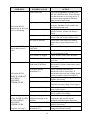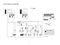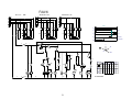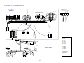
1
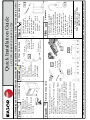
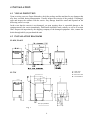
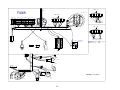
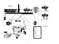
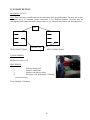
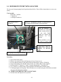
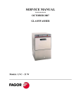
SERVICE MANUAL ********** October 2007 UNDERCOUNTER & ALL PURPOSE DISHWASHERS Models: FI – 48 W FI – 64 W FI – 72 W 0 TABLE OF CONTENTS 0 TABLE OF CONTENTS ________________________________________________________ 1 1 QUICK START GUIDE _________________________________________________________ 1 2 QUICK INSTALLATION _______________________________________________________ 2 3 SPECIFICATIONS _____________________________________________________________ 3 3.1 MODEL: FI-48 W__________________________________________________________ 3 3.2 MODEL: FI-64W __________________________________________________________ 4 3.3 MODEL: FI-72W __________________________________________________________ 5 4 INSTALLATION ______________________________________________________________ 6 4.1 VISUAL INSPECTION _____________________________________________________ 6 4.2 INSTALLATION DIAGRAMS _______________________________________________ 6 4.3 DATA PLATE ____________________________________________________________ 7 4.4 POSITIONING ____________________________________________________________ 7 4.5 WATER INSTALLATION___________________________________________________ 8 4.6 WATER DRAINAGE_______________________________________________________ 9 4.7 ELECTRICAL CONNECTION _______________________________________________ 9 5 INSTALLATION CHECKLIST__________________________________________________ 12 6 OPERATIONS _______________________________________________________________ 13 6.1 WASHING ______________________________________________________________ 13 6.2 DRAINING AND CLEANING ______________________________________________ 14 6.3 DETERGENT CONTROL __________________________________________________ 15 6.4 PREPARING THE WARE __________________________________________________ 16 6.5 DELIMING ______________________________________________________________ 16 7 TROUBLESHOOTING ________________________________________________________ 17 8 ELECTRICAL DIAGRAMS ____________________________________________________ 20 9 WIRING SCHEMATICS _______________________________________________________ 23 10 ELECTRICAL DIAGRAMS (MACHINES BEFORE MAY 2006) ______________________ 29 11 SCHEMATICS (MACHINES BEFORE MAY 2006) _________________________________ 31 12 SEQUENCE FLOW CHARTS (MACHINES BEFORE MAY2006) _____________________ 33 12.1 TIMER WIRING SCHEMATIC______________________________________________ 33 12.2 START SWITCH _________________________________________________________ 33 12.3 THERMO-STOP (HOT WATER ASSURANCE) ________________________________ 35 1 12.4 SELECTOR SWITCH (IG)__________________________________________________ 35 12.5 SAFETY PRESSURE SWITCH______________________________________________ 35 13 SERVICE PROCEDURES ______________________________________________________ 38 13.1 TANK THERMOSTAT ____________________________________________________ 38 13.2 WATER VALVE _________________________________________________________ 38 13.3 BOILER THERMOSTAT___________________________________________________ 39 13.4 TIMER _________________________________________________________________ 39 13.5 START BUTTON _________________________________________________________ 40 14 DETERGENT PUMP NEW LOCATION __________________________________________ 41 15 PROCEDURE TO INSTALL EXTERNAL CHEMICAL PUMP ________________________ 42 16 THEMOSTAT CONFIGURATIONS (AFTER OCTOBER 2006) _______________________ 43 17 RECOMMENDED SPARE PARTS_______________________________________________ 45 18 WARRANTY GUIDELINES ____________________________________________________ 46 WARNING: Improper installation, adjustment, alteration, service or maintenance can cause property damage, injury or death. Read this manual thoroughly before installing or servicing this equipment. We recommend all service performed by an authorized service technician. Follow the instructions and guidelines to ensure that your warranty remains in effect. 2 Level Dishwasher x x x x x x x Electrical Connection Single Phase Fig. 5 Data Plate (located on the right side lower panel) Fig. 1 Three Phase Fig. 6 Fig. 3 To Dishwasher: 90˚ side plus gasket To Wall: Straight side + filter x 3/4”fitting (3/4” Garden hose adapter supplied if needed) Hot Water Connection Fig. 4 Min. 140˚ F (60˚C) @ 20 psi flow pressure x Use 5’ flexible water supplied hose (Fig. 1) x Install filter and gasket supplied x Second Chemicals x Use Commercial Grade, High Temperature, Low Suds Liquid Detergent! Dishwasher comes standard with built-in Adjustable Detergent and Rinse Pumps x On the back of the Dishwasher, locate clear tube marked as “Detergent” and place inside detergent container. (Fig. 7) x The unmarked clear tube is to be placed inside your rinse container. (Fig. 7) x Contact Fagor to install an External Chemical Pump Fifth Fig. 7 Fig. 2 Drain Hook Up Open Drain required 1-1/2” minimum I.P.S. Use grey flex drain supplied (Fig. 2). Clamp it, so remains in place. x Max. Drain Height LVC-21W - 26-3/4” FI-48/64W - 31-1/2” FI-72W - 10” x x x Third Run Machine to verify that all electrical, water and drain hookups are correct, chemicals amount are adequate and there are no leaks! Remove Top and back panel to access to terminal block (Fig. 3) Check Data Plate (Fig. 4) to verify Voltage and Phase. Verify Terminal Block Connection. Single Phase (Fig. 5). Three Phase (Fig.6) When power cord is supplied, verify the connection has not be loosen upon shipment. Check Amps Consumption on Data Plate to size breaker correctly. Replace the back and top panel. Careful not pull out any wires. Write the Model and Serial number in the manual and keep in a safe place. Fourth x Place Dishwasher in permanent location x Level Dishwasher with 4 leveling feet x Level front to back and side to side First All Plumbing and Electrical Connections must be made by a qualified installer in accordance with your state and local codes! LVC-21W / FI-48W / FI-64W / FI-72W Quick Installation Guide 3 SPECIFICATIONS 3.1 MODEL: FI-48 W PERFORMANCE/CAPACITIES Capacities Racks per hr.: 22 Dishes per hr.: 550 Glasses per hr: 792 Tank: 6.6gal. / 24.9 liters Heating Elements Electric wash tank heater: 2.8 Kw Electric booster heater: 2.8 Kw Water Consumption / Requirements Gallons per hr. (Max. use): 27gal. / 102 liters Gallons per cycles: .9 gal. / 3.4 liters Inlet temperature: 140ºF Flow rinse pressure: 15-25 psi Operating Cycles Wash time (Seconds):2 settings (100,160) Dwell (Seconds): 5 Rinse time (Seconds): 15 Total Time (Seconds): 2 settings (120,180) Wash Pump Motor Motor (hp): 1 hp Dimensions / Shipping Width: 24 1/4” / 616 mm Depth: 27 1/2” / 698 mm Height: 38 1/2” / 978 mm Max clearance for dishware: 12 ½” / 318mm Rack: 20” x 20” / 500mm x 500mm Shipping weight: 160 lbs. / 73 kg Shipping volume (cu. ft.): 15 Temperatures Wash: 150ºF / 66ºC Rinse: 190ºF / 88ºC TECHNICAL SPECIFICATIONS Total Power Consumption Volts/hz/ph. Amps Power (KW) 208/60/1 14.9 3.1 220/60/1 15.9 3.5 240/60/1 17.0 4.1 Boiler Power Consumption Volts/hz/ph. Amps Power (KW) 208/60/1 12 2.5 220/60/1 12.7 2.8 240/60/1 13.75 3.3 Pump Power Consumption Volts/hz/ph. Amps Power (KW) 208/60/1 2.4 .5 220/60/1 2.7 .6 240/60/1 2.9 .7 3 3.2 MODEL: FI-64W PERFORMANCE/CAPACITIES Capacities Racks per hr.: 35 Dishes per hr.: 875 Glasses per hr.: 1260 Wash Tank: 6.6gal. / 24.9 liters Heating Elements Electric wash tank heater: 2.8 Kw Electric booster heater: 6 Kw Water Consumption Gallons per hr. (Max. use): 36 gal. / 139 liters Gallons per cycles: .9 gal. / 3.4 liters Inlet temperature: 140ºF Flow rinse pressure: 15-25 psi Operating Cycles Wash time (Seconds):2 settings (70,160) Dwell (Seconds): 5 Rinse time (Seconds): 15 Total Time (Seconds): 2 settings (90,180) Wash Pump Motor Motor (hp): 1 hp Dimensions / Shipping Width: 24 1/4” / 616 mm Depth: 27 1/2” / 698 mm Height: 38 1/2” / 978 mm Max clearance for dishware: 12 ½” / 318mm Rack: 20” x 20” / 500mm x 500mm Shipping weight: 160 lbs. / 73 kg Shipping volume (cu. ft.): 15 Temperatures Wash: 150ºF / 66ºC Rinse: 190ºF / 88ºC TECHNICAL SPECIFICATIONS Total Power Consumption Volts/hz/ph. Amps Power (KW) 208/60/3 16.6 6.0 220/60/3 17.6 6.7 240/60/3 19.0 7.9 Pump Power Consumption Volts/hz/ph. Amps Power (KW) 208/60/3 1.3 .5 220/60/3 1.6 .6 240/60/3 1.7 .7 Boiler Power Consumption Volts/hz/ph. Amps Power (KW) 208/60/3 15.0 5.4 220/60/3 15.7 6.0 240/60/3 17.1 7.1 Total Power Consumption Volts/hz/ph. Amps Power (KW) 208/60/1 28.8 6.0 220/60/1 30.4 6.7 240/60/1 32.9 7.9 Pump Power Consumption Volts/hz/ph. Amps Power (KW) 208/60/1 2.4 .5 220/60/1 2.7 .6 240/60/1 2.9 .7 Boiler Power Consumption Volts/hz/ph. Amps Power (KW) 208/60/1 25.9 5.4 220/60/1 27.2 6.0 240/60/1 29.5 7.1 4 3.3 MODEL: FI-72W PERFORMANCE/CAPACITIES Capacities Racks per hr.: 35 Trays (Dishes) / per hr.: 280 (875) Glasses per hr.: 1260 Wash Tank: 6.6gal. / 24.9 liters Heating Elements Electric wash tank heater: 2.8 Kw Electric booster heater: 6 Kw Water Consumption Gallons per hr. (Max. use): 36 gal. / 139 liters Gallons per cycles: .9 gal. / 3.4 liters Inlet temperature: 140ºF Flow rinse pressure: 15-25 psi Operating Cycles Wash time (Seconds):2 settings (70,160) Dwell (Seconds): 5 Rinse time (Seconds): 15 Total Time (Seconds): 2 settings (90,180) Wash Pump Motor Motor (hp): 1 hp Dimensions / Shipping Width: 24 1/4” / 616 mm Depth: 27 1/2” / 698 mm Height: 52” / 1320 mm Max clearance for dishware: 16 ½” / 420mm Rack: 20” x 20” / 500mm x 500mm Shipping weight: 180 lbs. / 82 kg Shipping volume (cu. ft.): 20 Temperatures Wash: 150ºF / 66ºC Rinse: 190ºF / 88ºC TECHNICAL SPECIFICATIONS Total Power Consumption Volts/hz/ph. Amps Power (KW) 208/60/3 16.6 6.0 220/60/3 17.6 6.7 240/60/3 19.0 7.9 Pump Power Consumption Volts/hz/ph. Amps Power (KW) 208/60/3 1.3 .5 220/60/3 1.6 .6 240/60/3 1.7 .7 Boiler Power Consumption Volts/hz/ph. Amps Power (KW) 208/60/3 15.0 5.4 220/60/3 15.7 6.0 240/60/3 17.1 7.1 Total Power Consumption Volts/hz/ph. Amps Power (KW) 208/60/1 28.8 6.0 220/60/1 30.4 6.7 240/60/1 32.9 7.9 Pump Power Consumption Volts/hz/ph. Amps Power (KW) 208/60/1 2.4 .5 220/60/1 2.7 .6 240/60/1 2.9 .7 Boiler Power Consumption Volts/hz/ph. Amps Power (KW) 208/60/1 25.9 5.4 220/60/1 27.2 6.0 240/60/1 29.5 7.1 5 4 INSTALLATION 4.1 VISUAL INSPECTION Upon receiving your new Fagor dishwasher, check the package and the machine for any damages that may have occurred during transportation. Visually inspect the exterior of the package. If damaged, open and inspect the contents with the carrier. Any damage should be noted and reported on the delivering carrier’s receipt. In the event that the exterior is not damaged, yet upon opening, there is concealed damage to the equipment notify the carrier immediately. Notification should be made verbally as well as in written form. Request an inspection by the shipping company of the damaged equipment. Also, contact the dealer through which you purchased the unit. 4.2 INSTALLATION DIAGRAMS FI-48W, FI-64W A = Water inlet D = Drain hose E = Electrical Cable R = Terminal Block FI-72W Min.clearance 2 1/2" R T R 42 3/4" 23 1/2" A 15" ó 18" 25" ó 28" E 8 1/2" 2" 12" Drain pump instalation Fig. 1 6 14 1/2" D 7 2/3" ó 10 2/3" 46 1/2" ó 49 1/2" 16 1/2" 23 1/4" 4.3 DATA PLATE The data plate in located on one side of the machine. Under no circumstances should the data plate be removed from the unit. The data plate is essential to identify the particular features of your machine and is of great benefit to installers, operators and maintenance personnel. It is recommended that, in the event the data plate is removed, you copy down the essential information in this manual for reference before installation. Any transformations or changes made on the machines during installation should be reflected on the data plate or using a label as below: Total load at indicated voltage 4.4 POSITIONING Leveling and adjusting the height of the appliance is done by turning the leveling stands (Fig. 2) to the desire height. Ensure that the unit is level (front to back, side to side) before making any connections. FI-72W FI-48W FI-64W Fig. 2 7 4.5 WATER INSTALLATION Water installation is carried out as shown in figures 3 and 4. The hot water line to the dishwasher must provide between 20±5 psi of water pressure. The hot water heater should be set to deliver ≥140°F water temperature to the dishwasher for best results. Use ¾” copper tubing inlet line. S = Gate valve F = Filter H = Hose E = Fill valve M = Pressure gauge R = ¾” Copper Fig. 3 CAUTION: Do not confuse static pressure with flow pressure. Static pressure is the line pressure in a “no flow” condition (all valves and services are closed). Flow pressure is the pressure in the fill line when the solenoid valve is opened during the cycle THE DISPLAY OF THE PRESSURE GAUGE SHALL BE CLEARLY VISIBLE OF THE OPERATOR OF THE MACHINE. THE GAUGE SHALL HAVE INCREMENTS OF 1 psi (7 kpa) OR SMALLER AND SHALL BE ACCURATE TO ±2 psi (±14 kpa) IN THE 15-25 psi (103-172 kpa) RANGE. IF THE GAUGE IS LOCATED UPSTREAM OF THE CONTROL VALVE, IT SHALL BE MOUNTED IN AN ACCESSIBLE VALVE WITH A ¼ IN IRON PIPE SIZE CONNECTION. . 2 If the water pressure is less than 20 psi (1.4 kg/cm ), installation of a water pump is required as shown in Fig. 4. In areas where the pressure fluctuates or is greater than the recommended pressure, it is suggested that a water pressure regulator be installed. S = Gate valve F = Filter H = Hose E = Fill valve B = Electro pump M = Pressure gauge R = ¾” Copper Fig. 4 It is necessary to remove all foreign debris from the water line that may potentially get trapped in the valves or cause an obstruction, prior to connecting to the machine. Use only the supplied hoses (3/4” Female hose connector) at the water connections. Failure to do so may result in damage to the solenoid valve threads and leaking. Tighten by hand. Connect the bent side of the hose to the machine. Adaptor supplied for ¾” female garden hose connection. FOR HARD WATER SUPPLIES WITH A HARDNESS OF OVER 2 GRAINS OR 10ºF AND PH BEYOND THE RANGE OF 7.0 – 8.5, A WATER CONDITIONER MUST BE INSTALLED. Slowly turn on the water supply to the machine after the incoming fill line and the drain line have been installed. Check for any leaks and repair as required. All leaks must be repaired prior to placing the machine in operation. 8 4.6 WATER DRAINAGE Attach the drain hose as shown in Fig. 5. It is recommended to affix a siphon pipe to prevent odors. All piping from the machine to the drain must be a minimum 1-1/2” I.P.S. There should also be an air gap between the machine drain line and the drain. For natural overflow efficiency use floor drain. 2 3/8" D = Drain hose C = Drain collector A = Air Gap F = Scrap Basket Fig. 5 4.7 ELECTRICAL CONNECTION − To access to the electrical terminal block (R) (Fig. 1), remove the top cover (T) (Fig. 1) and the rear panel (P) (Fig. 1). Connect the wires as shown in figure 6. Insert the power cord through the cord holder (E) (Fig. 1) and make sure to leave enough cable to remove the electrical panel from the front for service. Tighten the connections. − Leave free ≥ 39” (≥ 1000 mm) of power cord from the rear to facilitate cleaning of the location of the dishwasher. − Install a circuit breaker in accordance to required consumption guidelines and data plate. − The machine must be grounded. WARNING: Electrical Shock Hazard It is the personal responsibility and obligation of the customer to contact a qualified electrician to assure that the electrical installation is adequate and is in conformance with the National Electrical Code, ANSI / NFPA 70 – latest edition and all local codes and ordinance. 9 FI-64W / FI-72W 208-220 volts / 1 phase Ground Line 5 Line 4 Bridge Blue Cap White Wire Blue Cap Red & White Wires 3 2 1 Black Cap White Wire Black Cap White Wire Gray Cap (2) White Wire Gray Cap White Wire Brown Cap Red & White Wires Brown Cap White Wire Note: Bridge may have a Brown wire Clear Cap Yellow / Green Wire 10 Other wiring configurations used BEFORE May 2006: 11 5 INSTALLATION CHECKLIST CHECK OFF THE FOLLOWING ITEMS AS THEY ARE COMPLETED BEFORE PROCEEDING TO OPERATE OR SERVICE THE DISHWASHER. Has the dishwasher been checked for concealed/hidden damage? Has the dishwasher been properly leveled? Has the service voltage been checked to ensure that it meets the requirements listed on the dishwasher data plate? Has the dishwasher circuit breaker/service breaker been sized correctly, given the dishwasher’s amperage requirements? Has the dishwasher been properly grounded? Are the electrical connections and pipes tighten and remain in place? Is the water valve open? Is the incoming water supply at 15 - 25 psi? Has been installed with the supplied water hose? Is the water hose not kinked? Has the incoming water supply been flushed for debris? Is the hot water supply at the optimum temperature (140ºF)? Is the water hardness ≤2.0gpg/34.2ppm and PH level 7 - 8.5ph ? Has the drain plumbing been installed according to the instructions in this manual? Is the drain hose not kinked? Is the overflow tube with the O-ring fitted in its position inside the tank Is the detergent for commercial dishwashers? Have you adjusted the amount of detergent / rinse going to the machine? MODEL NO.___________________________ SERIAL NO.___________________________ INSTALLATION DATE _________________ SERVICE REP. NAME __________________ PHONE Nº ____________________________ 12 6 OPERATIONS 6.1 WASHING Fig. 7 Control Panel • • Set selector switch (1) to desired time setting. (FI-48W, 120 or 180 Second / FI-64W & FI72W, 90 or 180 Second) This will turn your machine ON. Indicator light (2) will illuminate. Machine will automatically begin to fill and heat the water in the boiler and tank to the proper temperatures. Wait for the rinse gauge (3) to read ≥ 180º F (83˚C) and your wash tank gauge (4) to read ≥ 150º F (66˚C). (Time will vary depending on incoming water temperature) Note: To speed up the warm up process, you can run the Dishwasher a couple of times only after the Rinse Gauge (3) is ≥ 180º F (83˚C). • • • • Open the door, load your dishwasher and close the door. Start the wash by pressing and holding your start button (5) until your machine begins to wash. Start switch (5) will illuminate during operation. Wash is completed when the start button (5) turns off. Open the door and repeat process. If you start your dishwasher prior to your booster heater (3) reaching a minimum of 180º F (83ºC), YOU WILL HAVE AN EXTENDED WASH CYCLE! 13 6.2 DRAINING AND CLEANING Draining must occur EVERY DAY and if in a high application; It should be drained after each meal rush! Fig. 7 Control Panel • • Switch selector switch (1) to the 0 setting. (OFF) (Fig. 7) Open the door and remove the Front Right S/S Filter. (Fig. 8) • Remove the overflow tube by inserting a finger into the top of the tube. (Fig. 9) • • • • • • • • • • DO NOT REMOVE SCRAP BASKET! DO NOT LOOSE O’RING! Close the door. Set selector switch (1) to for drain. (Not shown of FI-72W, it will drain when you pull the overflow tube) Depress the Start Button (5) to start the drain pump. Start Button (5) will illuminate. (FI-48W / FI-64W only) Wait until the Start Button (5) turns off. (3 minutes) Open door. Take out scrap basket for cleaning by twisting to the left. (Fig. 10) Replace scrap basket, lock into position by twisting to the right and replace overflow tube with O-ring. Replace S/S filter back into position. (Fig. 8) Switch selector switch (1) back to the OFF position. Wipe clean and dry the machine if the day is completed. Leave door open until the next day’s operations or to one of the time settings to begin using the machine again. 14 6.3 DETERGENT CONTROL • • • • • • • • Use Commercial Grade, High Temperature, Low Suds Liquid Detergent. Fagor doesn’t recommend any specific brand name of chemicals. Contact your local chemical distributor for questions concerning your chemical needs. All machines come equipped with an internal Detergent and Rinse dispenser. Take the tube located in the back or your machine clearly marked “Detergent” and place inside detergent container. Take the tube with no markings and place inside rinse container. Tubes are clear to provide you a visible means that chemicals are being dispensed. If desired you can control the amount of Chemical being dispensed by opening the bottom front panel of the machine. Locate the detergent dispenser (Fig. 9) and regulate according to the flow chart (Fig. 9a). For the Rinse, turn the button counterclockwise to get more rinse aide and clockwise for less. You prime the line by pressing the button. Verify all connections to the dispenser are hand tighten to prevent any leaks. Control and maintain the level of detergent and rinse aid of the tanks. Keep pipe and filters submerged. Detergent Controller 220º 7 6 Oº 1 2 3 5 4 Fig.9a Fig. 9 1 2 3 4 5 6 7 Gal./h. 0 0.06 0.20 0.40 0.53 0.66 0.80 Rinse Controller and priming button Warning! If you require the installation of an NON FAGOR Detergent and Rinse pump, a form MUST be fill out prior to installation by your installer. Failure to do so, will void your Warranty. This form can be located inside your dishwasher. If lost, please contact Fagor to get a copy. 15 6.4 PREPARING THE WARE - Pre Rinse all racks prior to placing them in the dishwasher to remove large food particles from the ware. - Wash glassware first - Put trays in the baskets, making sure is in its separate rack (Fig.12). - Put plates in the baskets, making sure each is in its separate rack (Fig. 11). - Put glasses in upside down. - Put cutlery in the cutlery baskets handles down. Mix spoons with knives and forks. (Fig. 10) - Put the special cutlery baskets in the base baskets. Fig. 10 Fig. 11 Fig.12 6.5 DELIMING In order to maintain dishwasher at optimum conditions, it is requested to remove lime and corrosion deposits on a frequent basis. A deliming solution should be available from your chemical supplier. Read and follow all instructions on the label of the deliming solution. Operations: • • • • • • • Fill the machine. Add the correct amount of deliming solutions as recommended by the deliming solution manufacturer. The water capacity of the tank can be verified on the specification sheet of this manual Remove detergent and rinsing tubes from containers so no chemicals go to the machine Run the machine for the recommended period of time. As many cycles as needed. Turn off the machine and open the door When clean, drain and re-fill the machine Run machine for 3-4 cycles to remove deliming solution Drain the machine. 16 7 TROUBLESHOOTING First be sure that the “INSTALLATION CHECKLIST” in this manual was completed and check out that all the conditions still remains in effect. For support or further service information contact Fagor Service Department toll free at 1-866-GO-FAGOR (46-32467). The diagnosing, testing and repair of any electrical, mechanical device is to be performed solely by trained service technicians. SYMPTOM POSSIBLE CAUSE Dishwasher will NOT FILL after the door is closed. Power “ON” light (L1) is not illuminated. Service breaker tripped Dishwasher will NOT FILL after the door is closed. Power “ON” light (L1) is illuminated. No water to machine Machine not connected to power source. Faulty selector switch (Ig) Fill pressure switch’s pipe clogged Faulty fill pressure switch (P1) Start button (St) faulty Verify the wiring of the switch; if correct, replace the switch. (Position 4-4a / 8-8a) Verify position change 1-2 / 1-3 to pressure switch. Possibly stuck . Verify the wiring and voltage received; if correct replace fill valve. Drain the unit, fill again, even manually and run a cycle Verify it changes position of the switch; If not replace it. Verify start button is operating properly. If not replace it. Faulty Timer (M) Verify the timer is rotating (M1, M2 & M3). If not, check to see that the motor is receiving power. If so, replace the timer assembly. Ohm out timer motor leads. Faulty wash pump (MBL) Verify that the wash pump is getting power. If so, replace the pump. Ohm out windings. Verify voltage at (1,2 to1a) at selector switch Wait until sanitized rinsing temperature is reached (195ºF). Check out your incoming water temperature. Selector switch faulty (IG) Dishwasher RUNS continuously in the wash cycle or not rinsing. Reset. If the breaker trips again, contact an electrician to verify amps or possible short. Verify the unit is connected to a hot (live) feed. Verify voltage and proper phasing. Verify hose is not blocked or kinked, water valve is open and pressure > 20 PSI. Machine not level Level machine. Legs are height adjustable. Overflow tube not attached Check condition of overflow tube. or broken / missing O-ring. Faulty door switch Verify the wiring of the switch; if correct, replace the switch (Ip) or the door relay (Rp) Faulty fill pressure switch (P1) Faulty fill valve (V) Dishwasher will NOT RUN after the door is closed. Power “ON” light (L1) is illuminated and the unit has completed the filling and heating cycle. ACTION Rinsing temperature gauge is lower than 195ºF. (Continue next page) 17 SYMPTOM POSSIBLE CAUSE ACTION Timer faulty (M) Dishwasher RUNS continuously in the wash cycle or not rinsing. Dishwasher FILLS slowly and/or rinse is weak. Verify the programmer is rotating (M1, M2, M3, and M4 & M5). If not, check to see that the motor is receiving power. If so, replace the programmer assembly. Ohm out timer motor leads. Operating t-stat faulty (Tc) Verify position change if temperature has been met. Opening circuit to tank relay and closing thermo relay. Faulty thermo relay (R) Verify thermo-relay is not energized and (pk/pk) from m1 to timer run motor is closed Faulty rinse valve (V) Verify the wiring and voltage received; if correct, ohm out. If open replace valve. No water to machine. Verify hose is not blocked or kinked, water valve is open and pressure > 20 PSI. Clogged or obstructed Remove and clean rinse arms/nozzles. rinse arms Poor water pressure Verify the inlet water pressure is at a min of 15 psi and max 25 psi. Hose strainer is clogged Check strainer or any filters installed. Bad fill valve (V) Temperature gauge in front panel is defective. Misadjusted/faulty thermostat (Tc) Dishwasher RUNS. RINSE WATER NOT REACHING REQUIRED TEMPERATURE. Faulty high limit stat (Tl) Faulty heater relay (Cc) Rinse heater (Rc) faulty Dishwashing machine RUNS. WASH WATER NOT REACHING REQUIRED TEMPERATURE. (Continue next page) Valve can be clogged or lazy, causing poor flow. Check temperature with a calibrated thermometer. Replace temperature gauge if necessary. Verify operation and setting of thermostat; replace if necessary. If thermostat is not receiving voltage, check wiring or replace selector switch (IG) Reset thermostat, depressing red button. Replace if necessary. Ohm out booster relay, closed when solenoid receiving voltage. If not replace. Ohm out element check for continuity; if open, replace heater. Bad selector switch (IG) Verify voltage between positions (6/6a) (Pk/r); replace if no voltage. Wrong incoming water Check out that incoming water and pressure going to the temperature and pressure are the machine. optimums indicated on the data plate. Faulty operation t-stat (Tc) Verify position change to tank t-stat (Tt); replace if necessary. Misadjusted/faulty Verify voltage to t-stat and position thermostat (Tt) change from booster to tank. 18 SYMPTOM Dishwashing machine RUNS. WASH WATER NOT REACHING REQUIRED TEMPERATURE. Dishwasher RUNS perfectly but NOT DRAINING. Dishes are not coming out clean enough. POSSIBLE CAUSE Tank heater relay (Ct) faulty. Verify contacts are close when there is voltage to relay also check for stuck or pitted contacts. Rinse heater (Rt) faulty Check element for continuity; if open, replace heater. Overflow tube not removed. Check and remove. Drain pump (BD) clogged. Open drain pump cover and remove debris. (Lower front panel; unscrew white removable cover, rotate c/cw) Make sure the drain hose is not kinked Drain hose kinked Drain pump (BD) faulty Verify voltage to drain pump; if receiving voltage, ohm out drain pump if open, replace it. Faulty safety pressure Verify position changes from (1-3 to-1-2) switch (P2) Machine temperatures or pressure may not be to specification. None or too little detergent being used. Verify that the water pressure is at a min. of 20psi and max 60 psi. The water temperature should be at the recommended 140 F. Make sure detergent to dish ratio is fallowed to manufacturer specification. Improper loading or overloading Read chapter on proper loading of dishwasher. Washing and or rinsing arms jammed or dirty. Check that arms rotate properly, and that rinsing and washing nozzles are not blocked or dirty. Clean if necessary Remove instruction form the pump or from the pipe Clogged drain WATER OVERFLOW FROM BOTTOM OF THE DOOR ACTION Machine not level Level machine. Increase height to the front Excessive inlet pressure Install pressure reducing valve. Ensure flow is 15-25 PSI DETERGENT FOAMING Use detergent for commercial appliances. Reduce detergent quantity 19 8 ELECTRICAL DIAGRAMS 208-220-240 V. 1Ph R g m N n a a g Ct g a Rt 380 - 415 V. n R g S T m N a a n a n a Cc g Ct g a Rt Rc FI - 48 W 3NPh a 180sec n Cc n a M1 160s M2 Wash 15s Rc M3 Rinse 5s 2" M4 Termo-Stop 60s 120sec.Program. M5 2 m m 4 4a 1 r a n P1 Cp 5 6 5a 120 M1 6a n IG rs rs rs Tc vi TSTP 1a 3a na am Cp Ct r b b Cc1 Cc2 M Av.R M 2a MBL g 7a 1 n rs vi BD 7 IG 1 1a 2 2a Ds Det. V 8 8a ve ve 20 ve 4 4a 5 5a X X 6 6a 7 7a 8 8a X 0 120 X 180 X a a 3 3a X P2 C L2 g 3 2 M4 vi L1 Cp 3 TSC m 1 2 Cc 180 M3 am vi na Tt M2 M5 St na Ip 0 m r 3 Z-228444000 X X X X X X X X X FI-64 W 380 - 415 V. 208-220-240 V. 3Ph 3NPh 208-220-240 V. 1Ph R n S m g T R n S m g T N a R m N a m g a g Ct Cc1 a g Rt n g a g m n Ct Cc2 r g rs b m g m n Cc1 a g g m n m g a g Ct Cc2 g rs b r Rt Rc n m n Cc1 a g g 180sec m n M1 Cc2 r Rt Rc n 160s g rs b Wash M2 m n 15s M3 Rc Rinse 5s 2" M4 Termo-Stop 90s Fast got to 90sec.Progr. 90sec.Program. M5 2 m m 4 4a 1 r a n P1 Cp 5 6 5a 6a n IG rs M5 St vi 1a 3a am 8 8a ve b b Cc1 Cc2 M Av.R M ve 21 2a MBL a g 7a 1 n rs vi BD 7 IG 1 1a 2 2a 3 3a X P2 C L2 g 3 2 na a r M4 vi Ct Cp 1 2 Cc1 3 TSC m am vi na Tt Cp M3 TSTP na 180 rs M2 Tc L1 90 M1 rs Ip 0 m r 3 Ds Det. ve 5 5a X X 6 6a 7 7a 8 8a X 0 90 V 4 4a 180 X X Z-258439000 X X X X X X X X X FI-72W 380 - 415 V. 3NPh 208-220-240 V. 3Ph 208-220-240 V. 1Ph R n S m g T R n S m g T N a R m N a m g a g Ct n Cc1 a g Rt g a g m n Ct Cc2 r m g g rs b m n Cc1 a g g m n g m n rs b m g a g Ct Cc2 r Rt Rc n Cc1 a g Rt Rc n g m n g m n 180sec M1 Cc2 r rs b 160s M2 Wash 15s M3 Rc 5s 2" M4 Termo-Stop 90s Fast got to 90sec.Progr. M5 2 m m 3 3a 1 r a n m 3 0 P1 Cp M1 90 IG n rs rs rs 180 TSTP Tc na Ip M5 St am M4 Ct a 2 2a Cc1 na Cc2 IG Cp b 1a b L1 Cp m 1 TSC vi M3 Cc1 na vi Tt M2 MBL a M ve ve 22 180 n L2 M Av.R EB Ds Det. V ve 1 1a 2 2a 3 3a X X X X X 0 90 rs C Rinse Z263005000 90sec.Program. 9 WIRING SCHEMATICS 1 FI-48W 4 380/415 V - 3N ~ Z-208436 1 4 60HZ Z-228412 208/220/240 V - 1N~ 1 6 seg. na 4 g m g g a A2 a rs ve vi ve a1 b1 a NC NC b A1 A2 ve P1 3 1 1 r m 4 3 1 1 2 r 1 2 4 4 3 2 4 3 1 1 3 1 1 1 1 2 2 Z-2 030 05 P2 4 rs vi am m g n a a n 3 2 rs/g Z-203074 3 3 1 1 Z-243046 1 2 2 2 2 Z-253046 3 1 1 1 2 2 3 1 b 3 1 1 3 3 1 2 1 2 2 M2 a a m g n M1 Com ve 3 2 a rs 180 seg. 1 M3 rs na am 4 4 3 1 2 1 m N T S R 2 vi 4 2 1 1 1 r n N T S R M4 e n CC1 A1 rs b 3 am/ve Cp 4 M5 rs R-253044 1 am /v a Z-213007 am a n Z-743009 Z-203023 Ct Z-203062 n W Com 2 rs 2 Z-203009 1 a Ip ve 8 5 7a rs 6 4 8a g g 7 n 1 1 1 TMC TMT ºF Z-273060 1 1 W 2 Z-213033 1 n 5a r m na na am 3 2 vi b 1 Z-223001 6a 4a 3a g ve r 1 ve a 2a L1 1a na ST rs R-693056 IG ve L2 Q-578006 Z-701135 rs V ve am/ve 1 4 1 MB 1 4 1 n b 1 C 1 60HZ W Z-203511 V-32130 1 am/ve 4 1 Z-203601 Rt 1 rs b ve ve am/ve g a 4 1 1 1 4 4 TSC am/ve TMC rs b 1 4 2 Z-203014 (EGO) Tstp Rc m TC m 1 1 1 1 4 Z -20 1 1 1 1 1 Z228443000 Ds Det. 890 4 vi 4 rs na vi 1 4 2 Z-203014 (EGO) am 2 Z-203014 g 4 (EGO) Tt na 1 cortar Tc 60HZ W vi TSC vi Z-213014 Z-201706 ve Z-208903 B.D. Z-223501 23 n: black a: blue r: red b: white g: grey m: brown na: orange ve: green vi: violet rs: pink am/ve: yellow/green am: yellow 1 FI-48W 4 380/415 V - 3N ~ Z-208436 1 60HZ Z-228412 50HZ Z-213002 4 220/240 V - 1N ~ 1 na 4 Cp CC1 A1 g g a a a A2 rs ve vi NC ve a1 b1 P1 A1 NC b A2 ve 1 4 4 1 2 r 1 2 4 3 3 1 r m 4 2 2 4 3 1 1 3 1 1 1 2 2 Z-2 4 2 rs/g na 03 00 5 vi am m g n a a rs n a rs Z-203074 3 3 1 1 Z-243046 1 2 2 2 2 Z-253046 3 1 1 3 1 1 2 2 3 b 3 1 1 3 1 2 1 2 2 M2 a a m g n M1 Com ve 3 2 N T S R M4 M3 rs 180 seg. 3 1 m N T S R 2 am P2 4 4 3 1 2 1 1 1 vi rs b 3 1 1 1 4 r n 3 M5 rs R-253044 e n Z-213007 am a g m 1 am/v a n Z-743009 am/ve Z-203062 n Z-203023 Ct W B-A Com 6 seg. 2 rs Z-203009 2 1 1 1 1 1 1 1 a ve 8 g g 7 g Ip 6 ve TMC ve r ºF Z-273060 L1 n 5 a TMT rs 4 m na 3 W 2 Q-578006 R-693056 vi 1 Z-223001 8a na am b Z-203080 4a 3a LIGHT-LED n 6a 5a r 2 7a ST na rs ESQUEMA TEORICO FI-48W Z-228444 LEYENDA INDICADOR DE COMPONENTES Z-243051 Z-713034 L2 1 2a 1a ve IG Z-701135 V ve rs am/ve 1 4 1 MB 1 4 1 n b 1 C 1 50HZ B-A Z-201011 60HZ W Z-203511 V-32130 1 am/ve 4 1 Z-203601 Rt 1 rs b ve ve am/ve g a 4 1 1 1 4 4 TSC am/ve TMC rs b 1 4 2 Z-203014 (EGO) Tstp Rc m TC m 1 1 1 1 1 4 Z-20 1 1 1 1 Ds Det. 89 04 vi 4 rs na vi 1 4 2 Z-203014 (EGO) am 2 Z-203014 g 4 (EGO) Tt na 1 cortar Tc vi TSC vi Z-213014 Z-201706 ve Z-208903 B.D. Z228443000 50HZ B-A Z-220901 60HZ W Z-223501 24 HC-17992-1 1 4 230 V - 3 ~ Z-208436 1 4 60HZ Z-258412 1 400 V - 3N ~ 4 Cp n m g n A1 g g a m g vi b n A1 A1 rs A2 r b rs m g A2 n A2 ve a1 ve b1 ve ve P1 1 r m 1 1 1 1 2 r 2 1 4 3 1 2 P2 a n m 4 4 3 1 1 1 1 n 2 3 3 1 1 2 2 2 rs/g Z-243047 3 3 1 1 Z-243046 1 2 2 2 2 Z-253046 3 1 2 1 3 1 1 2 b 3 1 1 3 3 1 1 2 2 2 m g 1 1 1 a M2 M1 Com ve 3 2 a rs 180 seg. 4 4 3 1 rs vi am g 1 rs b 3 Z-2 030 05 4 na M4 n a M3 rs m g a n am 4 2 2 vi 1 rs m N T S R 1 r n 3 T S R M5 rs b 3 vi W Com na R-253044 1 4 Cc2 Z-213007 Cc1 Z-683087 Z-213007 am a g m am/ve a Z-203023 Ct Z-203062 6 seg. am/ve FI-64W 230 V - 1N ~ 2 rs a n N R m g nm g am/ve a 1 1 1 2 1 Z-203009 Ip a ve g g 8 7 rs 6 n 5 4 8a 7a TMC TMT ºF Z-273060 1 1 ºF Z-273060 ESQUEMA TEORICO LEYENDA INDICADOR DE COMPONENTES 2 na 3 am vi b 1 4a n 3a g r ve a L1 1a na ST 1 ve 2a Z-258439 Z-243051 Z-713034 Z-213033 1 5a r m na 2 Z-223001 6a 1 1 1 rs R-693056 IG ve L2 Q-578006 Z-701135 rs V ve am/ve 1 Z258438000 4 1 MB 1 4 1 n b 1 C 1 60HZ W Z-203511 n: black a: blue r: red b: white g: grey m: brown V-32130 1 am/ve 4 1 Z-203601 Rt 1 rs b ve ve am/ve g a 4 1 1 1 4 1 4 rs b 1 4 2 Z-203014 (EGO) Tstp m g Rc 1 1 vi rs na vi 1 4 2 Z-203014 (EGO) n am/ve TC b 1 1 1 4 TSC TMC 1 1 1 4 am 2 g 4 na 1 cortar Tc r rs ºF W Z-241703 Ds Det. Z-2 0 89 0 4 TSC vi Z-213014 Z-208903 Tt B.D. 60HZ W vi ve Z-203014 (EGO) Z-223501 25 na: orange ve: green vi: violet rs: pink am/ve: yellow/green am: yellow 1 FI-64W 4 230 V - 3 ~ Z-208436 1 4 60HZ Z-258412 400 V - 3N ~ 4 Cp n m g n b vi A1 g g a m g n A1 A1 rs A2 b r rs 3 vi m g A2 n A2 ve a1 ve b1 ve ve 1 1 1 1 2 2 1 2 r m 4 2 Z-2 P2 4 m g a n am 03 0 05 4 4 3 na a m n n rs 1 1 1 1 2 3 3 1 1 2 2 2 rs/g Z-243047 3 3 1 1 Z-243046 1 2 2 2 2 Z-253046 1 3 1 2 3 1 1 3 1 b 3 1 1 3 1 2 2 2 2 m g 1 1 1 a a M2 M1 Com ve 3 2 M4 n a M3 rs vi am g 180 seg. 4 4 3 1 rs rs 1 4 3 1 b 1 1 rs b 3 r P1 2 T S R M5 rs m N T S R 1 r n 3 na R-253044 1 4 Cc2 Z-213007 Cc1 Z-683087 Z-213007 am a g m W Com b am/ve a Z-203023 Ct Z-203062 6 seg. am/ve 1 230 V - 1N ~ 2 rs a n N R m g nmg am/ve a 2 1 a ve g g 8 7 1 1 1 1 1 1 Z-203009 Ip TMC ºF Z-273060 vi a 1 L1 Z-223001 R-693056 Z-203080 6a r na am b 1 1 2 4a ST 1a ESQUEMA TEORICO LEYENDA INDICADOR DE COMPONENTES na rs 3a 2a LIGHT-LED n 5a 2 ve ºF Z-273060 m na 3 g TMT n 5 4 ve r rs 6 1 8a 7a Z-258439 Z-243051 Z-713034 L2 1 ve IG Q-578006 Z-701135 V ve rs am/ve 1 4 1 MB 1 4 1 n b 1 C 1 60HZ W Z-203511 V-32130 1 am/ve 4 1 Z-203601 Rt 1 rs b ve ve am/ve g a 4 1 1 1 4 1 1 4 4 rs b 1 4 2 Z-203014 (EGO) Tstp m g Rc 1 b rs na vi 1 4 2 Z-203014 (EGO) n am/ve TC b 1 1 1 am 2 Z-203014 g 4 (EGO) Tt na 1 cortar Tc r rs ºF W Z-241703 Ds Det. Z-20 8 90 4 1 4 TSC TMC 1 1 60HZ W vi TSC vi Z-213014 ve Z-208903 B.D. Z258438000 Z-223501 26 HC-17991-2 1 4 230 V - 3 ~ Z-208436 1 4 60HZ Z-258412 1 6 seg. 400 V - 3N ~ 4 na Ct n Cc1 Z-683087 Z-213007 am a g m g m A1 rs g a rs A2 r Cc2 Z-213007 b vi n n rs 4 vi A1 NC b m g A1 m g A2 n A2 ve a1 ve b1 ve ve rs 3 1 1 1 1 1 P1 n rs 1 3 2 1 4 4 3 1 1 1 1 vi n m g n Z-243047 3 3 1 1 1 3 1 Z-243046 1 2 r 3 1 2 3 1 2 1 3 1 1 3 1 2 Z-243048 3 3 1 1 1 2 2 2 m 3 2 r a ve na na 3a Z-273060 230 V - 1N ~ N R m g nm g a ESQUEMA TEORICO LEYENDA INDICADOR DE COMPONENTES IG n 1 ve rs R-693056 ve L2 Q-578006 am/ve 1 n: black a: blue r: red b: white g: grey m: brown na: orange ve: green vi: violet rs: pink am/ve: yellow/green am: yellow 1 Q-578006 MB ve vi 4 n b 1 C 50HZ B-A Z-201011 60HZ W Z-203511 V-32130 1 ve 1 4 Rt 1 a 4 1 1 1 4 1 1 4 4 rs b 1 4 2 Z-203014 (EGO) Tstp m g Rc 1 1 n TC am/ve V1 Z-701135 Ds Det. 1 Z-208903 rs na vi 1 4 2 Z-203014 (EGO) am/ve b 1 4 TSC TMC Z-2 0 89 0 4 1 1 1 rs rs b ve ve am/ve g am 2 g 4 na 1 cortar Z-203014 (EGO) Tt Tc r rs ºF W Z-241703 Z-263005 Z-243051 Z-713034 na ST 4 Z-203601 1 a L1 Z-213003 1 Z-213033 g r ve 2a 2 1 1a 1 1 1 Z-273060 1 2 am/ve 1 1 Com Z-203009 2 1 M1 Ip TMT ºF g M2 1 TMC ºF m a a n 1 1 1 n a ve 3 2 a rs 180 seg. 4 4 3 1 rs b a 1 4 b 4 3 na M4 M3 rs m g a n 4 r 1 m 1 m N T S R Q-578006 am/ve Cp rs b R-253044 Z-203023 a M5 rs 1 Z-203062 T S R Com am/ve FI-72W vi TSC vi Z-213014 27 Z263006000 1 4 230 V - 3 ~ Z-208436 1 4 60HZ Z-258412 1 6 seg. 400 V - 3N ~ 4 na Ct g n m b vi n A1 rs g a rs A2 r m g n rs 4 vi A1 A1 NC b R-253044 Cc2 Z-213007 Cc1 Z-683087 Z-213007 am a g m m g A2 n A2 ve a1 ve b1 ve ve rs 3 1 1 1 1 1 P1 n rs 1 3 2 4 3 4 4 3 1 1 1 1 na vi b a m n g n rs Z-243047 3 3 1 1 1 3 1 1 Z-243046 2 r 3 1 2 1 3 1 2 3 1 1 3 1 3 3 1 1 1 2 Z-243048 2 2 2 a 2 g TMTºF TMC ºF ve r Z-273060 230 V - 1N ~ ve Z-203080 m r N R m g nm g a a ve na na 2a 1a 1 IG L1 Z-213003 ST na ESQUEMA TEORICO LEYENDA INDICADOR DE COMPONENTES rs 1 L2 ve Q-578006 R-693056 am/ve 1 4 1 Q-578006 MB ve vi 4 n b 1 C 50HZ B-A Z-201011 60HZ W Z-203511 V-32130 1 ve 1 Z-203601 4 Rt 1 rs b ve ve am/ve g a 4 1 1 1 4 1 4 rs b 1 4 2 Z-203014 (EGO) Tstp m g Rc n am/ve 90 4 am/ve V1 Z-701135 Ds Det. 1 Z-208903 rs na vi 1 4 2 Z-203014 (EGO) TC b 1 1 1 4 TSC TMC Z-2 0 8 1 1 1 1 4 rs am 2 Z-203014 g 4 (EGO) Tt na 1 cortar Z263006000 Tc r rs ºF W Z-241703 vi TSC vi Z-213014 28 1 1 LIGHT-LED n 3a a Z-273060 1 2 2 1 3 1 2 am/ve 1 1 1 Z-203009 1 M1 Com 1 Ip g M2 an 1 1 1 m a ve 3 2 M4 n a M3 rs 180 seg. 4 4 3 1 m g an rs 1 4 b 1 m N T S R Q-578006 4 r 1 m 1 rs b am/ve Cp Z-203023 a M5 rs 1 Z-203062 T S R Com am/ve FI-72W HC-17897-2 Z-263005 Z-243051 Z-713034 FI Rt Ct I G= General switch L1 = On lamp Ip = Door micro Rp = Door relay P1 = Pressure switch Tc = Drum thermostat Tt = Tank thermostat Tl = Drum limiter thermostat Cc = Drum contactor Ct = Tank contactor L2 = Machine ready light Rc = Drum heating element St = Start button FI = Interferences filter BD = Drain pump R N a m a a 29 8 4 Rc a a 8a L1 4a Cc n n Rp Ip n ve Interrupteur general Témoin de marche Micro de porte Relais de porte Presostat Thermostat du surchauffeur Thermostat de cuve Thermostat limitateur du surchauffeur Contacteur du surchauffeur Contacteur de cuve Témoin de marchine preparée Resistance du surchauffeur Bouton de márche Filtre d¨interferences Pompe de vidange r r 208-220-240 V. 1Ph 1 n P1 r Ct am Tt na rs 5 6 g r Tc Cc vi vi T 6a Rp 180 120 Tl M Av.R St M1 r Interruptor General Lampara de marcha Micro de puerta Relé puerta Presostato Termostato calderin Termostato tanque Termostato limitador de calderin Contactor calderin Contactor tanque Lampara máquina preparada Resistencia calderin Pulsador de marcha Filtro de interferencias Bomba de Desagüe 5a 3 2 0 na na vi 3a 3 M5 rs b M X X R Cc M4 rs X g C n X X ve 2 am M2 2a 1 2 MBL m 1a X X Rt = Tank heating element M.Av.R = Motor programmer rapid advance M = Motor programmer M1 = Micro programmer on M2 = Micro programmer wash M3 = Micro programmer rinse M4 = Micro programmer Termo-Stop M5 = Micro programmer 120" advance L3 = Cycle light MBL= Motor pump wash C = Motor pump condenser V = Filling and rinsing valve Ds Det = Detergent dispenser (Optional) P2 = Safety pressure switch EB = Electric pressure pump (Optional) R 180 120 0 BD 1 vi n X X P2 3 X X 1 2 3 4 5 6 7 8 1a 2a 3a 4a 5a 6a 7a 8a X X X X FI-48 W Ds Det. EB M5 M4 M3 2s 60s ±1 5s 5" Fas got to 120sec.Progr. 2" 180sec ±1 15s Resistencia tanque Motor programador Avance Rápido Motor programador Micro programador marcha Micro programador lavado Micro programador aclarado Micro programador Termo-Stop Micro programador Avance 120" Lámpara de ciclo Motobomba lavado Condensador de motobomba Válvula de llenado y aclarado Dosificador de detergente (opcional) Presostato de seguridad Electrobomba de presión (Opcional) Z-228402 HC-17118 120sec.Program. Termo-Stop Rinse 1s Wash Colours code-Code de couleurs-Codigo de colores: r = red-rouge-rojo m = brown-marron-marron g = grey-gris-gris n = black-noir-negro a = blue-bleu-azul b = white-blanc-blanco vi = violette-violet-violeta am = yellow-jaune-amarillo na = orange-orange-naranja rs = rose-pink-rosa ve = green-vert-verde am/ve = yellow green-jaune vert-amar./verde Resistance de cuve Moteur du programm. d¨ avancement rapide Moteur du programmateur Micro du programm. de marche Micro du programm. de lavage Micro du programm. de rincage , Micro du programador Termo-Stop Micro programador Avance 120" Témoin de cycle Motobopompe de lavage Condensateur de la motopompe Valve de remplisage et de vidange Doseur de detergent (Option) Presostat de sécurité Electropompe de pression (Option) V b 7a b 7 M3 IG M2 M1 0,1s -4 10 ELECTRICAL DIAGRAMS (MACHINES BEFORE MAY 2006) 30 FI a m Rt Ct a r a r 8 4 Rc Cc1 g m r Rp Ip n Cc2 g m r ve 1 P1 Interrupteur general Témoin de marche Micro de porte Relais de porte Presostat Thermostat du surchauffeur Thermostat de cuve Thermostat limitateur du surchauffeur Contacteur du surchauffeur Contacteur de cuve Témoin de marchine preparée Resistance du surchauffeur Bouton de márche Filtre d´interferences Pompe de vidange 8a L1 4a a n b a n b 208-220-240 V. 3Ph I G= General switch L1 = On lamp Ip = Door micro Rp = Door relay P1 = Pressure switch Tc = Drum thermostat Tt = Tank thermostat Tl = Drum limiter thermostat Cc1,Cc2 = Drum contactor Ct = Tank contactor L2 = Machine ready light Rc = Drum heating element St = Start button FI = Interferences filter BD = Drain pump R r m S T a 5a 3 2 r vi vi T Tc Cc1 r 6a Tl Cc2 Rp 180 90 M Av.R St M1 r na na vi 3a 3 M5 rs b Interruptor General Lampara de marcha Micro de puerta Relé puerta Presostato Termostato calderin Termostato tanque Termostato limitador de calderin Contactor calderin Contactor tanque Lampara máquina preparada Resistencia calderin Pulsador de marcha Filtro de interferencias Bomba de Desagüe Ct am Tt na rs 5 6 g 0 M R rs R Cc M4 X X X 2 2a 1a MBL X 5 5a ve m 2 vi 1 n X X P2 3 6 6a BD am M2 2a 1 2 g X X X 4 4a m Cn rs X 3 3a Rt = Tank heating element M.Av.R = Motor programmer rapid advance M = Motor programmer M1 = Micro programmer on M2 = Micro programmer wash M3 = Micro programmer rinse M4 = Micro programmer Termo-Stop M5 = Micro programmer 90" advance L3 = Cycle light MBL= Motor pump wash C = Motor pump condenser V = Filling and rinsing valve Ds Det = Detergent dispenser (Optional) P2 = Safety pressure switch EB = Electric pressure pump (Optional) L3 180 90 0 1 1a MF-64 ; FI-64 W ; FI-64-B-A X X 7 7a V b 7a b 7 Ds Det. IG EB M5 M4 M3 M2 2s 5s 5" ±1 Fas got to 90sec.Progr. 2" ±1 180sec 15s Resistencia tanque Motor programador Avance Rápido Motor programador Micro programador marcha Micro programador lavado Micro programador aclarado Micro programador Termo-Stop Micro programador Avance 90" Lámpara de ciclo Motobomba lavado Condensador de motobomba Válvula de llenado y aclarado Dosificador de detergente (opcional) Presostato de seguridad Electrobomba de presión (Opcional) Z-258402 ; HC-17119-3 90sec.Program. Termo-Stop Rinse 1s Wash Colours code-Code de couleurs-Codigo de colores: r = red-rouge-rojo m = brown-marron-marron g = grey-gris-gris n = black-noir-negro a = blue-bleu-azul b = white-blanc-blanco vi = violette-violet-violeta am = yellow-jaune-amarillo na = orange-orange-naranja rs = rose-pink-rosa ve = green-vert-verde am/ve = yellow green-jaune vert-amar./verde 90s Resistance de cuve Moteur du programm. d´avancement rapide Moteur du programmateur Micro du programm. de marche Micro du programm. de lavage Micro du programm. de rinçage Micro du programador Termo-Stop Micro programador Avance 90" Témoin de cycle Motobopompe de lavage Condensateur de la motopompe Valve de remplisage et de vidange Doseur de detergent (Option) Presostat de sécurité Electropompe de pression (Option) M3 X X X 8 8a M1 0,1s 11 SCHEMATICS (MACHINES BEFORE MAY 2006) Z-683087 A1 na rs 1N~ 220/240 V R Z-203050 Z-213007 A2 ve rs Z-223005 Z-203023 A Z-213002 (FI-48-B-A; FI-45 B SHARPL.) Cc b r g a ve A1 L1 n na L2 a a L3 a Z-228412 (FI-48W; MF-48) P2 n n am 1 2 A vi n ve g m a am/ve a1 a r NO 2 am A2 rs a rs m rs vi m a g g b b m am g m r rs rs vi na ne Versión 220 V-50 Hz 180 seg. b r m na g 1 n SHARPLINE PRG. g Z-203050 ve na r rs Lm Ct r ve r ST / LC IG r A ve A1 r E.V. am A2 n L1 na L2 a n L3 n n NO A vi ve a a ve b am/ve Cc Z-213007 ve am m Ip IG rs b ve a b rs n rs r r r 6 seg. na B am/ve m a r n e am/v B r ve b1 N T S R N T S R 1 vi n 3 r 2S 3 P1 Ct 3 Rp Z-203062 3N~ 380/415 V B MB am na Rt V e r d e n m ve Tt b C Esquema de montaje FI-48W, MF-48 Esquema de montaje FI-48B SHARPLINE Esquema de montaje FI-48-B-A g A m a ri llo Nº Nº r am/ve na 1 a b Z-228407 Z-229210 Z-229016 Pieza Material Modificacion Propuesta de Eliminar piloto verde LMP. Nº Clasificacion 05-01-01 2 Añadir cable tierra en bomba desague Santi 4-6-2001 3 Sustituir relé Z-203018 por Z-203062, cambiar colores en Rp J.M.P.A. 02-05 -13 ve vi i v /ve am Rc Tl a n r na i v vi Firma ve Dibujado Proyectado Comprobado Escala 1 4 2 Tc am/ve B.D. 2 Ds Santi Caro Acabado Tolerancias generales . 50 100± . 5± 5 25± 25 50± . . . . Mecanizado superficial 07-07-00 Fagor Industrial,Koop.Elk, Mugatua Plano numero HC-17268 - 3 Sustituye al N° Plano hau ez daiteke erabil ez berrizta gure baimenitz gabe 31 100± ± Fecha LAVAVAJILLAS Det. Fecha J.M.P. Sustituido por HC-16424 3N ~ 380/415 V Z-683087 A1 na rs R 2S vi r a ve A1 n a b ve A1 r a am A2 n a b vi A2 g m r na ve A1 m r a P2 n N T S R 2 a r g m b am/v e a1 vi A2 n a N T S R rs mr g a r m n a vi rs vi 6 seg. rs na a am/ve a b g m am g rs r rs 1N ~ 220V./1N ~ 240V. vi 180 seg. N T S R na n PRG. g ve ve am m ve r Ip Lm b rs 1 IG r r a na 3 am/ve ne r rs b b r m na g b m m n m b m ve a b rs a a g r r r g 3 ~ 220 V n 2 ve b1 g Z-243001 (FI-64-B-A; 50Hz) Z-258412 (FI-64W; MF-64; 60Hz) 1 g r rs Z-229009 B am 1 b P1 A 3 Z-203062 Cc2 Cc1 3 Ct Rp 3 Z-223005 Z-203023 Z-213007 am/ve A2 ve rs n a g a m m r r ST / LC E.V. A ve b am/ve MB Tt am na r am/ve Rt V e r d e B g A m a ri llo b n m ve C Z-258406 Esquema montaje FI-64 W; MF-64; FI-64-B-A Nº Nº na a b Pieza Material Modificacion Propuesta de Nº Clasificacion Fecha 1 Introd. Versión FI-64-B-A; eliminar piloto Lmp J.M.P. 2 Añadir cable tierra en bomba desague Santi 4-6-2001 3 Sustituir relé Z-203018 por Z-203062, cambiar colores en Rp J.M.P.A. 02-05-13 Acabado Tolerancias generales 28-12-00 . 50 100± . 5± 5 25± 25 50± . . . . 100± ± ve am /ve vi i v g Tl b r m r na i v Firma vi 1 4 2 a Tc Dibujado Proyectado Comprobado Escala ve am/ve B.D. 2 Ds Det. S. N. Fecha Mecanizado superficial 24-3-00 Fagor Industrial,Koop.Elk, Mugatua Plano numero LAVAVAJILLAS n HC-17220 - 3 Sustituye al N° Rc Plano hau ez daiteke erabil ez berrizta gure baimenitz gabe 32 Sustituido por 12 SEQUENCE FLOW CHARTS (MACHINES BEFORE MAY2006) 12.1 TIMER WIRING SCHEMATIC (See Fig. 9-1 in next page) The cycle timer is comprised of 5 sections (M1 to M5). Each one has a 3 position micro switch (line /normally closed /normally open) and 2 drive motors (run/cycle and rapid advance/start ). M1: this is the (ON) cycle micro, and stays activated throughout the completion of the cycle. (90/ 180 / drain). The M-1 line in (pu) wire comes from the press valve (P1) and feeds the (r ) normally closed position to the start switch as well as the (pk ) to normally open position on (M1) and line in to ( M2/ M3 / M5 ). Also the cycle light and timer (run) motor is fed via this line. Note: the (pk) to timer run-motor runs from M1 thru thermo-stop. M2: Wash sequence micro. In this sector the (pk) line feed supplies the normally open position (gy) line to selector position (# 1 & # 2). Pump motor (MBL) is energized upon activation of the micro thru position (#1a) down to the motor. Drain pump (BD) is energized upon activation of the micro thru position (#2a) down to the pump. In the normally close position the (y) will feed press valve (P2) for drain. Note: position (1a) also feeds M4 to be discussed later. M3: the rinse sequence micro. In this sector the (pk) line feed supplies the normally open (w) position to the fill valve. Upon activation the water valve is energized for 15 seconds of rinsing. M4: thermo-stop sequence micro. This sector is fed from the selector position (# 1a) and supplies the thermo-stop thru the normally open (w) in sector M4 to the booster relay (bl / or) to (or) in thermo-stop. Note: Thermo-stop, in series with booster relay, is insuring a high – temp rinse and food safety guidelines. M5: Fast advance motor sequence. This sector is fed from (pk) (M1/M2/M3) to the normally open position (or) to selector position (#3 to #3a) to advance motor. 12.2 START SWITCH (See Fig. 9-2 in next page) Once the machine completes its heating cycle you are ready to run the wash. Pressing the start rocker switch will momentarily activate the timer’s advance motor activating the M1 sector of the timer, and thus starting the selected (90 or 180) wash cycle. This is also the cycle light which will be lit throughout the duration of the cycle. 33 34 12.3 THERMO-STOP (HOT WATER ASSURANCE) (See Fig. 9-3 in next page for model FI-64W & FI-72W) The thermo-stop relay (R) works in series with the rinse (booster) heater relay (Cc) and is activated through M4 This relay insures the timer will not advance to the rinse cycle until the preset temperature of the rinse water is met, (185° + or –10°). This is the hot temperature assurance feature for the dishwasher. The thermo-stop relay is a normally closed contact that is activated thru the rinse (booster) relay when M4 is closed (2 seconds). If the rinse relay (Cc) is activated, when heating the rinse water, the thermostop relay (R) will also be activated and the contact will be open now. This in turn will open the circuit between the timer’s run motor, keeping the cycle in the wash mode until the adequate rinsing temperature is achieved. At this time, operating thermostat (Tc) will change, so the rinse relay will be deactivated and open, also opening the thermo-stop relay and closing the circuit to the timer run motor, allowing the cycle to continue to the rinse cycle. Note: Although the rinse temperature has reached its set guideline, the wash temperature will still need to heat up to 150°F. This however will not affect the thermo-stop relay. 12.4 SELECTOR SWITCH (IG) 0 : When 0 setting is selected, all the contacts are open. : When drainage setting is selected, contacts: 2-2a, 4-4a, 5-5a and 8-8a of the electrical diagram are closed. - When 180 seconds cycle is selected, contacts: 1-1a, 4-4a, 6-6a, 7-7a and 8-8a of the electrical diagram are closed. When 90 seconds cycle (FI-64W) or 120 seconds cycle (FI-48W) is selected, contacts: 1-1a, 3-3a, 4- 4a, 6-6a, 7-7a and 8-8a of the electrical diagram are closed. 12.5 SAFETY PRESSURE SWITCH Safety pressure switch (P2) is normally in position 1-2 and activates the drain pump when drain setting is activated by the selector switch. P1 is adjusted in order to change position from 1-2 (filling) to 1-3 (operating), once the tank has been filled up. P2 is adjusted at a higher value of pressure to change from position 1-2 to 1-3. When position 1-3 is activited, normally in case of overflow or fails on the pressure switch, drain pump comes on automatically and machine will start draining independently of the selection. Check out schematic on page 23. 35 36 37 13 SERVICE PROCEDURES 13.1 TANK THERMOSTAT Part number: Z718405 (adjusted at 150ºF) – Blue and red points / Z718441 (adjusted at 160ºF) – Yellow and red points. Notes: Replace the 150ºF thermostat by the 160ºF if you are having problems reaching washing temperatures. TOOLS NEEDED: Phillips Screwdriver (#2) Small flat screwdriver PROCEDURE: 12345- Remove lower front panel Remove electrical connections Pull out thermostat Replace gasket if it is in bad condition With gasket in place, insert the thermostat inside the gaket, little by little with the help of a small flat screwdriver 6- Reconnect & reassemble following process inversely. Time estimated: 15 minutes 13.2 WATER VALVE Part number: Z701135 TOOLS NEEDED: Phillips Screwdriver (#2) Flat Head Screwdriver PROCEDURE: 1- Remove back panel 2- Remove lower back panel 3- Remove water inlet hose 4- Remove electric water valve mount screws 5- Remove electrical connections 6- Remove 2nd water hose 7- Replace with new component 8- Reconnect & reassemble following process inversely Time estimated: 15 minutes 38 13.3 BOILER THERMOSTAT Part number: Z203014 Notes: Be sure that thermostat is full open, in order to get the proper sanitized rinsing temperature (195ºF) . Turn it clockwise up to the end. TOOLS NEEDED: Phillips Screwdriver (#2) 10mm Nut driver PROCEDURE: 12345- Remove lower front panel Remove thermostat from support bracket Pull out sensor from boiler Replace with new component Reconnect & reassemble following process inversely Time estimated: 15 minutes 13.4 TIMER Part number: Z228412 (FI-48W) / Z258412 (FI-64W) TOOLS NEEDED: Phillips Screwdriver (#2) PROCEDURE: 1- Slide out front panel 2- If accessibility is not good enough, remove top lid. 3- Write down connections (colours) on the timer, before Removing. 4- Take out timer 5- Remove the electrical connections 6- Replace with new component 7- Reconnect connections with the help of your notes 8- Reassemble following process inversely Time estimated: 15 minutes 39 13.5 START BUTTON Part number: Z213033 Note: There has been a modification on the start button for Fagor dishwashers. The new one is more ergonomic and 1 of terminals (green connection) is in a different position. However they are exchangeable and connections don’t change either, as it is shown on the pictures and drawings below. TOP OLD CONNECTIONS GREEN CAP NEW CONNECTIONS TOOLS NEEDED: Phillips Screwdriver (#2) PROCEDURE: 1234- Slide out front panel Remove connections Replace with the new timer Reconnect and Reassemble following process inversely Time estimated: 15 minutes 40 14 DETERGENT PUMP NEW LOCATION Be sure your detergent pump has the position shown below. If not, follow instructions to reverse your pump: Tools needed: - Drill and ¼” drill bit - 5” Nut driver - #2 Philips screwdriver New bracket. Part #: Z208434 Holes (1/4”) and hardware needed: (2) bolts #Q012031, (2) washers #Q232030 and (2) nuts #Q162030 Rinse aid dispenser is adjustable too. Turn the button counterclockwise to get more liquid during the rinsing and clockwise for less amount. When machine is new, in order to prime the Pipe going to the tank Connections must be tighten, to prevent leaks Pipe going to the detergent container Procedure: 1234567- Open front bottom panel Remove two screws of rinse aid dispenser to have a better access. Be sure that the bracket on the pump is the one shown above (part nº: Z208434) If not, attach pump to the bracket with (2) bolts, (2) washers and (2) nuts supplied Drill two holes ¼” diameter. 5” and 6” from the bottom and ½” from the left. Use (2) bolts, (2) washers and (2) nuts supplied to hold the bracket and the pump. Fit detergent pipes on the pump. Check out above to see which one goes to the tank and which one goes to the detergent container. 8- TIGHTEN DETERGENT PIPE CONNECTIONS 9- Put back rinse aid dispenser in its position 41 15 PROCEDURE TO INSTALL EXTERNAL CHEMICAL PUMP A) ELECTRICAL CONNECTIONS Wiring kit must be supplied from Fagor to make the electrical connections. Contact 1 866 - GO FAGOR (463-2467) to be supplied with one. One side of the wiring kit has three caps (White, Violet and Green) with jumpers. The other side has 4 bare wires (White, Violet and (2) Greens) PROCEDURE to connect the wiring kit: Connect the Green Cap of the wiring kit in the terminal block with the blue caps. FIG.1 Connect the Violet Cap of the wiring kit in the firt position of the selector switch. FIG.2 Connect the White Cap of the wiring kit in the second position of the timer (M2), third row, together with the yellow cap of the timer The other side of the wiring kit remains the 4 bare wires. Connect Violet and Green Wires into the Detergent Pump. Pump will have voltage during the wash cycle. Connect White and Green Wires into the Rinse Pump. Pump will have voltage during rinse cycle. FIG. 1 FIG.2 FIG. 3 B) INJECTORS CONNECTIONS External Detergent Injector must be installed above the stainless steel scrap filters. Remove black hose connected to the current rinse dispenser. Connect External Rinse Injector into the black hose 42 16 THEMOSTAT CONFIGURATIONS (AFTER OCTOBER 2006) BOILER THERMOSTAT (Z203014) + TEMPLATE 90ºC (Z208438000) Z748008000 BOILER THERMOSTAT PROBE HOUSING BRACKET Q012073000 BOLT M12X20 + Q162070000 NUT M12 + Q306024000 GASKET 18x12.5x1.5 P443060000 CAP HOT WATER ASSURANCE THEMOSTAT (Z203014000) + TEMPLATE 85ºC (Z718446000) 43 Z748008000 TANK THERMOSAT PROBE HOUSING BRACKET Z431701000 TANK TEMP. GAUGE PROBE HOUSING BRACKET TANK THERMOSTAT (Z203014) WITH BRACKET THEMOSTAT (Z208435) HOT WATER ASSURANCE THERMOSTAT PROBE (185ºF) Z203014000 TERMOSTATO CALDERIN REGULADO A 85ºC (TERMOSTOP) HIGH LIMIT PROBE Z213014000 LIMITADOR TECASA P. TERMOMETRO WEISS TEMPERATURE GAUGE BOILER THERMOSTAT PROBE BOILER (HEATING) Z203014000 TERMOSTATO CALDERIN (CALENTAMIENTO) 44 17 RECOMMENDED SPARE PARTS Part Number Description Z201720 Z241703 Z203009 Z203014 Z743009 Z683087 Z203062 Z203023 Z203511 Z203601 Z211903 Z213007 Z213014 Z213033 Z223001 Z223005 Z228412 Z258412 Z701135 V321300 Z223501 Q307051 Z200909 Z231105 R253044 Z200107 Z651123 1200000132 Heating element for booster 2800 W. 230V.(FI-48W) Heating element for booster 6000W. 230V.(FI-64 / 72W) Door switch Thermostat Contactor for booster 230V. 50/60 Hz. (FI-48W) Contactor 230V. 50/60 Hz. (FI-64 / 72W) Door relay 230V 50/60Hz Level pressure switch Pump Motor 60Hz. Heating element for tank 2800W. 230V. Rinsing nozzle Relay 230V. 50-60Hz. Safety thermostat Start button Selector switch Safety pressure switch Timer 60 Hz. T. Stop (FI-48W) Timer 60 Hz. T. Stop (FI-64 / 72W) Water fill valve 10 MF Capacitor Drain pump (FI-48 / 64W) Gasket for Overflow Tube Overflow Tube Antireturn valve Terminal Block Adjustable Leg Rinse Aid Dispenser Detergent Pump Kit 45 18 WARRANTY GUIDELINES 1. SERVICE ISSUES When a service issue occurs, the end user must call Fagor to report the problem. Our toll free number: 1-866-GO-FAGOR is located in the front of the machine. If the issue can not be resolved by phone, Fagor will contact the closest Authorized Service Agency for assistance and will forward the information regarding the issue. The Agency will be provided with an Authorization Number only if the warranty still remains effective. Serial number of the machine must be provided by the end user or by the service agency to Fagor. Distributors and dealers are not permitted to send Service Agencies without authorization from Fagor’s Service Department. 2. PARTS Service Agencies will be provided with the name of the Parts Distributor in his territory. All orders for parts within the warranty period as well as for parts out of warranty must be sent to the Distributor. Distributor must deliver the part to the Agency. If the Distributor does not have the item in stock, they must order items from Fagor and include shipping information. Parts will be drop shipped from Fagor‘s Warehouse. If the part is under warranty, Agency must provide Distributor with the authorization number given by Fagor, when placing order. Part will be shipped free of charge. Using that number Distributor will fill out the Warranty Parts Form and fax/e-mail it to Fagor at the end of the month . If service agency owns a package of spare parts, it is his responsibility to maintain original quantity of parts in stock. Fagor will not pay second trips for service calls that involve these parts. Service Agency should have the package of spare parts in the van when is attending a service call. 3. INVOICING and SHIPPING of PARTS Under Warranty, Distributor should send the part free of charge to the Service Agency. Distributor will be reimbursed for the part by Fagor or part will be replaced, as soon as the Warranty Parts Form is received. 4. SERVICE INVOICES Service Agency will send the invoice to Fagor in order to be reimbursed, indicating the Authorization Number. No charge for the parts. Use Fagor Warranty Claim Form. CFESA service report Form also permitted. 5. DOCUMENTATION Distributors and Agencies will be supplied with the following technical information and 46 documentation: Parts breakdown, Service Manuals, Schematics, Repair sheets and Parts Price List. For your convenience this information will be supplied on electronic format. 6. REASONABLE TIMES TO REPAIR AND REPLACE PARTS 1) From 30 to 45 minutes to diagnose a defective component and/or reason of the failure. 2) Replacement of parts: • From 15 to 20 minutes to replace: - Washing components, such as nozzles, retainers, arms, axles, pipes, etc. - Detergent pump. - Rinse aid dispenser. - External panels. - Water solenoid valve. - Vacuum breaker. - Capacitor. - Pressure switch. - Timer. - Contactors. - Relays. - Main selector switch. - Thermostats. - Heater located in the tank. - Cooler. • From 30 to 35 minutes to replace: - Heater located in the booster. - Door components. - Hood components. - Drain pump. • From 45 to 50 minutes to replace: - Washing pump. • 60 minutes to replace: - Booster. - Hood. 3) From 10 to 15 minutes to test and check out that the machine is repaired and working properly. 47 48 Fagor Commercial, Inc. 12800 NW 38th Ave Miami, Fl. 33054-4525 Tel: (305) 779 0170 Fax: (305) 779 0173 1-866-GO-FAGOR www.fagorcommercial.com