1
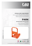
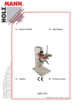
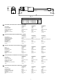
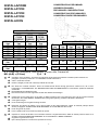
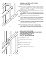
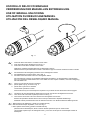
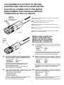
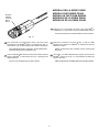
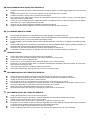
Tau
S.r.l. – Via E.Fermi, 43 Sandrigo (VI) Italia – TEL.+39444750190 FAX+39444750376 E- mail:[email protected]
AUTOMAZIONI PER CANCELLO A BATTENTE
AUTOMATISIERUNG VON FLÜGELTOREN
AUTOMATIONS FOR GATES
AUTOMATISATIONS POUR PORTAIL A BATTANT
SISTEMA DE AUTOMATIZACION PARA VERJAS CON BATIENTES
Serie P200, P200B, e P200BENC
Serie P200, P200B, und P200BENC
P200, P200B and P200BENC
Série P200, P200B et P200BENC
Serie P200, P200B y P200BENC
P225 / P225B / P225BENC
P250 / P250B / P250BENC
P270 / P270B / P270BENC
MANUALE USO E MANUTENZIONE
BEDIENUNGS - UND WARTUNGSANLEITUNG
USE AND MAINTENANCE MANUAL
MANUEL D'EMPLOI ET D'ENTRETIEN
MANUAL DE USO Y MANTENIMIENTO
I
La Casa costruttrice si riserva il diritto di apportare modifiche o miglioramenti al prodotto senza alcun preavviso.
Eventuali imprecisioni o errori riscontrabili nella presente edizione, saranno corretti nella prossima edizione.
All'apertura dell'imballo verificare che il prodotto sia integro. Non lasciare giocare i bambini dove si prospettino
pericoli di soffocamento.
Riciclare i materiali secondo la normativa vigente.
D
Die Herstellerfirma behält sich das Recht vor, Änderungen oder Verbesserungen des Produktes ohne
irgendeine Vorankündigung vorzunehmen.
Eventuelle in diesem Handbuch feststellbare Ungenauigkeiten oder Fehler werden in der nächsten Ausgabe
berichtigt werden.
Überprüfen Sie beim Öffnen der Verpackung, ob das Produkt unversehrt ist. Lassen Sie Kinder nicht dort spielen,
o Erstickungsgefahren möglich sind.
Recyclen Sie das Material gemäß der gültigen Vorschriften.
GB
The manufacturer reserves the right to modify or improve them without prior notice.
Any inaccuracies or errors found in this manual will be corrected in the next edition.
When opening the packing please check that the product is in excellent condition.
Do not let children play anywhere there may be a suffocation hazard.
Please recycle materials in compliance with current regulations.
F
Le Constructeur se réserve le droit d'apporter des modifications ou des améliorations au produit
sans aucun préavis.
Les éventuelles imprécisions ou erreurs trouvées dans cette édition seront corrigées dans la prochaine édition.
A l'ouverture de l'emballage, vérifier que le produit est intact. Ne pas laisser les enfants jouer avec les parties de
l'emballage pouvant présenter un risque d'étouffement.
Recycler les matériaux selon la réglementation en vigueur.
E
La empresa fabricante se reserva el derecho a aportar modificaciones o mejoras en el producto sin aviso previo.
Posibles errores o imprecisiones que se detecten en este manual se corregirán en el próximo.
Cuando abra el embalaje, compruebe la integridad del producto. No deje que los niños jueguen en zonas donde
exista peligro de ahogarse. Reciclar los materiales según las normativas vigentes
2
Fig. 1
A
P225 - P225B - P225BENC
P250 - P250B - P250BENC
P270 - P270B - P270BENC
I
CARATTERISTICHE TECNICHE DELLA SERIE P200
Alimentazione
Frequenza
Corrente assorbita
Potenza assorbita
Velocità motore
Lunghezza max anta
Corsa utile
Temperatura di esercizio
Intervento termoprotezione
Peso
Spinta assiale
D
P270
230 ac
50/60 Hz
1.4 A
300 W
900 giri/min
5.0 m
50 cm
-20°C ÷ 60°C
138°C
10.4 Kg
220 Kg
P225
230 Wechselstrom
50/60 Hz
1.4 A
300 W
900 Umdrehungen/min.
2.0 m
32 cm
-20°C ÷ 60°C
138° C
7,8 Kg
220 Kg
P250
230 Wechselstrom
50/60 Hz
1.4 A
300 W
900 Umdrehungen/min.
4.0 m
40 cm
-20°C ÷ 60°C
138° C
8,1 Kg
220 Kg
P270
230 Wechselstrom
50/60 Hz
1.4 A
300W
900Umdrehungen/min.
5.0 m
50 cm
20°C ÷ 60°C
138°C
10.4 Kg
220 Kg
P225
230 Vac
50-60 Hz
1.4 A
300 W
900 rpm
2.0 m
32 cm
-20°C to 60°C
138°C
7.8 kg
220 Kg
P250
230 Vac
50-60 Hz
1.4 A
300 W
900 rpm
4.0 m
40 cm
-20°C to 60°C
138°C
8.1 kg
220 Kg
P270
230 Vac
50-60 Hz
1.4 A
300 W
900 rpm
5.0 m
50 cm
-20°C to 60°C
138°C
10.4 kg
220 Kg
P250
230 V c.a
50/60 Hz
1.4 A
300 W
900 tours/mn
4,0 m
40 cm
-20°C ÷ 60°C
138°C
8,1 kg
220 Kg
P270
230 V c.a
50/60 Hz
1.4 A
300 W
900 tours/mn
5,0 m
50 cm
-20°C ÷ 60°C
138°C
10,4 kg
220 Kg
P250
230 ca
50/60 Hz
1.4 A
300 W
900 r.p.m
4.0 m
40 cm
-20°C ÷ 60°C
138°C
8.1 kg
220 Kg
P270
230 ca
50/60 Hz
1.4 A
300 W
900 r.p.m.
5.0 m
50 cm
-20°C ÷ 60°C
138°C
10.4 kg
220 Kg
* These technical datas are simply indicative.
CARACTERISTIQUES TECHNIQUES DE LA SERIE P200
Alimentation
Fréquence
Courant absorbé
Puissance absorbée
Vitesse moteur
Longueur max. battant
Course utile
Température de fonctionnement
Intervention protection thermique
Poids
Poussée axiale.
E
P250
230 ac
50/60 Hz
1.4 A
300 W
900 giri/min
4.0 m
40 cm
-20°C ÷ 60°C
138°C
8.1 Kg
220 Kg
* Diese technischen Daten dienen nur als Hinweis
TECHNICAL FEATURES OF THE P200 SERIES
Power
Frequency
Absorbed current
Absorbed power
Motor speed
Max gate length
Useful travel
Operating temperature
Thermal protection trips at
Weight
Axial thrust
F
P225
230 ac
50/60 Hz
1.4 A
300 W
900 giri/min
2.0 m
32 cm
-20°C ÷ 60°C
138° C
7.8 Kg
220 Kg
* Questi dati sono puramente indicativi
TECHNISCHE EIGENSCHAFTEN DER SERIE P200
Stromspeisung
Frequenz
Aufgenommener Strom
Aufgenommene Leistung
Motorgeschwindigkeit
Max. Flügellänge
Arbeitshub
Betriebstemperatur
Eingreifen des Wärmeschutzes
Gewicht
Längsschub
GB
788
940
1030
P225
230 V c.a
50/60 Hz
1.4 A
300 W
900 tours/mn
2,0 m
32 cm
-20°C ÷ 60°C
138°C
7,8 kg
220 Kg
* Ces données techniques sont purement indicatives
CARACTERISTIQUES TECHNIQUES DE LA SERIE P200
Alimentación
Frecuencia
Corriente absorbida
Potencia absorbida
Velocidad motor
Longitud máx. hoja puerta
Carrera útil
Temperatura de ejercicio
Activación termoprotección
Peso
Empuje axial.
P225
230 ca
50/60 Hz
1.4 A
300 W
900 r.p.m.
2.0 m
32 cm
-20°C ÷ 60°C
138°C
7.8 kg
220 Kg
* Estos datos son únicamente indicativos
3
Fig. 2
A
P225 - P225B - P225BENC
P250 - P250B - P250BENC
P270 - P270B - P270BENC
I
CARATTERISTICHE TECNICHE DELLA SERIE P200B, P 200BENC
Alimentazione
Corrente nominale
Potenza nominale
Velocità nominale motore
Lunghezza max anta
Corsa utile
Temperatura di esercizio
Peso
D
E
P250B/BENC
12 Vdc
1,6 A
60 W
1200/1470 giri/min
4.0 m
40 cm
-20°C + 60° C
8.1 Kg
P270B/BENC
12 Vdc
1,6 A
60 W
1200/1470 giri/min
5.0 m
50 cm
-20°C ÷ 60°C
10.4 Kg
P225B/BENC
P250B/BENC
12 Gleichstrom
12 Gleichstrom
1,6 A
1,6 A
60 W
60 W
1200/1470 Umdrehungen/min. 1200/1470 Umdrehungen/min.
P270B/BENC
12 Gleichstrom
1,6 A
60w
1200/1470 Umdrehungen/min.
2.0 m
32 cm
-20°C ÷ 60°C
7,8 Kg
4.0 m
40 cm
-20°C ÷ 60°C
8,1 Kg
5.0 m
50 cm
20°C ÷ 60°C
10,4 Kg.
P250B/BENC
12 Vdc
1,6 A
60 W
1200/1470 rpm
4.0 m
40 cm
-20°C to 60°C
8.1 kg
P270B/BENC
12 Vdc
1,6 A
60 W
1200/1470 rpm
5.0 m
50 cm
-20°C to 60°C
10.4 kg
TECHNICAL FEATURES OF THE P200B AND P 200BENC SERIES
Power
Rated current
Nominal power
Nominal motor speed
Max gate length
Useful travel
Operating temperature
Weight
F
P225B/BENC
12 Vdc
1,6 A
60 W
1200/1470 giri/min
2.0 m
32 cm
-20°C ÷ 60°C
7.8 Kg
TECHNISCHE EIGENSCHAFTEN DER SERIE P200B, P 200BENC
Stromspeisung
Aufgenommener Strom
Aufgenommene Leistung
Motorgeschwindigkeit
Umdrehungen/min.
Max. Flügellänge
Arbeitshub
Betriebstemperatur
Gewicht
GB
788
940
1030
P225B/BENC
12 Vdc
1,6 A
60 W
1200/1470 rpm
2.0 m
32 cm
-20°C to 60°C
7.8 kg
CARACTERISTIQUES TECHNIQUES DE LA SERIE P200B, P 200BENC
Alimentation
Courant nominal
Puissance nominale
Vitesse nominale moteur
Longueur max. battant
Course utile
Température de fonctionnement
P225B/BENC
12 V c.c.
1,6 A
60 W
1200/1470 tours/mn
2,0 m
32 cm
-20°C ÷ 60°C
Poids
7,8 kg
P250B/BENC
12 V c.c.
1,6 A
60 W
1200/1470 tours/mn
4,0 m
40 cm
-20°C ÷ 60°C
P270B/BENC
12 V c.c.
1,6 A
60 W
1200/1470 tours/mn
5,0 m
50 cm
-20°C ÷ 60°C
8,1 kg
10,4 kg
P250B/BENC
12 Vdc
1,6 A
60 W
1200/1470 r.p.m.
4.0 m
40 cm
-20°C ÷ 60°C
8.1 kg
P270B/BENC
12 Vdc
1,6 A
60 W
1200/1470 r.p.m.
5.0 m
50 cm
-20°C ÷ 60°C
10.4 kg
CARACTERISTICAS TECNICAS DE LA SERIE P200B Y P 200BENC
Alimentación
Corriente nominal
Potencia nominal
Velocidad nominal motor@
Longitud máx. hoja puerta
Carrera útil
Temperatura de ejercicio
Peso
P225B/BENC
12 Vdc
1,6 A
60 W
1200/1470 r.p.m.
2.0 m
32 cm
-20°C ÷ 60°C
7.8 kg
4
MATERIALI PER L'INSTALLAZIONE
INSTALLATIONSMATERIALIEN
INSTALLATION MATERIAL
MATERIAUX POUR L'INSTALLATION
MATERIALES PARA LA INSTALACIÓN
2
1
2
3
Fig. 3
5
4
6
I
1) Art.P-2250SP190
2) Art.M-V400008035
3) Art.-4) Art.P-2250SG190
5) Art.P-700PA1
6) Art.M-V300000125
: staffa piccola zincata
: vite zincata M8 x 35
: attuatore serie P200, P200B o P200BENC
: staffa grande zincata
: staffa angolare zincata
: condensatore cilindrico 12.5 µF ( solo per la serie P200 )
D
1) Art. P-2250SP190
2) Art. M-V400008035
3) Art.
4) Art. P-2250SG190
5) Art. P-700PA1
6) Art. M-V300000125
: kleiner verzinkter Befestigungsbügel
: verzinkte Schraube M8 x 35
: Kolbentorantrieb Serie P200, P200B oder P200B
: großer verzinkter Befestigungsbügel
: verzinkter Befestigungswinkel
: Zylindrischer Kondensator 12,5 µF (nur für die Serie P200)
GB 1) Art. P-2250SP190
2) Art. M-V400008035
3) Art. -4) Art. P-2250SG190
5) Art. P-700PA1
6) Art. M-V300000125
: Small galvanized bracket
: M8 x 35 galvanized screw
: P200, P200B or P200BENC series actuator
: Large galvanized bracket
: Angular galvanized bracket
: 12.5 µF cylindrical capacitor
F
1)Art. P-2250SP190
2) Art. M-V4500008035
3) Art.
4) Art. P-2250SG190
5) Art. P-700PA1
6) Art. M-V300000125
: Petite patte de fixation zinguée
: Vis M8 x 35 zinguée
: Actionneur série P200, P200B ou P200BENC
: Grande patte de fixation zinguée
: Patte angulaire de fixation zinguée
: Condensateur cylindrique 12,5 µF (seulement pour la série P200)
E
1) Art. P-225OSP190
2) Art. M-V400008035
3) Art.
4) Art. P-2250SG190
5) Art. P-700PA1
6) Art. M-V300000125
: brida pequeña galvanizada
: tornillo galvanizado M8 x 35
: accionador serie P200, P200B o P200BENC
: brida grande galvanizada
: brida angular galvanizada
: condensador cilíndrico 12.5 µF (sólo para la serie P200)
5
CONSIDERAZIONI PRELIMINARI
INSTALLAZIONE
INSTALLATION
INSTALLATION
INSTALLATION
INSTALACION
VORÜBERLEGUNGEN
PRELIMINARY CONSIDERATIONS
CONSIDERATIONS PRELIMINAIRES
CONSIDERACIONES PRELIMINARES
Y° = 90°
A(mm)
max
70
80
100
120
140
160
P225
P250
P270
P225B
P250B
P270B
P225BENC P250BENC P270BENC
B(mm)
B(mm)
B(mm)
max
max
max
190
290
410
180
280
400
160
260
380
140
240
360
120
220
340
100
200
320
Fig. 4
Y° > 90°
D (mm) A(mm) B(mm)
max
max
max
200x200
90
160
100
160
300x300
70
210
80
210
C(mm)
max
280
380
500
400x400
D(mm)
max
140 x 140
200 x 200
250 x 250
>400
100
260
Y°
TIPO
max
KIND
>100° P225/B/BENC
>100°
95°
95°
>97° P250/B/BENC
P270/B/BENC
C = Corsa utile, Arbeitshub, Useful travel, Course utile, Carrera útil.
NB: (A+B) < (C-2cm)
A _˜ B
I
D
GB
F
E
fi
fifi
fi
fifi
fi
fifi
fi
fifi
fi
fifi
rispettare i valori di tabella . Se si deve far riferimento ad angoli diversi utilizzare il metodo pratico descritto nel
paragrafo "operazioni preliminari" di "FISSAGGIO STAFFA PICCOLA".
oliare i cardini del cancello.
fissare la flangia piccola sulla struttura portante del cancello.
Die Werte der Tabelle einhalten. Wenn auf abweichende Winkel bezug genommen werden muß, die in dem
Paragraphen "VORARBEITEN" der "BEFESTIGUNG DES KLEINEN BÜGELS" beschriebene praktische Methode
verwenden.
Die Stützzapfen des Gittertores ölen.
Den kleinen Flansch an der tragenden Struktur des Gittertores befestigen.
please keep to the values given in the table. If different angles have to be referred to then use the practical method
described in the “PRELIMINARY OPERATIONS” paragraph regarding “FIXING THE SMALL BRACKET”.
oil the gate’s hinges.
fix the small flange to the gate’s bearing structure.
Respecter les valeurs du tableau. Si on doit se référer à des angles différents, utiliser la méthode pratique décrite
dans le paragraphe "OPERATIONS PRELIMINAIRES" de "FIXATION PETITE PATTE"
Huiler les gonds du portail.
Fixer la petite bride sur la structure portante du portail.
respetar los valores de la tabla. Si es necesario referirse a ángulos diferentes, utilizar el método práctico citado en el
apartado "OPERACIONES PRELIMINARES" de "FIJACION DE LA BRIDA PEQUEÑA".
engrasar los goznes de la verja.
fijar la brida pequeña en la estructura portante de la verja.
6
SPINTA ASSIALE
LÄNGSSCHUB
AXIAL THRUST
POUSSÉE AXIALE
EMPUJE AXIAL
FN = F * SIN (Y°)
T _˜ FN * D ➞ T _˜ F * D * SIN (Y°)
F= Spinta assiale, Längsschub, Axial thrust, Poussée axiale, Empuje axial
T= coppia che movimenta l’ anta, trascurando tutti gli attriti che si sviluppano sui cardini dell’ anta stessa.
T= Kräftepaar, das den Flügel bewegt, wobei keine der Reibungen, die sich an den Torflügelzapfen entwickeln, beachtet wird.
T= torque that moves the wing, neglecting all friction created on the wing’s hinges.
T=couple assurant la manoeuvre du battant en négligeant tous les frottements qui se créent sur les gonds du battant.
T= par que mueve la hoja, pasando por alto todas las fricciones que se producen en los quicios de la hoja
7
SE IL PILASTRO E' IN MURATURA ... / WENN DER PFEILER GEMAUERT IST ...
IF THE PILLAR IS MADE OF BRICK ... / SI LE PILIER EST EN MAÇONNERIE...
SI EL PILAR ES DE CEMENTO...
Piastra angolare
Winkelplatte
angle plate
plaque angulaire
placa angular
Fig. 5
Fig. 6
I
- usare 4 tasselli ad espansione M10 per attaccare la piastra angolare al muro
- fissare la staffa grande alla piastra angolare scegliendo fra le alternative di Fig. 6 usando due bulloni M8
D
- die 4 Expansionsdübel M10 verwenden, um die Winkelplatte an der Mauer zu befestigen;
- den großen Befestigungsbügel an der Winkelplatte befestigen, indem zwi schen den Alternativen in Abb. 6 gewählt und
die beiden Mutterschrauben M8 verwendet werden.
GB
- use 4 M10 expansion bolts to fix the angle plate to the wall
- fix the large bracket to the angle plate, selecting from the alternatives given in Fig. 6 and using two M8 bolts.
F
- Utiliser 4 chevilles à expansion M10 pour fixer la plaque angulaire au mur.
- Fixer la grande patte de fixation à la plaque angulaire avec deux boulons M8 en choisissant entre les solutions proposées
par la fig. 6
E
- emplear 4 tornillos de expansión M10 para sujetar la placa angular en el muro
- fijar la brida grande en la placa angular según las alternativas indicadas en la Fig. 6 mediante dos pernos M8
8
SE IL PILASTRO E' METALLICO / WENN DER PFEILER AUS METALL IST
IF IT IS A METAL PILLAR / SI LE PILIER EST EN METAL
SI EL PILAR ES DE METAL
Staffa grande
Großer Befestigungsbügel
large bracket
grande patte de fixation
brida grande
Fig. 7
I
Saldare accuratamente la staffa grande al cancello
D
Den großen Befestigungsbügel sorgfältig am Tor anschweißen.
GB
Weld the large bracket accurately to the gate.
F
Souder soigneusement la grande patte de fixation au portail
E
Soldar perfectamente la brida grande en la verja
9
FISSAGGIO STAFFA PICCOLA
BEFESTIGUNG DES KLEINEN BÜGELS
FIXING THE SMALL BRACKET
FIXATION PETITE PATTE
FIJACION DE LA BRIDA PEQUEÑA
OPERAZIONI PRELIMINARI
VORARBEITEN
PRELIMINARY OPERATIONS
OPERATIONS PRELIMINAIRES
OPERACIONES PRELIMINARES
Fig. 8
I
1. ancorare l'attuatore alla staffa grande usando con la vite in dotazione ( vedi Fig. 8 )
2. svitare il braccio dell'attuatore fino alla sua quasi completa estensione ( lasciare un giro avvitato )
3. avvitare la staffa piccola al braccio dell'attuatore tramite la vite di dotazione(similmente a quanto descritto in Fig. 10) e
posare la staffa piccola all'anta del cancello completamente chiuso per determinare dove sarà saldata
Prima di passare alla fase successiva eseguire la seguente prova:
1. aprire manualmente il cancello fino all'angolo massimo voluto
2. attivare lo sblocco manuale ( vedi paragrafo apposito )
3. avvitare il braccio fino a che la staffa piccola possa sovrapporsi alla posizione appena marcata sull'anta
Se l'operazione è possibile l'installazione è corretta.
Questo metodo si può usare per stabilire dove saldare la staffa piccola per ogni angolo di apertura ( X° ) voluto a
condizione che ciò sia possibile ( parametri A e B e corsa utile dell'attuatore permettendo )
10
D
1. Den Kolbentorantrieb an dem großen Bügel verankern; dazu die sich in der Ausstattung befindliche Schraube verwen
den (siehe Abb. 8).
2. Den Arm des Kolbentorantriebs losschrauben, bis er fast seine vollständige Ausdehnung erreicht hat (eine Umdrehung
angeschraubt lassen).
3. Den kleinen Befestigungsbügel am Arm des Kolbentorantriebs mit Hilfe der sich in der Ausstattung befindlichen
Schraube anschrauben (ähnlich dem, wie in Abb. 10 beschrieben) und den kleinen Befestigungsbügel an den Flügel des
vollständig geschlossenen Gittertores anlegen, um zu bestimmen, wo er angeschweißt werden soll.
Bevor zu der nachfolgenden Arbeitsphase übergegangen wird, sollte der folgende Versuch durchgeführt werden:
1. Das Gittertor von Hand bis zum maximal gewünschten Winkel öffnen.
2. Die manuelle Entriegelung aktivieren (siehe entsprechender Paragraph).
3. Den Arm anschrauben, bis daß sich der kleine Befestigungsbügel über der soeben auf dem Flügel markierten
Position befindet.
Ist dieser Vorgang möglich, ist die Installation korrekt.
Diese Methode kann auch verwendet werden, um festzulegen, wo der kleine Befestigungsbügel für den jeweils
gewünschten Öffnungswinkel (X°) angeschweißt werden soll; Bedingung ist jedoch, daß dies möglich ist (Parameter A und
B und Arbeitshub des Kolbentorantriebs müssen dies erlauben).
GB
1. anchor the actuator to the large bracket using the screw provided (see Fig. 8)
2. unscrew the actuator arm until it is nearly completely out (leave one turn of the screw)
3. tighten the small bracket to the actuator arm using the screw provided (similar to the description in Fig. 10) and rest the
small bracket against the gate when it is completely shut to see where it has to be welded.
Before going on to the next phase please carry out the following test:
1. manually open the gate to the maximum required angle
2. activate the manual unlock (see relative paragraph)
3. tighten the arm until the small bracket finds itself over the position just marked on the gate.
If the small bracket does cover the position marked it means installation has been done correctly.
This method can be used to establish where the small bracket will have to be welded for each opening angle (X°)
requiredprovided it is possible (parameters A and B and the actuator’s useful travel permitting).
F
1. Fixer l'actionneur à la grande patte en utilisant la vis fournie (voir Fig. 8)
2. Dévisser le bras de l'actionneur jusqu'à son extension presque complète (laisser un tour vissé).
3. Visser la petite patte au bras de l'actionneur avec la vis fournie (comme le décrit la Fig.10) et poser la petite patte sur le
battant du portail complètement fermé pour calculer où elle devra être soudée.
Avant de passer à la phase successive, effectuer l'essai suivant:
1. Ouvrir manuellement le portail jusqu'à l'angle maximum voulu.
2. Activer le déblocage manuel (voir paragraphe spécifique).
3. Visser le bras jusqu'à ce que la petite patte puisse se superposer à la position marquée sur le battant.
Si l'opération est possible, l'installation est correcte.
On peut utiliser cette méthode pour calculer où souder la petite patte pour chaque angle d'ouverture (X°) désiré à
condition que cela soit possible (si les paramètres A et B et la course utile de l'actionneur le permettent).
E
1. sujetar el accionador a la brida grande mediante el tornillo en equipamiento (ver la Fig. 8 )
2. desatornillar el brazo del accionador hasta que se extienda casi del todo (dejarlo atornillado con un giro)
3. Atornillar la brida pequeña al brazo del accionador con el tornillo en equipamiento (como se describe en la Fig.10) y colo
car la brida pequeña en la verja, que debe estar completamente cerrada, a fin de determinar dónde se soldará
Antes de pasar a la fase sucesiva, hay que comprobar lo siguiente:
1. abrir manualmente la verja hasta el máx. ángulo deseado
2. activar el bloqueo manual (ver el apartado relativo)
3. atornillar el brazo hasta que la brida pequeña se pueda superponer a la posición que se acaba de marcar en la verja
Si esta operación se puede realizar, significa que la instalación es correcta.
Es posible llevar a cabo este método a fin de establecer dónde hay que soldar la brida pequeña por cada ángulo de
abertura (X°) deseado, siempre y cuando sea posible (o sea, con los parámetros A y B y la carrera útil del accionador justos)
11
FISSAGGIO / BEFESTIGUNG / FIXING
FIXATION / FIJACION
I
saldare accuratamente la staffa all'anta del cancello nella posizione prestabilita
per aiutarsi in questa operazione è possibile lasciare la staffa piccola
avvitata al braccio dell'attuatore come dal punto 3 del paragrafo precedente
per posarla sull'anta nella posizione prestabilita.
D
Den Befestigungsbügel sorgfältig am Flügel des Gittertors in der zuvor festge
legten Position anschweißen.
Um diese Arbeit zu erleichtern, kann der kleine Befestigungsbügel am Arm
des Kolbentorantriebs wie unter Punkt 3 des vorhergehenden Paragraphs
angeschraubt bleiben, um ihn in der zuvor festgelegten Position auf den Flügel
zu setzen.
GB
weld the bracket accurately to the gate in the established position.
to help yourself do the job properly you can leave the small bracket
screwed to the actuator arm, as mentioned in point 3 of the previous
paragraph, so it can be placed against the gate in the established position.
F
Souder soigneusement la patte au battant du portail dans la position préétablie.
pour s'aider dans cette opération, il est possible de laisser la petite patte
vissée au bras de l'actionneur comme au point 3 du paragraphe précédent
pour la poser sur le battant dans la position préétablie.
E
soldar con mucho cuidado la brida en la verja, en la posición prefijada
para que esta operación resulte más fácil, es posible dejar la brida
pequeña atornillada en el brazo del accionador, como figura en el punto 3 del
apartado precedente, para apoyarla en la verja, en la posición prefijada.
Fig. 9
ANCORAGGIO ATTUATORE
VERANKERUNG DES KOLBENTORANTRIEBS
ANCHORING THE ACTUATOR
ANCRAGE ACTIONNEUR
ANCLAJE DEL ACCIONADOR
I
avvitare la vite come in Fig. 10
D
Die Schraube wie in Abb. 10 anschrauben.
GB
tighten the screw as shown in Fig. 10
F
Visser la vis comme sur la Fig. 10
E
Apretar los tornillos según se indica en la Fig. 10
Fig. 10
12
USO DELLO SBLOCCO MANUALE
VERWENDUNG DER MANUELLEN ENTRIEGELUNG
USE OF MANUAL UNLOCKING
UTILISATION DU DEBLOCAGE MANUEL
UTILIZACIÓN DEL DESBLOQUEO MANUAL
Fig. 11
I
1.
2.
3.
inserire la chiave nello sblocco e ruotarla in senso orario
tirare verso l'alto il tappo di plastica come da Fig. 11
tirare la leva verso l'alto e ruotarla in senso orario
effettuare le operazioni descritte all'inverso per disinserire lo sblocco
riabbassare la leva precedentemente ruotata e richiudere il tappo se si decide di lasciare lo sblocco attivato
D
1.
2.
3.
Den Schlüssel in die Entriegelung einsetzen und im Uhrzeigersinn drehen.
Den Plastikstopfen nach oben ziehen, wie in Abb. 11
Den Hebel nach oben ziehen und ihn im Uhrzeigersinn drehen.
Die beschriebenen Vorgänge in umgekehrter Reihenfolge durchführen, um die Entriegelung auszuschalten.
Den zuvor gedrehten Hebel wieder nach unten stellen und den Stopfen schließen, wenn die Entriegelung
akti viert bleiben soll.
GB
1.
2.
3.
put the key into the lock and turn it clockwise
pull the plastic cap up, as shown in Fig. 11
pull the lever up and turn it clockwise
reverse these operations to relock
lower the lever that you turned and put the cap back on if you decide to leave the unlock function engaged.
F
1.
2.
3.
Introduire la clé dans le dispositif de déblocage et la tourner dans le sens des aiguilles d'une montre.
Tirer vers le haut le bouchon en plastique comme sur la Fig. 11
Tirer le levier vers le haut et le tourner dans le sens des aiguilles d'une montre.
Effectuer les opérations décrites dans le sens inverse pour désactiver le dispositif de déblocage.
Rabaisser le levier précédemment tourné et refermer le bouchon si on décide de laisser le déblocage activé.
E
1. Meter la llave en el desbloqueo y girarla en el sentido del reloj
2. tirar hacia arriba el tapón de plástico, como en la Fig.11
3. tirar la palanca hacia arriba y girarla en el sentido del reloj
para desconectar el desbloqueo, llevar a cabo las citadas operaciones pero en orden inverso
volver a bajar la palanca que se había girado antes, y cerrar otra vez el tapón si se desea dejar activado el
desbloqueo
13
COLLEGAMENTO ELETTRICO AL MOTORE
ELEKTRISCHER ANSCHLUß AN DEN MOTOR
ELECTRICAL CONNECTION TO THE MOTOR
BRANCHEMENT ELECTRIQUE AU MOTEUR
CONEXION ELECTRICA AL MOTOR
Coperchio
Plastikdeckel
plastic cover
couvercle plastique
tapa de plástico
I
rimuovere le 4 viti di fissaggio e sollevare il coperchio plastico come in Fig 12
D
Die 4 Befestigungsschrauben entfernen und den
Plastikdeckel anheben wie in Abb. 12
remove the 4 securing screws and lift the plastic cover as
shown in Fig. 12
GB
F
Enlever les 4 vis de fixation et soulever le couvercle plastique
comme sur la Fig. 12
E
extraer los 4 tornillos de fijación y levantar la tapa de plástico, como se indica en la Fig.12
Fig. 12
MODELLI DELLA SERIE P200
MODELLE DER SERIE P200
MODELS IN THE P200 SERIES
MODELES DE LA SERIE P200
MODELOS DE LA SERIE P200
Morsetto
Klemme
Terminal
Borne
Borne
I
1. collegarsi al morsetto di Fig. 13 con cavi di sezione almeno
pari a 1.5 mm2 provando il verso di rotazione del motore e
ricordando che:
cavo giallo-verde : massa
cavo blu
: comune
cavo nero
: fase
cavo marrone
: fase
2. in prossimità della scheda elettronica di comando, collegare
il condensatore in dotazione in parallelo alle 2 fasi del motore
Usare esclusivamente centraline dotate di frizione elettrica
Fig. 13
D
1. Den Anschluß an die Klemme, Abb. 13, mit Kabeln durchführen,
die einen Durchmesser von mindesten 1,5 mm2 aufweisen, die
Drehrichtung des Motors überprüfen und folgendes beachten:
Gelb-grünes Kabel : Erde
Blaues Kabel
: Gemeinsame
Schwarzes Kabel
: Phase
Braunes Kabel
: Phase
2. In der Nähe der elektronischen Steuerkarte den sich in der
Ausstattung befindlichen Kondensator parallel an die 2
Phasen des Motors anschließen.
Ausschließlich Zentralen verwenden, die mit elektrischem
Drehmomentbegrenzer ausgestattet sind.
F
1. Effectuer la connexion à la borne de la Fig. 13 avec des
câbles d'une section d'au moins 1,5 mm2 en essayant le
sens de rotation du moteur et en se souvenant que:
câble jaune-vert
: masse
câble bleu
: commun
câble bleu
: commun
câble noir
: phase
câble marron
: phase
2. A proximité de la carte électronique de commande, connecter le
condensateur fourni en parallèle aux deux phases du moteur.
Utiliser exclusivement des centrales munies d'embrayage
électrique
GB
1. connect up to the terminal of Fig. 13 with a wire whose cross
section should at least be equal to 1.5 mm2, checking motor
rotation direction and remembering that:
the yellow-green wire is the earth wire
blue is the common wire
black is the phase wire
and brown is the phase wire.
2. connect the capacitor provided in parallel with the motor’s
two phases in proximity of the electronic control card.
Only use units equipped with an electric friction.
E
1. conectarse al borne de la Fig. 13 con cables que tengan una
sección de al menos 1.5 mm2, comprobando el sentido de
rotación del motor, recordando que:
cable amarillo-verde
: tierra
cable azul
: común
cable negro
: fase
cable marrón
: fase
2. cerca de la placa electrónica, conectar el condensador en
equipamiento, en paralelo a las 2 fases del motor
Utilizar exclusivamente centralitas dotadas de embrague eléctrico
14
MODELLI DELLA SERIE P200B
MODELLE DER SERIE P200B
MODELS IN THE P200B SERIES
MODELES DE LA SERIE P200B
MODELOS DE LA SERIE P200B
Morsetto
Klemme
Terminal
Borne
Borne
I
collegarsi con cavo bipolare di sezione pari a 2.5 mm2 al
morsetto di Fig. 14 provando il verso di rotazione del motore
Usare esclusivamente centraline dotate di frizione elettrica
Fig. 14
D
Den Anschluß mit zweipoligem Kabel, das über einen
Durchmesser von 2,5 mm2 verfügt, an der Klemme, Abb. 14,
durchführen und die Drehrichtung des Motors überprüfen.
F
Ausschließlich Zentralen verwenden, die mit elektrischem
Drehmomenbegrenzer ausgestattet sind.
GB
Effectuer la connexion à la borne de Fig. 14 avec un câble
bipolaire d'une section de 2,5 mm2 en essayant le sens de
rotation du moteur.
Utiliser exclusivement des centrales munies d'embrayage
électrique
connect a bipolar cable where the wire’s cross section must be
equal to 2.5 mm2 to the terminal of Fig.14, checking motor
rotation direction.
E
Only use units equipped with an electric friction.
conectarse con cables bipolares que tengan una sección de
2.5 mm2 al borne de la Fig. 14 Comprobando el sentido de
rotación del motor
Utilizar exclusivamente centralitas dotadas de embrague eléctrico.
15
MODELLI DELLA SERIE P200BENC
MODELLE DER SERIE P200BENC
MODELS IN THE P200BENC
MODELES DE LA SERIE P200BENC
MODELOS DE LA SERIE P200BENC
Fig. B
Fig. A
I
Estrarre la morsettiera mamut dalla propria sede, come indicato in figura A e prestare attenzione a come sono collegati i fili
nell’ordine, figura B:
Fili della scheda encoder fotodiodo: bianco, marrone, bleu (sez 0,5 mm2);
Fili fase motore: nero, rosso (sez 2,5 mm2);
I fili di segnale dell’encoder vanno collegati ai connettori della scheda MEC20 in questo modo: marrone - morsetto 21, bleu morsetto 22, bianco 1°motore - morsetto 23, bianco 2° motore - morsetto 24.
Collegare i fili motore nero,rosso del 1° motore ai morsetti 7-8 e del 2° motore ai morsetti 9-10. Verificare che ad un imput di
apertura corrisponda la manovra desiderata; in caso contrarrio invertire la posizione dei fili nero-rosso.
Per i collegamenti alla scheda di comando usare tassativamente fili della stessa sezione.
D
Das Klemmenbrett Mamut wie in Abbildung A gezeigt aus seinem Sitz nehmen, dabei beachten, in welcher Reihenfolge die
Drähte angeschlossen sind, wie in Abbildung B:
Drähte der Encoder-Photodiodenkarte: weiß, braun, blau (Schnitt 0,5 mm2);
Drähte der Motorphase: schwarz, rot (Schnitt 2,5 mm2);
Die Signaldrähte des Encoders müssen an die Verbinder der Karte MEC20 wie folgt angeschlossen werden: braun Klemme 21, blau - Klemme 22, weiß 1. Motor - Klemme 23, weiß 2. Motor - Klemme 24.Die Motordrähte schwarz und rot
des 1. Motors an die Klemmen 7-8 und des 2. Motors an die Klemmen 9-10 anschließen. Überprüfen, dass nach einem Öffnungs-Imput das gewünschte Manöver ausgeführt wird; im gegenteiligen Fall die Position der Drähte schwarz-rot umkehren.Für die Anschlüsse an die Steuerkarte ausschließlich Drähte mit gleichem Schnitt verwenden.
GB
Pull the terminal board out of its housing, as shown in Fig. A and observe how the wires are connected in order as shown in
Fig. B:
Wires of the photodiode encoder card: white, brown, blue (0.5 mm2 cross section);
Motor phase wires: black, red ( 2.5 mm2 cross section);
The encoder’s signal wires are to be connected to the MEC20 card connectors in the following way: brown - terminal 21,
blue - terminal 22, white 1st motor - terminal 23, white 2nd motor - terminal 24.Connect the black and red wires of the 1st
motor to terminals 7 and 8 and to terminals 9 and 10 those of the 2nd motor. Check that the required manoeuvre corresponds to an opening input; to the contrary, reverse the position of the black-red wires.It is essential that the cross section of
the wires must be identical for connecting to the command card.
F
Extraire le bornier mamut de son logement comme l’indique la figure A et faire attention aux connexions des fils, à savoir,
comme l’indique la figure B:
Fils de la carte codeur photodiode: blanc, marron, bleu (section 0,5 mm2);
Fils phase moteur: noir, rouge (section 2,5 mm2);
Les fils du signal du codeur doivent être connectés aux connecteurs de la carte MEC20 de la manière suivante: marron borne 21, bleu - borne 22, blanc 1er moteur - borne 23, blanc 2e moteur - borne 24.Connecter les fils moteur noir-rouge du
1er moteur aux bornes 7-8 et du 2e moteur aux bornes 9-10. Vérifier qu’une impulsion d’ouverture provoque la manoeuvre
désirée; en cas contraire, inverser la position des fils noir-rouge.Pour les connexions à la carte de commande, utiliser absolument des fils de même section.
E
Extraiga el tablero de bornes Mamut de su alojamiento, como muestra la figura A y observe con atención el orden en el cual
están conectados los cables, como muestra la figura B:
Cables de la tarjeta encóder fotodiodo: blanco, marrón y azul (secc 0,5 mm2);
Cables de la fase del motor: negro y rojo (secc 2,5 mm2);
Los cables de señal del encóder se conectan a los conectores de la tarjeta MEC20 de la siguiente manera: marrón - borne
21, azul - borne 22, blanco 1er. motor - borne 23, blanco 2do. motor - borne 24.Conecte los cables negro y rojo del 1er.
motor a los bornes 7-8 y los del 2do. motor a los bornes 9-10. Controle que a un input de apertura corresponda la maniobra
deseada; en caso contrario invierta la posición de los cables negro y rojo.Para las conexiones a la tarjeta de comando, use
únicamente cables con la misma sección.
16
I
RACCOMANDAZIONI DI CARATTERE GENERALE
fi
fi
fi
fi
fi
fi
fi
D
GB
Integrare la sicurezza del cancello conformemente alla normativa vigente ( per l'Italia leggere appendice sulla norma UNI
8612 )
Scegliere percorsi brevi per i cavi e tenere separati i cavi di potenza dai cavi di comando
Installare la scheda comando entro una scatola a tenuta stagna
Per la messa a punto della coppia massima del motoriduttore, attenersi alle normative in vigore ( per l'Italia leggere
l'appendice sulla norma UNI 8612 )
In accordo con la normativa europea in materia di sicurezza si consiglia di inserire un interruttore esterno per poter togliere
l'alimentazione in caso di manutenzione del cancello
verificare che ogni singolo dispositivo installato sia efficiente ed efficace
affiggere cartelli facilmente leggibili che informino della presenza del cancello motorizzato
ALLGEMEINE EMPFEHLUNGEN
fi
fi
fi
fi
fi
fi
fi
Die Sicherheit des Gittertores in Übereinstimmung mit den gültigen Vorschriften integrieren
Es sollten kurzen Strecken für die Kabel gewählt und die Leistungskabel von den Steuerkabeln getrennt gehalten werden.
Die Steuerkarte muß in einem dichten Gehäuse installiert werden.
Für die Einstellung des maximalen Drehmomentes des Getriebemotors muß sich an die gültigen Vorschriften gehalten
werden.
In Übereinstimmung mit den europäischen Sicherheitsnormen wird die Installation eines externen Schalters empfohlen, um
die Stromzufuhr bei einer Wartung des Gittertores unterbrechen zu können.
Überprüfen, ob jede einzelne installierte Vorrichtung leistungsfähig und wirksam ist.
Leicht lesbare Schilder anbringen, die darüber informieren, daß ein motorisiertes Gittertor vorhanden ist.
GENERAL ADVICE
fi
fi
fi
fi
fi
fi
fi
Install a gate safety system that complies with current regulations
Choose short routes for cables and keep power cables separate from control ones.
Install the control card in a waterproof box.
Please refer to current regulations when setting the geared motor’s maximum torque
We advise you to install an outdoor switch, in compliance with European standards on the issue of safety, to turn the electricity off when servicing the gate.
Check that each single device installed is efficient and effective.
Affix easily readable signs, warning about the presence of a motorized gate.
F
RECOMMANDATIONS DE CARACTERE GENERAL
fi
fi
fi
fi
fi
fi
fi
E
Assurer la sécurité du portail conformément aux dispositions prescrites par les normes en vigueur
Choisir des parcours brefs pour les câbles et séparer les câbles de puissance des câbles de commande.
Installer la carte de commande dans un boîtier étanche.
Pour la mise au point du couple maximum du motoréducteur, suivre les normes en vigueur
Conformément à la norme européenne en matière de sécurité, il est conseillé d'insérer un interrupteur externe pour pouvoir couper l'alimentation en cas d'intervention de maintenance sur le portail.
Vérifier que tous les dispositifs installés fonctionnent correctement.
Placer des panonceaux bien lisibles qui informent de la présence du portail motorisé.
RECOMENDACIONES DE CARÁCTER GENERAL
fi
fi
fi
fi
fi
fi
fi
Integrar la seguridad de la verja con las normas vigentes
Elegir recorridos breves para los cables y mantener separados los cables de potencia de los de mando.
Instalar la ficha de mando dentro de una caja hermética.
Para la puesta a punto del par máximo motorreductor, respetar la normativa en vigor
De acuerdo con la normativa europea en materia de seguridad, se aconseja instalar un interruptor externo para poder sacar
la corriente cuando se deban realizar operaciones de mantenimiento de la verja.
Comprobar que cada uno de los dispositivos funcione y sea eficaz.
Colocar carteles de fácil lectura y comprensión que informen de la presencia de una verja motorizada.
17
I
USO
Gli attuatori P225 / P225B / P225BENC, P250 / P250B / P250BENC e P270 / P270B / P270BENC sono stati progettati per movimentare ante della lunghezza massima rispettiva di m. 2.5,4.0 e 5.0.
Si fa' espresso divieto di utilizzare l'apparecchio per scopi diversi o in circostanze diverse da quelle menzionate
Normalmente , la centralina elettronica installata (che deve avere la frizione elettrica incorporata)
consente di selezionare il funzionamento :
automatico
: un impulso di comando esegue l'apertura e la chiusura del cancello
semiautomatico
: un impulso di comando esegue l'apertura o la chiusura del cancello
In caso di mancanza di energia elettrica, Il cancello può funzionare ugualmente per i modelli (serie P200B ) alimentabili con batteria tampone ; per la gestione manuale agire prima sul dispositivo di sblocco manuale.
Si ricorda che siamo in presenza di un dispositivo automatico e alimentato a corrente, perciò da usare con precauzione.
In particolare , si ammonisce di:
●
non toccare l'apparecchio con mani bagnate e/o piedi bagnati o nudi
●
togliere la corrente prima di aprire la scatola comandi e/o l'attuatore
●
non tirare il cavo di alimentazione per staccare la presa di corrente
●
non toccare il motore se non siete sicuri che sia raffreddato
●
mettere in movimento il cancello solo quando è completamente visibile
●
tenersi fuori dal raggio di azione del cancello se questo è in movimento: aspettare fino a che non sia fermo
●
non lasciare che bambini o animali giochino in prossimità del cancello
●
non lasciare che bambini o incapaci usino il telecomando o altri dispositivi di azionamento
●
effettuare una manutenzione periodica
●
in caso di guasto , togliere l'alimentazione e gestire il cancello manualmente solo se possibile e sicuro. Astenetersi da ogni
intervento e chiamare un tecnico autorizzato.
D
GEBRAUCH
Die Kolbentorantriebe P225 / P225B / P225BENC, P250 / P250B / P250BENC und P270 / P270B / P270BENC wurden für
die Bewegung von Flügeltoren entwickelt, deren Flügel max. 2,5 Meter, 4,0 Meter oder 5,0 Meter betragen.
Es wird ausdrücklich verboten, die Vorrichtung für unterschiedliche Zwecke oder unter Umständen einzusetzen, die
von den genannten abweichen.
Normalerweise ermöglicht die installierte elektronische Steuerzentrale (die einen eingebauten elektrischen
Drehmomentbegren-zer haben muß) die Wahl der Funktion:
Automatisch
Halbautomatisch
: Ein Steuerimpuls führt das Öffnen und das Schließen des Gittertores durch.
: Ein Steuerimpuls führt das Öffnen oder das Schließen des Gittertores durch.
Bei fehlender Stromzufuhr kann das Gittertor trotzdem funktionieren, wenn es sich um Modelle (Serie P200B) handelt, die
mit Pufferbatterie gespeist werden können; für die manuelle Bedienung zuerst die
Entriegelungsvorrichtung betätigen.
Es wird daran erinnert, daß es sich um eine automatische Vorrichtung handelt, die mit Strom gespeist wird und daher
mit Vorsicht zu verwenden ist. Im besonderen wird vor folgendem gewarnt:
●
die Vorrichtung nicht mit feuchten Händen und/oder feuchten oder nackten Füßen berühren;
●
die Stromzufuhr unterbrechen, bevor das Steuergehäuse und/oder der Getriebemotor geöffnet werden;
●
nicht an dem Stromkabel ziehen, um die Stromzufuhr zu unterbrechen;
●
den Motor nicht berühren, wenn Sie sich nicht sicher sind, daß er abgekühlt ist;
●
das Gittertor nur in Bewegung setzen, wenn es vollständig sichtbar ist;
●
sich außerhalb des Aktionsradius des Gittertores aufhalten, wenn sich dieses in Bewegung befin det: warten Sie, bis es
stillsteht;
●
Kinder oder Tiere nicht in der Nähe des Gittertores spielen lassen;
●
Kinder oder unfähige Personen nicht die Fernsteuerung oder andere Vorrichtungen für die Betätigung verwenden lassen;
●
eine periodische Wartung durchführen;
●
im Falle einer Störung die Stromzufuhr unterbrechen und das Gittertor nur dann manuell betätigen, wenn dies möglich
und sicher ist. Keine Eingriffe durchführen und einen autorisierten Techniker rufen.
GB
USE
Actuators P225 / P225B / P225BENC, P250 / P250B / P250BENC and P270 / 270B / P270BENC are designed to move
gates with a maximum length of, respectively, 2.5, 4.0 and 5.0 metres.
It is absolutely forbidden to use the device for any other purposes or under circumstances different from those mentioned.
The electronic unit installed (which must have a built-in electric friction) normally permits you to select the following functions:
automatic
: a command pulse will open and shut the gate
semi-automatic
: a command pulse will open or shut the gate
If there is a blackout the gate will still work for the models (P200B series) that can be powered by a buffer
battery; to manually operate the gates you first have to act on the unlock device.
18
Remember that this is an automatic device which is powered by electricity, consequently use with care. In particular,
remember:
●
never touch the device with wet hands and/or wet or bare feet
●
turn the electricity off prior to opening the command box and/or actuator
●
do not pull the lead to pull the plug out
●
do not touch the motor unless you are certain it is cold
●
put the gate in movement only when it is completely visible
●
keep out of the gate’s range of action if it is moving: wait until it has stopped
●
do not let children or animals play near the gate
●
do not let children, or incapable people, use the remote control or other operating devices
●
carry out routine maintenance
●
in the case of a failure, turn the electricity off and work the gate manually only if it is possible and safe.
Refrain from touching the gate and call an authorised technician.
F
EMPLOI
Les actionneurs P225 / P225B / P225BENC, P250 / P250B / P250BENC et P270 / P270B / P270BENC ont été projetés pour
ouvrir et fermer des portails avec battant maximum respectif de 2,5, 4,0 et 5,0 m. Il est formellement interdit d'utiliser l'appareil
pour des buts différents ou dans des circonstances différentes de celles qui sont mentionnées ici.
Normalement, la centrale électronique installée (qui doit avoir l'embrayage électrique incorporé) permet de sélectionner
le fonctionnement:
automatique
: une impulsion de commande effectue l'ouverture et la fermeture du portail.
semi-automatique : une impulsion de commande effectue l'ouverture ou la fermeture du portail.
En cas de coupure de courant, le portail peut fonctionner quand même pour les modèles (série P200B) alimentables par
batterie tampon; pour actionner manuellement le portail, agir d'abord sur le dispositif de
déblocage.
Nous rappelons que nous sommes en présence d'un dispositif automatique alimenté par le courant électrique; il faut
donc prendre toutes les précautions de rigueur. En particulier, faire attention à:
●
ne pas toucher l'appareil avec les mains mouillées et/ou avec les pieds mouillés ou nus;
●
couper le courant avant d'ouvrir le boîtier des commandes et/ou l'actionneur;
●
ne pas tirer le cordon d'alimentation pour débrancher la prise de courant;
●
ne pas toucher le moteur si l'on n'est pas sûr qu'il est refroidi;
●
mettre en mouvement le portail seulement quand il est complètement visible;
●
rester hors du rayon d'action du portail tant qu'il est en mouvement: attendre qu'il soit complètement arrêté;
●
ne pas laisser les enfants ou les animaux jouer à proximité du portail;
●
ne pas laisser des enfants ou des incapables manipuler la télécommande ou d'autres dispositifs d'actionnement;
●
effectuer la maintenance périodique;
●
en cas de panne, couper l'alimentation, ouvrir et fermer manuellement le portail seulement si cette opération est possible
et sûre. Eviter toute intervention et faire appel à un technicien agréé.
E
USO
Los accionadores P225 / P225B / P225BENC, P250 / P250B / P250BENC y P270 / P270B / P270BENC han sido diseñados para mover verjas con una longitud máxima respectiva de 2,5 - 4,0 y 5,0 m.
Esta prohibido rigurosamente utilizar este aparato para otros usos diferentes o en circunstancia distintas de las
que se han indicado.
Normalmente la centralita electrónica instalada (que debe estar equipada con embrague eléctrico) permite seleccionar el
funcionamiento:
automático
semiautomático
: con un impulso de mando la verja se abre y se cierra
: con un impulso de mando la verja se abre o se cierra
De faltar la corriente eléctrica, la verja puede seguir funcionando en los modelos (serie P200B) alimentados con batería
tampón; para abrirla y cerrarla manualmente, manejar antes el dispositivo de desbloqueo.
Se recuerda que nos hallamos ante un dispositivo automático alimentado por corriente eléctrica, por lo tanto, debe usarse
con precaución. En particular se recomienda:
●
No tocar el aparato con la manos mojadas y/o con los pies mojados o descalzos.
●
Desconectar la corriente antes de abrir la caja de mandos y/o el accionador .
●
No tirar del cable de alimentación para desconectar la toma de la corriente.
●
No tocar el motor si no está seguro que se haya enfriado completamente.
●
Mover la verja sólo cuando sea completamente visible.
●
Mantenerse fuera del radio de acción de la verja, si ésta se halla en movimiento, esperar hasta que se haya detenido.
●
No dejar que niños o animales jueguen cerca de la verja.
●
No dejar que niños o personas incapacitadas usen el mando a distancia u otros dispositivos deaccionamiento.
●
Realizar un mantenimiento periódico.
●
En caso de avería sacar la corriente y mover la verja manualmente sólo si es posible y seguro.
Abstenerse de realizar cualquier tipo de intervención, llamar a un técnico autorizado.
19
I
MANUTENZIONE
Gli attuatori della serie P200, P200B e P200BENC necessitano di poca manutenzione. Tuttavia il loro buon funzionamento dipende anche dallo stato del cancello: perciò descriveremo brevemente anche le operazioni da fare per avere un
cancello sempre efficiente.
Attenzione : nessuna persona ad eccezione del manutentore, che deve essere un tecnico specializzato, deve poter
comandare il cancello automatico durante la manutenzione. Si raccomanda perciò di togliere l'alimentazione di rete, evitando
così anche il pericolo di shock elettrici. Se invece l'alimentazione dovesse essere presente per talune verifiche, si raccomanda di
controllare o disabilitare ogni dispositivo di comando
( telecomandi, pulsantiere, etc ) ad eccezione del dispositivo usato dal manutentore
Manutenzione ordinaria
Ciascuna delle seguenti operazioni deve essere fatta quando se ne avverte la necessità e comunque ogni 6 mesi
Cancello
●
Lubrificare ( con oliatore ) i cardini su cui il cancello gira
Impianto di automazione
●
verifica funzionamento dispositivi di sicurezza ( fotocellule, costa pneumatica, etc. ) con tempi e modi descritti dai fornitori
●
Ingrassare ( con l'ingrassatore ) la vite senza fine accessibile sul retro dell'attuatore (vedi Fig. 15)
●
Verificare lo stato di carica della batteria con un tester per batterie piombo-acido; in caso di sostituzione
utilizzare una batteria originale e riciclare l'unità scarica secondo la normativa vigente
D
WARTUNG
Die Kolbentorantriebe der Serie P200, P200B und P200BENC erfordern wenig Wartung. Trotzdem hängt ihre gute Funktion
auch von dem Zustand des Gittertores ab: aus diesem Grunde beschreiben wir kurz auch die Tätigkeiten, die durchzuführen sind, um das Gittertor immer leistungsfähig zu halten.
ACHTUNG: Niemand, mit Ausnahme des Wartungstechnikers, bei dem es sich um einen spezialisierten Techniker handeln
muß, darf das automatische Gittertor während der Wartungsarbeiten bedienen können.
Aus diesem Grunde sollte die Versorgung mit Netzstrom unterbrochen werden, um so auch die Gefahr eines
Stromschlags zu vermeiden. Muß hingegen die Stromversorgung für einige Überprüfungen vorhanden sein, so ist es erforderlich, daß jede Steuervorrichtung, mit Ausnahme der Vorrichtung, die vom Wartungstechniker benutzt wird, kontrolliert
oder deaktiviert wird (Fernsteuerungen, Druckknopftafel, etc.).
Gewöhnliche Wartung
Jede der folgenden Arbeiten muß dann erfolgen, wenn sich zeigt, daß sie notwendig werden und auf jeden Fall aber alle 6
Monate.
Gittertor
●
Die Stützzapfen, auf denen das Gittertor dreht, schmieren (mit Schmiervorrichtung).
20
Automatisierungsanlage
●
●
●
GB
Die Funktion der Sicherheitsvorrichtungen (Photozelle, Sicherheitsleiste, Drehmomentbegrenzer, etc.) in Zeiten und auf
die Weisen überprüfen, die von den Herstellern vorgeschrieben werden.
Die Schnecke, die auf dem nicht sichtbaren Teil des Kolbentorantriebs zugänglich ist, einfetten (mit Fettbüchse).
Den Ladestand der Batterie mit einem Testgerät für Blei-Säure-Batterien überprüfen; im Falle eines Austausches eine
Originalbatterie verwenden und die leere Einheit gemäß der gültigen Vorschriften rezyklieren.
MAINTENANCE
The actuators in the P200, P200B and P200BENC series need very little maintenance. However the gate itself must be in good
condition if they are to work properly, hence we shall describe briefly what you need to do to keep you gate efficient at all times.
Attention: no one, except the person who is servicing the gate - who must be a skilled technician - must be able to
command the automatic gate while it is being serviced. Hence, please turn the electricity off at the mains, which will also
avoid electric shock hazards. If electricity has to be on for certain checks check or disable all control devices (remote
controls, push button panels etc.) except the one used by the service man.
Routine maintenance
Each of the following operations must be done when the need arises, but in all cases they should be done every six months.
Gate
●
Oil (with oiler) the hinges on which the gate swings
Automation unit
●
Check the proper working order of the safety devices (photoelectric cells, pneumatic edge, etc.) according to the manufacturer’s instructions
●
Grease (with the lubricator) the worm screw which can be reached from behind the actuator (see Fig. 15)
●
Use a multimeter for lead-acid batteries to see if the battery is charged; if it needs replacing use an original battery and
recycle the flat one according to the current recycling rules.
F
MAINTENANCE
Les actionneurs de la série P200, P200B et P200BENC ont besoin de peu d'entretien. Toutefois, leur bon fonctionnement
dépend également de l'état du portail; par conséquent, nous décrirons brièvement également les opérations à accomplir pour
avoir toujours un portail en bon état.
Attention: personne, à l'exception de la personne chargée de la maintenance qui doit être un technicien spécialisé, doit
pouvoir commander le portail automatique au cours de l'intervention de maintenance. Il est donc recommandé de couper
l'alimentation électrique pour éviter tout risque de décharge électrique. Si par contre la présence de tension est nécessaire
pour effectuer certaines vérifications de fonctionnement, nous recommandons de contrôler ou de désactiver tous les dispositifs de commande (télécommandes, tableaux de commande, etc.) à l'exception du dispositif utilisé par le technicien.
Entretien ordinaire
Chacune des opérations décrites ci-après doit être faite quand on en ressent le besoin et dans tous les cas tous les 6 mois.
Portail
●
Lubrifier (avec un lubrificateur) les gonds sur lesquels le portail tourne
21
Installation d'automatisation
●
●
●
E
vérification du fonctionnement des dispositifs de sécurité (cellules photoélectriques, barre palpeuse etc.) en respectant les
fréquences et en suivant les modalités indiquées par les constructeurs.
Graisser (avec le graisseur) la vis sans fin accessible sur le rétro de l'actionneur (voir Fig. 15)
Vérifier l'état de charge de la batterie avec un testeur pour batteries au plomb-acide; en cas de remplacement, utiliser une
batterie originale et recycler l'unité déchargée selon la réglementation en vigueur.
MANTENIMIENTO
No es necesario realizar grandes mantenimientos con los accionadores de la serie P200, P200B y P200BENC, sin embargo
para que funcionen perfectamente las condiciones de la verja deben ser buenas. Así pues detallaremos a continuación,
concisamente, las operaciones a llevar a cabo para disponer de una verja
siempre eficiente.
Atención: ninguna persona, excepto el encargado del mantenimiento, que debe ser un técnico especializado, podrá
accionar la verja automática durante el mantenimiento. Por tanto recomendamos desconectar la corriente eléctrica de la
red, a fin de evitar así el peligro de descargas eléctricas. Si es necesario dejar la alimentación eléctrica encendida a fin de
realizar ciertas pruebas, recomendamos controlar o desactivar todos los dispositivos de mando (mandos remotos, cajas de
pulsadores etc), excepto el dispositivo usado por el técnico del mantenimiento.
Mantenimiento ordinario
Hay que efectuar las siguientes operaciones cada vez que sea necesario, y de todas formas cada 6 meses.
Verja
●
Lubricar (con engrasador) los goznes de la verja
Instalación de automación
●
controlar el funcionamiento de los dispositivos de seguridad (fotocélulas, borde neumático etc), según los intervalos de
tiempo y las formas indicados por los proveedores.
●
engrasar (con el engrasador) el tornillo sin fin situado en la parte de atrás del accionador (ver Fig. 15)
●
controlar la carga de la batería con un tester para baterías plomo-ácido; de ser necesario reemplazar
las con las originales y reciclar las usadas conforme a las disposiciones en vigor.
Fig. 15
I
Manutenzione straordinaria
Se dovessero rendersi necessari interventi non banali su parti meccaniche , si raccomanda la rimozione dell'attuatore per
consentire una riparazione in officina dai tecnici della casa madre o da essa autorizzati.
D
Außergewöhnliche Wartung
Sollten Eingriffe an den mechanischen Teilen erforderlich werden, die nicht geringfügig sind, so sollte der Kolbentorantrieb
entfernt werden, um eine Reparatur in der Werkstatt der Herstellerfirma oder einer von ihr autorisierten Werkstatt zu ermö
glichen.
22
GB
Extraordinary maintenance
If serious servicing is needed on the mechanical parts it is advisable to remove the actuator so repairs can be carried out in
the workshop by the manufacturer’s technicians or by those authorized by the manufacturer.
F
Maintenance extraordinaire
En cas de nécessité d'interventions d'une certaine entité sur les parties électromécaniques, il est vivement recommandé
de démonter l'actionneur pour permettre une réparation en atelier par les techniciens de la maison mère ou par des
techniciens agréés.
E
Mantenimiento extraordinario
De ser necesario llevar a cabo reparaciones de cierta importancia de las piezas mecánicas, se recomienda desmontar
el accionador a fin que los técnicos del fabricante u otros autorizados por éste puedan repararlas en el taller.
IMPIANTO TIPO
TYP DER ANLAGE
TYPICAL SYSTEM
INSTALLATION TYPE
INSTALACION TIPO
I
1 selettore a chiave
2 fotocellule
3 battenti
4 otturatori
5 antenna e lampeggiante
6 centralina
D
1 Schlüsselschalter
2 Photozellen
3 Anschläge
4 Kolbentorantriebe
5 Antenne und Blinklicht
6 Steuerzentrale
GB
1 key selector
2 photoelectric cells
3 pillars
4 actuators
5 aerial and flashing light
6 control unit
F
1 sélecteur à clé
2 cellules photoélectriques
3 battants
4 actiommeurs
5 antenne et clignotant
6 centrale
E
1 selector de llave
2 fotocélulas
3 batientes
4 accionadores
5 antena y luz intermitente
6 centralita
Fig. 15
23
APPENDICE
CHE COSA DICE LA NORMA UNI 8612 DI INTERESSE PER L'INSTALLATORE
DEL SISTEMA AUTOMATICO DI APERTURA P200 E P200B
& Avvertenze: per rendere più facile e chiara l'interpretazione di tale norma si è sintetizzato il testo originale. Come conseguenza alcuni casiparticolari sono stati omessi e la trattazione risulta un po' semplificata. D'altro canto una piena corrispondenza alla norma implica anche il calcolo ingegneristico della struttura portante dei cancelli e per giunta alcuni temi di sicurezza sono ora trattati dalle normative europee. Tuttavia la norma UNI 8612 rimane l'unica in Italia a regolamentare la installazione di cancelli motorizzati ed è strumento tuttora valido.
Si ribadisce in fine, che solo tramite la lettura del testo originale si può verificare la piena rispondenza della installazione alla norma.
COME DEVE ESSERE IL CANCELLO ?
●
●
●
●
deve avere un'anta preferibilmente metallica
nel caso di anta di vetro, il vetro deve essere del tipo suggerito dalla norma UNI 5832 e deve essere reso ben visibile
deve essere un'anta liscia ( o con sporgenze fino a 3 mm smussate o arrotondate ) almeno fino alla altezza di m 2
dal suolo ( altri casi qui non sono trattati )
deve avere un'anta solida e poco deformabile
CHE SPAZI DI SICUREZZA (O FRANCHI) DEVO RISPETTARE NEL RENDERE IL CANCELLO AUTOMATICO ?
●
●
●
●
la distanza A in Fig.1 fra stipite e il montante adiacente del cancello deve essere costante durante tutta la rotazione
del cancello. Se la distanza è variabile, la massima distanza deve essere di 30 mm per tutta l'altezza; diversamente
bisogna segregare lo spazio reso così accessibile per tutta l'altezza del cancello fino ad un limite masssimo di m. 2.5
la distanza B di fig.1 fra pavimento ed anta deve essere minore di 30 mm; se, per la pendenza del pavimento,
2 è variabile ,è lasciata libertà all'installatore di adottare misure atte a ridurre il pericolo di convogliamento
in un cancello a due ante, la distanza C di fig. 2 fra le due ante chiuse, deve essere di almeno 5 cm; tale spazio può
essere ricoperto
installando una costa pneumatica sul bordo di un'anta oppure sistemando un elemento elastico deformabile nello
spazio libero. In alternativa, tale spazio può essere minore o nullo ma bisogna realizzare uno sfalsamento fra le ante
in chiusura tale da creare uno spazio D di fig. 2 di 50 cm
per limitare la corsa delle ante , si possono mettere degli arresti meccanici o battenti ( vedi F di fig 2 ): vanno preferibilmente sistemati in alto; se sono in basso devono sporgere lo stretto necessario
24
CHE DISPOSITIVI DI SICUREZZA DEVO INSTALLARE ?
funzionamento ad uomo presente: basta un arresto di emergenza e un lampeggiante
funzionamento automatico o semiautomatico: bisogna installare un lampeggiante e regolare la coppia del motore come
descritto più avanti; se tale regolazione non è possibile occorre installare una costa pneumatica. Si distinguono poi i due
casi :
●
- anta di lunghezza minore di m. 1.80: applicare una fotocellula sul filo esterno dei montanti laterali del cancello. Nel
caso di sovrapposizione delle ante mediante profilo di battuta è obbligatorio sfalsare le ante come sopra ( distanza
D di fig. 2 )
●
-anta di lunghezza maggiore di m. 1.80: applicare due fotocellule, una all'esterno e una all'interno dalla via di corsa
per delimitare la
zona di movimento del cancello
per ogni tipo di funzionamento: Se in apertura, l'anta si arresta rispetto ad un ostacolo fisso ( muretto, parete, pilastro, etc. )
ad una distanza ( E di fig. 2 ) minore di 40 cm, si deve applicare sull'anta o sulla parte fissa una costa pneumatica secondo
i seguenti criteri:
se si tratta di un ostacolo che si sviluppa preminentemente in altezza( cioè in verticale ) la costa si applica ( su tutta la
lunghezza dell'ostacolo per cui è valida la condizione di cui sopra ) ad un'altezza compresa tra 40 e 60 cm dal pavimento
sottostante
se si tratta di un ostacolo che si sviluppa preminentemente in orizzontale ed ha altezza minore di 60 cm , la costa si
applica a 5 cm dal bordo superiore dell'ostacolo
fi
fi
CARATTERISTICHE, REGOLAZIONI E INSTALLAZIONE DEI DISPOSITIVI DI SICUREZZA
Fotocellule :
●
●
devono essere per costruzioni conformi alla norma UNI 8612
vanno collocate ad un'altezza variabile tra i 40 e 60 cm del suolo ed a una distanza max di cm 10 calcolata dal
bordo dell'anta aperta e dal filo del cancello chiuso.
Costa pneumatica e pressostato
●
●
●
devono essere per costruzioni conformi alla norma UNI 8612
nel caso più semplice previsto devono essere dei contatti Normalmente Chiusi NC
la corsa elastica o deformazione minima deve essere maggiore di almeno 1 cm dello spazio di arresto del cancello
dal momento dell'intervento del pressostato.
Limitatore di coppia
deve essere regolata in modo tale che l'anta si arresti in presenza di una resistenza meccanica di 150 N ( circa 15 Kg )
misurati sul suo bordo purché l'energia cinetica dell'anta sia non superiore a 10 J
E per trovare l'energia cinetica dell'anta ?
basta applicare la formula :
●
Ek= 21 x I x ω x ω
Ek = energia cinetica espressa in Joule ( J )
I = inerzia dell'anta
ω = velocità angolare dell'anta espressa in radianti /secondo
Se si dispone di un cancello con anta avente peso di M chilogrammi (kg) distribuiti uniformemente lungo la sua lunghezza di L metri (m), allora
I ≈ 31 M x L x L
mentre per w si può scrivere:
ω=
angolo di apertura (gradi)
tempo di apertura (secondi)
x
6,28
360
25
Tau
S.r.l. Via E.Fermi, 43 – 36066 Sandrigo (VI) Italia – Tel.+39444750190 – Fax +39444750376
DICHIARAZIONE DI CONFORMITA’
DECLARATION OF CONFORMITY
KONFORMITÄTSERKLÄRUNG
(ai sensi della Direttiva Europea UE89/392 All. II.A)
(European Directive 89/392 All. II.A)
(gemäß der Europäischen Richtlinie UE89/392
Anl. II.A)
DECLARATION DE CONFORMITY
(aux termes de la Directive européenne UE89/392 All. II.A)
DECLARACIÓN DE CONFORMIDAD
(según la Directiva Europea UE89/392 Anex. II.A)
- La società Tau S.r.l. con sede in Via E.Fermi, nr.43 36066 Sandrigo (Vi) Italia, nella persona di Bruno Danieli nella sua qualità di Legale
Rappresentante, espressamente delegato a questo scopo e sotto la propria responsabilità ,
- The Tau S.r.l. company, with head offices in Via E.Fermi, 43 - 36066 Sandrigo (Vi) Italy, in the person of its legal representative, Mr.
Bruno Danieli, explicitly delegated for this purpose and under his own responsibility, hereby
- Die Firma Tau S.r.l., Standort in Via E.Fermi, nr.43 36066 Sandrigo (Vi) Italien
- La societé Tau S.r.l. ayant siège Via E.Fermi, nr.43 36066 Sandrigo (Vi) Italie, en la personne de Bruno Danieli Représentant Légal,
expressément nommé à cet effet et sous sa propre responsabilité,
- La sociedad Tau S.r.l. con sede en Via E.Fermi, n° 43 36066 Sandrigo (Vi) Italia, en la persona de Bruno Danieli, en calidad de su
Representante Legal, expresamente delegado para esta función y bajo la propia responsabilidad ,
DICHIARA/ DECLARES/ ERKLÄRT/ DÉCLARE/ DECLARA
- Che il prodotto P225 tipo Motoriduttore 230 Vac di potenza 340 W con 900 giri/min. e il prodotto P225BENC tipo Motoriduttore 12 Vdc di
potenza 60 W con 1124 giri/min., al quale questa dichiarazione si riferisce è:
- that the products P225 reducer (230 Vac 340 W 900 rpm) and P225BENC reducer (12 Vdc 60 W 1124 rpm) to which this declaration refers
- durch Herrn Bruno Danieli als gesetzlicher Vertreter, ausdrücklich dafür bevollmächtigt und unter dessen Haftung, dass die Produkte P225,
230 Vac Getriebemotor mit 340 W Leistung und 900 UpM, und P225BENC, 12 Vdc Getriebemotor mit 60 W Leistung und 1124 UpM, auf
die sich diese Erklärung bezieht, mit den Anforderungen folgender europäischer Richtlinien:
- Que le produit P225 de type Motoréducteur 230 Vac de puissance 340 W à 900 tours/min. et le produit P225BENC de type Motoréducteur
12 Vdc de puissance 60 W à 1124 tours/min., auquel se réfère cette déclaration est
- que el producto P225 tipo Motorreductor 230 Vac de potencia 340 W con 900 revoluciones/min. y el producto P225BENC tipo
Motorreductor 12 Vdc de potencia 60 W con 1124 revoluciones /min., objeto de esta declaración:
CONFORME/CONFORM/ KONFORM/CONFORME/CUMPLE
- ai requisiti delle seguenti Direttive Europee:
- to the requirements of the following European Directives:
- Aux exigences des Directive européennes suivantes:
- los requisitos de las siguientes Directivas europeas:
- 89/392/CEE del 14 giugno 1989
- 73/237/CEE del 19 febbraio 1973
- 89/336/CEE del 3 marzo 1989
- 89/392/EEC of 14 June 1989
- 73/237/EEC of 19 February 1973
- 89/336/EEC of 3 May 1989
- 89/392/EWG vom 14. Juni 1989
- 73/237/EWG vom 19. Februar 1973
- 89/336/EWG vom 3. Mai 1989
- 89/392/CEE du 14 juin 1989
- 73/237/CEE du 19 février 1973
- 89/336/CEE du 3 mai 1989
- 89/392/CEE del 14 junio de 1989
- 73/237/CEE del 19 de febrero de 1973
- 89/336/CEE del 3 de mayo de 1989
- nonché alle loro modificazioni e aggiornamenti, e alle disposizioni che ne attuano il recepimento all’interno dell’Ordinamento Legislativo
Nazionale del paese di destinazione e utilizzo della macchina.
- and any subsequent revisions thereof, and comply with the provisions that implement said directives in the national legislation of the
country of destination where the products are to be used.
- sowie mit ihren Änderungen und Neubearbeitungen und den Verordnungen für deren Wahrnehmung innerhalb der Gesetzgebung des
Bestimmungs- und Benutzungslandes der Maschine.
- ainsi qu’à leurs modifications et mises à jour, et aux dispositions qui les transposent dans le cadre du Système Législatif National du pays de
destination et d’emploi de la machine.
- así como también sus modificaciones y actualizaciones, y las disposiciones de adaptación del
Ordenamiento Legislativo Nacional del país de destino y utilización de la máquina.
Bruno Danieli
Tau
S.r.l. Via E.Fermi, 43 – 36066 Sandrigo (VI) Italia – Tel.+39444750190 – Fax +39444750376
DICHIARAZIONE DI CONFORMITA’
DECLARATION OF CONFORMITY
KONFORMITÄTSERKLÄRUNG
(ai sensi della Direttiva Europea UE89/392 All. II.A)
(European Directive 89/392 All. II.A)
(gemäß der Europäischen Richtlinie
UE89/392 Anl. II.A)
DECLARATION DE CONFORMITY
(aux termes de la Directive européenne UE89/392 All. II.A)
DECLARACIÓN DE CONFORMIDAD
(según la Directiva Europea UE89/392 Anex. II.A)
- La società Tau S.r.l. con sede in Via E.Fermi, nr.43 36066 Sandrigo (Vi) Italia, nella persona di Bruno Danieli nella sua qualità di Legale
Rappresentante, espressamente delegato a questo scopo e sotto la propria responsabilità ,
- The Tau S.r.l. company, with head offices in Via E.Fermi, 43 - 36066 Sandrigo (Vi) Italy, in the person of its legal representative, Mr.
Bruno Danieli, explicitly delegated for this purpose and under his own responsibility, hereby
- Die Firma Tau S.r.l., Standort in Via E.Fermi, nr.43 36066 Sandrigo (Vi) Italien
- La societé Tau S.r.l. ayant siège Via E.Fermi, nr.43 36066 Sandrigo (Vi) Italie, en la personne de Bruno Danieli Représentant Légal,
expressément nommé à cet effet et sous sa propre responsabilité,
- La sociedad Tau S.r.l. con sede en Via E.Fermi, n° 43 36066 Sandrigo (Vi) Italia, en la persona de Bruno Danieli, en calidad de su
Representante Legal, expresamente delegado para esta función y bajo la propia responsabilidad ,
DICHIARA/ DECLARES/ ERKLÄRT/ DÉCLARE/ DECLARA
- Che il prodotto P250 tipo Motoriduttore 230 Vac di potenza 340 W con 900 giri/min. e il prodotto P250BENC tipo Motoriduttore 12 Vdc di
potenza 60 W con 1124 giri/min., al quale questa dichiarazione si riferisce è:
- that the products P250 reducer (230 Vac 340 W 900 rpm) and P250BENC reducer (12 Vdc 60 W 1124 rpm) to which this declaration refers
- durch Herrn Bruno Danieli als gesetzlicher Vertreter, ausdrücklich dafür bevollmächtigt und unter dessen Haftung, dass die Produkte P250,
230 Vac Getriebemotor mit 340 W Leistung und 900 UpM, und P250BENC, 12 Vdc Getriebemotor mit 60 W Leistung und 1124 UpM, auf
die sich diese Erklärung bezieht, mit den Anforderungen folgender europäischer Richtlinien:
- Que le produit P250 de type Motoréducteur 230 Vac de puissance 340 W à 900 tours/min. et le produit P250BENC de type Motoréducteur
12 Vdc de puissance 60 W à 1124 tours/min., auquel se réfère cette déclaration est
- que el producto P250 tipo Motorreductor 230 Vac de potencia 340 W con 900 revoluciones/min. y el producto P250BENC tipo
Motorreductor 12 Vdc de potencia 60 W con 1124 revoluciones /min., objeto de esta declaración:
CONFORME/CONFORM/ KONFORM/CONFORME/CUMPLE
- ai requisiti delle seguenti Direttive Europee:
- to the requirements of the following European Directives:
- Aux exigences des Directive européennes suivantes:
- los requisitos de las siguientes Directivas europeas:
- 89/392/CEE del 14 giugno 1989
- 73/237/CEE del 19 febbraio 1973
- 89/336/CEE del 3 marzo 1989
- 89/392/EEC of 14 June 1989
- 73/237/EEC of 19 February 1973
- 89/336/EEC of 3 May 1989
- 89/392/EWG vom 14. Juni 1989
- 73/237/EWG vom 19. Februar 1973
- 89/336/EWG vom 3. Mai 1989
- 89/392/CEE du 14 juin 1989
- 73/237/CEE du 19 février 1973
- 89/336/CEE du 3 mai 1989
- 89/392/CEE del 14 junio de 1989
- 73/237/CEE del 19 de febrero de 1973
- 89/336/CEE del 3 de mayo de 1989
- nonché alle loro modificazioni e aggiornamenti, e alle disposizioni che ne attuano il recepimento all’interno dell’Ordinamento Legislativo
Nazionale del paese di destinazione e utilizzo della macchina.
- and any subsequent revisions thereof, and comply with the provisions that implement said directives in the national legislation of the
country of destination where the products are to be used.
- sowie mit ihren Änderungen und Neubearbeitungen und den Verordnungen für deren Wahrnehmung innerhalb der Gesetzgebung des
Bestimmungs- und Benutzungslandes der Maschine.
- ainsi qu’à leurs modifications et mises à jour, et aux dispositions qui les transposent dans le cadre du Système Législatif National du pays de
destination et d’emploi de la machine.
- así como también sus modificaciones y actualizaciones, y las disposiciones de adaptación del
Ordenamiento Legislativo Nacional del país de destino y utilización de la máquina.
Bruno Danieli
Tau
S.r.l. Via E.Fermi, 43 – 36066 Sandrigo (VI) Italia – Tel.+39444750190 – Fax +39444750376
DICHIARAZIONE DI CONFORMITA’
DECLARATION OF CONFORMITY
KONFORMITÄTSERKLÄRUNG
(ai sensi della Direttiva Europea UE89/392 All. II.A)
(European Directive 89/392 All. II.A)
(gemäß der Europäischen Richtlinie
UE89/392 Anl. II.A)
DECLARATION DE CONFORMITY
(aux termes de la Directive européenne UE89/392 All. II.A)
DECLARACIÓN DE CONFORMIDAD
(según la Directiva Europea UE89/392 Anex. II.A)
- La società Tau S.r.l. con sede in Via E.Fermi, nr.43 36066 Sandrigo (Vi) Italia, nella persona di Bruno Danieli nella sua qualità di Legale
Rappresentante, espressamente delegato a questo scopo e sotto la propria responsabilità ,
- The Tau S.r.l. company, with head offices in Via E.Fermi, 43 - 36066 Sandrigo (Vi) Italy, in the person of its legal representative, Mr.
Bruno Danieli, explicitly delegated for this purpose and under his own responsibility, hereby
- Die Firma Tau S.r.l., Standort in Via E.Fermi, nr.43 36066 Sandrigo (Vi) Italien
- La societé Tau S.r.l. ayant siège Via E.Fermi, nr.43 36066 Sandrigo (Vi) Italie, en la personne de Bruno Danieli Représentant Légal,
expressément nommé à cet effet et sous sa propre responsabilité,
- La sociedad Tau S.r.l. con sede en Via E.Fermi, n° 43 36066 Sandrigo (Vi) Italia, en la persona de Bruno Danieli, en calidad de su
Representante Legal, expresamente delegado para esta función y bajo la propia responsabilidad ,
DICHIARA/ DECLARES/ ERKLÄRT/ DÉCLARE/ DECLARA
- Che il prodotto P270 tipo Motoriduttore 230 Vac di potenza 340 W con 900 giri/min. e il prodotto P270BENC tipo Motoriduttore 12 Vdc di
potenza 60 W con 1124 giri/min., al quale questa dichiarazione si riferisce è:
- that the products P270 reducer (230 Vac 340 W 900 rpm) and P270BENC reducer (12 Vdc 60 W 1124 rpm) to which this declaration refers
- durch Herrn Bruno Danieli als gesetzlicher Vertreter, ausdrücklich dafür bevollmächtigt und unter dessen Haftung, dass die Produkte P270,
230 Vac Getriebemotor mit 340 W Leistung und 900 UpM, und P270BENC, 12 Vdc Getriebemotor mit 60 W Leistung und 1124 UpM, auf
die sich diese Erklärung bezieht, mit den Anforderungen folgender europäischer Richtlinien:
- Que le produit P270 de type Motoréducteur 230 Vac de puissance 340 W à 900 tours/min. et le produit P270BENC de type Motoréducteur
12 Vdc de puissance 60 W à 1124 tours/min., auquel se réfère cette déclaration est
- que el producto P270 tipo Motorreductor 230 Vac de potencia 340 W con 900 revoluciones/min. y el producto P270BENC tipo
Motorreductor 12 Vdc de potencia 60 W con 1124 revoluciones /min., objeto de esta declaración:
CONFORME/CONFORM/ KONFORM/CONFORME/CUMPLE
- ai requisiti delle seguenti Direttive Europee:
- to the requirements of the following European Directives:
- Aux exigences des Directive européennes suivantes:
- los requisitos de las siguientes Directivas europeas:
- 89/392/CEE del 14 giugno 1989
- 73/237/CEE del 19 febbraio 1973
- 89/336/CEE del 3 marzo 1989
- 89/392/EEC of 14 June 1989
- 73/237/EEC of 19 February 1973
- 89/336/EEC of 3 May 1989
- 89/392/EWG vom 14. Juni 1989
- 73/237/EWG vom 19. Februar 1973
- 89/336/EWG vom 3. Mai 1989
- 89/392/CEE du 14 juin 1989
- 73/237/CEE du 19 février 1973
- 89/336/CEE du 3 mai 1989
- 89/392/CEE del 14 junio de 1989
- 73/237/CEE del 19 de febrero de 1973
- 89/336/CEE del 3 de mayo de 1989
- nonché alle loro modificazioni e aggiornamenti, e alle disposizioni che ne attuano il recepimento all’interno dell’Ordinamento Legislativo
Nazionale del paese di destinazione e utilizzo della macchina.
- and any subsequent revisions thereof, and comply with the provisions that implement said directives in the national legislation of the
country of destination where the products are to be used.
- sowie mit ihren Änderungen und Neubearbeitungen und den Verordnungen für deren Wahrnehmung innerhalb der Gesetzgebung des
Bestimmungs- und Benutzungslandes der Maschine.
- ainsi qu’à leurs modifications et mises à jour, et aux dispositions qui les transposent dans le cadre du Système Législatif National du pays de
destination et d’emploi de la machine.
- así como también sus modificaciones y actualizaciones, y las disposiciones de adaptación del
Ordenamiento Legislativo Nacional del país de destino y utilización de la máquina.
Bruno Danieli
S ervizio As s is tenza Tecnica (Italia)
verde
XTP
UPPQRR
a@d@d@e@b@i@t@o@@@@@r@i@p@a@r@t@i@t@o
V ia E . Fermi, 43
36066 S ANDR IG O (V I) ITALY
Tel. 0039 0444 750190
Fax 0039 0444 750376
E -mail: info@ tauitalia.com
http://www.tauitalia.com
Rev.05 del 1998


![DPI (integrale) 242 [Sola lettura]](http://vs1.manualzilla.com/store/data/006128606_1-ef36e52bb3e289ef5301fefdd9ad2014-150x150.png)