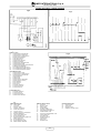
1
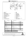
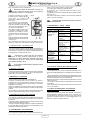
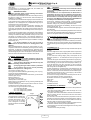
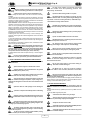
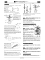
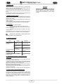
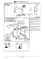
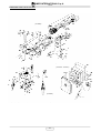
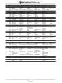
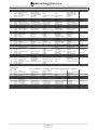
(1140623 - 110 V / 50 Hz - 30 m)
ELEVATORE
HOIST
manuale uso manutenzione ricambi
Operating,maintenance, spare parts manual
IMER INTERNATIONAL S.p.A.
53036 POGGIBONSI (SIENA) - Loc. SALCETO
(ITALY)
Tel. +39.0577.973.41 - Fax +39.0577.983.304
R02 - 2004/01
- Cod. 3213961 -
IMER INTERNATIONAL S.p.A.
TR 225 (110V 50Hz)
Fig.1
LIVELLA
NIVEAU
WATER LEVEL
WASSERWAAGE
NIVEL
1
2
3
4
5
6
7
8
9
10
11
12
13
14
15
16
17
FUNE ACCIAIO
GANCIO
TAMBURO
MOTORE ELETTRICO AUTOFRENENTE
QUADRO ELETTRICO
BRACCIO ESTENSIBILE
TELAIO PORTANTE GIREVOLE
MANIGLIA BLOCCAGGIO
LEVA FINECORSA SUPERIORE
CONTRAPPESO
LEVA BLOCCAGGIO BRACCIO
PERNO SOSTEGNO
COPIGLIA
RIDUTTORE
PULSANTIERA
LEVA FINE CORSA INFERIORE
INTERRUTTORE TERMICO
1
2
3
4
5
6
7
8
9
10
11
12
13
14
15
16
17
DATI TECNICI
ROPE
HOOK
DRUM
BRAKE MOTOR
ELECTRIC PANEL
EXTENDABLE ARM
REVOLVING FRAME
LOCKING HANDLE
LIMIT SWITCH LEVER
ROPE WEIGHT
FRAME LOCKING LEVER
SUPPORT HINGE
SPLIT PIN
GEAR BOX
PENDANT CONTROL
DOWN POSITION CONTROL LEVER
THERMAL OVERLOAD
TECHNICAL DATA
Portata max
Max capacity
kg
200
Velocità media di sollevamento
Lifting speed
m / 1'
19
Altezza max di lavoro
Max working height
m
30
Alimentazione
Nom. voltage
V / Hz
110 / 50
Potenza motore
Motor power
Kw
0.7
Giri motore
R.P.M.
n° / 1'
1320
Assorbimento
Nom. current
A
14
Tipo di servizio
Service type
S3
50 %
Livello di emissione sonora -- LwA
(EN ISO 3744)
Level of noise emission -- LwA
(EN ISO 3744)
dB
79
Livello di pressione sonora -- LpA -- 1,5 m Level of noise pressure -- LpA -- 1,5 m
dB
<70
Peso della macchina
Machine weight
kg
46
Ingombro per l'imballo
Packing dimensions
mm
820x350x500
Norme di progetto
Design standards
DPR 459
del 24.7.96
S.I N°3073 of 30/11/92
FEM 1.001. UNI-ISO 4301-4308-2408 UNI 7670-9466 EN 60204-1
Particolare attenzione deve essere fatta alle avvertenze contrassegnate con questo simbolo :
Special attention must be given to warnings with this symbol:
2
IMER INTERNATIONAL S.p.A.
TR 225 (110V 50Hz)
Caro cliente,
La struttura su cui l elevatore viene applicato deve essere in
grado di sopportare le solleciFig.2
tazioni indicate in fig. 2, che si
generano durante il funzionamento.
IMER dispone di una ampia scelta di supporti, rappresentati in figura 9 -10- 11 - 12 -13 -14, previsti per le diverse applicazioni
di cantiere, progettati in modo da
trasmettere idoneamente alle
MAX
strutture questi carichi.
ci complimentiamo per il suo acquisto dell argano IMER, risultato
di anni di esperienza: è una macchina di massima affidabilità e
dotata di soluzioni tecniche innovative.
OPERARE IN SICUREZZA: É fondamentale ai fini
della sicurezza leggere attentamente le seguenti istruzioni.
Il presente manuale di USO E MANUTENZIONE deve essere custodito dal responsabile di cantiere, sempre disponibile per la consultazione.
Il manuale è da considerarsi parte della macchina e deve essere
conservato per futuri riferimenti (EN 292/2) fino alla distruzione
della macchina stessa. In caso di danneggiamento o smarrimento
potrà essere richiesto al costruttore un nuovo esemplare.
Il manuale contiene importanti indicazioni sulla preparazione del
cantiere, l installazione, l uso, le modalità di manutenzione e la richiesta di parti di ricambio.
Comunque è da ritenersi indispensabile una adeguata esperienza
e conoscenza della macchina da parte del montatore e dell
utilizzatore.
Affinché sia possibile garantire la sicurezza dell operatore, la sicurezza di funzionamento e una lunga durata dell apparecchio, devono essere rispettate le istruzioni del manuale, unitamente alle norme di sicurezza e prevenzione degli infortuni sul lavoro secondo la
legislazione vigente (uso di calzature e abbigliamento adeguati, uso
di elmetti, di cinture di sicurezza, predisposizione di parapetti prospicienti il vuoto, ecc.).
ATTENZIONE
La dichiarazione CE di conformità allegata al presente manuale, è valida solo se vengono utilizzati tutti componenti di
costruzione IMER (elevatore e supporto).
Se questa condizione non è rispettata, tale dichiarazione è
valida solo per l elevatore. Chi esegue l installazione
dell elevatore su un altro tipo di supporto dovrà compilare
una nuova dichiarazione CE di conformità, dopo aver verificato tutti i requisiti contenuti nella Direttiva Macchine 89/392/
CEE e sue successive modifiche ed integrazioni.
Le forze, indicate agli appoggi di ciascun supporto, dovranno
essere considerate nel calcolo di verifica delle strutture di
sostegno (ponteggi, terrazze, soffitti, ecc.) effettuato da tecnico competente.
In caso di applicazione dell elevatore su ponteggio, questo
deve essere opportunamente controventato (vedere fig. 15)
Per l installazione dei diversi supporti, seguire le istruzioni di
cui ciascuno è fornito.
Nel caso si utilizzino dei supporti con portata diversa
dall elevatore, sull insieme dell apparecchio installato dovrà
essere affissa, ben visibile la portata ammissibile in funzione
dell elemento più critico del sistema.
É vietato apportare modifiche di qualsiasi natura alla
struttura metallica o impiantistica della macchina.
IMER INTERNATIONAL declina ogni responsabilità in caso di non
osservanza delle leggi che regolano l uso di apparecchi di sollevamento, in particolare: uso improprio, difetti di alimentazione, carenza di manutenzione, modifiche non autorizzate, manomissioni
e/o danneggiamenti, inosservanza parziale o totale delle istruzioni
contenute in questo manuale.
2.1 PREDISPOSIZIONE DEL POSTO DI LAVORO
- Il lato dell apertura di accesso del carico al piano
deve essere protetto con un parapetto di altezza superiore a
1m ed arresto al piede.
1. DESCRIZIONE GENERALE
AVVERTENZA: Operare con una macchina di sollevamento richiede grande attenzione e perizia, il comando può
essere affidato solo a personale esperto o che abbia ricevuto
le necessarie istruzioni.
- Accertarsi che la corsa di lavoro sia sgombra per tutta l altezza e
prendere le precauzioni necessarie perché nessuno possa sporgersi dai piani intermedi.
- delimitare l area di carico inferiore perché nessuno possa sostarvi durante il sollevamento.
1) La macchina è concepita per il sollevamento di
materiali e per essere utilizzata nei cantieri di costruzioni edili.
3. MONTAGGIO (Fig.1)
2) É vietato l uso per il sollevamento di persone e/o
di animali.
1) Il montaggio dell elevatore, così come il suo utilizzo, richiede personale
esperto o che abbia ricevuto le necessarie istruzioni.
Dato il peso dell elevatore, devono essere impiegati un numero di operatori
tali da non creare situazioni di pericolo durante il suo trasporto ed installazione.
2) L altezza massima di lavoro (30m) è quella relativa alla posizione del
motoriduttore corrispondente al perno superiore del supporto.
3) Posizionare il supporto sulla struttura dell edificio, verificare l allineamento verticale dei perni di sostegno (rif.12) quindi, sollevando la leva di
bloccaggio (rif.11) inserire le boccole del telaio portante (7) sui perni ed
applicare la copiglia di sicurezza (rif.13) antisfilamento.
4) Montare il braccio estensibile (6) sul telaio (7) fino alla posizione di
minima estensione, avvitare la maniglia con rondella nel foro filettato attraverso l asola e serrarla (rif.8).
5) Nel caso di montaggio su supporto a cavalletto, fissare il braccio
estensibile (6) al carrello mediante i fori di fissaggio previsti (rif.fig.14) utilizzando viti e dadi autobloccanti. Seguire per il resto le istruzioni fornite
con il cavalletto.
6) Collegare la pulsantiera a comando diretto (da 1.5m) utilizzando l apposito connettore sul quadro elettrico (5) ed inserire la sicura.
Con il comando in bassa tensione a 24V occorre fissare il quadro elettrico
sul telaio portante (7) con la staffa ed inserire il connettore al quadro (5).
3) Non deve essere utilizzato in ambienti ove esista
il pericolo d esplosioni o incendio o in ambienti di scavi sotterranei.
La macchina è costituita essenzialmente da (fig.1):
- Tamburo montato sull albero del riduttore (rif.3) da una fune metallica (rif.1) da un gancio di sollevamento (rif.2) e contrappeso
(rif.10).
- Motoriduttore composto da un motore elettrico autofrenante (rif.4)
e riduttore ad ingranaggi a bagno d olio (rif.14).
- Impianto elettrico (rif.5).
- Leva di comando fine corsa salita (rif.9).
- Leva di comando fine corsa discesa (rif.16.).
- Telaio portante girevole (rif.7) con braccio estensibile (rif.6) maniglia di bloccaggio (rif.8), leva di bloccaggio telaio (rif.11).
- Interruttore termico (17) che arresta l elevatore quando la corrente supera il valore nominale (per ripristinarlo occorre schiacciarlo).
- L elevatore dispone di 3 tipi di pulsantiere (rif. 15):
. pulsantiera da 1.5 m a comando diretto.
. pulsantiera da 25 m in bassa tensione a 24V.
. pulsantiera da 30 m in bassa tensione a 24V.
Tutti i dispositivi di comando sono dotati di pulsantiera a 3 pulsanti (fig. 3):
2. SUPPORTI PER L ELEVATORE
3
IMER INTERNATIONAL S.p.A.
TR 225 (110V 50Hz)
nero = discesa
bianco = salita
rosso = arresto in caso d emergenza.
7) Liberare il gancio.
dell elevatore.
Fig.3
2) Non permettere che nessuno rimanga sotto un
carico sospeso.
3) Non cercare di sollevare carichi collegati al suolo (es. pali interrati, plinti, ecc.).
4. ALLACCIAMENTO ALLA RETE ELETTRICA
- Verificare che la tensione risulti conforme ai dati di targa della
macchina.
- Verificare inoltre che la tensione di linea sia compresa tra -5% e
+5% del valore nominale con l elevatore in funzione.
- La linea elettrica di alimentazione deve essere provvista sia di
protezione contro le sovracorrenti, sia di tipo differenziale e che il
conduttore di collegamento a terra abbia una sezione come quella
del conduttore. Il dimensionamento dei conduttori deve tener conto delle correnti di funzionamento e della lunghezza della linea per
evitare eccessive cadute di tensione (rif. Tab.1).
Evitare l impiego di prolunghe avvolte a spire sui tamburi.
- Il conduttore di alimentazione deve essere di tipo adatto per frequenti movimenti e rivestimento resistente alla abrasione (per esempio H07RN-F).
- Collegare la spina alla macchina avvitando la ghiera di ritegno
meccanico e grado di protezione IP67.
- L elevatore è così pronto per la prima manovra di collaudo.
4) Assicurarsi che il carico sia ben collegato al gancio dell elevatore e chiudere sempre la sicura (rif.6 fig. 4.1).
5) Se il carico per essere agganciato necessita di
accessori, questi devono essere del tipo certificato ed omologato (cinghie, funi, braghe, ecc.). Dalla portata max deve
essere sottratta il peso di questi accessori.
6) Assicurarsi che non fuoriesca parte del carico
durante le fasi di sollevamento.
7) Prima di sganciare il carico, deve essere verificato che sia appoggiato stabilmente.
8) Non deve essere scaricato un carico sospeso con
accessori che consentano il rilascio istantaneo o tagliando
l imbracatura.
9) Non avvicinare le mani o parti del corpo sul tamburo durante il funzionamento, perché potrebbero rimanere
impigliate nella fune che si avvolge causando gravi infortuni.
5. ISTRUZIONI DI COLLAUDO
10) Non avvicinare le mani o parti del corpo sul contrappeso durante la fase di salita, perchè potrebbero subire
uno schiacciamento con la leva di finecorsa.
- Attenzione!! Questa prova deve essere fatta da
personale esperto e competente e devono essere prese le
necessarie precauzioni per la sicurezza del personale.
11) Evitare l uso della macchina in caso di condizioni ambientali avverse (forte vento o temporali) in quanto il
carico non è guidato.
- Attenzione: il collaudo deve essere eseguito prima dell utilizzo dell elevatore.
Prima di iniziare il collaudo verificare accuratamente che tutta l installazione dell elevatore sia stata eseguita correttamente.
1) Estendere il braccio estensibile alla max estensione e bloccarlo
con l apposita mamopola. Far discendere a vuoto la fune, agendo
sul pulsante di discesa, fino al piano di carico inferiore, verificando
che tutta la corsa sia libera da ostacoli e che a fine corsa, sul
tamburo, restino almeno tre spire avvolte.
2) Prova di ciclo a vuoto. Applicando un piccolo carico (20kg),
verificare il corretto funzionamento della macchina effettuando una
corsa completa di salita e discesa.
Provare i pulsanti di salita, discesa ed arresto, azionamento fine
corsa superiore e corretto avvolgimento del cavo sul tamburo,
azionamento del freno del motore elettrico.
3) Prova di carico. Deve essere eseguita applicando il carico di
portata massima prevista dall elevatore (200 Kg). Effettuare l intera corsa di salita e discesa per verificare gli ancoraggi dell elevatore
e del dispositivo di frenatura del motore elettrico.
Dopo la prova deve essere verificato se nelle strutture sono presenti eventuali cedimenti o assestamenti, ripetendo il controllo dell allineamento orizzontale del tamburo (usando una livella come in
fig.1).
4) L elevatore è provvisto di un dispositivo di sicurezza che arresta
la corsa della macchina nel punto di massima salita (rif. 9) e di
completo svolgimento del cavo (rif. 16) evitando l inversione di
avvolgimento sul tamburo.
É buona norma evitarne l intervento arrestando la macchina rilasciando il relativo pulsante di comando.
12) La posizione di comando e le condizioni di illuminazione devono consentire la perfetta visibilità del carico
per tutta la corsa di lavoro.
ATTENZIONE!! L intervento del finecorsa di discesa può avvenire o per altezza di utilizzo con conforme o per
altri problemi che possono compromettere l integrità
dell elevatore. Dopo il suo intervento è necessario un controllo dell installazione e dei componenti dell elevatore (fune,
tamburo, albero, fune, ecc.).
Al termine della prova deve essere riportata la data, la verifica della
installazione e la firma sul verbale dei controlli (Tab.2) ed eventuali
osservazioni..
22) Quando un carico deve essere sollevato o abbassato, il comando deve essere tale da minimizzare movimenti pericolosi sia laterali che verticali.
La procedura di collaudo indicata, completa della
prova di ciclo a vuoto 2) e carico 3), dovrà essere effettuata
ad ogni nuova installazione della macchina.
24) In caso d utilizzo del telecomando da 25m o
da 30m, il cavo della pulsantiera deve essere bloccato
alla struttura d ancoraggio per evitari probabili rotture.
13) Assicurarsi che tutte le protezioni siano al loro
posto.
14) Durante l uso controllare che la fune di acciaio
si avvolga in maniera corretta, spira contro spira, senza
allentamenti o accavallamenti, che sono cause di danni alla
fune stessa. Se ciò avvenisse svolgere la fune e riavvolgere
in maniera corretta tenendola in tensione.
15) Accertarsi che la corsa di lavoro sia sgombra
da ostacoli per tutta l altezza e prendere le precauzioni necessarie perchè nessuno possa sporgersi dai piani intermedi.
16) Delimitare l area di carico inferiore perchè nessuno possa sostarvi durante il sollevamento.
17) Tenere i bambini a distanza dall elevatore.
18) Quando l elevatore non viene utilizzato, non
permettete che persone estranee possono usarlo.
19) É vietato l impiego dell elevatore per trazioni
oblique (superiore a 5° rispetto alla verticale).
20) É vietato ruotare l elevatore sui perni tirandolo
per la pulsantiera: deve essere ruotato manualmente dal telaio.
21) Non lasciare un carico sospeso incustodito.
Sollevarlo o abbassarlo e scaricarlo.
23) Durante il sollevamento o abbassamento non
permettete che ilcarico cominci a ruotare: potrebbe rompersi.
6. RACCOMANDAZIONI D USO E DI SICUREZZA
25) Prima di lasciare l elevatore incustodito,
togliere il carico, avvolgere completamente la fune sul
1) Non sollevare carichi superiori alla portata
4
IMER INTERNATIONAL S.p.A.
TR 225 (110V 50Hz)
tamburo e quindi scollegare la presa d alimantazione
elettrica.
Inserire la nuova fune nel foro e farla
uscire dall'asola del tubo del tamburo,
quindi serrare il morsetto all'estremità,
lasciando circa 1 cm di fune libera (fig.
4.2), tirare la fune finché il manicotto
arriva a contatto con la parete interna
del tamburo.
Avvolgere due spire complete mantenendo la fune a contatto del tamburo
(fig. 4.3).
Ogni qualvolta si riprende il lavoro, dopo un periodo di sosta
prolungata (es. pausa notturna), è necessario verificare
l elevatore prima di iniziare il lavoro, eseguendo una prova di
ciclo a vuoto (secondo le indicazioni riportate nel punto 2, CAP.
5).
7. VERIFICHE E MANUTENZIONI
Fig. 4.3
Attenzione!! Tutti gli interventi di manutenzione devono essere eseguiti dopo aver fermato la macchina, tolto il carico e scollegata la presa di alimentazione elettrica.
- Le riparazioni devono essere effettuate da personale competente o nei Centri Assistenza IMER.
- Per la sostituzione di parti guaste utilizzare esclusivamente
ricambi originali.
- Controllare ogni 6/7 giorni l efficacia del freno del motore elettrico.
Al completamento della seconda
spira far passare la fune sotto il
gancio presente all interno dell asola del tamburo (fig. 4.4).
Tirare la fune fino ad assicurarsi il
contatto su tutta la circonferenza
del cilindro.
Avvolgere la fune disponendo correttamente spira contro spira in
stati successivi.
Fig. 4.4
Infilare la fune d acciaio nel
contrappeso e nel bozzello
a cuneo (fig. 4.5).
Ripassare la fune d acciaio
nel bozzello a cuneo e nel
contrappeso.
Inserire il cuneo tra il bozzello
e la fune d acciaio.
Tirare la fune fino a stringere tra di loro tutti i componenti. Quindi bloccare la fune con
morsetto ad U , facendo rimanere la parte piana a contatto
con la fune di trazione.
- Mantenere sempre leggibili le scritte e le
segnalazioni sulla macchina.
- Rimuovere ogni sporcizia che si depositasse
sulla macchina.
- Mantenere sempre efficiente il funzionamento del finecorsa di salita e discesa verificandoli all inizio di ogni turno di lavoro.
- Assicurarsi sistematicamente dello stato del
cavo elettrico ogni qualvolta si inizia l uso della macchina, qualcuno inavvertitamente e/o inconsapevolmente potrebbe averlo danneggiato.
Fig. 4.5
7.1 FUNE D ACCIAIO
Utilizzare esclusivamente funi nuove, con caratteristiche conformi a quanto di seguito prescritto, dotate di attestato di conformità ed identificazione.
- Diametro esterno
(mm)
5
- Formazione
133 fili (19x7) antigiro
- Senso avvolgimento
crociato dx
- Resistenza filo elementare (N/mm²)
1960
- Carico minima rottura fune (kN)
16.07
- Lunghezza
(m)
31
- Trattamento superficiale
zincata ingrassata
- Il codice Rif. IMER è riportato nella tabella ricambi.
Fig. 4.1
Fig. 4.2
Procedere al montaggio del gancio sul bozzello a cuneo, bloccandolo con vite e dado autobloccante.
Verificare che il fine corsa di salita funzioni quando il contrappeso urta la leva.
Effettuare la prova di carico indicata nel paragrafo 5.
7.1.1 SOSTITUZIONE
DELLA FUNE (Fig.4)
La sostituzione deve essere
effettuata da un manutentore
competente.
Smontare il gancio (rif. 4) svitando il bullone (rif. 5).
Smontare il morsetto (rif. 1),
spingere la zeppa (rif. 2) e
sfilare la fune dal bozzello a
cuneo (rif. 3).
7.1.2 CONTROLLI PERIODICI
Verificare visivamente lo stato della fune giornalmente od ogni qual volta si presentino sollecitazioni anomale (attorcigliamenti, forti incastri nelle spire,
piegature o sfregamenti).
Sostituire la fune in presenza dei difetti indicati in fig.16.
Trimestralmente esaminare accuratamente l intera fune ed in
particolare i punti terminali registrandone il risultato nella scheda nel manuale Tab.2 che deve essere conservato dal responsabile di cantiere.
Procedere alla sostituzione almeno ogni anno.
Il tamburo è dotato di un dispositivo per far restare due spire di
fune completamente avvolte anche quando è completamente
svolta, per evitare di forzare il punto d attacco della fune stessa.
Nella sostituzione della fune occorre montarla in modo da rispettare questa condizione.
Svolgere completamente la fune. Sfilarla dall interno del tamburo attraverso l apposito foro ed asola presenti.
7.2 REGOLAZIONE DEL FRENO MOTORE (Fig. 5)
Il freno a disco ad azionamento meccanico, interviene in mancanza dell alimentazione elettrica al dispositivo magnetico di
apertura.
In caso di riduzione della capacità frenante occorre far controllare dal manutentore competente l apparecchio che, se neces-
5
IMER INTERNATIONAL S.p.A.
TR 225 (110V 50Hz)
sario provvederà alla sua registrazione.
rativa, occorre seguire almeno le seguenti fasi:
a) scaricare l olio utilizzando l apposito tappo;
b) separare i vari componenti plastici ed elettrici (cavi,
pulsantiera, ecc.);
c) suddividere i componenti metallici per tipo di metallo (acciaio,
alluminio, ecc.);
Una volta così suddiviso, smaltire i vari componenti utilizzando
centri di raccolta autorizzati.
Attenzione!! Prima di intervenire sul freno assicurarsi che il carico sia staccato e che la sua spina di
alimentazione elettrica sia scollegata.
Togliere il copriventola (A), regolare
Fig. 5
il traferro (d) tra il magnete (B) ed il
disco freno (C) usando uno
spessimetro: il traferro (d) deve essere 0.4 mm.
La misurazione dovrà essere effettuata su tre punti diversi in modo da
verificare il parallelismo del disco facendo scivolare leggermente avanti e indietro lo spessimetro.
Se il traferro è troppo grande, ridurlo avvitando il dado (D) con chiave
esagonale. Se il traferro è piccolo,
aumentarlo svitando il dado (D). Misurare più volte la nuova distanza
(d).
Quando la distanza è stata regolata
conformemente alle dimensioni sopra elencate, riposizionare la
copertura (A).
Per controllare la tenuta dei freni, dopo aver effettuato la registrazione, verificare più volte l azione frenante a pieno carico.
7.3 LUBRIFICAZIONE
Non disperdere nell ambiente, possono causare incidenti od inquinamento.
11. INCONVENIENTI / CAUSE / RIMEDI
INCONVENIENTI
Premendo i pulsanti
di azionamento
(salita o discesa) la
macchina non
funziona.
MOTORIDUTTORE
- Non devono esserci perdite di olio dal gruppo motoriduttore: la
presenza di vistose perdite può significare lesioni nella struttura di alluminio. In questo caso procedere immediatamente all
ermetizzazione o sostituzione del carter.
CAUSE
Il pulsante di
emergenza è premuto.
Non arriva tensione
alla macchina.
La presa e la spina
elettrica non sono ben
collegate.
E' intervenuto
l' interruttore di
protezione del quadro
esterno di
alimentazione.
E' intervenuto l'
interruttore termico
contro il sovraccarico
del motore.
Interruttore termico Tensione di linea
bassa.
che interviene
frequentemente.
La maniglia di
Scorrimento
orizzontale faticoso bloccaggio è stretta.
della prolunga
telescopica.
Se l' inconveniente persiste
- Controllare il livello dell olio del riduttore
attraverso la spia, prima di ogni messa in opera.
Rabboccare in caso di mancanza. Cambiare l olio dopo
circa 2000 ore di lavoro. Usare olio da ingranaggi
viscosità ISO VG 460 a 40° C.
RIMEDI
Disattivare il pulsante
ruotandolo.
Controllare la linea.
Ripristinare il corretto
collegamento.
Ripristinare il
magnetotermico.
Ripristinare premendo il
pulsante.
Verificare i parametri
indicati nel paragrafo 4.
Allentare.
Rivolgersi all'
Assistenza IMER.
- L olio esausto è rifiuto speciale, pertanto va smaltito a norma di legge.
12. IN CASO DI GUASTO DELLA MACCHINA CON
CARICO SOSPESO
7.4 IMPIANTO ELETTRICO
- Se possibile, rimuovere il carico accedendo dal livello in cui si
trova, quindi togliere l elevatore e provvedere alla sua manutenzione.
- Altrimenti utilizzare un altro apparecchio di sollevamento (di portata sufficiente) posto più in alto, sospendere l apparecchio guasto
sia nella zona del carico che vicino agli attacchi.
Sollevarlo lentamente in modo da liberarlo dagli attacchi, quindi
calare tutto a terra.
- Non tentare di agire sul dado di regolazione del freno perchè
sfuggirebbe.
- Non cercare di riparare il guasto intervenendo sulla macchina
con carico sospeso.
Controllare l integrità della custodia isolante della pulsantiera
provvedendo alla sua sostituzione, in caso di danneggiamento
della tenuta, con ricambio originale IMER.
8. SMONTAGGIO ELEVATORE
Togliere qualsiasi carico dal gancio dell elevatore.
Avvolgere completamente la fune metallica sul tamburo.
Scollegare la presa di alimentazione elettrica. Scollegare la
pulsantiera (o il telecomando) dal quadro elettrico per mezzo
dell apposito connettore.
Svitare la maniglia di bloccaggio ed estrarre il braccio estensibile.
Togliere la copiglia sul perno di sostegno e sfilare il telaio portante
girevole.
Con il cavalletto, il carrello deve essere smontato dall elevatore
quando è stato tolto dalle guide e prima di togliere la zavorra.
13. LIVELLO DI RUMOROSITA ALL ORECCHIO
DELL OPERATORE
Il livello Lp(A) indicato nella tabella DATI TECNICI corrisponde al
livello equivalente ponderato di pressione sonora in scala A previsto dalla 98/37/CE. Tale livello è misurato a vuoto, alla testa dell operatore in posizione di lavoro a 1,5 metri dall apparecchio, considerando le diverse condizioni di lavoro.
9. TRASPORTO E MESSA FUORI ESERCIZIO
- Non lasciare incustodito l elevatore installato senza aver tolto
la linea di alimentazione elettrica e riavvolta la fune interamente
sul tamburo.
Lasciando inattiva la macchina per lungo tempo è buona norma
tenerla protetta dagli agenti atmosferici.
- Durante il trasporto proteggere dagli urti e dallo schiacciamento
le varie parti della macchina che possono compromettere la sua
funzionalità e resistenza meccanica
10. ROTTAMAZIONE DELL ELEVATORE
Per la rottamazione dell elevatore, al termine della sua vita ope6
IMER INTERNATIONAL S.p.A.
TR 225 (110V 50Hz)
Dear Client
Congratulations on choosing the IMER hoist, the reliable and
innovative result of years of experience.
WARNING
The EC Declaration of Conformity enclosed with this manual
is only valid if only IMER components are used for the winch
and support.
If this condition is not complied with, the Declaration is
applicable to the winch only. The installation technician who
fits the winch an another type of support must compile a new
EC Declaration of Conformity after having satisfied all the
provisions of the Machinery Safety Directive 89/392/EEC and
its subsequent modifications and supplements.
These forces - referred to support couplings - must be accounted
for in calculations related to supporting structures (scaffolding,
balconies, ceilings, etc.), made by a qualified technician.
If the winch is to be secured to scaffolding, never fit it to a free
standing upright (Fig. 15).
To install the various supports, follow the instructions applying to
each assembly.
When using supports with load bearing capacities other than that
of the hoist, the permissible load bearing capacity of the weakest
element of the system must be prominently displayed.
WORKING IN SAFETY
To work in complete safety, read the following instructions
carefully before installing the hoist.
This operation and maintenance manual must be kept on site by
the person in charge, e.g. the site foreman, and must always be
available for consultation.
The manual is to be considered an integral part of the machine and
must be kept for future reference (EN 292/2) until the machine is
disposed of. If it is damaged or lost, a replacement copy may be
requested from the hoist manufacturer.
The manual contains important information regarding site
preparation, installation, operation, maintenance, and ordering of
spare parts. Nevertheless, the installer and the operator must both
have adequate experience and knowledge of the machine prior to
use.
To guarantee the complete safety of the operator, safe operation
and long life of equipment, follow the instructions in this manual
carefully, and observe all safety standards currently in force for the
prevention of accidents at work with particular reference to
suspended loads and fall equipment (use of suitable footwear and
clothing, hard hats, safety harnesses, proper installation of railings
around drops, etc.).
2.1 INSTALLING THE HOIST ON SITE
- The load access to the floor must be protected by
a rail over 1m high and a foot stop.
- Make sure that the lifting run is free from obstacles, and ensure
that nobody can lean out into the hoistway from intermediate floors.
- Cordon off the ground loading area to prevent interference with
work.
It is strictly forbidden to carry out any form of
modification to the steel structure or working parts of the
machine.
IMER INTERNATIONAL declines all responsibility for noncompliance with laws and standards governing the use of lifting
equipment, in particular; unprogrammed use, defective power
supply, lack of maintenance, unauthorised modifications, tampering
with or damage to part or all of the equipment, and partial or total
failure to observe the instructions contained in this manual.
3. ASSEMBLY (Fig.1)
1) Only competent, trained personnel may assemble and operate
the hoist.
Given the weight of the hoist, an appropriate number of personnel
must be used for handling and installing it so as to avoid hazardous
situations.
2) The maximum working height (30m) corresponds to the
gearmotor position i.e. is measured from the top hinge of the
support.
3) Secure the support to the building and check the support pins
vertical alignment (12); then lift the locking lever (11) to insert the
frame bushings (7) onto the pins and fit the split pin retainer (13).
4) Fit the telescopic arm (6) to the frame (7) at its minimum
extension, screw on the locking handle and washer in the threaded
hole through its slot and tighten fully.
5) When assembling on a trestle support, fit the telescopic arm (6)
to the carriage through the securing holes (14) using bolts and
locknuts. For the rest, follow the instructions for the trestle support.
6) Insert the direct pendant control (1.5 m lead) plug in the electrical
panel (5) and turn on the main switch
For the 24V low voltage pendant fix the electrical panel on the frame (7) and insert the connector in the panel (5).
All pendant controls have 3 pushbuttons (Fig. 3):
black: down
white: up
red: emergency stop.
Fig.3
7) Release the hook.
1. GENERAL DESCRIPTION
ATTENTION: Use of lifting equipment requires care
and skill. The machine must be operated by skilled and
properly instructed personnel only.
1) The machine is designed to lift materials only and
for use on building construction sites.
2) Carrying passengers and/or animals is prohibited.
3) The machine must not be used in potentially
explosive atmospheres or underground.
The machine consists of (fig. 1):
Drum type winch fitted to reduction gear shaft (3), wire rope (1),
lift hook (2) and counterweight (10).
Gearmotor consisting of an electric brake motor (4) and oil bath
reduction gear unit (14).
Electrical system (5).
UP position control lever (9).
DOWN position control lever (16).
Rotary frame (7) with telescopic arm (6), loocking handle (8) and
frame locking lever (11).
Thermal overload (17) which stops the winch when the current
exceeds the nominal value (press to reset).
The winch has two types of pendant control (15)
1.5 m lead direct pendant
25 m low voltage (24V) pendant.
30 m low voltage (24V) pendant.
2. WINCH SUPPORTS
Fig.2
The structure supporting the
4. CONNECTION TO THE MAINS
- Make sure that the mains voltage is the same as that specified on
the dataplate.
- Also check that the mains voltage is within the range -5% to +5%
of the nominal operating value.
- The power cable must be fitted with an overload circuit breaker or
fuse and a RCCD, the earth wire must have the same cross-section
as the power cable.
The conductors must be dimensioned in proportion to both the
operating current and their length to avoid voltage drops (Table 1).
Do not use extension leads wound on drums. Make sure that any
extension cable connections are dry and safe.
- The power cable must be suitable for frequent handling and have
an abrasion-resistant sleeve (for example H07RN-F).
- Insert the plug into the machine and tighten the securing collar
(IP67 protection).
- The hoist is now ready for testing.
winch must withstand the loads
generated during operation (Fig.
2). IMER offers a wide range of
supports (see figures 9-10-1112-13-14) for use on building
sites, designed to suitably
transfer the loads to the building
structures.
MAX
7
IMER INTERNATIONAL S.p.A.
TR 225 (110V 50Hz)
5. TESTING
12) The entire lifting run and the load itself
must be visible from the operating position and
adequately illuminated.
- Warning! Testing must be carried out by qualified
personnel. Take all necessary precautions to ensure personal safety.
13) Ensure that all the guards are in place.
- Warning! The winch must be tested before use.
Before testing the hoist make sure that it has been correctly
installed.
1) Extend the jib to its maximum and lock into position. Using the
down botton lower the hook (without load) to the bottom of the
hoistway and make sure that it is clear of obstructions and at least
three turns of rope remain on the drum.
2) No-load test. Load the hoist with 20 Kg and check the correct
operation of the hoist by raising and lowering the load through its
entire run once (checking the correct operation of up and down
bottons, stop button, UP limit switch operation and the correct
winding of the rope on the drum. Check the operation of the brake.
3) Load test. Load the hoist with its maximum admissible load
(200 Kg). Lift and lower the hoist through its entire run to test the
support structures and brake.
Following the test, check the security of the mountings and
supports. Check again the horizontal alignment of the hoist with a
spirit level.
4) The hoist is fitted with a safety which stops travel at the UP (9)
and fully unwound positions (16) to avoid the rope winding on in
the wrong direction.
Do not depend on this safety to stop the winch; release the control
button to stop the winch instead.
14) Check that the rope winds on correctly, one turn
at a time without slack or overlay which might damage the
rope itself. If it is not correctly wound on, unwind the rope
and rewind it correctly under tension.
15) Make sure that lifting run is free from obstacles,
and be sure that nobody can lean forward on intermediate
floors.
16) Enclose ground loading area to prevent people
from interfering with work.
17) Do not allow children access to the hoist.
18) When the hoist is not being used, do not allow
unauthorised persons access to it.
19) The hoist may not be used for pulling loads
obliquely (exceeding 5° with respect to vertical lifting).
IMPORTANT!! Down limit switch (16) activation can
occur either due to incorrect working height or due to other
problems which may prejudice correct hoist functioning. After
the limit switch has been activated, the hoist installation and
components must be checked (rope, drum, shaft etc.)
If satisfied with the test results complete the entry in the site register
(Tab. 2).
20) Do not pull on the pendant control to turn the
hoist; use the frame for this purpose, turning it by hand.
21) Do not leave a suspended load unattended. Lift
it or lower it and off load it.
In case of new installations and after every service,
repeat the no-load (2) and load (3) tests described above.
22) When lifting or lowering a load use a smooth
action to minimise dangerous vertical or sideways
movements of the load.
6. SAFETY WARNINGS AND OPERATING PRECAUTIONS
1) Do not lift weights in excess of the maximum
admissible load.
23) Do not allow loads to spin while lifting or
lowering. The cable could be dameged.
2) Do not allow anyone to stand under a load.
24) With 25m or 30m low voltage pendant:
fasten the cable to the structure,otherwise it could break.
3) Never attemps to lift loads attached to the ground
(e.g. embedded poles, plinths, ect.).
4) Make sure that the load is always well secured to
the hook and close the safety catch (Fig. 4.1 ref. 6).
25) Lower and stop the hoist, remove the load, wind
the rope completely onto the drum and then unplug before
leaving the hoist unattended.
When operation is resumed after a lengthy period of disuse the
entire machine must be tested under no-load conditions before
starting, as described above (point 2, CAP.5).
5) If accessories are required for lifting, ensure that
they are certified and approved (belts, ropes, slings etc.).
Subtract the weight of accessories from the maximum load
capacity.
7. TESTING AND MAINTENANCE
Warning!! Only carry out maintenance with the
machine switched off, unloaded and disconnected from the
mains.
- Repairs must be done by qualified personnel or by IMER Technical
Service.
- Use only IMER original spare parts.
6) Ensure that no load spillage occurs during lifting.
7) Ensure complete load stability before unhooking
the load.
- Check the motor brake every 6/7 days.
8) Never unload a suspended load with accessories
that cause immediate release and never cut slings to remove
the load.
- Ensure that the notices and inscriptions on the
machine are prominently displayed and legible.
9) Keep hands and other parts of the body well clear
of the drum during operation to avoid getting caught in the
winding rope and seriously injured.
- Keep the machine clean of dirt.
- Check the operation of the UP and DOWN position
limit switches at the start of each work shift.
10) Keep hands and other parts of the body well
clear of the counterweight during lifting to avoid crushing
against the stop lever.
- Check the electrical cable at the start of every work
cycle for accidental damage.
11) Do not use the machine in bad weather (strong
wind or storms) as the load is not guided.
8
IMER INTERNATIONAL S.p.A.
TR 225 (110V 50Hz)
Fig. 4.5
7.1 WIRE ROPE
Only use new ropes as specified below, complete with certificate
of conformity and identification.
External diameter
(mm)
5
Type
133 wires (19x7) anti-spin
Direction of lay
dx
Strand strength
(N/mm2)
1960
Minimum breaking strain
(kN)
16.07
Length
(m)
31
Surface treatment
galvanised, greased
The IMER reference code is given in the spare parts table.
Fig. 4.1
Check that the UP limit switch operates when the counterweight
touches the lever.
Run the load test described in paragraph 5.
7.1.1 REPLACING THE
ROPE (Fig. 4)
The rope must be replaced by
a qualified service technician.
Remove the hook (4) by
unscrewing bolt (5).
Remove the clamp (1), push on
the wedge (2) and extract the
rope from the block (3).
7.1.2 PERIODIC CHECKS
Visually check the condition of the rope every
day and whenever it is subjected to abnormal strain
(twisting, bending, kinks or abrasion).
Replace the rope when defective (Fig. 16).
Inspect the entire rope carefully every three months and in
particular the ends; note the results in the chart (Table 2) which
must be kept by the site foreman.
Replace the rope at least once a year.
7.2 ADJUSTING THE MOTOR BRAKE (Fig.5)
The brake is of the no-power engagement type.
If its braking power is reduced a
Fig. 5
qualified technician must check the
device and adjust it.
Fig. 4.2
The drum is fitted with a device which
ensures that 2 turns of rope are always
wound on even when the rope is
unwound to its limit. This stops the rope
attachment from being over-forced.
The rope must be attached in this way.
Completely unwind the rope. Extract
from the inside of the drum through the hole and slot.
Insert the new rope in the hole ahd thread it through the slot in
the drum tube. Tighten the clamp at the end, leaving about 1 cm
of rope free (Fig. 4.2), and pull the rope until the clamp comes
in contact with the innner wall of the drum.
Warning!!
Before
servicing the brake make sure
that the winch is not loaded and
that the brake s power supply is
disconnected.
Remove fan cover (A), and adjust the
air gap d between magnet (B) and
brake disk (C) by means of a feeler
gauge.
The gap (d) must be 0.4 mm.
Measurement should be taken at three
points in order to check that the disc
is perfectly parallel to the magnet.
Slide the feeler gauge lightly backwards and forwards. If the
air gap is too wide, reduce it by tightening nut D with a ring
spanner. Check distance d several times. If the air gap is too
small, increase the it by unscrewing nut D .
Once the air gap has been correctly adjusted, refit cover A .
To check braking power, after carrying out the adjustment,
repeatedly test braking action under full load conditions (ref.
para. 5).
Fig. 4.3
Wind on two complete turns keeping
the rope in contact with the drum
(Fig. 4.3).
Fig. 4.4
On the second turn pass
the rope under the hook
inside the drum slot (Fig.
4.4).
Tension the rope for good
contact with the drum
surface.
Now wind on the rope in
adjacent turns, one layer at a time.
7.3 GEARMOTOR LUBRICATION
- The gearmotor unit must not develop oil leaks. Leaks may
indicate damage to the aluminium casing. In this case, reseal or
replace the casing.
- Check the gearmotor oil level through the
sight glass before every start up or long storage. Refill
as required. The oil should be changed every 2000 hours.
Use gear oil with ISO VG 460 viscosity at 40°C.
Insert the wire rope into the counterweight and the block (Fig.
4.5).
Pass the rope back through the counterweight and the block.
Insert the wedge between the block and the rope.
Pull the rope to tighten all components. Now lock the rope with a
U-clamp so that the flat part remains in contact with the lifting section
of the rope.
Fit the hook to the block and tighten the bolt and locknut.
- Used oil is classed as special waste. As such, it
must be disposed of in accordance with the established
legislation.
7.4 ELECTRICAL SYSTEM
Check the condition of the pendant control case and cable , if
damaged it should be replaced with the IMER spare part.
9
IMER INTERNATIONAL S.p.A.
TR 225 (110V 50Hz)
8. DISMANTLING
Unload the hook.
Wind the wire rope completely onto the drum. Disconnect the
machine from the mains. Disconnect the pendant control (or
remote control) from the electrical panel.
Unscrew the locking handle and extract the telescopic arm.
Remove the split pin on the support pin and extract the revolving
frame.
If a trestle is being used, the hoist unit must be removed from the
carriage after it has been removed from the beam.
WARNING!
Additional measures shall be taken to
prevent any person falling or any person
being struck by falling object, according
to the relevant regulations in the country
of use.
9. TRANSPORT AND STORAGE
- Do not leave the installed hoist unattended without having first
wound the rope completely onto the drum and disconnected the
electrical power supply.
When storing the machine for a long period of time, protect it from
weather conditions.
- During transport, protect the machine from blows and crushing to
avoid compromising its functionality and mechanical strength.
10. SCRAPPING
In case of scrapping, proceed as follows:
a) drain off all oil by means of the relative oil plug;
b) separate all plastic and electrical components (cables,
pendant control, ect.);
c) divide all metal components according to type (steel,
aluminium, ect.).
On completion of the above, dispose of all components at authorised
waste disposal centres, in compliance with current legislation.
Respect the environment: certain parts can be
harmful to persons or the environment.
11. TROUBLESHOOTING
FAULT
The machine does
not lift or lower on
command
CAUSE
Emergency stop button
engaged
No power to machine
Plug not inserted
Power board cutout
tripped
Thermal overload
switch tripped
Thermal cutout trips Low mains voltage
frequently
Difficult to lengthen Lock knob too tight
the telescopic arm
IF THE FAULT PERSISTSContact IMER
Technical Service
SOLUTION
Turn to disengage
Check mains cable
Insert the plug
Reset the overload trip
Reset by pushing the
button
Check the parameters in
Paragraph 4
Slacken
Contact IMER Technical
Service
12 . PROCEDURE IN CASE OF FAULT WITH LOAD
SUSPENDED
- If possible remove the load from the nearest level, then
dismantle the hoist and service it.
- If this is not possible, use another lifting machine (with adequate
load bearing capacity) from higher up and suspend the faulty hoist
both at the load and at the hoist attachment point.
Remove the split pin and lift the faulty hoist slowly off its fitting,
then lower the entire load to the ground.
- DO NOT adjust the motor brake with the load suspended as it
would be uncontrollable.
- DO NOT try to service the machine with the load suspended.
13. NOISE LEVEL AT THE OPERATOR S EAR
The level Lp(A) given in the TECHNICAL DATA chart
corresponds to the weighted equivalent sound pressure level
on scale A of European Directive 98/37. This level is measured
with no load, at the operator s head in the working position 1.5
metres away from the instrument, considering the different
working conditions.
10
IMER INTERNATIONAL S.p.A.
TR 225 (110V 50Hz)
SCHEMA ELETTRICO - WIRING DIAGRAM
Fig.8
Fig.7
I
QUADRO (FIG.8)
PE
CONDUTTORE DI PROTEZIONE
L1
CONDUTTORE DI LINEA FASE
N
CONDUTTORE DI LINEA NEUTRO
F1
INTERRUTTORE TERMICO
S4
FINECORSA DISCESA
S5
FINECORSA SALITA
X1
CONNETTORE COMANDI
X3
MORSETTI MAGNETE
X4
CONNETTORE CONDENSATORE
X5
CONNETTORE MOTORE
X6
CONNETTORE ALIMENTATORE MAGNETE
S
ALIMENTATORE MAGNETE
AS
AVVOLGIMENTO MOTORE SALITA
AD
AVVOLGIMENTO MOTORE DISCESA
AM
AVVOLGIMENTO MAGNETE FRENO
Fig.6
110 V
TELECOMANDO (FIG.6)
L1
CONDUTTORE DI LINEA
N
CONDUTTORE DI LINEA NEUTRO
PE
CONDUTTORE DI PROTEZIONE
T1
TRASFORMATORE
X1
CONNETTORE
X2
MORSETTIERA
F2
FUSIBILE TRASF. (INGRESSO)
F3
FUSIBILE TRASF. (USCITA)
K1
RELE' ARRESTO
K2
RELE' DISCESA
K3
RELE' SALITA
S1
PULSANTE ARRESTO
S2
PULSANTE DISCESA
S3
PULSANTE SALITA
PULSANTIERA (FIG.7)
S1
PULSANTE ARRESTO
S2
PULSANTE SALITA
S3
PULSANTE DISCESA
X1
CONNETTORE COMANDI
GB
SWITCHBOARD (FIG.8)
PE
EARTH WIRE
L1
LIVE WIRE
N
NEUTRAL WIRE
F1
THERMAL OVERLOAD
S4
DOWN LIMIT SWITCH
S5
UP LIMIT SWITCH
X1
PENDANT CONTROL CONNECTOR
X3
MAGNET TERMINALS
X4
CAPACITOR CONNECTOR
X5
MOTOR CONNECTOR
X6
MAGNET POWERING CONNECTOR
S
BRAKE RECTIFIER
AS
MOTOR WINDING, UP
AD
MOTOR WINDING, DOWN
AM
BRAKE MAGNET WINDING
REMOTE CONTROL (FIG.6)
L1
LIVE WIRE
N
NEUTRAL WIRE
PE
EARTH WIRE
T1
TRANSFORMER
X1
CONTROL CONNECTOR
X2
SWITCHBOARD TERMINALS
F2
TRANSFORMER. FUSE
F3
AUXILIARY TRANSFORMER. FUSE
K1
STOP CONTACTOR
K2
UP CONTACTOR
K3
DOWN CONTACTOR
S1
STOP BUTTON
S2
UP BUTTON
S3
DOWN BUTTON
11
CONTROL BOARD (FIG.7)
S1
STOP BUTTON
S2
UP BUTTON
S3
DOWN BUTTON
X1
PENDANT CONTROL PLUG
IMER INTERNATIONAL S.p.A.
TR 225 (110V 50Hz)
PUNTELLO PER INTERNI
POTEAU POUR INTERIEUR
HOIST FRAME FOR INTERMEDIARY FLOORS
INNENSTÜTZE
PUNTAL PARA INTERIORES
Fig. 9
POSIZIONE APPOGGIO SUPERIORE
POSITION D'APPUI SUPÈRIEURE
POSITIONING TOP FOOTANORDNUNG
DER OBEREN AUFLAGE
POSICION APOYO SUPERIOR
TRAVE
POUTRE
BEAM
TRÄGER
VIGA
ELEVATORE
APPAREIL DE LAVAGE
HOIST
AUFZUG
ELEVADOR
TRAVE
POUTRE
BEAM
TRÄGER
VIGA
LIVELLA
NIVEAU
SPIRIT LEVEL
WASSERWAAGE
NIVEL
PARAPETTO
PARAPET
PARAPET
BRÜSTUNG
PARAPETO
ZONA LAVORO OPERATORE
ZONE DE TRAVAIL OPÉRATEUR
OPERATOR WORK ZONE
ARBEITSBEREICH
DES
BEDIENERS
ZONA DETRABAJO OPERADOR
cod. 1199102 - cod. 1199115
KIT PER PUNTELLO DA ESTERNI
KIT POUR POTEAU D' EXTERIEUR
HOIST FRAME FOR ROOFS
BAUSATZ AUßENSTÜTZE
KIT PARA PUNTAL DE EXTERIORES
CONTENITORE ZAVORRA
CONTENEUR LEST
COUNTER WEIGHT
BALLAST
CONTENEDOR DE CONTRAPESO
Fig. 10
CONTENITORE ZAVORRA
CONTENEUR LEST
COUNTER WEIGHT
BALLAST
CONTENEDOR DE CONTRAPESO
PARAPETTO
PARAPET
PARAPET
BRÜSTUNG
PARAPETO
CONTENITORE ZAVORRA
CONTENEUR LEST
COUNTER WEIGHT
BALLAST
CONTENEDOR DE CONTRAPESO
LIVELLA
NIVEAU
SPIRIT LEVEL
WASSERWAAGE
NIVEL
ELEVATORE
APPAREIL DE LAVAGE
HOIST
AUFZUG
ELEVADOR
ZONA LAVORO OPERATORE
ZONE DE TRAVAIL OPÉRATEUR
OPERATOR WORK ZONE
ARBEITSBEREICH
DES
BEDIENERS
ZONA DETRABAJO OPERADOR
kg 530
PARAPETTO
PARAPET
PARAPET
BRÜSTUNG
PARAPETO
ATTACCO A PONTEGGIO
FIXATION SUR ECHAFAUDAGE
HOIST FRAME FOR SCAFFOLDING
GERÜSTBEFESTIGUNG
CONEXIÓN PARA ANDAMIO
POSIZIONE DI LAVORO
POSITION DE TRAVAIL
WORK POSITION
ARBEITSPOSITION
POSICION DE TRABAJO
cod. 1199134
cod. 1199131
Fig. 11
Ø 48
ZONA LAVORO OPERATORE
ZONE DE TRAVAIL OPÉRATEUR
OPERATOR WORK ZONE
ARBEITSBEREICH
DES
BEDIENERS
ZONA DETRABAJO OPERADOR
ELEVATORE
APPAREIL DE LAVAGE
HOIST
AUFZUG
ELEVADOR
POSIZIONE DI LAVORO
POSITION DE TRAVAIL
WORK POSITION
ARBEITSPOSITION
POSICION DE TRABAJO
- PROLUNGA PER PUNTELLO
- RALLONGE POUR POTEAU
- JIB EXTENSION FOR INTERMEDIARY FLOOR
AND ROOF FRAMES
- SCHWENKARM FÜR-GESCHOßSTÜTZE
- ALARGADOR PARA PUNTAL
cod. 1199170
Fig. 12
cod. 1199150
12
IMER INTERNATIONAL S.p.A.
TR 225
PUNTELLO A FINESTRA
POTEAU POUR FENETRE
HOIST FRAME FOR WINDOWS
FENSTERKLEMMARM
PUNTAL DE VENTANA
Fig. 13
ELEVATORE
APPAREIL DE LAVAGE
HOIST
AUFZUG
ELEVADOR
POSIZIONE DI LAVORO
POSITION DE TRAVAIL
WORKING POSITION
ARBEITSPOSITION
POSICION DE TRABAJO
FINESTRA
FENÈTRE
WINDOW
FENSTER
VENTANA
ZONA LAVORO OPERATORE
ZONE DE TRAVAIL OPÉRATEUR
OPERATOR WORK ZONE
ARBEITSBEREICH
DES
BEDIENERS
ZONA DETRABAJO OPERADOR
cod. 1199105
SUPPORTO A CAVALLETTO (PORTATA MAX 200kg)
CHEVALET (DÉBIT MAX 200kg)
GANTRY HOIST (MAX CAPACITY 200kg)
BRÜCKENSEILZUG (TRAGFÄHIGKEIT 200kg)
CABALLETTE (CAPACIDAD MÁX 200kg)
cod. 1191230
- I valori delle sollecitazioni sugli appoggi tengono conto di un coefficiente
di sovraccarico statico di 1,25.
Fig. 14
- Les forces sur les appuis ont été
calculées avec un coefficient de
surcharge de 1,25.
CARRELLO PER ELEVATORE
CHARIOT POUR ELEVATEUR
TRAVEL CARRIAGE
FAHRWERK
CARRO PARA ELEVADOR
- The forces on the links are evaluated
considering a overload coefficient of
1,25.
cod. 1191041
- Die Belastungswerte auf den Trägern
gehen vov einem statischen
Überlastung von 1,25 aus.
LONGARINA
LONGERON
RUNWAY
FARSCHIENE
LARGUERO
CONTENITORE ZAVORRA
CONTENEUR LEST
COUNTER WEIGHT
BALLAST
CONTENEDOR DE CONTRAPESO
ZAVORRA = 2X100 kg
CONTENEUR
COUNTER
BALLAST
CONTENIDOR
cod. 1199230
cod. 1199210
Fig. 15
NO!
NON!
FALSCH!
SI!
OUI!
YES!
RICHTIG!
13
- Los valores de las solicitaciones en
los apoyos tienen en cuenta un
coeficiente de sobrecarga estàtica de
1,25.
IMER INTERNATIONAL S.p.A.
TR 225
Fig.16
PUNTI DI VISIBILE APPIATTIMENTO
POINTS D' APLATISSAGE VISIBLE
VISIBLE FLATTENED POINTS
SCHLAUFENDIBILDUNG
PUNTOS DE ACHATAMIENTO EVIDENTE
CORROSIONE INTERNA O ESTERNA
CORROSION INTERIEURE OU EXTERIEURE
INTERNAL OR EXTERNAL CORROSION
ABFLACHUNGEN ODER AUFWÖLBUNGEN
CORROSION INTERNA O EXTERNA
ROTTURA DI UN TREFOLO
RUPTURE D' UN BRIN
BREAKING OF ONE STRAND
BRECHEN EINZELNER DRÄHTE
ROTURA DE UN RAMAL
ROTTURA DI SINGOLI FILI
RUPTURE DE FILS
BREAKING OF SINGLE WIRES
FEHLEN EINER LITZE
ROTURA DE HILOS
FORMAZIOME DI ANSE
FORMATION DE BOUCLES
LOOPS
VERSCHLEIß=MATERIALVERLUST UNREGELMÄSSIGE OBERFLÄCHE
FORMACION DE CURVAS
Table 1 - Size of cable for supply lead
Length of cable
in Metres
Cable - 3 core
section in mm²
0 to 12
13 to 20
21 - 32
33 to 50
2,5
4
6
10
RICAMBI: Per tutti gli ordini dei pezzi di ricambio vogliate indicare: 1 - Tipo di macchina. 2 - Numero di codice e di riferimento
collocato in corrispondenza di ogni definizione. 3 - Numero di serie e anno di costruzione riportato sulla targhetta della macchina. SIMBOLOGIA:
Intercambiabilità (esempio): Fino alla macchina matricola N° 5240 è stato installato il rif.1 cod.3204530,dalla mcchina matricola N° 5241 è stato
installato il rif.1.1 cod.3204520. Il rif.1.1 è intercambiabile (
) con il rif.1. Non sono intercambiabili i rif.1 e rif.1.1 se in tabella è presente il
simbolo (
).
SPARE PARTS: All orders for spare parts must indicate the following: 1 - Type of machine.2 - Part number and position number of
each part.3 - Serial number and year of manufacture reported on the machine's identification plate.
SYMBOL: Interchangeability (example):Pos..1 P.n. 3204530 was installed on machincs up to N° 5240 and Pos.1.1 P.n. 3204520 installed on
machine N° 5241 onwards. Pos. 1.1 is interchangeable (
) with Pos. 1.Pos. 1 and Pos. 1.1 are not interchangeable if the (
) symbol
appears in the table.
Rif.
1
2
Cod.
3204530
3204520
I
Riduttore
Riduttore
F
Réducteur
Réducteur
GB
Reducer
Reducer
D
Untersetzungsgetriebe
Untersetzungsgetriebe
14
E
Reductor
Reductor
Note
5240
5241
IMER INTERNATIONAL S.p.A.
TR 225
ELEVATORE - HOIST - TR 225 110V 50Hz
(1140623)
(1191028 - 1191031)
(1191004)
15
IMER INTERNATIONAL S.p.A.
TR 225
1140623
TAV. 1 ELEVATORE - ELEVATEUR - HOIST - WINDE - ELEVADOR / TR225 110V - 50Hz
Rif.
1
2
3
4
5
Cod.
2248097
2201725
2204550
2203155
2213455
TELAIO
ALBERO TAMBURO
CUSCINETTO
SUPPORTO TAMBURO
TAMBURO
6
3203588
LEVA FINECORSA
7
8
9
2214242
3213945
2239400
CONTRAPPESO
FUNE ACCIAIO
MORSETTO
F
CHÂSSIS
ARBRE TAMBOUR
PALIER
SUPPORT TAMBOUR
TAMBOUR
LEVIER DE FIN DE
COURSE
CONTREPOIDS
CÂBLE EN ACIER
BORNE
10
2206002
BOZZELLO A CUNEO
11
12
2213267
2229400
GANCIO
LINGUETTA
13
2207355
15
16
17
18
19
20
21
22
23
24
25
26
27
28
29
30
31
32
33
34
35
37
38
39
40
41
42
43
44
47
48
49
50
51
52
53
54
55
56
57
58
59
60
I
GB
FRAME
DRUM SHAFT
BEARING
DRUM SUPPORT
DRUM
D
GESTELL
TROMMELWELLE
LAGER
TROMMELLAGER
TROMMEL
LIMIT LEVER
HEBEL
BALLAST
WIRE ROPE
CLAMP
GEGENGEWICHT
STAHLSEIL
KLEMME
POULIE À CÔNE
WEDGE BLOCK
SEILBLOCK
CROCHET
LANGUETTE
HOOK
KEY
ANELLO PARAOLIO
BAGUE D'ÉTANCHÉITÉ
2237299
2202499
2227280
2229450
2235420
2202567
2202497
2201130
2229327
2204440
DISTANZIALE
INGRANAGGIO
ANELLO ARRESTO
LINGUETTA
LIVELLO OLIO
INGRANAGGIO
INGRANAGGIO
ALBERO PIGNONE
LINGUETTA
CUSCINETTO
ENTRETOISE
ENGRENAGE
BAGUE D'ARRÊT
LANGUETTE
NIVEAU HUILE
ENGRENAGE
ENGRENAGE
ARBRE PIGNON
LANGUETTE
PALIER
2236555
FLANGIA RIDUTTORE
BRIDE RÉDUCTEUR
CARCASSE
2215165 CARCASSA RIDUTTORE
RÉDUCTEUR
3203742 TARGA MOTORE
PLAQUETTE
2204391 CUSCINETTO
PALIER
2201902 ROTORE
ROTOR
3213069 MOTORE
MOTEUR
2228820 SPINOTTO
FICHE
2222509 VITE
VIS
2222513 VITE
VIS
2222514 VITE
VIS
2222099 VITE
VIS
2224355 ROSETTA ELASTICA
RONDELLE ÉLASTIQUE
2288791 RIVETTO
RIVET
2223650 DADO
ECROU
Note
ZUGHAKEN
FEDER
E
BASTIDOR
EJE DE TAMBOR
COJINETE
SOPORTE DE TAMBOR
TAMBOR
PALANCA FINAL DE
CARRERA
CONTRAPESO
CABLE DE ACERO
BORNE
GARRUCHA EN FORMA
DE CUÑA
GANCHO
LENGÜETA
OIL SEAL RING
ÖLABDICHTUNG
ANILLO DE RETÉN
52x25x7
SPACER
GEAR
CIRCLIP
KEY
OIL LEVEL PLUG
GEAR
GEAR
PINION SHAFT
KEY
BEARING
REDUCTION GEAR
FLANGE
REDUCTION GEAR
CASING
RATING PLATE
BEARING
ROTOR
ELECTRIC MOTOR
GUDGEON PIN
SCREW
SCREW
SCREW
SCREW
SPRING WASHER
RIVET
NUT
DISTANZRING
ZAHNRAD
ARRETIERRING
FEDER
SCHAUGLAS
ZAHNRAD
ZAHNRAD
RITZELWELLE
FEDER
LAGER
SEPARADOR
ENGRANAJE
ANILLO DE PARADA
LENGÜETA
NIVEL ACEITE
ENGRANAJE
ENGRANAJE
EJE DEL PIÑÓN
LENGÜETA
COJINETE
FLANSCH
BRIDA DEL REDUCTOR
CARCASA DEL
REDUCTOR
SCHILDERKIT
CHAPA DE MATRÍCULA
LAGER
COJINETE
LÄUFER
ROTOR
KOMPLETTER MOTOR
MOTOR
STIFT
PASADOR
SCHRAUBE
TORNILLO
SCHRAUBE
TORNILLO
SCHRAUBE
TORNILLO
SCHRAUBE
TORNILLO
UNTERLEGSCHEIBE
ARANDELA ELÁSTICA
ALIUNET
REMACHE
MUTTER
TUERCA
SOPORTE DEL
3203460 SUPPORTO TELAIO
SUPPORT CHÂSSIS
FRAME SUPPORT
MASTHALTERUNG
BASTIDOR
2201950 MANIGLIA
POIGNÉE
HANDLE
GRIFF
MANIJA
2224220 ROSETTA
RONDELLE
WASHER
UNTERLEGSCHEIBE
ARANDELA
2222462 VITE
VIS
SCREW
SCHRAUBE
TORNILLO
3213959 TARGA ELEVATORE
PLAQUETTE
RATING PLATE
SCHILDERKIT
CHAPA DE MATRÍCULA
3203739 SPINA A PARETE
FICHE D'ÉTANCHÉITÉ
ELECTRIC CONNECTOR STECKER
ENCHUFE DE PARED
3213061 CONDENSATORE
CONDENSATEUR
CAPACITOR
KONDENSATOR
CONDENSADOR
3203590 CASSETTA ELETTRICA BOITIER ÉLECTRIQUE
JUNCTION BOX
GEHÄUSE
CAJA ELÉCTRICA
FIN DE COURSE
FINAL DE CARRERA
2286340 MICROINTERRUTTORE
DOWN LIMIT SWITCH
ENDSCHALTER SENKEN
DESCENTE
BAJADA
FIN DE COURSE
FINAL DE CARRERA
3200005 MICROINTERRUTTORE
UP LIMIT SWITCH
ENDSCHALTER SENKEN
MONTEE
SUBIDA
KOMPLETTE
2284901 CONNETTORE FEMMINA CONNECTEUR FEMELLE FEMALE CONNECTOR
CONECTOR HEMBRA
STECKBUCHSE
DADO
SELBSTSICHERNDE
TUERCA
2223923
ECROU DE SÛRETÉ
SELF LOCKING NUT
AUTOBLOCCANTE
MUTTER
AUTOBLOQUEANTE
3213053 ALIMENTATORE FRENO ALIMENTATEUR FREIN
BRAKE RECTIFIER
BREMSENSPEISEGERÄT ALIMENTADOR FRENO
ELETTROMAGNETE
BRAKE
ELECTROMAGNETO
2287131
ELECTRO-AIMANT FREIN
BREMSMAGNET
FRENO
ELECTROMAGNET
FRENO
2287136 DISCO FRENO
DISQUE FREIN
BRAKE DISK
BREMSSCHEIBE
DISCO FRENO
VENTILADOR DEL
3203858 VENTOLA MOTORE
VENTILATEUR MOTEUR MOTOR FAN
LÜFTER
MOTOR
CUBIERTA DE
2291246 COPRIVENTOLA
CACHE-VENTILATEUR
FAN COVER
LÜFTERVERKLEIDUNG
VENTILADOR
2223922 DADO
ECROU
NUT
MUTTER
TUERCA
LEVA FINECORSA
LEVIER DE FIN DE
PALANCA FINAL DE
3203589
LIMIT LEVER
HEBEL
DISCESA
COURSE
CARRERA
16
6205
6604 8X7X30
Z.76 M2
7435 E/25
8x7x20
Z.76 M1.75
Z.26 M2
6x6x40
6004
GETRIEBEGEHÄUSE
6205 2z
Ø6X14
5931 M8x20
5931 M8x30
5931 M8x40
5737 M10x40
6798A Ø10
5588 M10
6593 Ø10x40
M4x20
V230 IP67
µf 40 v.450
M.8
matr. 34151-....
Autobl.MB12
IMER INTERNATIONAL S.p.A.
TR 225
1140623
Rif.
Cod.
61
3203587
62
2275092
63
64
65
66
67
68
69
70
TAV. 1 ELEVATORE - ELEVATEUR - HOIST - WINDE - ELEVADOR / TR225 115V-60Hz
2287124
3203740
2204452
2231215
2237340
3213057
2291480
2216327
I
MOLLA FINECORSA
DISCESA
COPERCHIO SCATOLA
ELETTRICA
MOLLA
PRESA VOLANTE
CUSCINETTO
MOLLA A TAZZA
ANELLO ELASTICO
CARCASSA E STATORE
COPERCHIO MOTORE
GUARNIZIONE
F
RESSORT FIN DE
COURSE DESCENTE
COUVERCLE BOîTIER
éLECTRIQUE
RESSORT
PRISE VOLANT
PALIER
RESSORT
BAGUE éLASTIQUE
CARCASSE DU STATOR
COUVERCLE MOTEUR
JOINT
SPRING
GB
FEDER
D
CONTROL BOX COVER
KASTENDECKEL
SPRING
MAINS CONNECTOR
BEARING
SPRING
THRUST WASHER
MOTOR STATOR
MOTOR COVER
GASKET
FEDER
STECKDOSE
LAGER
FEDER
AUSGLEICHRING
STäNDER
MOTORDECKEL
DICHTUNG
E
MUELLA FINAL DE
CARRERA BAJADA
CUBIERTA DE CAJA
ELéCTRICA
MUELLE
TOMA VOLANTE
COJINETE
MUELLE
ANILLO ELàSTICO
CARCASA Y ESTATOR
CUBIERTA DE MOTOR
JUNTA
71
2216331
GUARNIZIONE
JOINT
GASKET
DICHTUNG
JUNTA
72
73
74
75
76
77
78
79
80
81
82
83
84
2287121
2289559
2235461
3203565
2237301
2222970
2224206
2229310
2222505
2222018
2224140
2224350
2223570
BAGUE D'ARRêT
FREIN à DISQUE
BOUCHON HUILE
JOINT
ENTRETOISE
VIS
RONDELLE
LANGUETTE
VIS
VIS
RONDELLE
RONDELLE éLASTIQUE
ECROU
CIRCLIP
DISK BRAKE ASSEMBLY
OIL PLUG
GASKET
SPACER
SCREW
WASHER
KEY
SCREW
SCREW
WASHER
SPRING WASHER
NUT
85
2223920
ECROU DE SûRETé
SELF LOCKING NUT
86
88
2224340
2222470
ANELLO ARRESTO
FRENO A DISCO
TAPPO OLIO
GUARNIZIONE
DISTANZIALE
VITE
ROSETTA
LINGUETTA
VITE
VITE
ROSETTA
ROSETTA ELASTICA
DADO
DADO
AUTOBLOCCANTE
ROSETTA
VITE
RONDELLE
VIS
ANILLO DE PARADA
FRENO DE DISCO
TAPON ACEITE
JUNTA
SEPARADOR
TORNILLO
ARANDELA
LENGüETA
TORNILLO
TORNILLO
ARANDELA
ARANDELA ELáSTICA
TUERCA
TUERCA
AUTOBLOCANTE
ARANDELA
TORNILLO
89
2238680
CUNEO PER CAVO
CONE POUR CABLE
KEGEL FüR STAHLSEIL
CUñA PARA CABLE
90
91
92
2222093
2231410
2223921
VITE
MOLLA
DADO
SCHRAUBE
HEBELFEDER
MUTTER
93
2283243
CALOTTA PROTEZIONE
TORNILLO
MUELLE PALANCA
TUERCA
CASQUETE DE
PROTECCIòN
94
2283242
95
96
97
2259990
2234398
2231420
VIS
RESSORT LEVIER
ECROU
CALOTTE DE
PROTECTION
INTERRUPTEUR
THERMIQUE
LEVIER DE BLOCAGE
WASHER
SCREW
WEDGE FOR WIRE
ROPE
SCREW
SPRING
NUT
ARRETIERRING
SCHEIBENBREMSE
ÖLSTOPFEN
DICHTUNG
DISTANZRING
SCHRAUBE
UNTERLEGSCHEIBE
FEDER
SCHRAUBE
SCHRAUBE
UNTERLEGSCHEIBE
UNTERLEGSCHEIBE
MUTTER
SELBSTSICHERNDE
MUTTER
UNTERLEGSCHEIBE
SCHRAUBE
1191028 - 1191031
1191004
RIF.
COD.
INTERRUTTORE
TERMICO
LEVA DI BLOCCAGGIO
CATENA
MOLLA
PROTECTION CAP
SCHUTZKAPPE
THERMAL OVERLOAD
SCHALTER
INTERRUPTOR TéRMICO
FRAME LOCK LEVER
CHAIN
SPRING
HEBEL
PALANCA DE BLOQUEO
Note
V230 IP67
6005 2Z
40x20.4x2
7437 I/52
M5x160
6592 12x36x4
6x6x30
5931 M5x30
5737 M8x35
Ø 8x18
6798A Ø 8
5588 M8
7474 M10
6592 Ø10x20
Ø11 M10x35
5735 M12x70
Autobl.M10
TAV. 2 TELECOMANDO - TELECOMMANDE - REMOTE CONTROL - FERNSTEUERUNG - TELEMANDO
I
2284869
F
PLAQUE
TÉLÉCOMMANDE
ETRIER
STAFFA TELECOMANDO
TÉLÉCOMMANDE
POMELLO
POMMEAU
GB
REMOTE CONTROL
PLATE
REMOTE CONTROL
BRACKET
KNOB
KNAUF
SOPORTE DE
TELEMANDO
POMO
3203596
FUSIBILE
FUSIBLE
FUSE
SICHERUNG
FUSIBLE
PORTEFUSIBLE
TERMINAL
POLKLEMME
BORNE
CONNECTEUR
CONNECTOR
KOMPLETTER STECKER CONECTOR
10 POLI
BOITE A BOUTONS
BOITE A BOUTONS
TRASFORMATEUR
CONTROL BOARD
CONTROL BOARD
TRANSFORMER
STEUERSCHALTER
STEUERSCHALTER
TRANSFORMATOR
BOTONERA
BOTONERA
TRANSFORMADOR
10 POLI
BOITIER ELECTRIQUE
JUNCTION BOX
GEHAUSE
CAJA ELECTRICA
PIASTRA
TELECOMANDO
100
2263406
101
2265244
102
105
106
3203597
109
2284902
MORSETTO
PORTAFUSIB.
CONNETTORE
110
111
112
113
114
3213002
3213015
3213070
3203999
3203997
PULSANTIERA
PULSANTIERA
TRASFORMATORE
RELE
CASSETTA ELETTRICA
17
D
PLATTE
BÜGEL
E
NOTE
PLACA DE TELEMANDO
5X20 1A