1
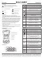
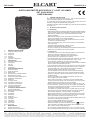
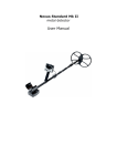
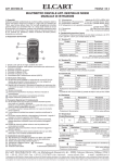
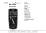
ELCART
ART. 9/9450
Manuale di istruzioni/Scheda tecnica
PAGINA 1 DI 9
MULTIMETRO DIGITALE AUTORANGE CON DISPLAY 3 ½ DIGIT LCD
ART. 9/9450 NI9450
MANUALE DI ISTRUZIONI
1.
ISTRUZIONI GENERALI
Questo strumento rispetta le normative IEC 61010-1, CAT. III 1000V
e CAT.IV 600V.
Per utilizzarlo al meglio, seguite le indicazioni presenti in questo manuale
e rispettate le precauzioni di sicurezza in esso contenute.
I simboli internazionali usati per questo strumento sono spiegate al
capitolo 1.1.3
1.1
1. ISTRUZIONI GENERALI
1.1 Precauzioni di sicurezza
1.1.1 Istruzioni preliminari
1.1.2 Durante l’uso
1.1.3 Simboli
1.1.4 Istruzioni
1.2 Meccanismo di protezione
2. DESCRIZIONE
2.1 Familiarizzare con lo strumento
2.2 Display LCD
2.3 Pulsanti
2.4 Terminali
2.5 Accessori
3. DESCRIZIONE DELLE FUNZIONI
3.1 Funzioni generali
3.1.1 Modalità DATA HOLD
3.1.2 Risparmio batteria
3.2 Funzioni di misura
3.2.1 Misurazioni Tensioni CA e CC
3.2.2 Misurazione Resistenza
3.2.3 Test Diodo
3.2.4 Test Continuità
3.2.5 Misurazione Capacità
3.2.6 Misurazione Transistor
3.2.7 Misurazione Frequenza
3.2.8 Misurazione Temperatura
3.2.9 Misurazione Corrente
4. SPECIFICHE TECNICHE
4.1 Specifiche generali
4.2 Specifiche di misurazione
4.2.1 Tensione CC
4.2.2 Tensione CA
4.2.3 Frequenza
4.2.4 Resistenza
4.2.5 Test Diodi
4.2.6 Test Continuità
4.2.7 Transistor
4.2.8 Temperatura
4.2.9 Capacità
4.2.10 Corrente CC
4.2.11 Corrente CA
5. MANUTENZIONE
5.1 Manutenzione Generale
5.2 Sostituzione Batteria
Precauzioni di sicurezza
1.1.1 Preliminari
* Gli strumenti di categoria IV sono progettati per proteggere l’utilizzatore
dai rischi derivanti dal primo livello di alimentazione (protezione ambientale e di terra).
* La categoria di misurazione III è relativa alle misurazioni effettuate nell’ambito domestico.
* La categoria di misurazione II è relativa alle misurazioni effettuate su
circuiti collegati direttamente a una bassa tensione.
* La categoria di misurazione I è relativa alle misurazioni effettuate su
circuiti non alimentati.
* Quando utilizzate questo multimetro dovete osservare tutte le normali
regole di sicurezza:
- protezione contro il pericolo di scariche elettriche.
- protezione contro usi impropri del multimetro.
* per sicurezza utilizzate i puntali forniti nella confezione.
Prima di utilizzare i puntali, controllate che siano in buone condizioni.
1.1.2 Durante l’uso
* Se utilizzate il multimetro vicino a apparecchi che generano interferenze, controllate che il display non diventi instabile o che indichi errori.
* Non utilizzate il multimetro o i puntali se sembrano danneggiati.
* Utilizzate il multimetro solo per le funzioni specificate in questo manuale
* Prestate attenzione nel caso in cui lavoriate vicino a conduttori non isolati
* Non utilizzate il multimetro vicino a gas esplosivi o polvere
* Verificate periodicamente il funzionamento del multimetro con segnali
conosciuti. Non utilizzatelo se da risultati anormali.
In caso di malfunzionamento contattate un tecnico per la riparazione.
* Nel caso in cui non sappiate quale gamma di misurazione utilizzare,
scegliete la più alta possibile, oppure utilizzate la funzione autorange.
* Per evitare danneggiamenti, non superate il limite massimo di ingresso,
specificato in questo manuale.
* Quando il multimetro è collegato al circuito da misurare, non toccate i
puntali.
* Prestate attenzione quando lavorate con tensioni superiori a 60VCC o
30VCA (Rms).
* Quando procedete alla misurazione collegate prima il puntale nero
(COM) e poi quello rosso (+).
Quando finite la misurazione scollegate prima il puntale rosso e poi
quello nero.
* Prima di cambiare funzione, scollegate i puntali dal circuito.
* Se state effettuando una misurazione CC, prima di passare a una
misurazione in CA, assicuratevi di aver tolto qualsiasi alimentazione per
evitare scosse o guasti allo strumento.
Per tornare a una misurazione CC, selezionate una gamma superiore
all’ultimo valore di CA misurato.
* Togliete l’alimentazione al circuito e scaricate tutti i condensatori prima
di misurare resistenza, continuità, diode e condensatori.
* Non effettuate mai misurazioni di resistenza e continuità su circuiti
alimentati.
* Prima di misurare la corrente, controllate il fusibile del multimetro e
togliete l’alimentazione prima della misurazione.
* Utilizzate una batteria 9V per alimentare lo strumento.
* Sostituite la batteria quando apparirà il simbolo (
).
* Non misurate tensioni superiori a 600V in Categoria IV, o 1000V in
Categoria III.
* Non utilizzate il multimetro senza la custodia
ELCART DISTRIBUTION SPA via Michelangelo Buonarroti, 46 - 20093 Cologno Monzese (Milano) ITALY
Tel. +39 02.25117310 Fax +39 02.25117610 sito internet: www.elcart.com
e-mail: [email protected]
La divulgazione dei dati contenuti in questa scheda è da ritenersi un servizio puramente informativo e non costituisce alcun vincolo da parte della Elcart in merito a prestazioni ed utilizzo del prodotto.
The divulgation of data contained on this technical sheet are exclusively for informational reasons and establish no link on behalf of Elcart regard to thr performances and the usa of the product.
La divulgacion de los datos contenidos en esta ficha son un servicio unicamente informativo y no constituyen ningun vinculo de parte de Elcart respecto a las prestaciones y uso del producto.
ELCART
ART. 9/9450
1.1.3 Simboli:
Attenzione: fate riferimento a questo manuale.
Un uso non corretto potrebbe provocare guasti allo
strumento o ai circuiti da misurare.
~
PAGINA 2 DI 9
Manuale di istruzioni/Scheda tecnica
CA (corrente alternata)
Terra
Fusibile
SIMBOLO
SIGNIFICATO
La batteria è scarica
Per evitari guasti e malfunzionamenti, sostituite la batteria
-
Indicatore letture negative
CC (corrente continua)
AC
Indicatore per tensione e corrente alternata.
Viene visualizzata la media del valore assoluto di ingresso
(valore efficace dell’onda sinusoidale)
Doppio isolamento
DC
~
Modalità Test diodi
Conforme alle
direttive Europee
1.1.4 Istruzioni
* Togliete i puntali prima di aprire il coperchio della batteria.
* In caso di guasti, utilizzate parti di ricambio di stesso livello di qualità.
* Prima di utilizzare lo strumento, scollegate ogni alimentazione dal circuito
da misurare.
* Per qualsiasi manutenzione o riparazione contattate personale qualificato
* Con personale qualificato si intende qualsiasi persona che abbia familiarità con istallazione e costruzione di questo tipo di apparecchiatura.
E’ l’unico personale autorizzato a compiere riparazioni su questi articoli.
* Quando aprite lo strumento ricordate che ci potrebbero essere dei
condensatori carichi che potrebbero danneggiare il circuito interno.
* Se non utilizzate lo strumento a lungo, togliete la batteria e non
conservatelo in luoghi con alta temperatura o umidità.
1.2 Meccanismi di protezione
* Utilizza fusibile (FF400mA/1000V) durante la misurazione di capacità, temperatura, mA e hFE.
* Protezione a PTC permanente fino a 250V durante la misurazione di resistenza, frequenza, continuità e test di diodi.
2. DESCRIZIONE
2.1 Familiarizzare con lo strumento
Indicatore per tensione e corrente continua
Modalità Test continuità
H
Modalità Data Hold
°C, °F
°C: scala Celsius / °F: scala Fahrenheit
V,mV
V: Volts, unità di misura della tensione
mV: Millivolts 1x10⁻³ o 0.001 volts
A,mA,µA
A: Ampere, unità di misura della corrente
mA: Milliampere 1x10⁻³ o 0.001 ampere
µA: Microampere 1x10⁻⁶ o 0.000001 ampere
Ω,KΩ,MΩ
Ω: Ohm, unità di misura della resistenza
KΩ: Kilo ohm 1x10³ o 1000 ohm
MΩ: Mega ohm 1x10⁶ o 1.000.000 ohm
KHz
KHz: Kilohertz 1x10³ o 1000 hertz
F,µF,nF
F: Farad unità di misura della capacità
µF: Micro Farad 1x10⁻⁶ o 0.000001 farad
nF: Nano Farad 1x10⁻⁹ o 0.000000001 farad
2.3 Pulsanti
PULSANTE
OPERAZIONI
Tasto di accensione e spegnimento
FUNC
2.2 Display LCD
1. Area allerta tensione
2. Luce allerta tensione
3. LCD display
4. Pulsanti
H
Tasto “HOLD” per entrare e uscire dalla modalità Hold.
Premendo il tasto per 2", viene attivata la retroilluminazione
MAX/
MIN
Premendolo una volta verrà visualizzato il valore massimo (MAX sul display); premendolo nuovamente verrà
visualizzato il valore minimo (MIN sul display).
Mantenendolo premuto per più di 2", il multimetro
tornerà alla funzione normale.
Durante la visualizzazione, il multimetro continuerà
con la misura e i due valori verranno aggiornati
RANGE
Consente di scegliere la modalità manuale o autorange.
La modalità di default è autorange.
Premendo il tasto per più di 2", cambierete la modalità
di misurazione. Nella modalità manuale, premendo il
tasto potrete cambiare la gamma di misurazione.
REL
Premendo il tasto “REL” memorizzerete il valore da
cui partire per la misurazione relativa.
Il valore che visualizzerete successivamente, sarà
relativo a quello memorizzato e non allo 0.
Pertanto il valore sarà dato da: Vx-Vref = V display
Hz/Duty
Premendo il tasto “Hz/Duty” potrete selezionare le
funzioni Frequenza e duty cicle.
COM
Terminale di ritorno per ogni misurazione (COM o massa)
5. Manopola
6. Terminali
Tasto “FUNC” per selezionare le diverse funzioni.
CC/CA, resistenza/continuità/diodi/capacità e °C/°F.
Ingresso per misurazione di tensione, resistenza,
capacità, frequenza, diodi e continuità
MAX/
MIN
Ingresso per misurazione di capacità, temperatura,
hFE e corrente mA
10 A
Ingresso per misurazione di corrente da 400mA a 10A
(Inserire puntale rosso)
ELCART DISTRIBUTION SPA via Michelangelo Buonarroti, 46 - 20093 Cologno Monzese (Milano) ITALY
Tel. +39 02.25117310 Fax +39 02.25117610 sito internet: www.elcart.com
e-mail: [email protected]
La divulgazione dei dati contenuti in questa scheda è da ritenersi un servizio puramente informativo e non costituisce alcun vincolo da parte della Elcart in merito a prestazioni ed utilizzo del prodotto.
The divulgation of data contained on this technical sheet are exclusively for informational reasons and establish no link on behalf of Elcart regard to thr performances and the usa of the product.
La divulgacion de los datos contenidos en esta ficha son un servicio unicamente informativo y no constituyen ningun vinculo de parte de Elcart respecto a las prestaciones y uso del producto.
ELCART
ART. 9/9450
PAGINA 3 DI 9
Manuale di istruzioni/Scheda tecnica
3.2.9 Misurazione Corrente
4.2 Specifiche di misurazione
La precisione dello strumento è valida fino a un anno dopo la calibrazione,
a una temperatura di lavoro compresa tra i 18°C e i 28°C con umidità
relativa compresa tra 0% e 75%.
ATTENZIONE
Per evitare danneggiamenti dello strumento non tentate di
4.2.1 Tensione VCC
effettuare misurazioni su circuiti con potenziale
RANGE
RISOLUZIONE
PRECISIONE
Prima di effettuare misurazioni controllate l’integrità
200mV
0.1mV
±(0.5% of rdg+1digits)
del fusibile dello strumento.
2V
1mV
±(0.5% of rdg+1digits)
di circuito aperto superiore a 250V.
Utilizzate la giusta gamma di misurazione, non collegate
20V
10mV
±(0.5% of rdg+1digits)
mai i puntali in parallelo a un componente quando siete
200V
100mV
±(0.5% of rdg+1digits)
nella funzione di misurazione di corrente.
1000V
1V
±(0.8% of rdg+2digits)
Gamme di misurazione:
CC: 200mA, 10A
CA: 200mA, 10A
Per misurazioni di corrente:
Impedenza di ingresso: 10MΩ
Max tensione di ingresso: 250Vcc/Vca rms per la gamma 200mV 1000Vcc o 750Vca rms per le altre gamme
4.2.2 Tensione VCA
1 Togliete l’alimentazione al circuito da misurare e scaricate tutti i
RANGE
condensatori
RISOLUZIONE
PRECISIONE
2.Ruotate la manopola sulla gamma di misurazione desiderata
2V
1mV
±(0.8% of rdg+3digits)
3.Collegate il puntale nero al terminale COM e quello rosso al terminale 20V
10mV
±(0.8% of rdg+3digits)
mA (per misurazioni fino a 200mA).
200V
100mV
±(0.8% of rdg+3digits)
Per misurazioni fino a 10A, utilizzate il terminale 10A
750V
1V
±(1.2% of rdg+3digits)
4.Collegate il multimetro in serie al circuito
5.Accendete l’alimentazione del circuito e sul display vi verrà visualizzato il valore misurato
Se sul display sarà visualizzato il simbolo “1”, significherà che dovete selezionare una gamma di misurazione più alta
6.Spegnete l’alimentazione, scaricate i condensatori e poi rimuovete i puntali
4 SPECIFICHE TECNICHE
4.1 SPECIFICHE GENERALI
- Condizioni ambientali: 10Ω
±(0.8% of rdg+1digits)
100Ω
±(0.8% of rdg+1digits)
200MΩ
0.1MΩ
±(5.0% of rdg+10digits)
-10°C÷+60°C, 14°F÷140°F
(<70% RH, rimuovere la batteria)
0.1%(precisione specificata)/°C
Protezione sovraccarico: Tensione circuito aperto: RANGE
RISOLUZIONE
FUNZIONE
1mV
Il Display visualizzerà la tensione di
caduta del diodo.
750VCA rms o 1000VCC
mA: fusibile (FF400mA/1000V)
A: fusibile (FF10A/500V)
3 1/2" digits LCD
con indicazione automatica di funzioni e simboli
- Indicatore batteria scarica: LCD visualizzerà "1"
simbolo "
" visualizzato sul display
"-" visualizzato automaticamente
9V
NEDA 1604, 6F22, or 006P
188(L)x92(W)x50(H) mm
380gr. circa (batteria inclusa)
250Vcc o 250Vca rms
<700mV
4.2.4 Diodi
(<18°C o >28°C)
- Indicazione sovraccarico: - Peso: 20KΩ
200KΩ
±(1.0% of rdg+2digits)
- Display: - Dimensioni: ±(0.8% of rdg+1digits)
< 2000m
- Tipo Batteria: ±(0.8% of rdg+3digits)
1Ω
±(0.8% of rdg+1digits)
(<80% RH, <10°C senza condensa)
- Protezione fusibile: - Alimentazione: 0.1Ω
2KΩ
1KΩ
- Indicazione polarità: 200Ω
10KΩ
0°C÷40°C, 32°F÷122°F
- MAX tensione tra terminali e massa:
PRECISIONE
2MΩ
- Temperatura di conservazione: RISOLUZIONE
20MΩ
- Temperatura di utilizzo: - Coefficiente di temperatura:
RANGE
2
- Altitudine di utilizzo: 4.2.3 Resistenza
1000V CAT. II e 600V CAT. III
- Grado di inquinamento: Impedenza di ingresso: 10MΩ
Max tensione di ingresso: 250Vcc/Vca rms per la gamma 200mV 1000Vcc o 750Vca rms per le altre gamme
Gamma di Frequenza: 40Hz-400Hz
Risposta: media, calibrazione in valore efficace di un’onda sinusoidale
Tensione di caduta CC: Tensione di caduta inversa CC: Protezione sovraccarico: circa 1mA
circa 2.8V
250Vcc o 250Vca rms
4.2.5 Continuità
RANGE
FUNZIONE
Se viene misurata una resistenza ≤30Ω il buzzer suonerà
Corrente di test: Tensione di caduta inversa CC: Protezione sovraccarico: circa 1mA
circa 2.8V
250Vcc o 250Vca rms
ELCART DISTRIBUTION SPA via Michelangelo Buonarroti, 46 - 20093 Cologno Monzese (Milano) ITALY
Tel. +39 02.25117310 Fax +39 02.25117610 sito internet: www.elcart.com
e-mail: [email protected]
La divulgazione dei dati contenuti in questa scheda è da ritenersi un servizio puramente informativo e non costituisce alcun vincolo da parte della Elcart in merito a prestazioni ed utilizzo del prodotto.
The divulgation of data contained on this technical sheet are exclusively for informational reasons and establish no link on behalf of Elcart regard to thr performances and the usa of the product.
La divulgacion de los datos contenidos en esta ficha son un servicio unicamente informativo y no constituyen ningun vinculo de parte de Elcart respecto a las prestaciones y uso del producto.
ELCART
ART. 9/9450
PAGINA 4 DI 9
Manuale di istruzioni/Scheda tecnica
4.2.6 Transistor
RANGE
DESCRIZIONE
CONDIZIONI DEL TEST
hFE
Il valore approssimativo Hfe
(0÷1000) del transistor verrà
visualizzato sul display
Corrente di base
approssimativa 10μA,
Vce approssimativa 2.8V
4.2.7 Induttanza
RANGE
RISOLUZIONE
PRECISIONE
20mH
0.01mH
±(3.0% of rdg+5digits)
200mH
0.1mH
±(3.0% of rdg+5digits)
2H
1mH
±(3.0% of rdg+5digits)
20H
10mH
±(3.0% of rdg+5digits)
Protezione sovraccarico: fusibile (FF400mA/1000V)
5. MANUTENZIONE
Non tentate di riparare lo strumento. Solo persone qualificate possono
effettuare riparazioni tecniche sul multimetro.
5.1 Manutenzione generale
ATTENZIONE
Per evitare danneggiamenti, non utilizzate getti d’acqua vicino allo
strumento. Rimuovete i puntali e qualsiasi segnale di ingresso
prima di aprire lo strumento.
Periodicamente strofinate lo strumento con un panno umido e un detergente
delicato, non utilizzate panni abrasivi o solventi.
Sporcizia e umidità possono provocare errate misurazioni.
Per pulire i terminali:
- Spegnete lo strumento e rimuovete i puntali
- Scuotetelo per far uscire lo sporco dai terminali
- Impregnate un tampone con un detergente per pulizia
- Utilizzate il tampone intorno a ogni terminale. Il detergente creerà una
patina di protezione contro le contaminazioni da umidità.
5.2 Sostituzione Batteria e fusibile
ATTENZIONE
4.2.8 Capacità
RANGE
RISOLUZIONE
PRECISIONE
20nF
10pF
±(4.0% of rdg+3digits)
200nF
0.1nF
±(4.0% of rdg+3digits)
2µF
1nF
±(4.0% of rdg+3digits)
200µF
100nF
±(5.0% of rdg+10digits)
Protezione sovraccarico: fusibile (FF400mA/1000V)
4.2.9 Corrente CC
RANGE
RISOLUZIONE
PRECISIONE
200mA
0.1mA
±(1.5% of rdg+1digits)
10A
10mA
±(2.0% of rdg+5digits)
Protezione sovraccarico: Per evitare errori di lettura, scosse elettriche o guasti,
sostituite la batteria appena verrà visualizzato il simbolo.
Utilizzate fusibili di ricambio identici a quello in dotazione.
FF400mA/1000V Min interrupt rating 10000A
FF10A/500V Min interrupt rating 10000A
Per sostituire la batteria o il fusibile:
- Spegnete lo strumento
- Scollegate ogni puntali o qualsiasi connettore collegato al multimetro
- Con un cacciavite, svitate le due viti che chiudono il coperchio della batteria
- Togliete il coperchio dallo strumento
- Rimuovete la batteria esaurita o il fusibile danneggiato
- Sostituite la batteria o il fusibile
- Richiudete il coperchio e fissatelo con le due viti al multimetro
fusibile (FF400mA/1000V)
gamma 10A fusibile(FF10A/500V)
Max corrente di ingresso: 200mA CC o 200mA CA rms per gamma mA 10A CC o 10A CA rms per gamma 10A
Per misurazioni >5A: 10 secondi max di durata, 1 minuto di stop;
sopra 10A non specificato
Informazioni agli utenti
4.2.10 Corrente CA
RANGE
RISOLUZIONE
PRECISIONE
200mA
0.1mA
±(1.8% of rdg+3digits)
10A
10mA
±(3.0% of rdg+7digits)
Protezione sovraccarico: fusibile (FF400mA/1000V)
gamma 10A fusibile(FF10A/500V)
Max corrente di ingresso: 200mA CC o 200mA CA rms per gamma mA Per misurazioni >5A: Gamma di Frequenza: Il simbolo riportato sull’apparecchiatura indica che il rifiuto deve essere oggetto di
“raccolta separata”.
Pertanto, l’utente dovrà conferire (o far conferire) il rifiuto ai centri di raccolta differenziata
predisposti dalle amministrazioni comunali, oppure consegnarlo al rivenditore contro
acquisto di una nuova apparecchiatura di tipo equivalente.
La raccolta differenziata del rifiuto e le successive operazioni di trattamento, recupero
e smaltimento favoriscono la produzione di apparecchiature con materiali riciclati e
limitano gli effetti negativi sull’ambiente e sulla salute eventualmente causati da una
gestione impropria del rifiuto.
Lo smaltimento abusivo del prodotto da parte dell’utente comporta l’applicazione delle
sanzioni amministrative di cui l’articolo 50 e seguenti del D. Lgs. N° 22/1997.
10A CC o 10A CA rms per gamma 10A
10 secondi max di durata, 1 minuto di stop;
sopra 10A non specificato
40Hz-400Hz
Risposta: media, calibrazione in valore efficace di un’onda sinusoidale
IMPORTATO E DISTRIBUITO DA
ELCART DISTRIBUTION SPA
Via Michelangelo Buonarroti, 46
20093 COLOGNO MONZESE (MI)
ITALY
www.elcart.com - [email protected] Made in China
ELCART DISTRIBUTION SPA via Michelangelo Buonarroti, 46 - 20093 Cologno Monzese (Milano) ITALY
Tel. +39 02.25117310 Fax +39 02.25117610 sito internet: www.elcart.com
e-mail: [email protected]
La divulgazione dei dati contenuti in questa scheda è da ritenersi un servizio puramente informativo e non costituisce alcun vincolo da parte della Elcart in merito a prestazioni ed utilizzo del prodotto.
The divulgation of data contained on this technical sheet are exclusively for informational reasons and establish no link on behalf of Elcart regard to thr performances and the usa of the product.
La divulgacion de los datos contenidos en esta ficha son un servicio unicamente informativo y no constituyen ningun vinculo de parte de Elcart respecto a las prestaciones y uso del producto.
ELCART
ART. 9/9450
Manuale di istruzioni/Scheda tecnica
PAGINA 5 DI 9
DIGITAL MULTIMETER WITH DISPLAY 3 ½ DIGIT LCD NIMEX
ART. 9/9420 NI 9420
USER'S MANUAL
1. GENERAL INSTRUCTIONS
This instrument complies with IEC 61010-1, CAT. III 1000V and CAT. IV
600V overvoltage standards. See Specifications.
To get the best service from this instrument, read carefully this user's
manual and respect the detailed safety precautions.
International symbols used on the Meter and in this manual are explained
in chapter 1.1.3
1.1 Precautions safety measures
1. GENERAL INSTRUCTIONS
1.1 Precaution safety measures
1.1.1 Preliminary
1.1.2 During use
1.1.3 Symbols
1.1.4 Instructions
1.2 Protection mechanisms
2. DESCRIPTION
2.1 Instrument Familiarization
2.2 LCD Display
2.3 Key pad
2.4 Terminals
2.5 Accessories
3. FUNCTION DESCRIPTION
3.1 General Functions
3.1.1 DATA HOLD mode
3.1.2 Battery saver
3.1.3 Non-Contact AC Voltage detection
3.2 Measurement Functions
3.2.1 AC and DC Voltage measurement
3.2.2 Resistance measurement
3.2.3 Diode Test
3.2.4 Continuity Check
3.2.5 Capacitance measurement
3.2.6 Inductance measurement
3.2.7 Transistor measurement
3.2.8 Current measurement
4. TECHNICAL SPECIFICATIONS
4.1 General specifications..
4.2 Measurement specifications
4.2.1 DC Voltage
4.2.2 AC Voltage
4.2.3 Resistance
4.2.4 Diode Test
4.2.5 Continuity Check
4.2.6 Transistor
4.2.7 Inductance
4.2.8 Capacitance
4.2.9 DC Current
4.2.10 AC Current
5. MAINTENANCE
5.1 General maintenance
5.2 Battery and Fuse replacement
1.1.1 Preliminary
* Measurement category IV meters are designed to protect against transients from the primary supply level (overhead or underground utility service).
* Measurement category III is for measurements performed in the
building installation.
* Measurement category II is for measurements performed on circuits directly connected to the low voltage installation.
* Measurement category I is for measurements performed on circuits not directly connected to MAINS.
* When using this Multimeter, the user must observe all normal safety rules concerning:
- protection against the dangers of electric current
- protection of the Multimeter against misuse
* For your own safety, only use the test probes supplied with the instrument Before use, check that they are in good condition
1.1.2 During use
* If the meter is used near noise generating equipment, be aware that display may become unstable or indicate large errors.
* Do not use the meter or test leads if they look damaged.
* Use the meter only as specified in this manual;
* Use extreme caution when working around bare conductors or bus bars
* Do not operate the meter around explosive gas, vapor, or dust.
* Verify a Meter's operation by measuring a known voltage.
Do not use the Meter if it operates abnormally, protection may be impaired
When in doubt, have the Meter serviced.
* Uses the proper terminals, function, and range for your measurements
* When the range of the value to be measured is unknown, check that the range initially set on the multimeter is the highest possible or, wherever possible, choose the auto-ranging mode.
* To avoid damages to the instrument, do not exceed the maximum limits of the input values shown in the technical specification tables.
* When the multimeter is linked to measurement circuits, do not touch unused terminals.
* Caution when working with voltages above 60Vdc or 30Vac rms.
Such voltages pose a shock hazard.
* When making connections, connect the common test lead before connecting the live test lead; when disconnecting, disconnect the live test lead before disconnecting the common test lead.
* Before changing functions, disconnect the test leads from the circuit.
* For all dc functions, including manual or auto-ranging, to avoid the risk of shock due to possible improper reading, verify the presence of any ac voltages by first using the ac function.
Then select a dc voltage range equal to or greater than the ac range.
* Disconnect circuits power and discharge all high-voltage capacitors before testing resistance, continuity, diodes, or capacitance.
* Never perform resistance or continuity measurements on live circuits.
* Before measuring current, check the meter's fuse and turn off power to the circuit before connecting the meter to the circuit.
* In TV repair work, remember that high amplitude voltage pulses at the test points can damage the multimeter.
Use of a TV filter will attenuate any such pulses.
* Use the 9V NEDA battery to power the Meter.
* Replace the battery as soon as the battery indicator (
) appears.
With a low battery, the Meter might produce false readings that can lead to electric shock and personal injury.
* Do not measure voltages above 600V in Cat. IV, or 1000V in Cat. III.
* Do not operate the Meter with the case (or part of the case) removed.
ELCART DISTRIBUTION SPA via Michelangelo Buonarroti, 46 - 20093 Cologno Monzese (Milano) ITALY
Tel. +39 02.25117310 Fax +39 02.25117610 sito internet: www.elcart.com
e-mail: [email protected]
La divulgazione dei dati contenuti in questa scheda è da ritenersi un servizio puramente informativo e non costituisce alcun vincolo da parte della Elcart in merito a prestazioni ed utilizzo del prodotto.
The divulgation of data contained on this technical sheet are exclusively for informational reasons and establish no link on behalf of Elcart regard to thr performances and the usa of the product.
La divulgacion de los datos contenidos en esta ficha son un servicio unicamente informativo y no constituyen ningun vinculo de parte de Elcart respecto a las prestaciones y uso del producto.
ELCART
ART. 9/9450
1.1.3 Symbols:
~
PAGINA 6 DI 9
Manuale di istruzioni/Scheda tecnica
Caution: refer to the instruction manual.
Incorrect use may result in damage to the device
or its components
AC (Alternating Current)
DC (Direct Current)
Earth ground
Double insulated
Fuse
Conforms to European Union directives
1.1.4 Instructions
* Remove test leads from the Meter before opening the battery cover.
* When servicing the Meter, use only specified replacement parts.
* Before opening up the instrument, always disconnect from all sources of electric current and make sure you are not charged with static electricity
* Any adjustment, maintenance or repair work carried out on the meter while it is live should be carried out only by appropriately qualified personnel, after having taken into account the instructions in this present manual.
* A "qualified person" is someone who is familiar with the installation, construction and operation of the equipment and the hazards involved. He is trained and authorized to energize and de-energize circuits and equipment in accordance with established practices.
* When the instrument is opened up, remember that some internal capacitors can retain a dangerous potential even after the instrument is switched off.
* If any faults or abnormalities are observed, take the instrument out of service and ensure that it cannot be used until it has been checked out.
* If the meter is not going to be used for a long time, take out the battery and do not store the meter in high temperature or high humidity environment.
1.2 Protection mechanisms
* Fused by the fuse (FF400mA/1000V) during capacitance,temperature, mA and hFE measurements.
* A PTC resistor protects against permanent over-voltages of up to 250V during resistance, frequency, continuity and diode test measurements.
2. DESCRIPTION
2.1 Instrument Familiarization
SYMBOL
MEANING
The battery is low
Warning:
To avoid false readings and malfunction, replace the
battery as soon as the battery indicator appears.
-
Indicates negative readings
AC
Indicator for ac voltage or current.
AC voltage and current are displayed as the average of
the absolute value of the input, calibrated to indicate the
equivalent rms value of a sine wave.
~
DC
Indicator for dc voltage or current
The Meter is in the Diode Test mode
The Meter is in the Continuity Check mode
H
The Meter is in the Data Hold mode
mH / H
H: Henry, the unit of inductance
mH: Milli Henry 1x10⁻³ or 0.001 henry
V,mV
V: Volts, the unit of voltage
mV: milliVolts 1x10⁻³ or 0.001 volts
A,mA,µA
A: Amperes (amps), the unit of current
mA: Milliampere 1x10⁻³ or 0.001 amperes
µA: Microampere 1x10⁻⁶ or 0.000001 amperes
Ω,KΩ,MΩ
Ω: Ohm, the unit of resistance
KΩ: Kilo ohm 1x10³ or 1000 ohms
MΩ: Mega ohm 1x10⁶ or 1.000.000 ohms
KHz
KHz: Kilohertz 1x10³ or 1000 hertz
F,µF,nF
F: Farad, the unit of capacitance
µF: Micro Farad 1x10⁻⁶ or 0.000001 farad
nF: Nano Farad 1x10⁻⁹ or 0.000000001 farad
2.3 Keypad
KEY
2.2 Display LCD
Operation performed
1. Voltage alert area
2. Voltage alert light
turn the meter ON or OFF
HOLD
Press to turn the backlight on.
After about 5 seconds, the backlight is auto-off.
3. LCD display
4. Keypad
5. Rotary switch
6. Terminals
Press HOLD to enter and exit the Data Hold mode
2.4 Terminals
Terminal
DESCRIPTION
COM
Return terminal for all measurements.
(Receiving the black test lead or the “COM” plug)
V/Ω
Input for voltage, resistance, diode
and continuity measurements
hFE/mA/Lx
Input for capacitance, Inductance, hFE and mA
current measurements
10A
Input for 200mA to 10A current measurements
2.5 Accessories
Delivered with the multimeter:
* User's manual
* Test leads
* Carry case
* Special Multi-function socket
ELCART DISTRIBUTION SPA via Michelangelo Buonarroti, 46 - 20093 Cologno Monzese (Milano) ITALY
Tel. +39 02.25117310 Fax +39 02.25117610 sito internet: www.elcart.com
e-mail: [email protected]
La divulgazione dei dati contenuti in questa scheda è da ritenersi un servizio puramente informativo e non costituisce alcun vincolo da parte della Elcart in merito a prestazioni ed utilizzo del prodotto.
The divulgation of data contained on this technical sheet are exclusively for informational reasons and establish no link on behalf of Elcart regard to thr performances and the usa of the product.
La divulgacion de los datos contenidos en esta ficha son un servicio unicamente informativo y no constituyen ningun vinculo de parte de Elcart respecto a las prestaciones y uso del producto.
ELCART
ART. 9/9450
PAGINA 7 DI 9
Manuale di istruzioni/Scheda tecnica
3. FUNCTION DESCRIPTION
3.1 General Functions
3.1.1 DATA HOLD mode
Data Hold mode makes the meter stop updating the display.
Data Hold function can be cancelled by changing the measurement
mode, or push HOLD key again.
To enter and exit the Data Hold mode:
1. Press HOLD key, fixes the display on the current value, H is displayed
2. A second short press returns the meter to normal mode.
3.1.2 Battery Saver
The meter will be turned OFF automatic after approx 15 minutes
3.1.3 Non Contact AC Voltage detection
Hold the Meter so that the Meter’s top is vertically and horizontally centered and contacting the conductor, when the live voltage >110V(RMS),
the sensing indicator will be on.
Note:
1. Even without LED indication, the voltage may still exist.
Do not rely on non-contact voltage detector to determine the presence
of voltage wire; detection operation may be subject to socket design,
insulation thickness and different type and other factors.
2. When the meter input terminals presence voltage, due to the influence
of presenced voltage, voltage sensing indicator may also be bright.
3. Keep the meter away from electrical noise sources during the tests,
i.e., fluorescent lights, dimmable lights, motors, etc..
These sources can trigger NON-Contact AC Voltage Detection Function
and invalidate the test.
3.2 Measurement Functions
3.2.1 AC and DC Voltage measurement
WARNING
To test a diode out of a circuit:
1. Set the rotary switch to
range.
2. Connect the black test lead to the COM and red to the
terminals 3. For forward-bias readings on any semiconductor component, place the red test lead on the component's anode and place the black test lead on the component's cathode.
4. The meter will show the approx. forward voltage of the diode.
If the test lead connection is reversed, only figure "1" displayed.
3.2.4 Continuity Check
WARNING
To avoid electrical shock and/or damage to the instrument,
disconnect circuit power and discharge
all high-voltage capacitors before testing for continuity.
Continuity is a complete path for current flow, the beeper sounds if a circuit
is complete. These brief contacts cause the meter to emit a short beep.
To test for continuity:
1. Set the rotary switch to
range.
2. Press the yellow key twice to activate Continuity Check.
3. Connect the black test lead to the COM and red to the Ω terminals
4. Connect the test leads to the resistance in the circuit being measured
5. When the test lead to the circuit is below approx. 30Ω, a continuous beeping will indicate it.
Note:
- Continuity test is available to check open/short of the circuit.
3.2.5 Capacitance measurement
WARNING
To avoid electrical shock and/or damage to the instrument,
do not attempt to take any voltage measurement
that might exceeds 1000Vdc or 750Vac rms.
To avoid electrical shock and/or damage to the instrument,
disconnect circuit power and discharge all high-voltage capacitors
before measuring capacitance. Use the DC voltage function
to confirm that the capacitor is discharged.
The polarity of AC (alternating current) voltage varies over time;
the polarity of DC (direct current) voltage is constant.
DC voltage ranges are: 200mV, 2V, 20V, 200V, 1000V
AC voltage ranges are: 2V, 20V, 200V, 7500V
To measure AC or DC voltage:
1. Set rotary switch to the proper range.
2. Connect the black test lead to the COM and red to the V terminals 3. Connect the test leads to the circuit being measured
4. Read the displayed value.
The polarity of red test lead connection will be indicated when making a
DCV measurement.
Capacitance ranges are: 20nF, 200nF, 2µF, 200µF
To measure capacitance:
1. Set the rotary switch to proper range.
2. Connect the black test lead to the COM and red to the
terminals
3. Connect the test leads to the capacitor being measured
4. Read the displayed value
Note:
* The meter may take a few seconds to stabilize reading.
This is normal for high capacitance measuring.
* To improve the accuracy of measurements less than 20nF, subtract the residual capacitance of the Meter and leads
3.2.2 Resistance measurement
WARNING
To avoid electrical shock and/or damage to the instrument,
disconnect circuit power and discharge
all high-voltage capacitors before measuring resistance.
Resistance ranges are: 200Ω, 2kΩ, 20kΩ, 200kΩ, 2MΩ, 20MΩ, 200MΩ
To measure resistance:
1. Set the rotary switch to proper range.
2. Connect the black test lead to the COM and red to the V terminals
3. Connect the test leads to the circuit being measured and read the displayed value.
NOTE:
On 20MΩ and 200MΩ ranges, the meter may take a few seconds to
stabilize reading; this is normal for high resistance measuring.
3.2.3 Diode Test
WARNING
To avoid electrical shock and/or damage to the instrument,
disconnect circuit power and discharge
all high-voltage capacitors before testing diodes.
Use the diode test to check diodes, and other semi-conductor devices.
The diode test sends a current through the semiconductor junction, and
then measures the voltage drop across the junction; a good silicon junction
drops between 0.5V and 0.8V.
3.2.6 Inductance measurement
The unit of inductance is the Henry (H)
Inductance ranges are: 20mH, 200mH, 2H, 200H
To measure inductance:
1. Set the rotary switch to proper range.
2. Connect the black test lead to the COM and red to the LX terminals
3. Connect the test leads to the inductance being measured
4. Read the displayed value
3.2.7 Transistor measurement
WARNING
To avoid electrical shock and/or damage to the instrument,
do not apply more than 250Vdc or 250Vac rms between the hFE
terminal and the COM terminal.
1. Set the rotary switch to hFE range.
2. Connect the “com” plug and “+” plug of the special multi-function socket to the COM and hFE terminals.
3. Determine whether the transistor to be tested is NPN or PNP type and locate the Emitter, Base and Collector leads.
4. Insert leads of the transistor into proper holes of the special
multi-function socket.
5. The meter will show the approx. hFE value at test condition of base current 10μA and Vce 2.8V.
ELCART DISTRIBUTION SPA via Michelangelo Buonarroti, 46 - 20093 Cologno Monzese (Milano) ITALY
Tel. +39 02.25117310 Fax +39 02.25117610 sito internet: www.elcart.com
e-mail: [email protected]
La divulgazione dei dati contenuti in questa scheda è da ritenersi un servizio puramente informativo e non costituisce alcun vincolo da parte della Elcart in merito a prestazioni ed utilizzo del prodotto.
The divulgation of data contained on this technical sheet are exclusively for informational reasons and establish no link on behalf of Elcart regard to thr performances and the usa of the product.
La divulgacion de los datos contenidos en esta ficha son un servicio unicamente informativo y no constituyen ningun vinculo de parte de Elcart respecto a las prestaciones y uso del producto.
ELCART
ART. 9/9450
4.2 Measurement specifications
3.2.8 Current measurement
WARNING
To avoid damage to the Meter or injury if the fuse blows, never
attempt an in-circuit current measurement where the open-circuit
potential to earth is greater than 250V.
before proceeding.
Use the proper terminals, function, and range for your measurement.
Never place the test leads in parallel with a circuit or component
when the leads are plugged into the current terminals.
DC current ranges are:
DC: 200mA, 10A
AC: 200mA, 10A
To measure current:
1. Turn off the power of the measured circuit.
Discharge all the high voltage capacitors.
3. Connect the black test lead to the COM terminal and the red to the mA terminal for a maximum of 200mA.
For a maximum of 10A, move the red test lead to the 10A terminal.
4. Break the circuit path to be tested.
Connect the black test lead to the more negative side of the break; connect the red test lead to the more positive side of the break.
(Reversing the leads will give a negative reading,but will not damage the Meter)
5. Turn on the power of the measured circuit, and then read the display. Be sure to note the measurement units at the right side of the display (mA or A). When only the figure "1" displayed, it indicates overrange situation and the higher range has to be selected.
6. Turn off the power of the measured circuit and discharge all the high voltage capacitors.
Remove the test leads and recover the measured circuit.
4 TECHNICAL SPECIFICATIONS
4.1 GENERAL SPECIFICATIONS
1000V CAT. II e 600V CAT. III
- Pollution degree: 2
- Operating altitude: < 2000m
- Operating temperature: 0°C÷40°C, 32°F÷122°F
(<80% RH, <10°C non condensing)
- Storage temperature: -10°C÷+60°C, 14°F÷140°F
RANGE
RESOLUTION
ACCURACY
200mV
0.1mV
±(0.5% of rdg+1digits)
2V
1mV
±(0.5% of rdg+1digits)
20V
10mV
±(0.5% of rdg+1digits)
200V
100mV
±(0.5% of rdg+1digits)
1000V
1V
±(0.8% of rdg+2digits)
Input impedance: Max input voltage: (<70% RH, battery removed)
- Temperature coefficient:0.1% (specified accuracy)/°C (<18°C o >28°C)
RANGE
RESOLUTION
ACCURACY
2V
1mV
±(0.8% of rdg+3digits)
20V
10mV
±(0.8% of rdg+3digits)
200V
100mV
±(0.8% of rdg+3digits)
750V
1V
±(1.2% of rdg+3digits)
Input impedance: Max. input voltage: Frequency Range: Response: 750VCA rms o 1000VCC
- Fuse Protection: mA: fuse (FF400mA/1000V) / A: fuse (FF10A/500V)
- Display:3 1/2" digits LCD automatic indication of functions and symbols
- Over Range indication: - Polarity indication: - Power source: LCD will display "1".
the "
" is displayed when the battery is under the proper operation range
"-" displayed automatically
9V
- Battery type: NEDA 1604, 6F22, or 006P
- Dimensions: 188(L)x92(W)x50(H) mm
- Weight: 380g. approx (battery included)
10MΩ
250Vdc or ac rms for 200mV range
and 1000Vdc or 750V ac rms for other ranges
40Hz-400Hz
Average, calibrated in rms of sine wave
4.2.3 Resistance
RANGE
RESOLUTION
ACCURACY
200Ω
0.1Ω
±(0.8% of rdg+3digits)
2KΩ
1Ω
±(0.8% of rdg+1digits)
20KΩ
10Ω
±(0.8% of rdg+1digits)
200KΩ
100Ω
±(0.8% of rdg+1digits)
2MΩ
1KΩ
±(0.8% of rdg+1digits)
20MΩ
10KΩ
±(1.0% of rdg+2digits)
200MΩ
0.1MΩ
±(5.0% of rdg+10digits)
Overload protection: Open Circuit Voltage: 250V dc or 250Vac rms
less than 700mV
4.2.4 Diode
RANGE
- MAX voltage between terminals and earth ground:
10MΩ
250Vdc or ac rms for 200mV range
and 1000Vdc or 750V ac rms for other ranges
4.2.2 AC Voltage
2. Set the rotary switch to the proper range.
- Environment conditions: Accuracy is specified for one year after calibration, at operating temperatures of 18°C to 28°C, with relative humidity at 0% to 75%.
Accuracy specifications take the form of:
±(% of Reading + Number of Least Significant Digits)
4.2.1 DC Voltage
To avoid damage to the meter, check the meter's fuse
- Low battery indication: PAGINA 8 DI 9
Manuale di istruzioni/Scheda tecnica
RESOLUTION
ACCURACY
1mV
Display read approx. forward voltage
of diode
Forward DC Current: Reversed DC Voltage: Overload protection: approx. 1mA
approx. 2.8V
250Vdc or 250Vac rms
4.2.5 Audible continuity
RANGE
FUNCTION
The buzzer sound if the resistance of a circuit
under test is less than 30Ω
Test Current: Reversed DC Voltage: Overload protection: approx. 1mA
approx. 2.8V
250Vdc or 250Vac rms
ELCART DISTRIBUTION SPA via Michelangelo Buonarroti, 46 - 20093 Cologno Monzese (Milano) ITALY
Tel. +39 02.25117310 Fax +39 02.25117610 sito internet: www.elcart.com
e-mail: [email protected]
La divulgazione dei dati contenuti in questa scheda è da ritenersi un servizio puramente informativo e non costituisce alcun vincolo da parte della Elcart in merito a prestazioni ed utilizzo del prodotto.
The divulgation of data contained on this technical sheet are exclusively for informational reasons and establish no link on behalf of Elcart regard to thr performances and the usa of the product.
La divulgacion de los datos contenidos en esta ficha son un servicio unicamente informativo y no constituyen ningun vinculo de parte de Elcart respecto a las prestaciones y uso del producto.
ELCART
ART. 9/9450
PAGINA 9 DI 9
Manuale di istruzioni/Scheda tecnica
5. MAINTENANCE
4.2.6 Transistor
RANGE
Description
TEST CONDITION
hFE
Display read approx. HFE value
(0-1000) of transistor under test
(all type)
Base Current approx.
10μA, Vce approx. 2.8V
Do not attempt to repair or service your Meter unless you are qualified
to do so and have the relevant calibration, performance test, and service
information.
5.1 General Maintenance
WARNING
4.2.7 Inductance
RANGE
RISOLUZIONE
PRECISIONE
20mH
0.01mH
±(3.0% of rdg+5digits)
200mH
0.1mH
±(3.0% of rdg+5digits)
2H
1mH
±(3.0% of rdg+5digits)
20H
10mH
±(3.0% of rdg+5digits)
Overload protection: fuse (FF400mA/1000V)
4.2.8 Capacitance
RANGE
RESOLUTION
ACCURACY
20nF
10pF
±(4.0% of rdg+3digits)
200nF
0.1nF
±(4.0% of rdg+3digits)
2µF
1nF
±(4.0% of rdg+3digits)
200µF
100nF
±(5.0% of rdg+10digits)
Overload protection: fuse (FF400mA/1000V)
4.2.9 DC Current
RANGE
RESOLUTION
ACCURACY
200mA
0.1mA
±(1.5% of rdg+1digits)
10A
10mA
±(2.0% of rdg+5digits)
Overload protection: fuse (FF400mA/1000V)
10A range fuse(FF10A/500V)
Max. input current: 200mA dc or 200mA ac rms for mA range
To avoid electrical shock or damage to the meter,
do not get water inside the case.
Remove the test leads and any input signals before
opening the case
Periodically wipe the case with a damp cloth and mild detergent.
Do not use abrasives or solvents.
Dirt or moisture in the terminals can affect readings.
To clean the terminals:
- Turn the meter off and remove all test leads.
- Shake out any dirt that may be in the terminals.
- Soak a new swab with a cleaning and oiling agent (such as WD-40).
- Work the swab around in each terminal. The oiling agent insulates the
terminals from moisture-related contamination.
5.2 Battery and Fuse replacement
WARNING
To avoid false readings, which could lead to possible electric
shock or personal injury, replace the battery as soon
as the battery indicator (
) appears.
Use only fuses with the amperage,interrutp,voltage
And speed ratings specified
FF400mA/1000V Min interrupt rating 10000A
FF10A/500V Min interrupt rating 10000A
To replace the battery of fuse:
- Turn the meter off.
- Disconnect test leads and/or any connectors from the terminals.
- Use a screwdriver to unscrew the two screws secured on the battery cover.
- Take out the battery cover from the meter.
- Remove the used batteries or damaged fuse.
- Replace with the new 9V batteries (6F22) or new fuse.
- Rejoin the battery cover and secure by the two screws.
10A dc or 10A ac rms for 10A ranges
For measurements>5A:
10 Seconds maximum ON to measure 1 minutes OFF
Above 10A unspecified
4.2.10 AC Current
RANGE
RESOLUTION
ACCURACY
200mA
0.1mA
±(1.8% of rdg+3digits)
10A
10mA
±(3.0% of rdg+7digits)
Overload protection: Resettable fuse (FF400mA/1000V)
10A range fuse(FF10A/500V)
Max. input current: 200mA dc or 200mA ac rms for mA range
10A dc or 10A ac rms for 10A ranges
For measurements>5A:
10 Seconds maximum ON to measure 1 minutes OFF
Above 10A unspecified
Frequency Range: Response: 40Hz-400Hz
Average, calibrated in rms of sine wave
Information for users:
The symbol on the equipment indicates that the waste must be “separately collected”.
Therefore, the user must carry (or have it carried) the waste to the separately collected
waste centers set up by local governments, or deliver it to the dealer against purchase
of a new equivalent-type equipment.
The separate waste collection and the subsequent processing, recovery and disposal
operations favour the production of equipment with recycled materials and limit the
negative effects on the environment and on health which may be possibly caused by
the waste improper management.
The improper product disposal by the user causes the application of administrative
sanctions according to the Art. 50 et. seq. of the Law Decree No. 22/1997.
IMPORTED AND DISTRIBUTED BY:
ELCART DISTRIBUTION SPA
Via Michelangelo Buonarroti, 46
20093 COLOGNO MONZESE (MI)
ITALY
www.elcart.com - [email protected] Made in China
ELCART DISTRIBUTION SPA via Michelangelo Buonarroti, 46 - 20093 Cologno Monzese (Milano) ITALY
Tel. +39 02.25117310 Fax +39 02.25117610 sito internet: www.elcart.com
e-mail: [email protected]
La divulgazione dei dati contenuti in questa scheda è da ritenersi un servizio puramente informativo e non costituisce alcun vincolo da parte della Elcart in merito a prestazioni ed utilizzo del prodotto.
The divulgation of data contained on this technical sheet are exclusively for informational reasons and establish no link on behalf of Elcart regard to thr performances and the usa of the product.
La divulgacion de los datos contenidos en esta ficha son un servicio unicamente informativo y no constituyen ningun vinculo de parte de Elcart respecto a las prestaciones y uso del producto.