1
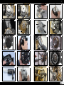
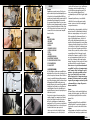
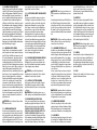
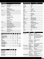
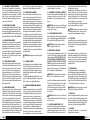
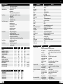
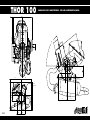
THOR 100
19
MANUALE D’USO E MANUTENZIONE - USE AND MAINTENANCE MANUAL
270,5
66,3°
65
54
Ø25
216
50
85
/on Ø
6 su
n.6 M
325
295
M8X4 holes
Ø30
85
40
202
asse elica
propeller axis
240
125
PI 415
125
125
125
5
4
01
02
11
12
03
04
13
14
1
2
Livello olio
Oil level
ITALIANO
05
06
15
16
07
08
17
18
09
10
19
20
ITALIANO
7
6
21
22
23
24
25
27
C
28
E
B
D
A
OPTIONAL
29
ITALIANO
26
30
ITALIANO
PREMESSA
Complimenti per aver acquistato un motore Polini. Con questa
scelta siete entrati a far parte di una distinta famiglia di possessori di un prodotto che vi darà grandi soddisfazioni THOR è stato
progettato in modo da garantire le migliori prestazioni possibili. Vi
raccomandiamo di leggere attentamente il presente manuale
d’uso e manutenzione prima di utilizzare il vostro nuovo motore.
Questo libretto contiene informazioni importanti che vi aiuteranno
ad ottenere il massimo della soddisfazione che l’utilizzo del motore Thor 100 può regalarvi. La perfetta messa a punto e la totale
conoscenza del vostro motore assicura sicurezza e tranquillità
durante il suo utilizzo.
INDICE
1- AVVERTENZE GENERALI
2- CARBURANTE
3- MESSA IN MOTO
4- RODAGGIO
5- SPEGNIMENTO DEL MOTORE
6- CONTROLLO CARBURAZIONE
7- PULIZIA
8- TRASPORTO
9- MANUTENZIONE ORDINARIA
10- MANUTENZIONI STRAORDINARIE
11- INSTALLAZIONE DEL MOTORE SUL TELAIO
12- TABELLE MANUTENZIONI
13- DIAGNOSI DIFETTI
1- AVVERTENZE GENERALI
La Polini ed il distributore declinano ogni responsabilità diretta o
indiretta legata all’uso del proprio motore, soprattutto nel caso in
cui il motore venga ritoccato o manomesso da terzi. La Polini non
si assume la responsabilità di danni causati dalla scarsa manutenzione o dall’errato montaggio, escludendo la sostituzione dei pezzi
dalla garanzia. Eventuali modifiche tecniche potranno essere
apportate dall’acquirente, che si assume tutta la responsabilità di
eventuali danni; i pezzi di ricambio a scopo di modifica non sono
coperti dalla garanzia. Si avverte che ogni modifica al motore
apportata dall’acquirente o la rimozione di parti originali possono
rendere il motore pericoloso!
L’utente è invitato a rispettare ed attenersi a quanto indicato e
consigliato nel manuale d’uso e manutenzione per l’incolumità
propria e di terzi. L’utilizzo che viene fatto di questo motore è
molto rischioso, quindi bisogna avere la massima attenzione
prima, durante e dopo il volo, per non incorrere in incidenti molto
gravi. Vi invitiamo pertanto ad essere accorti, in modo da prevenire incidenti e danni ed a tenere sempre presente che:
- il motore non può risolvere tutti i problemi di volo; bisogna pertanto evitare manovre poco sicure. Uno degli errori più
comuni è quello di sorvolare zone in cui non è possibile atterrare. Bisogna sempre considerare l’eventualità di un‘avaria e la necessità di effettuare un atterraggio di emergenza. E’ fatto divieto sorvolare centri abitati, agglomerati di case ed assembramenti di persone, nonché il lancio di oggetti o liquidi in volo.
-la mancanza di spinta del motore può creare disturbi alla stabilità del volo: il motore potrebbe spegnersi in qualsiasi momento e potreste essere costretti a fare un atterraggio di emergenza in una zona sicura.
Prima di ogni utilizzo, per la propria incolumità e quella di terzi, è
opportuno accertare che le condizioni climatiche ed atmosferiche
siano buone e comunque adeguate per un volo sicuro, anche al
fine di non pregiudicare il buon funzionamento del motore. La
pioggia o le condizioni climatiche avverse, oltre che fonte di
rischio, potrebbero, infatti, determinare danni al motore e comprometterne il regolare funzionamento. Non è consentito utilizzare il paramotore in condizioni di pioggia e forte vento. Volate solo
se la velocità del vento, la direzione e le condizioni meteo garantiscono un volo in sicurezza. E’ importante accertarsi delle previsioni meteo delle ore prossime al volo, nonché avere accortezza e
conoscenza della zona di decollo e di atterraggio. A causa dei
rischi insiti nell’uso del paramotore, e quindi del volo, la Polini
non concede nessuna garanzia contro incidenti, rotture, ferite o
morte. Volare con il paramotore richiede sempre la massima
attenzione. Siate consapevoli che volate a vostro rischio. Prima di
ogni utilizzo controllate le buone condizioni del paramotore.
Questo motore non è coperto da alcuna assicurazione di
responsabilità. L’uso dello stesso determina automaticamente l’assunzione di tutti i rischi inerenti lo sport del
paramotore e la personale responsabilità verso danni
propri o a terzi, incidenti, ferite o morte, derivanti
dall’uso di questo prodotto. Si invita pertanto a leggere
attentamente le istruzioni contenute in questo manuale,
in quanto utili per una maggiore conoscenza del prodotto
e padronanza dello stesso e dunque utili a prevenire e
misurare eventuali rischi.
Garanzia
Tutti i motori Polini sono costruiti con materiale di qualità per cui
si garantisce che il prodotto acquistato è privo di difetti, a condizione che l’acquirente acquisti il prodotto da un concessionario
autorizzato Polini.
Durata
La garanzia ha una durata di 24 mesi decorrenti dalla data di
vendita all'utente finale. E' necessario attivare la garanzia con
l'apposito modulo e conservare lo scontrino fiscale o la fattura.
Copertura
La presente garanzia copre i danni del motore causati da componenti difettosi per forma o materiale, per progettazione non conITALIANO
9
8
forme all’utilizzo indicato, assemblaggio non corretto da parte
della casa costruttrice. La Garanzia comprende pezzi di ricambio e
manodopera. Sono esclusi dalla garanzia i costi di trasporto, che
saranno a carico dell’utente. Sono esclusi dalla garanzia i danni
derivanti da:
- modifiche al motore non approvate dalla Polini
- normale logorio o usura dei componenti
- negligenza, mancanza di manutenzione, incidenti, installazione o manutenzione non corrette;
- cadute accidentali o caduta del motore o dei suoi componenti;
- un utilizzo improprio o dal maltrattamento del motore;
- uso di accessori o componenti non indicati nell’utilizzo del motore;
- surriscaldamento o fermo del motore a causa dell’uso prolungato, oltre il termine consigliato dalla Polini;
- mancata o regolare manutenzione del motore come indicato dalla Polini, uso di carburanti o lubrificanti non adatti, presenza di sporcizia o di corpi estranei nel motore, anche aspirati;
- affaticamento del motore per utilizzo di carichi eccessivi;
- deterioramento del motore o di parte di esso per custodia in luoghi non idonei;
- assemblaggio non corretto del motore, compreso l’uso di
componenti non originali Polini e comunque di proprietà di terzi;
- danni al motore derivanti da oggetti esterni;
- interventi di manutenzione da parte di soggetti diversi dalla Polini o da soggetti non autorizzati dalla Polini;
- utilizzo del motore per competizioni.
Adempimenti da parte dell’utente finale
Ogni reclamo dovrà essere effettuato consegnando il prodotto da
ispezionare ad un concessionario Polini autorizzato. L’acquirente
dovrà fornire la copia della “prova di acquisto” in originale o del
tagliando di garanzia regolarmente vidimato dalla Polini o dal
distributore. Per conservare la validità della garanzia il cliente
deve effettuare le manutenzioni periodiche previste dal manuale
di uso e manutenzione.
Limitazioni di responsabilità
Conformemente a quanto stipulato nella presente garanzia, gli
obblighi della Polini saranno limitati alla riparazione del componente difettoso o, a discrezione, alla sostituzione di uno o più
componenti, secondo quanto sarà ritenuto necessario per porre
rimedio ad ogni malfunzionamento dovuto ai difetti di materiale
o di manodopera coperti dalla garanzia. Alcuna responsabilità può
essere imputata alla Polini o al distributore del motore per ogni
problema o danno recato a persone/cose/animali riscontrato
durante tutta la vita del motore. Ricordiamo che questo prodotto
non è certificato ed è dedicato a velivoli sperimentali e
che in qualsiasi momento può rompersi o smettere di funzionare.
Pertanto non sono coperti né da garanzia né da risarcimento i
danni causati:
- a persone/animali/cose causati dall’utilizzo generico del motore.
- a persone/animali/cose causati da una collisione con l’elica o ITALIANO
una qualsiasi parte staccatasi dal motore.
- al telaio, componenti del velivolo e/o all’elica causati dalla collisione con una qualsiasi parte proveniente dal motore.
- spese di recupero, di spedizione, telefoniche o di noleggio di qualsiasi tipo, inconvenienti o perdite di tempo, o altri danni indiretti.
Pericolo! Questo motore, non certificato, può spegnersi di
colpo. L'interruzione del motore può provocare atterraggi di fortuna che possono produrre ferite o portare alla morte. Il velivolo
spinto da questo motore dovrebbe volare soltanto negli spazi
aperti e negli orari di luce. L'acquirente si assume tutto il
rischio per l’uso ed è consapevole che durante il suo utilizzo questo motore si potrebbe spegnere di colpo.
Questo prodotto non è coperto da responsabilità civile
prodotti. Chi vola con il paramotore o semplicemente lo
accende si assume tutti i rischi inerenti lo sport del
parapendio a motore ed ogni responsabilità per danni a
cose e a persone, o decesso causato dall’uso di questo
prodotto.
2- CARBURANTE
Il thor 100 è un motore a 2 tempi che necessita di una miscela di
benzina e olio. Utilizzare solo benzina verde acquistata al distributore con un numero di ottani compreso tra 95 e 98 di buona
qualità. Addizionare la benzina con olio sintetico di buona qualità
al 2% . E’ possibile utilizzare una miscela con olio al 1,5% utilizzando i seguenti oli:
MOTUL 800 - CASTROL 242 - BARDAL KXT - ELF 976 – ELF 909.
Esistono in commercio benzine con un basso potere antidetonante
che potrebbero creare grossi problemi di autoaccensione con relativo sfondamento del pistone o grippaggio. Prima del decollo provare sotto carico a motore caldo dai 7000/7500 giri: si potrebbero creare dei forti battiti in testa causando un rumore metallico. In
questo caso controllare la carburazione attraverso la candela che
muta dal colore naturale nocciola ad un grigio con incrostazioni
appuntite. Se persistono i problemi sostituire tutta la miscela cambiando il fornitore e verificare nuovamente la carburazione.
AVVERTENZA: il tipo di incrostazioni carboniose depositate
sulla testa, sulla candela e sullo scarico del cilindro sono informazioni che indicano il tipo di miscelazione del vostro motore. Si
rammenta che una combustione troppo ricca d’olio non allunga la
durata del motore.
ATTENZIONE: la benzina è estremamente infiammabile ed
esplosiva. Eseguire queste operazioni in un luogo ben ventilato e
a motore spento. Non fumare, non provocare scintille o fiamme
nell’area in cui la benzina viene conservata e dove avviene il
rifornimento.
3- MESSA IN MOTO
Avviare il motore solo dopo essersi accertati che sia tutto in ordine
e perfettamente funzionante. Verificare inoltre il corretto serraggio della bulloneria.
Primo avviamento a freddo: riempire il circuito di alimentazione
carburante utilizzando l’apposita pompetta (attenersi alle indicazioni del costruttore del telaio per l’individuazione ed il corretto
utilizzo di quest’ultima).Per facilitare l’operazione premere delicatamente con un dito la membrana del carburatore attraverso l’apposito foro indicato dalla freccia in foto 1 (non utilizzare oggetti
appuntiti che potrebbero rovinare la membrana compromettendone il corretto funzionamento). Il riempimento va eseguito fino a
quando non si vede arrivare la benzina al carburatore. Quando
ciò avviene fermarsi immediatamente; se si continua ad agire
sulla pompetta il carburante tende a filtrare all’interno provocando l’ingolfamento del motore. Posizionare la levetta dello starter
in posizione chiusa (foto 1): a questo punto impugnare l’avviatore
ed iniziare a tendere la fune fino a quando non si indurisce.
Tirare dunque con forza e decisione senza accelerare fino a quando il motore prova ad accendersi (non ripetere questa operazione
più di 3 volte altrimenti il motore potrebbe ingolfarsi), a questo
punto è necessario riposizionare la levetta dello starter in posizione aperta (foto 2) ed agire nuovamente sulla corda di avviamento senza accelerare. Se il motore non dovesse avviarsi con i primi
due colpi riprovare accelerando leggermente.
ATTENZIONE: Durante tutte le fasi tenere sempre in mano
l’interruttore di spegnimento e tenersi pronti ad azionarlo in qualsiasi caso di anomalia. Nel qual caso tenerlo premuto fino a completo spegnimento del motore.
Una volta avviato il motore consigliamo di fare un test di corretto
funzionamento del pulsante di spegnimento. Dopo il controllo
riavviare il motore senza accelerare e senza l’utilizzo dello starter.
A questo punto lasciar girare al minimo il motore dando delle leggere accelerate fino a portare il motore in temperatura.
4- RODAGGIO
Per ottimizzare l’assestamento del motore e della trasmissione al
primo funzionamento, preservando così da subito l’affidabilità, è
indispensabile un breve rodaggio. Attenersi pertanto alle seguenti
indicazioni: una volta avviato il motore farlo girare al minimo
dando delle leggere accelerate fino al raggiungimento della normale temperatura di esercizio. Consigliamo 15 minuti di avviamento motore a medio-bassa erogazione di potenza del motore
dando delle accelerate leggere e di diversa intensità. A questo
punto consigliamo di verificare la corretta taratura del minimo
(paragrafo 10.1).
Durante il primo volo o comunque per i primi 20 litri di carburante consigliamo di non tenere il motore al massimo dei giri per
troppo tempo, tenendo presente che il motore a 2 tempi mal sopporta i regimi di rotazione costanti anche se a media potenza.
Consigliamo dunque di cercare di variare il regime di rotazione
del motore. Dopo il primo atterraggio consigliamo di controllare la
carburazione (paragrafo 6). Ripetere il ciclo di rodaggio ogni
volta che viene sostituito uno qualsiasi dei seguenti particolari:
pistone, fasce elastiche, cilindro, albero motore o i cuscinetti di
banco.
5- SPEGNIMENTO DEL MOTORE
Per spegnere il motore azionare l’apposito pulsante fino a completo spegnimento (riferirsi alle indicazione del costruttore del
telaio per individuare la posizione del pulsante).
6- CONTROLLO CARBURAZIONE
Per una corretta analisi della carburazione spegnere il motore
subito dopo averlo fatto funzionare per alcuni minuti sotto carico.
Togliere la candela svitandola con apposita chiave e verificare il
colore della porcellana, che deve essere di colore nocciola. In caso
contrario rivolgersi ad un centro autorizzato per la regolazione.
7- PULIZIA
Effettuare la pulizia del motore solo a motore spento e freddo per
evitare pericoli di scottature. Pulire il motore utilizzando un panno
morbido imbevuto di prodotti neutri e non aggressivi.
AVVERTENZA: Non utilizzare acidi che potrebbero rovinare
il motore.
8- TRASPORTO
ATTENZIONE: Effettuare il trasporto solo quando il motore
è freddo.
Se, per necessità di trasporto, il motore viene posizionato orizzontalmente tappare il raccordo di sfiato del riduttore per evitare la
fuoriuscita dell’olio (foto3). Riferirsi alle indicazioni del costruttore
del telaio per un corretto trasporto. Porre molta attenzione al carburante durante il trasporto: una fuoriuscita dello stesso può causare un incendio.
9- MANUTENZIONE ORDINARIA
ATTENZIONE: LE OPERAZIONI DI MANUTENZIONE DEVONO
ESSERE EFFETTUATE ESCLUSIVAMENTE DA PERSONALE
COMPETENTE. QUALORA LE OPERAZIONI INDICATE NEI SUCCESSIVI
PUNTI DEL MANUALE NON FOSSERO CHIARE ALL’UTENTE, SI
CONSIGLIA DI CONSULTARE PERSONALE SPECIALIZZATO PRESSO I
RIVENDITORI O CONCESSIONARI POLINI MOTORI. ATTENERSI
SCRUPOLOSAMENTE A QUANTO INDICATO NEI SUCCESSIVI PUNTI
DEL MANUALE.
Le manutenzioni e gli interventi necessari per una messa a punto
ottimale del veicolo sono da intendersi come controlli quotidiani di
prima messa in moto del veicolo. Manutenzioni e regolazioni quotidiane sono facilmente eseguibili se fatte con le istruzioni dettate
da questo manuale d’assistenza. Le manutenzioni straordinarie
ITALIANO
11
10
sono dirottate presso i concessionari POLINI MOTORI che sostituiranno i particolari deteriorati esclusivamente con ricambi originali.
La frequenza della manutenzione ed il tipo d’intervento sono dettati dal paragrafo 12.
9.1- RIMOZIONE E PULIZIA DEL FILTRO ARIA
Un filtro aria sporco può compromettere le prestazioni del veicolo.
Provvedere periodicamente alla sua pulizia o eventuale sostituzione. Smontare il filtro allentando la fascetta, svitare le 4 viti utilizzando un cacciavite a croce, rimuovere il coperchio del filtro ed il
filtro stesso. Lavare il materiale filtrante in acqua calda con sapone neutro. Far asciugare accuratamente e successivamente umidificarlo con idoneo olio per filtri. Pulire con un panno l’interno
della scatola filtri assicurandosi che non vi siano corpi estranei. A
questo punto rimontare il tutto facendo attenzione a riposizionare
correttamente le 4 barrette che mantengono il filtro in posizione e
riavvitare le 4 viti. Un filtro può essere lavato 2-3 volte dopodiché
va sostituito con uno nuovo.
AVVERTENZA: Nel caso il filtro presentasse una forte concentrazione di polvere o impurità sostituirlo con uno nuovo
AVVERTENZA: La mancata pulizia del filtro soffoca il motore riducendone le prestazioni. Un filtro deteriorato può invece
facilitare l’immissione nel motore di particelle di polvere accelerando il normale deterioramento di fasce, pistone e cilindro.
9.2- CONTROLLO LIVELLO OLIO RIDUTTORE
(vedi anche paragrafo 11.4)
Effettuare queste operazioni a motore freddo. Mantenendo il
motore in posizione verticale togliere la vite di livello olio sul carter trasmissione (foto4). Verificare che il livello dell’olio sfiori il
bordo inferiore del foro. Nel caso vi fosse olio in eccesso lasciare
che esso fluisca dal foro di controllo raccogliendo l’olio in eccesso
con una bacinella per evitare che si disperda nell’ambiente. Se
l’olio non è a livello procedere al riempimento attraverso il raccordo di sfiato posto nella parte alta (foto3). Dopo aver eseguito il
controllo, stringere saldamente la vite. Utilizzare olio trasmissioni
che soddisfi la specifica API-GL4.
9.3- SOSTITUZIONE OLIO RIDUTTORE
Effettuare il cambio dell’olio a motore freddo. Svitare l’apposita
vite posta nella parte inferiore del gruppo riduzione/frizione.
Raccogliere l’olio che ne fuoriesce in un contenitore. Attendere che
tutto l’olio all’interno fuoriesca ed eventualmente inclinare leggermente il motore per facilitare l’operazione. Riavvitare saldamente
la vite. Svitare il raccordo/sfiato posto nella parte superiore del
carter ed inserire 25 cc di olio tipo API-GL4. Riposizionare il raccordo ed il relativo tubo.
AVVERTENZA: Non disperdere l’olio esausto nell’ambiente
ma consegnarlo agli enti designati per lo smaltimento.
ITALIANO
9.4- SOSTITUZIONE CORDA AVVIATORE
Rimuovere l’avviatore dal motore svitando le 4 viti (foto5).
Rimuovere il vecchio cordino. Fare attezione perché la ruota centrale ruoterà fino a completo scaricamento della molla; trattenerla
e farla scaricare lentamente in modo da evitare danni e pericolo
di farsi male. Preparare il cordino nuovo facendo un nodo ad un
capo dello stesso. Una volta completamente rimosso il vecchio cordino, trattenendo con una mano la parte esterna far ruotare la
parte interna in senso antiorario di 5 giri (foto 6). Fermare la
rotazione quando il foro nella ruota interna si trova in corrispondenza del foro sulla parte esterna (foto7). A questo punto prendere il nuovo cordino ed infilare in entrambi i fori contemporaneamente il capo non annodato del cordino (foto7) e far passare
completamente la fune fino a quando il nodo va in battuta
(foto8). Facendo ben attenzione a non mollare il cordino, lasciare
che la molla ritragga autonomamente il cordino avvongendolo
sulla ruota interna. Ora far passare il capo libero del cordino
attraverso la maniglia ed effettuare un nodo doppio (foto9).
Rimontare l’avviatore sul motore riavvitando le 4 viti M5 con la
necessaria forza (vedi tabelle serraggi).
9.5- SOSTITUZIONE MEMBRANE CARBURATORE
Rimuovere il filtro svitando con un cacciavite a croce la fascetta.
Dopo aver rimosso dal carburatore il cavo dell’acceleratore, la
molla supplementare, il tubo del carburante ed il tubo del depressore, svitare le due viti a brugola e rimuovere il carburatore dal
motore. Posizionarsi su un piano liscio e pulito. Rimuovere il
coperchietto superiore svitando le 4 viti (foto10), rimuovere la
membrana e la guarnizione, verificare la pulizia all’interno e
rimontare utilizzando la membrana nuova e la guarnizione nuova
(foto 11).
ATTENZIONE: Il carburatore è composto da numerose parti
molto piccole e molto delicate. Porre molta attenzione in ogni fase
con particolare cura allo spillo e la relativa molla; questi ultimi
non vanno toccati .
Rimuovere il coperchietto inferiore svitando le 4 viti (foto12),
rimuovere la membrana e la guarnizione, verificare la pulizia
all’interno con particolare attenzione al filtrino (foto13) e rimontare utilizzando la membrana nuova e la guarnizione nuova.
Rimontare il carburatore seguendo il procedimento inverso, facendo ben attenzione a posizionare correttamente tutte le guarnizioni.
10- MANUTENZIONI STRAORDINARIE
Premessa: la successiva sezione contiene nozioni necessarie per
eventuali tarature e riparazioni. E’ stato realizzato secondo la più
recente evoluzione di questa serie. Ci riserviamo comunque il
diritto di apportare modifiche migliorative senza obbligo di
aggiornamento del manuale stesso. Il manuale non contiene istruzioni riguardanti lavori generali che vengono eseguiti in officina,
né un elenco di regole per la sicurezza da rispettare in officina. Si
dà per scontato infatti che le riparazioni vengano effettuate da
personale specializzato.
10.1- REGOLAZIONE MINIMO
AVVERTENZA: Queste regolazioni devono essere effettuate
solamente da personale competente. Il motore viene consegnato
già regolato. Particolari condizioni atmosferiche o differenze di
altitudini possono richiedere una ulteriore piccola taratura del
minimo.
Il carburatore ha due viti per la regolazione del minimo (foto 14).
La vite 1 regola il flusso di benzina al minimo, la vite 2 regola
l’apertura della farfalla al minimo (quest’ultima viene detta anche
minimo meccanico). La taratura standard della vite 1 si ottiene
avvitando del tutto la vite e fermandosi immediatamente appena
si sente resistenza. Da questa posizione bisogna svitare la vite di
un giro e un ulteriore quarto di giro. Partendo dalla taratura standard si agisce poi sulle due viti per affinare la regolazione. Il regime di rotazione consigliato per il minimo è di 1600-1800 rpm.
10.2- VERIFICA/SOSTITUZIONE PACCO LAMELLARE
Rimuovere il filtro svitando con un cacciavite a croce la fascetta.
Dopo aver rimosso dal carburatore il cavo dell’acceleratore, la
molla supplementare, il tubo del carburante ed il tubo del depressore, svitare le due viti a brugola e rimuovere il carburatore dal
motore. Svitare le 4 viti a brugola del collettore e rimuovere lo
stesso. Estrarre il pacco lamellare e verificare che le lamelle siano
in buone condizioni e che la chiusura delle stessa sia perfetta. In
caso contrario sostituirle o sostituire l’intero pacco lamellare.
Rimontare il tutto seguendo il procedimento inverso, facendo ben
attenzione a posizionare correttamente tutte le guarnizioni.
10.3- MANUTENZIONE IMPIANTO DI SCARICO
Rimuovere il cavo di sicurezza controllandone la posizione in
modo da essere in grado successivamente di rimontarlo correttamente. Rimuovere le molle utilizzando l’apposito attrezzo (foto
15). Svitare le due viti che tengono la marmitta e rimuovere la
stessa dal motore. Non è necessario rimuovere il collettore dal
cilindro. Svitare le due viti che trattengono il silenziatore e rimuoverlo dal corpo marmitta. Utilizzando un trapano con una punta
diametro 5 mm, rimuovere i rivetti dal silenziatore e togliere i
due coperchi. Rimuovere il materiale fonoassorbente e gettarlo.
Pulire il tubo traforato dalle incrostazioni e dai residui ed avvolgerelo con il materiale fonoassorbente nuovo. Questo deve essere
ben schiacciato. Rimontare il tutto e bloccare con nuovi rivetti in
acciaio inox. Pulire la marmitta, rimontare il silenziatore sostituendo i gommini antivibranti. Rimontare l’intera marmitta sostituendo i supporti antivibranti e mettendo del grasso grafitato per
alte temperature sull’innesto sostituendo i due O-ring. Verificare
lo stato delle molle ed eventualmente sostituirle. Riposizionare il
cavetto di sicurezza facendolo passare attraverso le molle e gli
appositi fori sui prigionieri e bloccarlo su se stesso (foto 15).
ATTENZIONE: Utilizzare della pasta frena filetti su tutte le
viti durante il montaggio.
10.4- SMONTAGGIO VOLANO ACCENSIONE
Rimuovere l’avviatore, entrambe le parti del convogliatore aria e
la ventola. Per svitare il dado centrale del volano, tenere fermo lo
stesso utilizzando l’idoneo attrezzo posizionato nei due fori del
volano (foto16). Per rimuovere il volano è necessario utilizzare
l’estrattore cod. 928.695.002 (foto 17). Avvitare le 3 viti posizionando i 3 distanziali tra l’estrattore ed il volano. Consigliamo l’uso
di una pistola ad aria compressa per avvitare la vite centrale
dell’estrattore.
10.5- VERIFICA ACCENSIONE E BOBINA
Per capire in modo sommario se l’accensione o la bobina hanno
problemi si possono effettuare le seguenti verifiche sulle resistenze mediante l’uso di un tester. Accensione: misurando tra filo
rosso/nero e filo blu si devono leggere valori compresi tra 200 e
500 OHM. Misurando tra filo rosso/bianco e filo blu si devono
leggere valori compresi tra 1 e 20 OHM. Bobina: misurando tra
filo il cavo candela e filo nero si devono leggere valori compresi
tra 3500 e 7000 OHM.
10.6- MONTAGGIO VOLANO ACCENSIONE
Verificare che la chiavetta sia posizionata correttamente sull’albero motore ed inserire il volano innestandolo correttamente.
Avvitare la vite centrale e bloccarla utilizzando una chiave dinamometrica (vedi tabella coppie di serraggio). Per evitare la rotazione del volano è necessario utilizzare l’idoneo attrezzo posizionato nei due fori del volano (foto 16). Rimontare la ventola avvitando le 4 colonnette (utilizzare del frena filetti medio) e posizionare le 2 piastrine una sopra l’altra, facendo ben attenzione al
verso dei denti di innesto (foto 18).
10.7- SMONTAGGIO FRIZIONE-RIDUTTORE
Togliere il supporto elica svitando la vite centrale (foto 19).
Svuotare l’olio del gruppo trasmissione, svitando la vite posta
nella parte inferiore. Togliere le 8 viti del carter e rimuovere lo
stesso. Svitare la vite centrale della frizione utilizzando, per tenerla ferma, l’apposito attrezzo cod. 144.695.006 (foto 20). Per
rimuovere la frizione è necessario utilizzare l’apposito estrattore
cod. 144.695.004 avvitando le 3 viti; avvitare la vite centrale
eventualmente aiutandosi con un cacciavite per evitarne la rotazione (foto 21). Fare attenzione a non perdere la chiavetta posta
nell’apposita sede sull’albero. A questo punto è possibile rimuovere la campana e l’albero riduttore.
ITALIANO
13
12
10.8- MONTAGGIO FRIZIONE-RIDUTTORE
Verificare lo stato di usura delle 2 gabbie rulli ed eventualmente
sostituirle (foto 22). Posizionare nel cuscinetto superiore l’alberino
riduttore e infilare la campana sulle gabbie rulli. Posizionare la
molla a tazza sull’albero con la parte convessa rivolta verso il
motore (si consiglia di sostituire la molla a tazza ogni volta che
viene smontata). Posizionare la chiavetta nell’apposita sede
sull’albero motore e infilare la frizione. Avvitare la vite centrale e
bloccarla utilizzando una chiave dinamometrica (vedi tabella coppie di serraggio) e apposito attrezzo (foto 20). Rimontare il
coperchio verificando la presenza delle 2 spine di centraggio.
Sostituendo la guarnizione con una nuova, bloccare le 8 viti (vedi
tabella coppie di serraggio) utilizzando del frena filetti medio.
Posizionare sull’albero l’O-RING e successivamente la bussola con
lo smusso interno rivolto verso l’O-RING (foto 23). Rimontare la
flangia supporto elica e chiuderla utilizzando una chiave dinamometrica (vedi tabella coppie di serraggio).
10.9- SMONTAGGIO GRUPPO TERMICO
Smontare l’avviatore e successivamente rimuovere entrambe le
parti del convogliatore aria. Smontare l’impianto di scarico (paragrafo 10.3). Svitare i 4 dadi della testa e rimuovere testa e cilindro. Procedere alla manutenzione o alla sostituzione delle parti
interessate. Eseguire un’accurata pulizia della testa togliendo
eventuali incrostazioni carboniose e pulire il forellino di decompressione (foto 24). Prima del ri-montaggio lavare accuratamente
cilindro, pistone e testa con solventi e soffiare con un getto di aria
compressa. Oliare leggermente la canna del cilindro e tutte le
parti in movimento con olio per miscela. Montare il pistone con la
freccia rivolta verso lo scarico; in mancanza della freccia, montare
il pistone con i fermi dei segmenti rivolti verso l’aspirazione.
Controllare che gli anellini di fermo spinotto entrino perfettamente nella loro sede e non abbiano gioco. Posizionare il cilindro
senza segmenti e, ruotando l’albero motore, verificare che il
pistone scorra senza alcun attrito. In presenza di qualsiasi tipo di
problema, ricercare la causa ed eliminarla. Rimontare posizionando la guarnizione di base nuova, montare i segmenti, il cilindro e
la testa con la relativa guarnizione nuova; bloccare i dadi di fissaggio in senso incrociato. Rimontare tutte le parti del motore
precedentemente tolte.
ATTENZIONE: In caso di sostituzione del pistone verificare
che la selezione sia corretta.
10.10- APERTURA CARTER MOTORE
Una volta rimossi tutti i particolari dal motore, compreso il supporto, assicurarsi di aver tolto tutte le viti dei carter centrali. Per
aprire i carter centrali è necessario utilizzare l’apposito estrattore
cod. 928.695.001 avvitando le 2 viti e agendo poi sulla vite centrale fino a completa apertura dei carter (foto 25). Per estrarre
l’albero motore dall’altra metà carter è necessario agire con una
ITALIANO
pressa posizionando il carter su degli appositi sostegni (foto 26) e
spingere sull’albero motore fino ad estrazione.
10.11- SOSTITUZIONE CUSCINETTI E CHIUSURA CARTER
MOTORE
Per rimuovere i cuscinetti scaldare i carter motore in un forno a
130-140 gradi. Se si posizionano i carter all’interno del forno con
i cuscinetti rivolti verso il basso, questi dovrebbero cadere da soli,
altrimenti picchiare delicatamente con un perno per facilitarne
l’uscita. Preparare i cuscinetti nuovi, meglio se raffreddati precedentemente in freezer, e, sempre con il carter caldo, farli cadere
nella propria sede, assicurandosi che siano bene in battuta.
Attendere qualche minuto che i cuscinetti si siano scaldati, a questo punto l’albero motore entrerà libero nel cuscinetto. Richiudere
le due metà dei carter utilizzando una nuova guarnizione, facendo attenzione alle bussole di centraggio. Chiudere le viti del carter
con la coppia di serraggio consigliata (vedi tabella serraggi). Una
volta serrate le viti dare uno o due colpi con un martello di rame
sulle due estremità dell’albero motore per facilitarne l’assestamento e verificare che sia in grado di ruotare liberamente.
Procedere al rimontaggio degli altri componenti.
10.12- REGOLAZIONE REGIME DI AGGANCIO FRIZIONE
La frizione viene regolata in fabbrica con un aggancio a circa
4000 giri/min. Se fosse necessario variare tale regime si potrà
agire sui 3 dadi per affinare la taratura. Avvitare per aumentare
il regime di aggancio, svitare per abbassarlo.
ATTENZIONE: agire sui 3 dadi nel medesimo modo.
Consigliamo di spostare la regolazione di ¼ di giro e verificare il
cambiamento. Se necessario ripetere l'operazione.
10.13- CONTROLLO/SOSTITUZIONE CANDELA
Togliere il cappuccio candela e svitare la candela con l'apposita
chiave. Utilizzando uno spessimetro verificare che la distanza
degli elettrodi candela sia di 0,9 mm. Se così non fosse ripristinare tale misura.
ATTENZIONE: anche le candele nuove devono essere controllate e regolate per avere la distanza di 0,9mm. tra gli elettrodi.
11- INSTALLAZIONE DEL MOTORE SUL TELAIO
Il motore viene consegnato all’interno di una scatola avvitato su
una gabbia per proteggerlo durante il trasporto. Svitare le 4 viti
M8 che lo tengono fissato ed estrarre il motore dalla gabbia.
CONSERVARE LA SCATOLA E RELATIVA GABBIA PER QUALSIASI
RIPARAZIONE IN GARANZIA. NON VERRANNO ACCETTATI RESI IN
GARANZIA SE NON NELL’IMBALLO ORIGINALE. Il motore deve
essere fissato sul telaio utilizzando i 4 fissaggi provvisti di silentblock eventualmente posizionando dei distanziali qualora il telaio
non fosse provvisto di uno spazio sufficiente per l’avviatore
manuale. Fare riferimento al disegno per le misure di attacco al
telaio.
ATTENZIONE: Il motore deve essere posizionato come in
figura. Per garantire una corretta lubrificazione non può essere
ruotato.
Per motivi di ingombro durante il trasporto il filtro dell’aria è ruotato di 180 gradi. Senza svitare la fascetta ruotare il suddetto
nella posizione corretta. Il filtro è inoltre provvisto nella parte alta
di un foro che deve essere utilizzato per evitare la rotazione del
filtro durante l’uso. Per fare ciò posizionare una fascetta o un
cavetto (non forniti) fissando il suddetto ad una zona adatta del
telaio.
ATTENZIONE: Se il filtro non viene fissato potrebbe ruotare,
entrare in collisione con l’elica e provocarne la rottura. Ciò può
essere molto pericoloso per la sicurezza.
11.1- COLLEGAMENTI ELETTRICI (foto27)
La bobina deve essere fissata saldamente sul telaio utilizzando i 2
fori ed opportune viti in una posizione che permetta al filo della
candela con il cappuccio candela montata di raggiungere agevolmente la candela. Eventualmente tale filo può essere tagliato se
risultasse troppo lungo. Il cavo nero provvisto di occhiello(A) che
esce dalla bobina deve essere fissato insieme al cavo azzurro
provvisto di occhiello (D), entrambi poi posti a massa sul motore.
Il cavo azzurro della bobina (B) deve essere collegato al cavo rosso-nero dello statore.
Lo statore è provvisto di connettore che può essere collegato al
regolatore di tensione (optional); in questo caso si ottiene sul cavo
rosso (E) provvisto di occhiello una tensione di +12V costante
quando il motore è acceso. Se non si utilizza il regolatore di tensione fissare il cavo e il connettore al telaio. L’ulteriore cavo rossonero (C) deve essere opportunamente collegato a massa tramite
apposito interruttore di spegnimento motore (non compreso).
apertura della farfalla del carburatore e verificare che il ritorno
sia buono in modo da evitare che il motore resti accelerato.
Verificare la presenza e la corretta installazione della molla supplementare di ritorno (foto28).
11.4- RIDUTTORE
Il riduttore viene riempito con la giusta quantità d’olio direttamente in fabbrica, dunque per la spedizione viene posizionato un
piccolo tubo di gomma tappato sullo sfiato per evitarne la fuoriuscita. Il suddetto tubicino deve dunque essere rimosso e conservato per futuri trasporti e al suo posto deve essere installato il tubo
in dotazione (foto29). Assicurarsi che il tubo sia ben fissato applicando eventualmente delle fascette per assicurarsi che non possa
entrare in collisione con l’elica. Verificare comunque il livello
dell’olio svitando l’apposita vite di livello (foto4).
ATTENZIONE: all’interno del gruppo riduttore è presente
anche la frizione che lavora in bagno d’olio. E’ necessario dunque
utilizzare un olio specifico tipo API-GL4.
11.5- CANDELA
Smontare la candela e verificare che la distanza tra gli elettrodi
sia pari a 0,9 mm. Inserire il cappuccio candela all’interno del
tappo convogliatore avendo cura di inserirlo completamente.
Successivamente innestare sulla candela facendo entrare il gommino all’interno del foro nel convogliatore in plastica. (Foto 30).
Candela tipo NGK BR10EG.
11.6- ELICA
Utilizzare solo eliche consigliate. L’uso di un’elica non corretta può
pregiudicare il funzionamento del motore.
ATTENZIONE: è importante verificare il corretto funzionamento del pulsante di spegnimento per essere in grado di spegnere il motore in qualsiasi momento. Il non corretto funzionamento
dello spegnimento può essere molto pericoloso.
11.2- ALIMENTAZIONE CARBURANTE
Il telaio deve essere predisposto con idoneo serbatoio e relativa
pompetta per far arrivare il carburante al carburatore. Collegare
il tubo benzina all’apposito raccordo sul carburatore fissandolo
con una fascetta e verificando che non ci siano trafilaggi di aria.
11.3- ACCELERATORE
Fissare al carburatore tramite l’apposito supporto idoneo acceleratore (non fornito). Dopo l’installazione dell’acceleratore verificare
che la corsa dello stesso sia sufficiente per avere una completa
ITALIANO
15
14
12- TABELLA MANUTENZIONI
Ogni utilizzo
Controllare il serraggio della viteria
Controllo visivo silent-block
Dopo le prime 10 ore
Sostituzione olio riduttore
Verifica carburazione
Controllo distanza elettrodi candela
Ogni 25 ore
Sostituzione candela e regolazione distanza elettrodi
Pulizia filtro aria
Sostituzione olio riduttore
Sostituzione molle marmitta
Ogni 100 ore o ogni anno
Sostituzione filtro aria
Sostituzione corda avviamento a strappo
Sostituzione membrane carburatore e pulizia
Sostituzione silent-block
Sostituzione tubi circuito di alimentazione
Sostituzione lamelle
Ogni 100 ore
Verifica pistone e fasce elastiche
Sostituzione spinotto e gabbia a rulli
Decarbonizzazione e pulizia foro decompressore
Sostituzione materiale fonoassorbente silenziatore
Smontaggio riduttore e verifica usura frizione e campana
Ogni 200 ore
Sostituzione pistone e fasce elastiche
Sostituzione pacco lamellare
Ogni 400 ore
Sostituzione di tutti i cuscinetti e paraoli
Sostituzione albero motore
TABELLA COPPIE DI SERRAGGIO MINUTERIA MOTORE
DADI TESTA
DADO ALBERO MOTORE LATO FRIZIONE
DADO ALBERO MOTORE LATO ACCENSIONE
VITE CENTRALE ELICA
CANDELA
VITI CARTER MOTORE
VITI FISSAGGIO CARBURATORE
VITI FISSAGGIO COLLETTORE ASPIRAZIONE
DADI PRIGIONIERI MARMITTA
VITI FISSAGGIO SILENZIATORE
VITI FISSAGGIO MARMITTA
VALORI DI COPPIA STANDARD
Bullone e dado da 5 mm
Bullone e dado da 6 mm
Bullone e dado da 8 mm
Bullone e dado da 10 mm
Bullone e dado da 12 mm
ITALIANO
M
7
12
10
10
6
6
6
6
8
8
N.m
14
60
40
40
20
8
8
8
10
15
15
Kgf.m
1,4
6
4
4
2
0,8
0,8
0,8
1
1,5
1,5
N.m
6
10
25
45
55
Kgf.m
0,6
1
2,5
4,5
5,5
Lbf.ft
4,44
7,40
18,50
33,30
40,70
SCHEDA TECNICA - TECHNICAL LIST
Motore Polini
Raffreddamento
Alesaggio per corsa
Cilindrata
Potenza
Spinta statica
Cilindro
Rapporto compressione
Pistone
Aspirazione
Carburatore
Filtro aria
Accensione
Predisposizione carica batteria
Candela
Capuccio candela
Alimentazione
Riduttore ingranaggi
Avviamento
Frizione
Marmitta
Consumo
Peso motore
Rotazione elica
Lbf.ft
10,36
44,4
29,6
29,6
14,8
5,92
5,92
5,92
7,4
11,1
11,1
frena filetto
Loctite 243
Loctite 270
Loctite 243
Loctite 243
13- DIAGNOSI DIFETTI
Il motore non si accende
THOR 100
Monocilindrico 2T
Ad aria forzata
52 x 52
110 cm3
20,5 HP a 8900 R.P.M.
Ø 130 - 64 Kg.
In alluminio con riporto Gilnisil
12,5:1
Due fasce cromate mm1
Valvola lamellare nel carter
WG8 POLINI
Air box Polini
Elettronica con possibile carica batteria
Potenza in uscita 80W a 5500 giri/m
NGK BR10EG (distanza elettrodi 0,9 mm.)
Con resistenza 5 K Ω
Benzina verde con olio sintetico al 2%
Denti elicoidali in bagno d’olio rapporto riduzione 3,43
A strappo con fune autoavvolgente
Centrifuga a bagno d’olio
Espansione con silenziatore ovale
2,7/3 litri /ora a 6500 giri - 30 Kg. di spinta
11,8 Kg.
Senso orario
CAUSA
Mancanca di benzina
Non arriva benzina al carburatore
Benzina vecchia o non idonea
RIMEDIO
Aggiungere carburante
Verificare il circuito di alimentazione carburante
Svuotare il serbatoio e il circuito di alimentazione e sostituire la benzina
Smontare la candela, far girare il motore azionando l’avviamento,
Motore ingolfato
rimontare la candela asciugandola o sostituendola
Candela difettosa
Sostituirla
Candela annerita o bagnata
Pulire ed asciugare la candela o sostituirla
Cavo di spegnimento a massa
Verifica cablaggio
Cappuccio candela mal innestato Verifica
Pulizia e verifica del carburatore, eventuale sostituzione membrane
Il carburatore ha dei problemi
Non c’è scintilla
Verifica accensione, bobina e cablaggio
Il motore non tiene il minimo
Carburatore sporco
Pulizia e verifica del carburatore
Viti di regolazione sregolate
Far tarare il carburatore
Candela difettosa
Sostituirla
Il motore non raggiunge il regime massimo Carburazione errata
Far tarare il carburatore
Pulizia e verifica del carburatore, eventuale sostituzione membrane
Il carburatore ha dei problemi
Il pacco lamellare ha dei problemi Sostituzione delle lamelle o dell’intero pacco lamellare
Filtro aria sporco
Pulizia o sostituzione
Impianto di scarico sporco
Pulizia e sostituzione materiale fonoassorbente
Il motore al minimo rimane su di giri Viti di regolazione sregolate
Far tarare il carburatore
Trafilaggio di aria dalle guarnizioni Sostituzione delle guarnizioni e paraoli
ITALIANO
17
16
ENGLISH
INTRODUCTION
Congratulation for purchasing a Polini engine. By purchasing it
you have become one of a large family of satisfied Polini products
owners. This product has been designed to perform as competitively as possible. Read this use and maintenance manual carefully
throughout before flying with your new engine. This manual contains important information that will help you to achieve the best
satisfactions with the use of the Thor 100 engine. To ensure carefree and satisfying usage you must get to know your new engine
thoroughly and set it up correctly before you start using it.
CONTENTS
1- GENERAL ADVICE
2- FUEL
3- ENGINE STARTING
4- RUNNING IN
5- ENGINE SWITCING OFF
6- CARBURETION CHECK
7- CLEANING
8- CARRIAGE
9- ORDINARY SERVICING
10- EXTRAORDINARY REPAIRS
11- ENGINE FITTING ON THE FRAME
12- SERVICING TABLES
13- ENGINE PROBLEMS DIAGNOSTIC
1 GENERAL ADVICE
Polini Motori and the distributors decline any and all responsibility
whatsoever - either direct or indirect - for the use of the engine,
above all in the case the engine is modified or manumitted by
third parties. Polini Motori doesn’t assume responsibility for
damages caused by little servicing or wrong assembly, excluding
the pieces from the warranty. Any technical modification may be
introduced by the buyer, who assumes all the responsibilities for
possible damages; spare parts for any modification are not under
warranty. We advice you that any engine modification made by
the buyer or the removal of original parts may make the engine
dangerous to be used!
The user is invited to respect and follow what written in the use
and maintenance manual for his own and third parties safety.
When you use this engine you are making a very dangerous
action, so you may have the maximum care before, during and
after flying, in order to avoid serious accidents. We invite you to
be careful to prevent accidents or damages and to keep always in
mind that:
-the engine can’t solve all the flight problems, so it is important to avoid dangerous maneuverings. One of the most common errors is to fly over zones where it is not allowed to land; you have always to take into consideration the possibility of engine failure ENGLISH
or the need to make an emergency landing. It is forbidden to fly over built-up areas, urban centers, to drop things or liquids when flying.
- the lack of engine power can disturb the flight stability: the engine could stop suddenly and you may be obliged to make an emergency landing on a safety area.
Before using it, for your own and third parties safety, it is necessary to be sure that the weather conditions are good, or anyway
adequate for a safety flight, in order not to compromise the good
engine work. Rain or unfavorable weather conditions, besides
being dangerous, could also damage the engine, prejudicing its
normal working. It is not allowed to use the paramotor when raining or with strong wind. Only fly if the wind speed, its direction
and the conditions grant a safety flight. It is important to check
the weather forecasting for the hours close to the flight and to
know the taking off and landing areas. Because of the risks inherent to the paramotor use, and the flight, Polini doesn’t give any
warranty against accidents, breakings, injuries or death. To fly
with a paramotor always needs great attention. Be aware that
you fly at your risk. Before every use check the good condition of
your paramotor. This engine is not covered by any responsibility insurance. By using it you automatically assume
all the risks inherent the paramotor sport or the personal responsibility towards damages to yourself or to
third parties, accidents, injuries or death. We invite you
to carefully read the instructions contained in this
manual since they are helpful for a better knowledge of
the products and the use itself and useful to prevent
and contain the risks.
Warranty
All the Polini engines are manufactured with high quality materials which grant a product without defects, under the conditions
that the buyer purchase the products from an authorized Polini’s
dealer
Validity of the warranty
The warranty is valid for a period of 24 months from the date of
purchase. It is necessary to activate the warranty by filling the
form out and keeping the payment slip or the invoice.
Coverage
The present warranty covers the engine damages caused by defective parts, in shape or materials, for projects not in conformity
with the use indicated, wrong assembly by the manufacturer. The
warranty includes spare parts and labor. Delivery costs are charged to the user.
The warranty doesn’t cover damaged caused by:
- Engine modifications not approved by Polini;
- Wear and tear of the parts;
- Carelessness, lack of servicing, accidents, installations or wrong maintenance;
- Accidental fall or the engine fall or of its components;
- Engine improper use or misusage;
- Assembly of parts or components not specified for the engine use;
- Engine overheating or stop for long usage, beyond the term indicated by Polini;
- Missing or irregular engine servicing as suggested by Polini, use of improper petrol or oils, presence of dirty parts or foreign bodies in the engine, even sucked;
- Engine overwork because overloaded;
- Engine or parts deterioration because of improperly storage;
- Faulty engine assembly, including the use of not original Polini parts or coming from third parties;
- Damages to the engine caused by foreign bodies;
- Servicing operated by person outside Polini or by not authorized people;
- Competition use of the engine.
Final user obligations
Claims shall be done by delivering the engine to an authorized
Polini dealer. The user shall provide the original document that
proves the purchasing or the warranty ticket authenticated by
Polini or by its distributor. To keep the validity of the warranty the
user shall carry out recurrent servicing according to the use and
maintenance manual.
Limited liability
Pursuant to this warranty, Polini’s obligations are limited to the
defective parts reparation or, at its discretion, to change one or
more parts, necessary to remedy every malfunctioning caused by
defective materials or labor covered by the warranty. Polini or the
distributor can’t be held responsible for problems or damages to
persons/things/animals during the engine life. We remind you
that this product is not certificated and it is only dedicated to
experimental aircraft and that it can break or suddenly stop working. No warranty or compensation are foreseen for damages
caused to:
- persons/animals/things during the engine use
- persons/animals/things caused by a collide with the propeller or with parts detached from the engine
- frame, parts and/or propeller caused by the collide with parts coming out from the engine
- costs for rescue, shipping, phone or rent after the collide, problems or lose of time, or other indirect damages.
DANGER! This not-certified engine can suddenly stop working. The engine stop can require emergency landings causing
injuries or death. The aircrafts thrust by this engine should fly in
open spaces only or during the daylight. The buyer assumes all
the risks for the use and he knows that by using it the engine can
suddenly stop working. This product is not covered by products
and public liability. Who flies with a paramotor or only switch it on
assumes all the risks inherent to the paragliding sport and all the
responsibilities for damages to things or persons or death caused
by the use of this product.
2- FUEL
Thor 100 is a 2-stroke engine that needs oil/petrol mixture. Only
use good lead-free petrol purchased by a petrol station with a
number of octane between 95 and 98. Add good 2% synthetic oil
to the petrol. It is possible to use a 1,5% oil mixture with the following oils:
MOTUL 800 - CASTROL 242 - BARDAL KXT - ELF 976 - ELF 909.
Petrol with low antiknock value may cause serious problems when
starting the engine, destroying the piston or seizing the cylinder.
Before taking off test, warm the engine and test it at 7000/7500
rpm: some knocks can be generated causing a metal noise. In this
case check the carburetion and look at the spark plug color that
changes from a natural light-brown color to a grey color with
sharpened deposits. If the problems persist, change all the mixture with a different brand one and check the carburetion again.
WARNING: The nature of the carbon deposits on the cylinder
head, spark plug and exhaust port gives important information
about the fuel mixture burning in your engine. Remember that
mixes that contain too much oil do not extend the engine’s life.
ATTENTION: petrol is extremely inflammable and explosive.
Carry out these operations in a well ventilate place and with the
engine switched off. Refrain from smoking and avoid all naked
flames or sparks where petrol is being drained or where re-fuelling is being performed.
3- ENGINE STARTING
Start the engine only when all is in good conditions and perfectly
working. Furthermore check that all the nuts are well tightened.
First cold starting: fill in the fuel system using the pump provided
(carefully follow the instructions provided by the frame’s manufacturer to find out it and use it in the correct way). To make this
operation easier push softly with a finger the diaphragm through
the hole indicated by the arrow in photo 1 (do not use sharpened
tools that may damage the diaphragm, compromising its functioning). Fill it in till the petrol reaches the carburettor. At that
moment immediately stop; if you go on acting on the pump the
petrol will leak causing the engine flooding. Move the starter level
to the off position (photo 1); now hand the starter and start pulling the rope till it grows hard. Pull with strength without accelerating till the engine seems to start working (do not repeat this operation more than 3 times otherwise the engine may flood). Now
move the starter lever to the on position (photo 2) and act on the
starting rope without accelerating. If the engine doesn’t work with
the first two attempts, try again accelerating gently.
ENGLISH
19
18
ATTENTION: during this operation always keep the stop
switch in hand and be ready to activate it in case of defect. If it
happens keep it pressed till the engine stops.
Once the engine works we suggest testing the stop switch works
perfectly. After this operation re-start the engine without acceleration and without using the starter. Now leave it idle accelerating
and then until the engine warms up to normal temperature.
9- ORDINARY SERVICING
4- RUNNING IN
Run your engine in as instructed below to ensure that the engine
and transmission bed in correctly and to ensure continuous reliability in future. Once the engine starts, leave it idle until it warms
up to normal temperature. We suggest running the engine 15
minutes at medium-low engine power output gently accelerating
and with different intensity. Now we suggest checking the correct
idling calibration. (section 10.1)
During the first flight or for the first 20 litres of petrol we suggest
not keeping the engine at the maximum rpm for too much time,
considering that the 2-stroke engine doesn’t stand to the constant
rpm even if of medium power. We suggest varying the engine
rpm. Check the carburetion after the first landing (section 6).
Repeat the running in every time you change one of the following
parts: piston, rings, cylinder, crankshaft or main bearings.
Maintenances and servicing necessary for the best set up of your
engine should be done regularly, or on all occasions before you
start flying. All the tasks and adjustments described below can be
done easily by following the instructions given in this manual.
Refer to your POLINI MOTORI dealer for scheduled services and
repairs, and insist that only original spare parts are used to replace worn or broken components. Refer to the servicing tables in
sections 12 below for the frequency with which the various servicing operations must be performed.
5- ENGINE SWITCING OFF
Switch the engine off by pressing the button till the complete stop
(see the frame manufacturer’s instructions to find the button position)
6- CARBURETION CHECK
For a complete carburetion check switch the engine off after
having worked it for some minutes under load. Remove the spark
plug; unscrew it by using the proper key and verify that the porcelain colour is light-brown. On the contrary, ask to an authorized
dealer for the calibration.
7- CLEANING
Clean the engine when it is switched off and cold to avoid burns.
Clean the engine with a soft cloth soaked with neutral cleansing
and non-aggressive.
WARNING: Do not use acids that may damage the engine.
8- CARRIAGE
ATTENTION: Carry the engine only when cold.
If the engine is carried in horizontal position, plug the breather
pipe of the transmission case to avoid oil leaking (photo 3).
Follow the instructions of the frame manufacturer for its carriage.
Be careful of the petrol during the carriage; its leaking may cause
a fire.
ENGLISH
ATTENTION: THE SERVICING OPERATIONS MUST BE DONE BY
QUALIFIED PEOPLE ONLY. IF THE INSTRUCTIONS MENTIONED
BELOW WILL RESULT NOT CLEAR, WE SUGGEST ASKING FOR
SPECIALISTS BY POLINI MOTORI RETAILERS OR WHOLESALERS.
FOLLOW CAREFULLY WHAT DESCRIBED BELOW.
9.1- REMOVE AND CLEAN THE AIR FILTER
Dirty air filter is one of the most common causes of poor engine
performance.
Clean the filter periodically or change it. Remove the filter loosening the clamps, unscrew the 4 screws using a cross screwdriver,
remove the filter cover and then the filter. Wash the filtering
material with water and mild soap.
After rinsing and wringing the filter, moisten it with oil for filters.
Clean filter box inside using a cloth and check the presence of
foreign bodies. Now reassemble all the parts being careful to
place correctly the 4 bars that maintain the filter in its position
and screw the 4 screws again. Wash the filter for maximum 2-3
times, then replace it.
WARNING. If the filter becomes clogged with fine dust as
well as normal dirt, replace it with a new one.
WARNING. Dirty air filters choke the engine and cause poor
performance. Torn or broken filters can allow dirt to enter the
engine and cause rapid deterioration of the piston rings, piston
and barrel.
9.2- CHECKING OF THE GEAR OIL LEVEL
Operate when the engine is cold. Maintain the engine in vertical
position and remove the oil level screw on the transmission crankcase. (photo 4). Check that the oil level reaches the lower edge
of the level hole. If there is too much oil, let it flow out from the
level hole until it stops flowing and collect the oil in a suitable
container. If there is not enough oil, top up as required through
the breather hole located at the top (photo 3). After checking it,
tighten the screws. Use API-GL4 oil.
9.3- GEAR OIL REPLACEMENT
Change the oil when the engine is cold. Unscrew the screw on the
lower side of the clutch/gear group. Collect the oil flowing out in
a suitable container. Wait till the oil has completely flown out and,
if necessary, tilt the engine to the side to make this operation
easier. Tighten the screws. Unscrew the breather pipe in the top
side of the carter and fill it out with 25cc API-GL4 oil. Replace the
pipe and its tube.
WARNING: Do not throw spent oil into the environment.
Dispose of it correctly through authorised collection points.
9.4- STARTER ROPE REPLACEMENT
Remove the starter from the engine unscrewing the 4 screws
(Photo 5). Remove the old rope. Be careful since the central
wheel will turn till the complete spring discharge: keep it and
discharge it slowly to avoid damages or possible injuries. Prepare
the new rope and tie a knot at the top. Once the old rope has
been completely removed, keep with a hand the external side and
make the inside part rotate in anticlockwise for 5 times (photo 6).
Stop rotating when the hole in the wheel is at the hole level on
the outside part (photo 7). Now take the new rope and thread in
both the holes the head without knot (photo 7) and make the
rope pass completely till the knot beats (photo 8). Being careful
not to leave the rope, let the spring withdraw automatically the
rope winding it up on the inside wheel. Now make the free rope
head pass through the handle and tie a double knot (photo 9).
Reassemble the starter in the engine and screw the 4 M5 screws
with strength (see the tightening torque values table).
9.5- DIAPHRAGM CHANGING
Remove the filter unscrewing the clamp by using a cross screwdriver. After removing the accelerator cable from the carburettor, the
supplementary spring, the carburettor pipe and the diffusion pipe
unscrew the two socket head screws and remove the carburettor
from the engine. Now place the parts on a flat plane. Remove the
upper cover by unscrewing the 4 screws (photo 10), remove the
diaphragm and the gasket, check that the inside part is clean and
reassemble by using the new diaphragm and the new gasket
(photo 11).
ATTENTION: The carburettor is made of many small and
delicate parts. Be very careful during all the phase with particular
attention to the idling and its springs; they both must not be touched.
10- EXTRAORDINARY REPAIRS
Introduction: the following section contains information for calibration and reparations. It has been done according to the latest
evolutions of this series: we reserve the right to change and
improve the product without the obligation to review this manual.
The manual doesn’t include instructions concerning general workings that may be made in the workshop neither a list of wor-
kshop safety rules to be respected. It is taken for granted that
reparations are made by specialists.
10.1- ADJUSTING ENGINE IDLING SPEED
WARNING: These regulations must be done by specialists
only. The engine comes with a standard calibration. Particular
weather conditions or different altitudes can require a different
adjustment of the idling.
The engine has two screws to adjust the idling (photo 14). Screw 1
adjusts the petrol flow at the idling, while screw 2 adjusts the
throttle valve opening at the idling (even called mechanic idling).
Standard calibration of screw 1 can be done by screwing the screw
completely but stopping when you feel resistance. From this position unscrew the screw of one turn and then a quarter of turn.
Starting from the standard calibration you have to act on both the
screws to adjust it. The suggested speed rate for the idling is
1600-1800 rpm
10.2- CHECK-REPLACE THE REED VALVE
Remove the filter unscrewing the clamp by using a cross screwdriver.
After removing the accelerator cable from the carburettor, the supplementary spring, the carburettor pipe and the diffusion pipe
unscrew the two socket head screws and remove the carburettor
from the engine. Unscrew the 4 manifold’s socket head screws and
take the manifold away. Remove the reed valve and check that the
reeds are in good conditions. On the contrary, change the whole reed
valve. Re-assemble all the parts following the inverted procedure
and being very careful to place all the gaskets in their housings.
10.3- EXHAUST SYSTEM SERVICING
Remove the security cable and keep in mind its position in order
to be able to fit it again. Take the springs away by using the proper tool (photo 15). Unscrew the two screws that keep the muffler
and remove it from the engine. Do not remove the manifold from
the cylinder. Unscrew the two screws that keep the silencer and
remove it from the muffler. Using a 5mm drill remove the rivets
from the silencer and take the two covers away. Remove the deadening material and through it away. Clean it from deposits and
residuals and wrap up the perforated pipe with new deadening
material. It must be well pressed. Assemble all the parts again
and lock them with new steel rivets. Clean the muffler, reassemble
the silencer changing the vibration small rubbers. Fit the whole
muffler changing the silent blocks and inserting in the coupling
some graphite grease resistant to high temperatures and change
the o-rings. Verify the springs conditions and if necessary change
them. Fit the security cable making it pass through the springs
and their holes on the studs and lock it on itself (photo 15).
ATTENTION: use thread locking paste on all the screw when
assembling.
ENGLISH
21
20
10.4- DISASSEMBLY OF THE IGNITION FLYWHEEL
Remove the starter, both the parts of the air conveyor and the
fan. In order to unscrew the flywheel central nut hold it using a
proper tool placed on the two flywheel holes (photo 16). To remove the flywheel it is necessary to use puller, part no. 928.695.002
(photo 17); screw the 3 screws by placing the 3 spacers between
the puller and the flywheel. We suggest using a compressed air
gun to screw the puller central nut.
10.5- IGNITION AND COIL CHECKING
To find out if the ignition and the coil may be defective, using a
tester make the following verifications on its resistance. Ignition:
the measures between red /black cable and blue cable must be
between 200 and 500 OHM. Coil: the measures between the spark
plug cable and the black must be between 3500 and 7000 OHM.
10.6- IGNITON FLYWHEEL ASSEMBLY
Check that the key is correctly positioned on the crankshaft and
insert the flywheel. Screw the central screw and lock it using a
dynamometric key (see the tightening torque values table). To
avoid the flywheel rotation it is necessary to use the proper tool
placed on the two flywheel holes (photo 16). Reassemble the fun
by screwing the 4 studs (use medium thread locking) and position
the two plates one on top of the other, being careful to the inner
teeth direction (photo 18).
(photo 23). Fit the propeller support flange and close it by using a
dynamometric key (see the tightening torque values table).
make the bedding easier and verify that it can rotate freely. Go
on with the assembling of all the other parts.
10.9- CYLINDER GROUP DISASSEMBLY
Remove the starter and then remove both the side of air conveyor. Remove the exhaust system (section 10.3). Unscrew the 4
head nuts and take the head and cylinder away. Now proceed
with the servicing or change the parts you need to be changed.
Carefully clean the head eliminating any carbon deposit and clean
the decompression hole (photo 24). Before assembling it, accurately wash the cylinder, the piston and the head with solvents and
blow in a jet of compressed air; then lubricate the cylinder liner
and all the parts in movement with mixture oil. Assemble the
piston keeping the arrow towards the exhaust; if there isn’t any
arrow fit the piston with the pin rings towards the induction. Check
that the piston pin rings perfectly enter their housing without play.
Assemble the cylinder without the piston pin rings and, making
the crankshaft rotate, check that the piston slides freely. If a problem happens, detect the cause and eliminate it. Place the base
gasket, the piston rings, fit the cylinder and the head with the
related gasket. Lock the nuts in cross-way. Assemble all the parts
previously disassembled.
10.12- ADJUSTMENT OF THE CLUTCH COUPLING RATE
The clutch is set by the manufacturer with a 4000 rpm coupling. If
it is necessary to vary this rate, operate on the 3 nuts to adjust
the calibration. Screw to increase the coupling rate, unscrew to
decrease it.
tion.
ATTENTION: while changing the piston check the right selec-
10.7- CLUTCH-REDUCER DISASSEMBLY
Take the propeller support away by unscrewing the central nut
(photo 19). Pump down the transmission group from the oil by
unscrewing the screw positioned in the lower side, remove the 8
screws on the crankcase and take it away. Unscrew the central
clutch screw by using the proper tool, part no. 144.695.006
(photo 20). To remove the clutch use the proper puller part. no.
144.695.004 screwing the 3 screws and the central screw using a
screwdriver to avoid it from rotating (photo 21). Be careful not to
lose the key placed in its housing on the crankshaft. Now remove
the bell and the gear shaft.
10.10- CRANKCASE OPENING
Once all the parts have been removed, including the sub frame,
be sure that even all the screws of the central cases have been
taken away. To open the central cases it is necessary to use the
proper puller, part no. 928.695.001 screwing the 2 screws and
acting on the central screws till the cases have been completely
opened (Photo 25).
To extract the crankshaft from the other half side of the case it is
necessary to act with a press placing the case on its proper stands
(Photo 26) and press on the crankshaft till its extraction.
10.8- CLUTCH-REDUCER ASSEMBLY
Verify the wear of the two rollers cages and, if necessary, change
them (photo 22). Place the reducing gear on the upper bearing
and fit the bell on the rollers cages. Place the washer on the shaft
with the convex side towards the engine (we suggest changing the
washer every time you disassemble it). Place the key in its housing on the crankshaft and fit the clutch. Screw the central nut
and lock it using the dynamometric key (see the tightening torque
values tables) and its tool (photo 20). Reassemble the cover verifying the presence of the two dowel pins. Replace the gasket with
a new one and lock the 8 screws (see the tightening torque values
table) using medium thread locking. Place the O-Ring on the shaft
and then the bush with the internal bevel towards the O-Ring
10.11- BEARINGS REPLACEMENT AND CRANKCASE
LOCKING
To remove the bearings warm the engine cases using a 130-140°
furnace. If you place the cases inside the furnace with the bearings downwards they shall fall down; otherwise gently strike it
using a pin to favour their exit. Prepare the new bearings; it is
better to cool them in freezer and, with the warm case, make
them fall down in their housing, being sure it is well beat. Wait
some minutes till the bearings warm up; now the crankshaft will
enter in the bearing. Close the two half cases using a new gasket
and paying attention to the centring bushes. Tighten the case
screws with the suggested torque values (see the tightening torque
values table). Once the screws have been tightened, strike the
edges of the crankshaft one or two times using a brass hammer to
ENGLISH
ATTENTION: act in the same way on the 3 nuts. We suggest
moving the regulation by ¼ of turn and verify the changing. If
necessary, repeat the operation.
10.13- CHECK/CHANGE THE SPARK PLUG
Remove the spark plug hood and unscrew the spark plug using the
proper tool. Using a thickness gauge check that the gap between
the spark plug electrodes should be 0,9mm. If not, restore it.
ATTENTION:check and adjust the new spark plugs too to
achieve 0,9mm gap between the electrodes.
11- ENGINE FITTING ON THE FRAME
The engine is supplied in a packaging and it is screwed on a cage
to protect it during its carriage. Unscrew the 8 M8 screws that fix
it and extract the engine. KEEP THE PACKAGING AND ITS CAGE
FOR POSSIBLE REPARATIONS UNDER WARRANTY. WARRANTY IS
NOT ACCEPTED IF THE ENGINE IS NOT SHIPPED IN THE ORIGINAL
PACKAGING. The engine must be fixed on the frame using the 4
clamps with the silent-block and positioning some spacers if the
frame doesn’t have the necessary space to fit the manual starter.
Refer to the drawing for the engine fixing measures.
ATTENTION: The engine must be positioned as indicated in
the picture. To assure a perfect lubrication, do not rotate it.
Because of the overall dimensions during the carriage the filter is
180° rotated. Do not unscrew the clamp to rotate it to reach the
original position. The filter has a hole at the top to be used to
avoid its rotation when using. Place the clamp or a small cable
(they are not provided with the engine) fixing them in a proper
zone of the frame.
ATTENTION: the filter may rotate if you do not fix it and it
could collide with the propeller, breaking it. This may be very dangerous for your safety.
11.1- ELECETRICAL CONNECTION (PHOTO 27)
Steadily fix the coil on the frame using the two holes and their
screws in a position that let the spark plug wire with its plug to
reach the spark plug easily. If necessary, cut the wire if too long.
The black wire with the eyelet (A) that comes out from the coil
must be fixed together with the light-blue cable with eyelet (D),
both earthed placed on the engine.
The light-blue cable of the coil (B) must be connected to the redblack cable of the stator. The stator comes with a connector that
may be connected to the voltage regulator (optional); in this case
on the red cable (E) with eyelet there is a +12V constant voltage
while the engine is working. If you do not use the voltage regulator fix the cable and the connector to the frame.
The other red-black cable (C) must be earthed connected through
the proper engine switch off button (not included).
ATTENTION: It is important to verify the proper functioning
of the switching off button to be able to stop the engine in any
moment. Its incorrect functioning may be very dangerous.
11.2- FUEL SYSTEM
Prearrange the frame with a proper tank and its pump to make
the fuel reach the carburettor. Connect the fuel pipe to the manifold on the carburettor, fix it using a clamp and verify that there
is not air coming in.
11.3- ACCELERATOR
Fix the carburettor by using the proper accelerator support (not
supplied). After assembling the accelerator, check that its travel is
enough or reach the carburettor throttle valve opening and check
that recovery is good in order to avoid the engine staying accelerated. Check the presence and the right supplementary spring
installation (photo 28).
11.4- REDUCTION GEAR
The reduction gear comes with oil from the manufacturer; to
avoid oil leakage during the shipping, a small plugged tube is
positioned on the breather pipe. The pipe must be kept for possible future shipments and on its place fit the supplied pipe (photo
29). Check that the pipe has been fit correctly and position some
clamps to be sure it doesn’t collide with the propeller. Check the
oil level by unscrewing the proper level screw (photo 4).
ATTENTION: inside the reduction gear there is a clutch that
works in a bath of oil. Only use specific API-GL4 oil.
11.5 SPARK PLUG
Remove the spark plug and check that the gap between the spark
plug electrodes should be 0,9mm. Fit the spark plug hood inside
the conveyor cap being careful to fit it completely. Now engage on
the spark plug and enter the small rubber inside the hole in the
plastic conveyor (photo 30). Spark plug type: NGK BR10EG
11.6 PROPELLER
Only use suggested propellers. The use of a not proper propeller
may compromise the engine working.
ENGLISH
23
22
12- SERVICING TABLE
At every use
After the first 10 hours
Every 25 hours
Every 100 hours or every year
Every 100 hours
Every 200 hours
Every 400 hours
TIGHTENING TORQUE VALUE FOR ENGINE BOLTS AND SCREWS
HEAD NUTS
CRANKSHAFT NUT - CLUTCH SIDE
CRANKSHAFT NUT - IGNITION SIDE
PROPELLER CENTRAL SCREW
SPARK PLUS
CRANKCASE SCREWS
CARBURETOR LOCKING SCREWS
INTAKE MANIFOLD LOCKING SCREWS
MUFFLER STUDS NUTS
SILENCER LOCKING SCREWS
MUFFLER LOCKING SCREWS
STANDARD TIGHTENING TORQUE VALUES
5mm Bolts and nuts
6mm Bolts and nuts
8mm Bolts and nuts
10mm Bolts and nuts
12mm Bolts and nuts
ENGLISH
TECHNICAL LIST
Polini Engine
Cooling
Bore for stroke
Displacement
Power
Static thrust
Cylinder
Compression ratio
Piston
Intake
Carburettor
Air filter
Ignition
Battery charger prearrangement
Spark plug
Spark plug hood
Fuel type
Gear reduction unit
Starting
Clutch
Muffler
Fuel Consumption
Engine weight
Propeller rotation
Check the bolts and screws tightening
Check the silent-block conditions
Change the gear oil
Check carburetion
Check the gap between the spark plug electrodes
Change the spark plug and adjust the electrodes gap
Clean the air filter
Change the gear oil
Replace the muffler springs
Replace the air filter
Replace the starter rope
Replace the diaphragm and clean it
Replace the silent-block
Replace the fuel system pipes
Replace the reed valves
Check the piston and piston rings
Replace the pin and rollers cage
Decarbonise and clean the decompression hole
Replace the silencer deadening material
Disassemble the reduction gear and check the clutch and bell wear
Replace the piston and piston rings
Replace the reed valve
Replace all the bearings and seals
Replace the crankshaft
M
7
12
10
10
6
6
6
6
8
8
N.m
14
60
40
40
20
8
8
8
10
15
15
Kgf.m
1,4
6
4
4
2
0,8
0,8
0,8
1
1,5
1,5
N.m
6
10
25
45
55
Kgf.m
0,6
1
2,5
4,5
5,5
Lbf.ft
4,44
7,40
18,50
33,30
40,70
Lbf.ft
10,36
44,4
29,6
29,6
14,8
5,92
5,92
5,92
7,4
11,1
11,1
Locking compound
THOR 100
2 stroke monocylinder
Forced air
52 x 52
110 cm3
20,5 HP a 8900 R.P.M.
Ø 130 - 64 Kg.
Aluminium with Gilnisil coating
12,5:1
Two chromium plated rings mm 1
Reed vale in the crankcase
Walbro
Air box
Electronic and with battery charger possible
Output power 80 W at 5500 RPM
NGK BR10EG (electrodes distance: 0,9mm)
5k Ω resistance
Lead free petrol with 2% synthetic oil
Helical teeth in oil bath with 3,43 reduction ratio
Pull start with self winding cable
Centrifugal in oil bath
Expansion with oval silencer
2,7/3 litres/hour at 6500 rpm - 30kg thrust
11,8 Kg.
Clockwise
ENGINE PROBLEMS DIAGNOSTIC REASON
The engine doesn't start
Out of petrol
Petrol doesn't reach the carburetor
Old or wrong petrol
Flooded engine
Loctite 243
Loctite 270
Loctite 243
Loctite 243
The engine doesn't idle
The engine doesn't reach the maximum
rpm
Engine revved up when idling
Defective spark plug
Blackened spark plug or wet
Earthened switching off cable
Spark plug hood
Carburetor has problems
No spark
Dirty carburetor
Out-of-adjustment screws
Defective spark plug
Wrong carburetion
The carburetor has problems
The reed valve has problems
Dirty air filter
Dirty exhaust system
Out-of-adjustment screws
Air through the gaskets
REMEDY
Add petrol
Check the fuel system circuit
Empty the tank and the fuel system circuit and replace the petrol.
Remove the spark plug, start the engine, dry or replace the spark
plug.
Replace it
Clean and dry the spark plug or replace it
Check the wiring
Check it
Clean and check it; eventually replace the diaphragm
Check the ignition, coil and wiring
Calibrate the carburetor
Clean and check it; eventually replace the diaphragm
Replace it
Calibrate the carburetor
Clean and check it; eventually replace the diaphragm
Replace the reeds or the whole reed valve
Clean or replace it
Clean or replace the deadening material
Calibrate the carburetor
Replace the gaskets and seals
ENGLISH