1
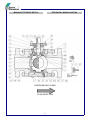
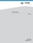
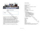
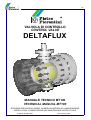
I-E
VALVOLA DI CONTROLLO
CONTROL VALVE
DELTAFLUX
MANUALE TECNICO MT100
TECHNICAL MANUAL MT100
ISTRUZIONI PER L’INSTALLAZIONE, LA MESSA IN SERVIZIO E LA MANUTENZIONE
INSTALLATION, COMMISSIONING AND MAINTENANCE INSTRUCTIONS
Edizione Gennaio 2002
Issue January 2002
MANUALE TECNICO MT100
TECHNICAL MANUAL MT100
AVVERTENZE
PRECAUTIONS
AVVERTENZE GENERALI
GENERAL PRECAUTIONS
- L’apparecchiatura descritta in questo manuale è un
dispositivo soggetto a pressione inserito in sistemi
pressurizzati;
- l’apparecchiatura in questione è normalmente inserita
in sistemi che trasportano gas infiammabili (ad
esempio gas naturale).
- The apparatus described in this manual is a device
subject to pressure installed in systems under
pressure;
- the apparatus in question is normally installed in
systems for transporting flammable gases (natural gas,
for example).
AVVERTENZE PER GLI OPERATORI
PRECAUTIONS FOR THE OPERATORS
Prima di procedere all’installazione, messa in servizio
o manutenzione gli operatori devono:
- prendere visione delle disposizioni di sicurezza
applicabili all’installazione i n cui devono operare;
- ottenere le necessarie autorizzazioni ad operare
quando richieste;
- dotarsi delle necessarie protezioni individuali (casco,
occhiali, ecc.);
- assicurarsi che l’area in cui si deve operare sia dota ta delle protezioni collettive previste e delle necessarie indicazioni di sicurezza.
Before proceeding with installation, commissioning or
maintenance, operators must:
- examine the safety provisions applicable to the
installation in which they must work;
- obtain the authorisations necessary for working when
so required;
- use the necessary means of individual protection
(helmet, goggles, etc.);
- ensure that the area in which they operate is fitted
with the means of collective protection envisaged and
with the necessary safety indications.
MOVIMENTAZIONE
HANDLING
La movimentazione dell’apparecchiatura e dei suoi
componenti deve essere eseguita dopo aver valutato
che i mezzi di sollevamento siano adeguati ai carichi
da sollevare (capacità di sollevamento e funzionalità).
La movimentazione dell’apparecchiatura deve essere
eseguita utilizzando i punti di sollevamento previsti
sull’apparecchiatura stessa.
L’impiego di mezzi motorizzati è riservato al personale
a ciò preposto.
The handling of the apparatus and of its components
must only be carried out after ensuring that the lifting
gear is adequate for the loads to lift (lifting capacity
and functionality). The apparatus must be handled
using the lifting points provided on the apparatus itself.
Motorised means must only be used by the persons in
charge of them.
INSTALLAZIONE
INSTALLATION
Qualora l’installazione dell’apparecchiatura richieda
l’applicazione in campo di raccordi a compressione,
questi devono essere installati seguendo le istruzioni
del produttore dei raccordi stessi. La scelta del raccordo deve essere compatibile con l’impiego specificato
per l’apparecchiatura e con le specifiche di impianto
quando previste.
If the installation of the apparatus requires the
application of compression fittings in the field, these
must be installed following the instructions of the
manufacturer of the fittings themselves. The choice of
the fitting must be compatible with the use specified for
the apparatus and with the specifications of the system
when envisaged.
MESSA IN SERVIZIO
COMMISSIONING
La messa in servizio deve essere eseguita da
personale adeguatamente preparato.
Durante le attività di messa in servizio il personale non
strettamente necessario deve essere allontanato e
deve essere adeguatamente segnalata l’area di
interdizione (cartelli, transenne, ecc.).
Verificare che le caratteristiche dell’apparecchiatura
siano quelle richieste.
Durante la messa in servizio devono essere valutati i
rischi determinati da eventuali scarichi in atmosfera di
gas infiammabili o nocivi.
Per installazione su reti di distribuzione per gas naturale occorre considerare il rischio di formazioni di
miscela esplosiva (gas/aria) all’interno delle tubazioni.
Commissioning must be carried out by adequately
trained personnel.
During the commissioning activities, the personnel not
strictly necessary must be ordered away and the no-go
area must be properly signalled (signs, barriers, etc.).
Check that the features of the apparatus are those
requested.
When commissioning, the risks associated with any
discharges into the atmosphere of flammable or
noxious gases must be assessed.
In installations in natural gas distribution networks, the
risk of the formation of explosive mixtures (gas/air)
inside the piping must be considered.
2
MANUALE TECNICO MT100
TECHNICAL MANUAL MT100
INDICE
INDEX
CARATTERISTICHE
PAGINA 4
MAIN FEATURES
PAGE 4
1 INSTALLAZIONE DELLA VALVOLA
9
1 VALVE INSTALLATION
9
2 SOSTITUZIONE DELL’ANELLO DI GRAFITE
9
2 SUBSTITUTION OF THE FIRE-SAFE RING
9
2.1 SOSTITUZIONE DELL’ANELLO DI GRAFITE
9
2.1 SUBSTITUTION OF THE FIRE-SAFE RING
9
2.2 SOSTITUZIONE DELL’ANELLO DI GRAFITE
10
2.2 SUBSTITUTION OF THE FIRE-SAFE RING
10
2.3 SOSTITUZIONE DELL’ANELLO DI GRAFITE
10
2.3 SUBSTITUTION OF THE FIRE-SAFE RING
10
2.4 SOSTITUZIONE DELL’O-RING
11
2.4 SUBSTITUTION OF THE O-RING
11
3 SOSTITUZIONE DELLA SEDE E GUARNIZIONE
11
3 SUBSTITUTION OF THE SEAT AND GASKET
11
4 SOSTITUZIONE DELL’O-RING SULLO STELO
12
4 SUBSTITUTION OF THE STEAM O-RING
12
5 LUBRIFICAZIONE
13
5 GENERAL LUBRIFICATION
13
6 LISTA DEI RICAMBI CONSIGLIATI
14
6 RECOMMENDED SPARES
14
3
MANUALE TECNICO MT100
TECHNICAL MANUAL MT100
CARATTERISTICHE
GENERAL
La Pietro Fiorentini mette a disposizione del cliente
una gamma completa di valvole di regolazione in
grado di fornire la soluzione ottimale per qualsiasi
problema od applicazione.
La necessità di trasportare rilevanti portate con minime
cadute di pressione localizzate sulla valvola di
regolazione, richiede la combinazione di ampia
capacità ed elevata rangeability.
Questa combinazione è tipica della configurazione di
una valvola a sfera.
La valvola a sfera offre il più elevato rapporto
Cv/diametro.
Questo si traduce in minori dimensioni d’ingombro
della valvola e dell’impianto, configurazioni più semplici
del piping, facilità di installazione e manutenzione.
Le speciali configurazioni dei trim della valvola
DELTAFLUX consentono un’elevata rangeability,
un’eccellente tenuta, l’abbattimento del rumore e una
riduzione del fenomeno di cavitazione.
Pietro Fiorentini provides complete control ball valve
units to solve any customer problems and applications.
STELO ANTIESPULSIONE
BLOW OUT PROOF STEM
Lo stelo si può montare solo dalla parte interna della
valvola. Un robusto collare lo trattiene all’interno del
corpo. Questa soluzione permette di sostituire la
guarnizione esterna sullo stelo qualora venga
danneggiata.
The stem can be assembled only from the nternal side
of the valve. A stout collar eeps it inside the body. This
solution llows to replace the outside gasket on he stern
in case it is damaged.
The need to transfer large volumetric flows with
minimal pressure drop located over the control valve
calls for a combination of high capacity and
rangeability.
This combination is inherent in ball valve design.
Quarter-turn ball valve constructions have the highest
possible Cv/size ratio.
This means smaller external valve dimensions,
compact valve solutions, simple pipe configurations,
light and easy installation.
The special trims design of DELTAFLUX provides high
rangeability, excellent tightness and source treatment
for noise and cavitation.
METAL TO METAL SEAT
TENUTA METALLO SU METALLO
PROGETTAZIONE DEL TRIM
PER IL FLUIDO DA REGOLARE
SPECIFIC
TRIM
APPLICATIONS
ADATTO
SUITABLE FOR
APPLICATIONS
ADATTA PER APPLICAZIONI CON GAS E
LIQUIDI
FOR
GAS
DIFFERENT
AND
LIQUID
REPLACEABLE TRIM
TRIM SOSTITUIBILE
NON CLOGGING, SELF CLEANING AND
FLUSHING
POCO SOGGETTA AD INTASAMENTI,
POCO SENSIBILE ALLO SPORCO E AI
FLUIDI CARICHI
4
MANUALE TECNICO MT100
TECHNICAL MANUAL MT100
AMPIA VARIABILITÀ DI ATTUATORI
APPLICABILI
WIDE RANGE OF ACTUATOR TYPE
AMPIA VARIABILITÀ DI CONTROLLORI
UTILIZZABILI
WIDE RANGE OF CONTROLLERS TYPE
ELIMINAZIONE DELLA CAVITAZIONE
CAVITATION AND VIBRATION FREE
SFERA IMPERNIATA
TRUNNION MOUNTED BALL
OTTIMA TENUTA CON VALVOLA CHIUSA
GOOD TIGHTNESS WITH VALVE CLOSED
BASSE PERDITE DI CARICO
LOW PRESSURE DROP
ALTA AFFIDABILITÀ
HIGH RELIABILITY
COSTRUZIONE CONFORME ALLE
NORME ASTM - ASME - NACE - API -ANSI
CONSTRUCTION ACCORDING TO
STANDARD ASTM ASME - NACE - API -ANSI
CLASSE: 150 - 300 - 400 - 600 -900
DIAMETRI NOMINALI: 2'' A 24"
PRESSURE CLASSES: 150 - 300 - 400 600 - 900
VALVE SIZE: DN 2'' TO 24"
PASSAGGIO TOTALE O RIDOTTO
FULL BORE AND REDUCED BORE
TIPO DI ESTREMITÀ: RAISED FACES OR
RING JOINT OR WELDING ENDS
ENDS: RAISED FACES OR RING JOINT
OR WELDING ENDS
5
MANUALE TECNICO MT100
TECHNICAL MANUAL MT100
DIREZIONE DEL FLUSSO
FLOW DIRECTION
6
MANUALE TECNICO MT100
TECHNICAL MANUAL MT100
7
MANUALE TECNICO MT100
CORPO
SEDE
SFERA
STELO
COPERCHIO SUPERIORE
O-RING
TIRANTE FILETTATO
DADO
CUSCINETTO REGGISPINTA
VITE
COPERCHIO INFERIORE
TAPPO
VITE
O-RING
VITE
MOLLA
O-RING
CUSCINETTO
CUSCINETTO
O-RING
IMBOCCO MONTE
IMBOCCO VALLE
VITE
CUSCINETTO STELO
FLANGIA COMANDO
O-RING
SPINA
O-RING (O ANELLO DI GRAFITE POS. 58)
ANELLO DI CENTRAGGIO
INGRASSATORE
ANELLO SFERA
VITE
O-RING
TARGHETTA INDICE FLUSSO
GUARNIZIONE METALLO
CALOTTA SFERICA
ANELLO ELASTICO
PORTA ANELLI MONTE
PORTA ANELLI VALLE
TECHNICAL MANUAL MT100
1
2
3
4
5
6
7
8
9
10
12
14
15
17
18
20
21
22
23
24
26
26
28
31
34
38
44
45
50
62
174
175
177
244
252
294
295
296
298
8
BODY
SEAT
BALL
STEM
BONNET UP
O-RING
STUD BOLT
NUT
THRUST BEARING
CAP SCREW
BONNET LOW
PLUG
CAP SCREW
O-RING
CAP SCREW
SPRING
O-RING
THRUST BEARING
THRUST BEARING
O-RING
INLET TAIL PIECE
OUTLET TAIL PIECE
CAP SCREW
THRUST BEARING
ACTUATOR FLANGE
O-RING
PIN
O-RING (OR GRAPHITE RING POS. 58)
CENTERING RING
GREASE NIPPLE
RETAINING RING
CAP SCREW
O-RING
DIRECTION FLOW PLATE
METAL GASKET
CALOTTE
ELASTIC RING
INLET HOLDER RING
OUTLET HOLDER RING
MANUALE TECNICO MT100
TECHNICAL MANUAL MT100
1. INSTALLAZIONE DELLA VALVOLA
1 VALVE INSTALLATION
1.1 Rimuovere le protezioni dagli imbocchi.
1.2 Ispezionare l’interno della valvola, verificare che
sia pulito e senza corpi estranei; la valvola viene
spedita con le estremità chiuse da protezioni,
tuttavia durante li trasporto materiali estranei
possono essere introdotti nel foro di passaggio.
La presenza di corpi estranei tra la sede e la
sfera può danneggiare la superficie di tenuta.
1.3 Aprire e chiudere la valvola per verificare che
funzioni correttamente.
1.4 Prima di installare la valvola sulla tubazione pulire
accuratamente l’interno della tubazione stessa.
1.5 Installare la valvola sulla tubazione rispettando
l’indicazione della direzione di flusso
LA VALVOLA NON È BIDIREZIONALE.
1.1 Remove on the end connection the protection
caps.
1.2 Inspect the valve bore for foreign parts and clean if
necessary. Valve are shipped with ends sealed,
but during the transit some foreign material may
be introduced into the valve bore. The presence
of foreign parts between the seat and the ball
could damage the seat thigtness facing.
1.3 Open and close the valve completely in order to
check the right operability.
1.4 Before installation of the valve on the pipeline
provide for cleaning it.
1.5 Install the valve on the line; respecting the valve
flow direction.
THE VALVE IS NOT BI-DIRECTIONAL.
2 SOSTITUZIONE DELL’ ANELLO DI
GRAFITE (58) OPPURE DELL’O-RING (56)
2 SUBSTITUTION OF THE GRAPHITE
RING (58) OR THE O-RING (56)
Le operazioni sottoscritte possono essere effettuate
senza rimuovere la valvola dalla linea.
Verificare che la valvola sia completamente chiusa
(o aperta). Scaricare la pressione dalla linea
lasciando aperto il tappo (14).
This maintenance operation can be performed without
removing the valve from the line.
Check that the valve are in fully closed (or open)
position. Bleed off line pressure leaving plug (14)
open.
2.1 SOSTITUZIONE DELL’ ANELLO DI
GRAFITE (58) PER DN 2" - 4" CLASSE 150
- 300 E DN 2" - 3" CLASSE 600 CON LEVA
2.1 SUBSTITUTION THE GRAPHITE RING
(58) FOR ND 2" - 4" CLASS 150 - 300 AND
ND 2" - 3" CLASS 600 WITH LEVER
2.1.1 Svitare il dado (52), togliere la rosetta (75), il
mozzo leva (74), il dado (48), la molla a tazza
(49), il fermo stelo (66), la seconda molla a tazza
(49), l’anello di centraggio (50) l’anello di grafite
(45).
2.1.2 Pulire e lubrificare la sede dell’anello di grafite,
assemblare la nuovo anello di grafite (45) e
l’anello di centraggio (50).
2.1.3 Assemblare la molla a tazza (49), il fermo stelo
(66), la seconda molla a tazza (49),il dado (48),
il mozzo leva (74), la rosetta (75), il dado (52) e
fissarlo.
2.1.1 Loosen the nut (52), remove the washer (75), the
wrench head (74), the nut (48), the spring
washer (49), the stem stop (66), the second
spring washer (49), the centering ring (50) and
the graphite ring (45).
2.1.2 Clean and lubricate the graphite ring groove,
assemble the new graphite ring (45) and the
centering ring (50).
2.1.3 Assembly the spring washer (49), the stem stop
(66), the second spring washer (49), the nut
(48), the wrench head (74), the washer (75), the
nut (52) and retaining it.
9
MANUALE TECNICO MT100
TECHNICAL MANUAL MT100
2.2 SOSTITUZIONE DELL’ ANELLO DI
GRAFITE (58) PER DN 6" CLASSE 150 300 CON LEVA
2.2 SUBSTITUTION THE OR GRAPHITE
RING (58) FOR DN 6" CLASS 150 - 300
WITH LEVER
2.2.1 Rimuovere la spina elastica (19) e il mozzo leva
(74); svitare il dado (48), togliere la molla a tazza
(49), il fermo stelo (66) e la seconda molla a
tazza (49).
2.2.2 Togliere l’anello di centraggio (50) e l’anello di
grafite (58).
2.2.3 Pulire e lubrificare la sede dell’anello di grafite,
assemblare la nuovo anello di grafite (58) il
l’anello di centraggio (50), la molla a tazza (49),
il fermo stelo (66), la seconda molla a tazza (49),
il dado (48), il mozzo leva (74) e la spina elastica
(19).
2.2.1 Remove the elastic pin (19) and the wrench head
(74); unscrew the nut (48), remove the spring
washer (49), the stem stop (66) and the second
spring washer (49).
2.2.2 Remove the centering ring (50) and the graphite
ring (58).
2.2.3 Clean and lubricate the graphite ring groove,
assembly the new graphite ring (58) the
centering ring (50), the spring washer (49), the
stem stop (66), the second spring washer (49),
the nut (48), the wrench head (74) and the
elastic pin (19).
2.3 SOSTITUZIONE DELL’ ANELLO DI
GRAFITE (58) PER DN 2" - 6" CLASSE 150
- 300 E DN 2" - 3" CLASSE 600 CON
COMANDO MANUALE
2.3 SUBSTITUTION THE GRAPHITE (58)
FOR DN 2" - 6" CLASS 150 - 300 AND DN
2" - 3" CLASS 600 WITH GEAR
OPERATOR
2.3.1 Svitare le viti (10) e togliere il comando.
2.3.1 Unscrew the screws (10) and remove the gear
operator.
2.3.2 Unscrew the screws (15) remove the flange (34),
the centering ring (50) and the graphite ring (58).
2.3.3 Clean and lubricate the graphite ring groove.
Assembly the new graphite ring (58), assembly
the centering ring (50), the flange (34) and retightening the screws (15).
2.3.4 Assembly the gear operator and re-tightening the
screws (10).
2.3.2 Svitare le viti (15) togliere la flangia (34), l’anello
di centraggio (50) e l’anello di grafite (58).
2.3.3 Pulire e lubrificare la sede dell’anello di grafite,
assemblare la nuovo anello di grafite (58) il
l’anello di centraggio (50), la flangia (34) e
serrare le viti (15).
2.3.4 Riposizionare il comando e serrare le viti (10).
* Si suggerisce di contrassegnare la posizione del
comando prima della rimozione e di riassemblarlo nella
stessa posizione. Nel caso di attuatore ricordare di
regolare i fermi. Eventualmente vedere la
documentazione dell’attuatore.
* Is suggested to sign the position of the gear operator
before remove it and reassemble it on the same
position. In case of actuator remember too regulate the
limits
stops.
Eventually
see
the
actuator
documentation.
10
MANUALE TECNICO MT100
TECHNICAL MANUAL MT100
2.4 SOSTITUZIONE DELL’O-RING (56) O
DELL’ ANELLO DI GRAFITE (58) PER DN
8" - 14" CLASSE 150 - 300 E 4" - 12"
CLASSE 600 CON COMANDO MANUALE
2.4 SUBSTITUTION THE O-RING (56) OR
GRAPHITE (58) FOR DN 8" - 14" CLASS
150 - 300 AND DN 4" - 12" CLASS 600
WITH GEAR OPERATOR
2.4.1 Svitare le viti (35) e togliere il comando con la
flangia (34).
2.4.2 Togliere la linguetta (11), l’anello di centraggio
(50) e l'O-Ring (56) (o il anello di grafite (58).
2.4.3 Pulire e lubrificare la sede dell’O-Ring (56).
Sostituire l’O-Ring (56) (o il anello di grafite (58),
e assemblare l’anello di centraggio (50).
2.4.4 Posizionare la flangia (34) con il comando e
serrare le viti (35).
2.4.1 Unscrew the screws (35) and remove the gear
operator with the flange (34).
2.4.2 Remove the stem key (11), the centering ring
(50) and the O-Ring (56) (or graphite ring (58)).
2.4.3 Clean and lubricate the O-Ring groove.
Assembly the new O-Ring (56) (or graphite ring
(58)), assembly the centering ring (50).
2.4.4 Assembly the flange (34) with the gear operator
and retightening the screws (35).
* Si suggerisce di contrassegnare la posizione del
comando prima della rimozione e di riassemblarlo nella
stessa posizione. Nel caso di attuatore ricordare di
regolare i fermi. Eventualmente vedere la
documentazione dell’attuatore.
* Is suggested to sign the position of the gear operator
before remove it and reassemble it on the same
position. In case of actuator remember too regulate the
limits
stops.
Eventually
see
the
actuator
documentation.
3 SOSTITUZIONE DELLA SEDE (2) E
DELLA GUARNIZIONE (252)
3 SUBSTITUTION OF SEAT (2) AND
GASKET (252)
3.1.1 Portare la valvola in posizione di chiusura e
scaricare la pressione dalla tubazione.
3.1.1 Turn the valve to fully closed position and bleed
off the pressure of the line (upstream and
downstream).
3.1.2 Take off the valve from the line and place it over
with inlet tail piece (26) on the top.
3.1.2
Rimuovere la valvola dalla tubazione e
posizionarla sul banco di lavoro con l’imbocco di
monte (26) rivolto verso l’alto.
3.1.3 Rimuovere i dadi (8).
3.1.4 Rimuovere l’imbocco (26); è possibile ora
rimuovere la sede (2) con le molle (20) e l'ORing (6); pulire e lubrificare la sede del seggio
nell’imbocco.
3.1.5 Pulire e lubrificare la nuova sede (20) e la sede
dell’O-Ring. Montare il nuovo O-Ring (6).
3.1.6 Rimuovere le viti (175), l’anello sfera (174), l’ORing (177) e la guarnizione (252); pulire e
lubrificare la sede dell’O-Ring. Montare il nuovo
O-Ring (177), la nuova guarnizione (252) sulla
sfera, l’anello sfera (174) e le viti (175).
3.1.7 Per facilitare l’inserimento della nuova sede (2)
con gli O-Ring (17) operare come di seguito
descritto:
- montare le molle (20) con del grasso nelle
relative sedi;
- posizionare la sede (2) sull’imbocco (26);
- inserire l’imbocco (26) sui tiranti (7) in modo
che l’imbocco stesso si inserisca sul corpo (1).
3.1.3 Loosen the nuts (8).
3.1.4 Remove the tail piece (26), now is possible
remove the seat (2) with the springs (20), the ORing (6); clean and lubricate the seat poket.
3.1.5 Clean and lubricate the new seat (20) and the
O-Ring groove. Assembly the new O-Ring (6).
3.1.6 Remove cap screw (175), the retaining ring
(174), the O-Ring (177) and the gasket (252);
clean and lubricate the O-Ring groove. Install
new O-Ring (177), new gasket (252) on the ball,
the retaining ring (174) and the cap screw (175).
3.1.7 In order to make easier insertion of new seat (2)
with the O-Rings (17) do as follows:
- assemble the springs (20) with the grease into
the relevant sid;,
- insert the seat (2) in to the tailpiece (26);
- Insert the tail piece (26) into the stud bolts (7)
in such way that the tail piece enters in the
body (1).
3.1.8 At the same time gradually tighten the nuts (8).
3.1.8 Stringere gradualmente e uniformemente i dadi
(8).
* La pulitura può essere eseguita con un panno
morbido im bevuti di soluzione di petrolio
* Cleaning can be carryout with a soft cloth in an oil
solution.
11
MANUALE TECNICO MT100
TECHNICAL MANUAL MT100
4 SOSTITUZIONE DELL’O-RING (21)
SULLO STELO, I REGGISPINTA (9) E (31)
E I CUSCINETTI (22) (23)
4 SUBSTITUTION OF O-RING (21) ON THE
STEM, THRUST PLATE (9) (31) AND
BEARING (22) (23)
4.1.1 Eseguire le azioni indicate al punto 3.1.1; ai punti
2.1.1 o 2.2.1,2.2.2 o 2.3.1,2.3.2 oppure 2.4.1,
2.4.2 in base alle versioni da revisionare.
4.1.2 Togliere le viti (18) e rimuovere il coperchio (5).
4.1.9 Montare il coperchio superiore (5) sul corpo e
fissare le viti (18).
4.1.10 Allentare le viti (28), rimuovere il coperchio
inferiore (12), l’O-Ring (24), il cuscinetto inferiore
(23) e il reggispinta (9).
4.1.11 Pulire e lubrificare la sede dell’O-Ring, montare
il nuovo O-Ring, il cuscinetto inferiore(23), il
reggispinta (9) e lubrificare con grasso.
4.1.12 Montare il coperchio inferiore (12) nel corpo e
fissare le viti (28).
4.1.13 Eseguire le azioni indicate ai punti 2.1.3 o 2.2.3
o 2.3.3 oppure 2.4.3.
4.1.14 Controllare la tenuta della sede e azionare la
valvola per verificarne il corretto funzionamento.
4.1.1 Carry out the same steps as indicate at point
3.1.1, at point 2.2.1, 2.2.2 or 2.3.1, 2.3.2 or
2.4.1, 2.4.2
4.1.2 Loosen the screws (18)and remove the upper
bonnet (5).
4.1.3 Remove the stem (4) from internal side of
bonnet.
4.1.4 Remove the O-Rings (21) (38), clean and
lubricate with light oil, assemble the new O-Ring
(21) (38)
4.1.5 Substitute the thrust bearing (9) (31) and the
upper bearing (22).
4.1.6 Assembly the upper bearing (22) into the bonnet
(5), the thrust bearing (31) onto the stem (4) and
the thrust bearing (9) on to hub of ball.
4.1.7 After smearing with a thin layer of light oil
assembly the stem (4) from internal side of
bonnet.
4.1.8 Place the stem (4) with the connecting planes to
ball enters into relative planes of hub ball or in
the thrust bushing (32) of the ball.
4.1.9 Assemble the bonnet (5) into the body and fix the
screws (18).
4.1.10 Loosen the screw (28), remove the lower
bonnet (12), the O-Ring (24) and the lower
bearing (23) and thrust bearing (9).
4.1.11 Clean and lubricate th e O-Ring groove,
assembly the new O-Ring, the new bearing the
thrust bearing (9); lubricate with light oil.
4.1.12 Assemble the lower bonnet (12) into body and
fix the screws (28).
4.1.13 Carry out the same steps as indicated on point
2.1.3 or 2.2.3 or 2.3.3 or 2.4.3
4.1.14 Check the seal tightness and operate the valve
in order to verify the right functionally.
5 LUBRIFICAZIONE
5 GENERAL RUBRICATE
Per lubrificare tutte le parti della valvola è consigliato
l’uso di TECNOLUBE SEAL POLYMER 1000
oppure lubrificanti con prestazioni similari.
For lubricate all the components of the valve during the
assembly is suggested the use of TECNOLUBE
SEAL POLYMER 1000 or similarequivalent see
relative data sheet.
4.1.3 Togliere lo stelo (4) dalla parte interna del
coperchio superiore.
4.1.4 Rimuovere gli O-Ring (21) (38), pulire e
lubrificare la sede e assemblare i nuovi O-Ring
(21) (38).
4.1.5 Sostituire il reggispinta (9) (31) e il cuscinetto
superiore (22).
4.1.6 Montare il cuscinetto superiore (22) sul coperchio
(5), il reggispinta (31) sullo stelo (4), ed il
reggispinta (9) sul mozzo della sfera.
4.1.7 Dopo aver lubrificato con un leggero velo di
grasso, infilare lo stelo (4) dalla parte interna del
coperchio.
4.1.8 Posizionare lo stelo (4) con le facce parallele
accoppiate alle bussole (32) della sfera.
12
MANUALE TECNICO MT100
6
TECHNICAL MANUAL MT100
LISTA DEI RICAMBI CONSIGLIATI
6
RECOMMENDED SPARES
- FIG. 230 PASSAGGIO TOTALE
CLASSE 150 – 300 - 600
- FIG. 230 FULL BORE
CLASS 150 – 300 - 600
- FIG. 260 PASSAGGIO RIDOTTO
CLASSE 150 – 300 - 600
- FIG. 260 REDUCE BORE
CLASS 150 – 300 - 600
13
MANUALE TECNICO MT100
POS.
ITEM
2
6
9
17
21
22
23
24
31
38
56
177
252
TECHNICAL MANUAL MT100
DESCRIZIONE
DESCRIPTION
Sede
Seat
O-Ring
Cuscinetto reggispinta
Thrust bearing
O-Ring
O-Ring
Cuscinetto superiore
Upper bearing
Cuscinetto inferiore
Lower bearing
O-Ring
Cuscinetto reggispinta
Thrust bearing
O-Ring
O-Ring
O-Ring
Guarnizione
Gasket
14
N. PEZZI
PIECES NR.
1
2
2
1
2
1
1
1
1
1
1
1
MANUALE TECNICO MT100
TECHNICAL MANUAL MT100
PER L’ORDINAZIONE DEI RICAMBI PRECISARE
WHENORDERINGSPAREPARTS,PLEASESPECIFY
Tipo di valvola
Type of valve
Dn (diametro nominale )
Dn (nominal diameter)
Classe (150-300-400-600-900-1500)
Class (150-300-400-600-900-1500)
N. di Fabbrica (Matricola)
Serial no. (Serial no.)
Anno di costruzione
Year of manufacture
Tipo di fluido impiegato
Type of fluid used
Il n. del particolare (posizione)
The no. of the part (position no.)
Quantità desiderata
Quantity desired
NOTE
NOTES
15
MANUALE TECNICO MT100
TECHNICAL MANUAL MT100
I dati sono indicativi e non impegnativi. Ci riserviamo di apportare eventuali modifiche senza preavviso.
The data are not binding. We reserve the right to make modifications without prior notice.
Pietro Fiorentini
S.p.A.
UFFICI COMMERCIALI:
OFFICES:
I-20124 MILANO Italy - Via Rosellini, 1 - Phone +39.02.6961421 (10 linee a.r.) - Telefax +39.02.6880457
E-mail: [email protected]
I-36057 ARCUGNANO (VI) Italy - Via E. Fermi, 8/10 - Phone +39.0444.968511 (10 linee a.r.) - Telefax +39.0444.960468
E-mail: [email protected]
I-80142 NAPOLI Italy - Via B. Brin, 69 - Phone +39.081.5544308 - +39.081.5537201 - Telefax +39.081.5544568
E-mail: [email protected]
ASSISTENZA POST-VENDITA E SERVIZIO RICAMBI:
SPARE PARTS AND AFTER-SALES SERVICE:
I-36057 ARCUGNANO (VI) - Italy - Via E. Fermi, 8/10 - Phone +39.0444.968511 (10 linee a.r.) - Telefax +39.0444.968513 - E-mail: [email protected]
16