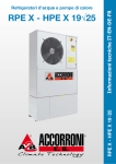
Download RT-AD 182÷804
Transcript
R22 R407c A I R C O N D I T I O N I N G R410a MTE01131D0005-00 - 3-12 Sostituisce/Supersade Ersetzt/Remplace/ Remplaza UNITÉS DE TOITURE À DOBLE PANNEAU SANDWICH AVEC COMPRESSEURS SCROLL DE 58 kW A 252 kW RT-AD 182÷804 Sandwich Doppelpaneel HAUSDACH Einheiten mit Scroll VERDICHTERN von 58 kW bis 252 kW Catalogo/Catalogue/Katalog/Catalogue/ Catálogo DOUBLE PANELS SANDWICH TYPE ROOF TOP WITH SCROLL COMPRESSORS FROM 58 kW TO 252 kW Serie/Series/Serie/Série/Serie ROOF TOP A DOPPIA PANNELLATURA SANDWICH CON COMPRESSORI SCROLL DA 58 kW A 252 kW Emissione/Issue Ausgabe/Emission MANUALE TECNICO TECHNICAL MANUAL technisches Handbuch manuel technique MANUAL TECNICO R134a F18 RT-AD 182÷804 2 RT-AD 182÷804 INDICE Pag. INDEX Pag. • Descrizione generale 4 • General description 4 • Versioni sezione motocondensante 4 • Condensing section versions 4 • Versioni sezione trattamento aria 4 • Air handling section versions 4 • Sezioni aggiuntive 4 • Complementary sections 4 • Caratteristiche costruttive 6 • Constructional characteristics 6 • Accessori montati in fabbrica 6 • Factory fitted accessories 6 • Accessori forniti separatamente 8 • Loose accessories 8 • Condizioni di riferimento 8 • Reference conditions 8 8 • Operating range • Limiti di funzionamento 8 • Dati tecnici 10 • Technical data 10 • Rese in raffreddamento 12 • Cooling capacity 12 • Rese in riscaldamento 14 • Heating capacity 14 • Schema circuito frigorifero: • Refrigeration circuit diagram: Unità per solo raffreddamento 16 Only cooling units Unità a pompa di calore 17 Heat pump units • Composizioni standard 18-25 • Standard compositions 16 17 18-25 • Dati tecnici umidificatori 26 • Endothermic humidifiers technical data 26 • Dati tecnici generatori d'aria calda 26 • Thechnical features hot air generators 26 • Rese batteria acqua calda 27 • Heating water coil capacity 27 • Pressione sonora 27 • Sound pressure level 27 • Perdite di carico batteria acqua calda 28 • Hot water coil pressure drops 28 • Sistema di regolazione con microprocessore 30 • Microprocessor control system 30 • Legenda schemi circuiti elettrici 31 • Wiring diagrams explanation • Schemi circuiti elettrici INDEX 32-39 Seite • Wiring diagrams INDEX 31 32-39 Pag. • Allgemeine Beschreibung 5 • Description generale 5 • Verflüssigungssektion Ausführungen 5 • Versions sections de condensation 5 • Lüftung Sektion Ausführungen 5 • Versions sections traitement d'air • Zusätzliche sektionen 5 • Section additionnelles • Konstruktionsmerkmale 7 • Caracteristiques de construction 7 • Im Werk montiertes Zubehör 7 • Accessoires montés en usine 7 • Lose mitgelieferten Zubehöre 9 • Accessoires fournis separement 9 • Richtwerte Bedingungen am Gerätestandort 9 • Conditions de référence 9 • Einsatzbereich 9 • Limites de fonctionnement 5 55 9 • Technische daten 11 • Données techniques 11 • Kälteleistungen 12 • Puissance frigorifique 12 • Heizleistungen 14 • Puissance calorifique 14 • Schema du circuit frigorifique: • Kältekreislaufschema: Einheit nür Kühlung 16 Groupe de production d’eau glacée Einheit nür Wärmepumpe 17 Unité à pompe à chaleur • Standard Zusammensetzung 18-25 • Composition standard 16 17 18-25 • Technische Daten Luftbefeuchter 26 • Donées techniques humidificateurs 26 • Technische Daten der Warme Luft Erzeuger 26 • Donées techniques generateurs d'air chaud 26 • Stung warmwasserheizregister 27 • Puissance batterie eau chaude 27 • Schalldruckpegel 27 • Niveaux de pression sonore 27 • Druckverluste warmwasserheizregister 29 • Pertes de charge batterie eau chaude 29 • Funktion und ausstattung der Mikroprozessorregelungen 30 • Systeme de réglage avec microprocesseur 30 • Schaltpläne Erklärung 31 • Explication de le diagrammes • Schaltpläne 32-39 • Diagrammes électriques 31 32-39 3 RT-AD 182÷804 DESCRIZIONE GENERALE GENERAL DESCRIPTION Condizionatori d’aria autonomi monoblocco per installazione esterna, da collegare ad una rete di canali per la distribuzione dell’aria. La gamma comprende 11 modelli da 58 a 252 kW, con portate aria da 2,7 a 12,3 m3/s. Self-contained air conditioners for outdoor installation, to be connected to duct system for air distribution. The range comprises 11 models from 58 to 252 kW with airflow from 2,7 to 12,3 m3/s. VERSIONI SEZIONE MOTOCONDENSANTE: RT-AD - Solo raffrescamento. Compressori. Scroll, ermetici, con spia livello olio. Sono dotati di protezione termica incorporata e di resistenza carter, e sono montati su supporti antivibranti in gomma. Ventilatori. Di tipo assiale direttamente accoppiati a motori trifase a rotore esterno. Una rete di protezione antinfortunistica è posta sull’uscita dell’aria. Condensatore. Costituito da una batteria (182÷363) o due batterie (393÷804) alettate con tubi in rame ed alette in alluminio. Le circuitazioni sul lato refrigerante sono realizzate in modo da ottenere un circuito nei modelli 182÷453 e due circuiti indipendenti nei modelli 524÷604. Evaporatore. Costituito da una batteria (182÷604) o due batterie (804) alettate con tubi in rame ed alette in alluminio. Le circuitazioni sul lato refrigerante sono realizzate in modo da ottenere un circuito nei modelli 182÷453 e due circuiti indipendenti nei modelli 524÷604. Circuito frigorifero: Realizzato in tubo di rame, comprende per tutti i modelli i seguenti componenti: valvola di espansione termostatica con equalizzazione esterna, filtro disidratatore, indicatore di liquido ed umidità e pressostati di alta e bassa pressione (a taratura fissa). RT-AD/WP - Pompa di calore reversibile. La versione a pompa di calore, oltre ai componenti della versione per solo raffreddamento, comprende per ogni circuito: valvola di inversione a 4 vie, valvole di ritegno e ricevitore di liquido. CONDENSING SECTION VERSIONS: RT-AD - Cooling only. Compressors. Scroll with oil sight glass. They are fitted with internal overheat protection and crankcase heater, installed on rubber shock absorbers. Fans. Axial fans directly coupled to a three-phase electric motor with external rotor. A safety fan guard is fitted on the air flow discharge. Condenser. From a (182÷363) or two (393÷804) copper tube and aluminium finned coils. Circuits on the refrigerant side are made to create one circuit in models 182÷453 and two independent circuits in models 524÷604. Evaporator. From a (182÷604) or two (804) copper tube and aluminium finned coils. Circuits on the refrigerant side are made to create one circuit in models 182÷453 and two independent circuits in models 524÷604. Refrigerant circuit. Produced in copper tubing, all models have the following components: electronic expansion valves, filter-drier, level and humidity indicator and high and low pressure switches (with fixed setting). RT-AD/WP - Reversible heat pump. The unit in heat pump version, in addition to the components of the only cooling unit, includes for each circuit: reverse valve, gate valve, and liquid receiver. VERSIONI SEZIONE TRATTAMENTO ARIA: Sezione base - Include: ventilatore di mandata centrifugo con motore elettrico completo di trasmissione regolabile, il tutto montato su supporti elastici, banco filtri piani a celle pieghettate (efficienza G4) e batteria di scambio termico, con tubi in rame ed alette di alluminio, posta su un’apposita vaschetta di raccolta condensa in acciaio inox. MS - Camera di miscela. Oltre ai componenti della sezione base, include: due serrande in alluminio a profilo alare, motorizzate da servomotori con ritorno a molla; il movimento contrapposto è garantito dalla trasmissioni di ingranaggi in nylon. ECO - Economizer. Oltre ai componenti della sezione base, include: ventilatore di ripresa con motore elettrico completo di trasmissione regolabile, montato su supporti elastici, e serrande in alluminio a profilo alare, motorizzate; le serrande sono a movimento contrapposto. Espulsione, ricircolo e rinnovo dell’aria sono gestiti tramite microprocessore presente sull’unità base; tale microprocessore, in funzione della temperatura dell’aria di ricircolo e di quella esterna, modula l’apertura delle serrande e gestisce le parzializzazioni di potenza del circuito frigorifero per garantire le condizioni di benessere dell’aria trattata. Le regolazioni della versione ECO sono gestite automaticamente sia in modalità free-cooling che free-heating. ECO/REC-FX - Recuperatore di calore a flussi incrociati. Oltre ai componenti della sezione base, include: recuperatore statico in alluminio con vasca di raccolta condensa, filtri piani ispezionabili attraverso porta incernierata e serrande con servomotori a ritorno a molla (serranda aria esterna + serranda ricircolo + serranda espulsione + 2 serrande free-cooling). Anche la regolazione di questa sezione è inclusa nella gestione del controllo macchina. AIR HANDLING SECTION VERSIONS: Basic section - Centrifugal supply fan with electrical motor complete of adjustable transmission mounted on elastic supports, flat filters with pleated cells (G4 efficiency); heat exchanger coil with copper pipes and aluminium fins placed on the stainless steel moisture drain pan. MS - Mixing box. Further to components of the basic section, includes: two wing profile aluminium dampers with spring return servomotors, the opposite movement is ensured by transmission of nylon gear. ECO - Economizer. Further to components of the basic section, includes: return air fan with electrical motor, complete of adjustable transmission, mounted on elastic supports; motorized wing profile aluminium dampers, the opposite movement is ensured by transmission of nylon gear. Supply, return and fresh air are controlled through the microprocessor fitted in the base unit; this microprocessor, according to the temperature of the return and fresh air, modulates the opening of the dampers and controls the refrigerant circuit capacity steps to ensure comfort conditions of the handled air. The adjustments of the ECO versions are automatically controlled both in free-cooling and free-heating mode. ECO/REC-FX - Cross flow heat recovery. Further to components of the basic section, includes: static recovery device made of aluminium with moisture drain pan, flat filters inspect able through hinged door and dampers with return spring servomotors (fresh air damper + return air damper + supply air damper + 2 free-cooling dampers). Also the adjustment of this section is included into the unit control. SEZIONI AGGIUNTIVE: UMI - Sezione con predisposizione per umidificatore. Include: camera del vapore, vasca di raccolta condensa in acciaio inox e predisposizione per l'inserimento delle lance di umidificazione; l’ispezione avviene tramite porta incernierata. Complementary sections: UMI - Section with preparation for Humidifier. Includes: the isothermal humidifier section comprises: steam room, stainless steel moisture drain pan and presetting for fitting the humidifying nozzles; hinged door in pressure for inspection. 4 RT-AD 182÷804 ALLGEMEINE BESCHREIBUNG DESCRIPTION GENERALE Kompakte Split-Kälteanlagen für Aussenaufstellung, zum Anschluß an Lüftungskanalnetz. Die Linie umfasst 11 Modelle von 58 bis 252 kW mit Luftmenge von 2,7 bis 12,3 m3/s. Conditionneurs d’air autonomes monobloc pour installation à l’extérieur, à relier à un réseau de gaines pour la distribution de l’air. La gamme comprend 11 modèles de 58 à 252 kW avec débit d’air de 2,7 à 12,3 m3/s. VERFLÜSSIGUNG SEKTION AUSFÜHRUNGEN RT-AD - nur Kühlung. Verdichter. Scroll mit Ölstandschauglas. Ausgestattet mit eingebautem Thermoschutzschalter, wenn nötig, montiert auf Gummidämpfungselementen. Gebläse. Schraubengebläse, direkt an Dreiphasenmotoren mit externem Läufer angeschlossen. Entlüftungsöffnung mit Schutzgitter. Verflüssiger. Bestehend aus einer (182÷363) oder zwei (393÷804) Wärmetauscheren mit rohre aus Kupfer mit aufgepressten Alu-Lamellen. Die Umläufe auf der Kühlseite, dass bei den Modellen 182÷453 ein Kreislauf auf der Kühlseite und bei den Modellen 524÷604 zwei unabhängige Kreisläufe erhalten werden. Verdampfer. Bestehend aus einer (182÷604) oder zwei (804)Wärmetauscheren mit rohre aus Kupfer mit aufgepressten Alu-Lamellen. Die Umläufe auf der Kühlseite, dass bei den Modellen 182÷453 ein Kreislauf auf der Kühlseite und bei den Modellen 524÷604 zwei unabhängige Kreisläufe erhalten werden. Kühlkreislauf. Kühlkreisläufe aus Kupferrohren, bei allen Modellen mit folgenden Komponenten: Expensionsventil elektronische, Filtertrockner, Flüssigkeit- und Feuchtigkeitsanzeiger und Hoch- und Niederdruckschalter (feste Einstellung). RT-AD/WP - umschaltbare Wärmepumpe. Neben den Komponenten der nur Kühlung Version, umfasst die Wärmepumpeversion für jeden Kreislauf: Wege Umschaltventil; Rückschlagventile Liquid Separator und Feuchtigkeit. VERSIONS SECTIONS DE CONDENSATION: RT-AD - Froid seul. Compresseur. Compresseurs Scroll comprenant voyant pour niveau de l’huile, protection thermique incorporée, resistance du carter, montés sur supports antivibrants en caoutchouc. Ventilateurs. De type axial, directement accouplés à des moteurs triphasés à rotor externe. Une grille de protection anti-accident est située sur la sortie d’air. Condenseur. D'un (182÷363) ou deux (393÷804) batteries en tuyaux de cuivre et ailettes en aluminium. Le système de circuits sur le côté réfrigérant est réalisé de manière à obtenir un circuit sur les modèles 182÷453 et deux circuits indépendants sur les modèles 524÷604. Evaporateur. D'un (182÷604) ou deux (804) batteries en tuyaux de cuivre et ailettes en aluminium. Le système de circuits sur le côté réfrigérant est réalisé de manière à obtenir un circuit sur les modèles 182÷453 et deux circuits indépendants sur les modèles 524÷604. Circuit frigorifique Réalisé en tuyau de cuivre, pour tous les modèles sont inclus les composants suivants: soupape d'expansion électroniques, filtre déshydrateur, voyant de liquide et d’humidité de pressotats de haute et basse pression (à calibrage fixe). RT-AD/WP - Pompe à chaleur réversible. La version à pompe à chaleur, en plus des composants de la version uniquement refroidissement, comprend pour chaque circuit: soupape d’inversion, vanne de retention, séparateur de liquide en aspiration. LÜFTUNG SEKTION AUSFÜHRUNGEN GRUNDSEKTION. Die Sektion enthält: Radial Auslassgebläse mit Elektromotor, komplett mit einstellbaren Getrieben, auf elastischen Befestigungen installiert, platte Filter Satz mit gebogenen Zellen (Wirkungsgrad G4); Wärmetauscher mit Kupferrohren und Aluminium Lamellen, montiert auf einem Kondensatbehälter aus Edelstahl. MS - Mischungssektion. Ausser der Komponenten der Hauptsektion enthält: zwei Aluminium Motor-betriebene Klappen mit Feder Verriegelung; die gegensätzliche Bewegung erfolgt durch das Nylon Getriebe System. ECO - Economizer. Ausser der Komponenten der Hauptsektion enthält: Rückluftventilator mit Elektromotor komplett mit einstellbarem Getriebe, auf elastischen Befestigungen montiert, und mit Motor-betriebenen Aluminium Klappen; die Klappen bewegen sich gegensätzlich. Ausblas, Rückluft und frische Luft Regelung erfolgt durch den auf der Einheit installierten Mikroprozessor; der Mikroprozessor nach der Rückluft und externer Luft Temperatur regelt das Öffnen der Klappen und leistet die Leistungsregelung des Kältekreises und den Wohlstand der behaldenten Luft. Die Regelungen der ECO Ausführung werden automatisch auch bei der Free Cooling und bei der Free Heating Funktionen geregelt. ECO/REC-FX - Wärmerückgewinnung mit durchgekreuzten Strömen. Ausser der Komponenten der Hauptsektion enthält: statische Wärmerückgewinnung aus Aluminium mit Kondensatwanne, platte Filter, durch abnehmbares Scharnierpanel kontrollierbar und Motorbetriebene Klappen mit Feder Verriegelung (externe Luft Klappe + Rücklauf Klappe + Abluft Klappe + 2 Free Cooling Klappen). Auch die Regelung dieser Sektion wird von der Einheit Regelung kontrolliert. VERSIONS SECTIONS TRAITEMENT D’AIR: Section de base. Ventilateur centrifuge de refoulement avec moteur électrique complet de transmission réglable, l’ensemble est monté sur supports élastiques ; ensemble de filtres plissés (efficacité G4); batterie d’échange thermique en tuyaux cuivre et ailettes aluminium, placée sur un bac à condensats en acier inox. MS - Chambre de mélange. Rajoutés à la section de base il y a: deux clapets en aluminium à profil de l’aile, motorisés par servomoteurs à retour à ressort ; le mouvement opposé est garanti par la transmission par engrenages en nylon. ECO - Economizer. Rajoutés à la section de base il y a: ventilateur de reprise avec moteur électrique complet de transmission réglable monté sur supports élastiques et clapets en aluminium à profil de l’aile, motorisés ; le mouvement opposé est garanti par la transmission par engrenages en nylon. Refoulement, reprise et air frais sont contrôlés par le microprocesseur de l’unité base : le microprocesseur, en fonction de la température de l’air de reprise et de l’air extérieur, module l’ouverture des clapets et contrôle les partialisations de puissance du circuit frigorifique pour garantir les conditions de bien-être de l’air traité. Les réglages de la version ECO sont gérés automatiquement soit en mode free-cooling qu’en mode free-heating. ECO/REC-FX - Récupérateur de chaleur à flux croisés. Rajoutés à la section de base il y a: récupérateur statique en aluminium et bac à condensats, filtres plats faciles à inspecter par la porte sur charnières et clapets avec servomoteurs à retour à ressort (clapet air extérieur + clapet reprise+clapet refoulement + 2 clapets free-cooling). Le réglage de cette section aussi est inclus dans la gestion du contrôle de la machine. ZUSÄTZLICHE SEKTIONEN: UMI - Abschnitt mit der Vorbereitung für Luftbefeuchter. Enthält: Dampfsektion; Kondensatwanne aus Edelstahl und Einrichtung für den Befeuchter, die Sektion ist durch abnehmbares Scharnierpanel kontrollierbar. Section additionnelles: UMI - Section à la préparation pour humidificateur. Inclut: chambre de la vapeur, bac à condensats en inox et prédisposition pour le montage des gicleurs d’humidification; l’inspection est possible par porte en pression sur charnières. 5 RT-AD 182÷804 UMI/EN - Sezione con umidificatore ad elettrodi immersi. Include: camera del vapore, vasca di raccolta condensa in acciaio inox e produttore di vapore ad elettrodi immersi; l’ispezione avviene attraverso porta incernierata. Il sistema è gestito e monitorizzato direttamente dal controllo macchina. F/CD - Generatore d’aria calda a condensazione con bruciatore a gas modulante. Include: camera di combustione a condensazione in acciaio inox. Il modulo termico a condensazione è progettato per l’inserimento nelle sezioni di trattamento aria e, sfruttando la tecnologia della premiscelazione e della modulazione, ottiene rendimenti molto elevati. La camera di combustione, per ottenere un’elevatissima resistenza alla condensa, è costruita in acciaio inox AISI 304L. Il bruciatore a gas premiscelato garantisce l’assenza di CO e le emissioni di azoto sono inferiori a 30 ppm. La scheda elettronica modula in modo continuo la portata termica in base ai parametri impostati e rilevati dal sistema di gestione e controllo dell’unità. UMI/EN - Section humidifier with electrodes immersed. Includes: steam room, stainless steel moisture drain pan and plunged electrodes steam producer; hinged door for inspection. The system is controlled and monitorized directly by the unit control. F/CD - Hot air generator with condensing modulating gas burner. Includes: condensation furnace in stainless steel. The condensation thermal module is designed to fit the air handling sections and, taking advantage of the premixing and modulation technology, achieves a very high efficiency. The furnace is made of AISI 304L stainless steel to ensure a very high resistance to the moisture. The premixed gas burner grants the absence of CO and nitrogen emissions are less than 30 ppm. The electronic card stepless modulates the heating capacity according to the parameters selected and detected by the control system of the unit. CARATTERISTICHE COSTRUTTIVE Struttura. Basamento perimetrale composto da elementi in lamiera zincata. Il telaio è realizzato con profili in lega di alluminio estruso uniti tramite giunti a 3 vie. L’assemblaggio del basamento e telaio è a doppio appoggio e garantisce la pedonabilità dei pannelli di fondo, la cui installazione avviene senza l’utilizzo di viti sporgenti. I pannelli del tipo sandwich di spessore 50 mm sono in lamiera preverniciata; la tenuta stagna è garantita da guarnizioni di battuta dotate di memoria di forma per una perfetta tenuta anche dopo ripetute rimozioni. L'unione delle sezioni avviene tramite staffe coniche di assemblaggio e la tenuta stagna è garantita da guarnizioni. Quadro elettrico. Include: interruttore generale con bloccoporta; fusibili; relè termici a protezione dei compressori; termocontatti per i ventilatori della sezione motocondensante; contattori per i motori dei ventilatori della sezione trattamento aria; relè di interfaccia; morsetti per collegamenti esterni. Microprocessore per la gestione automatica dell’unità. Permette di visualizzare in qualsiasi istante lo stato di funzionamento dell’unità e di controllare la temperatura dell’aria impostata e quella effettiva; nel caso di blocco parziale o totale dell’unità evidenzia quali sicurezze sono intervenute. CONSTRUCTION FEATURES Structure. Base perimeter made of steel sheet elements galvanised. The frame is made of extruded aluminium alloy profiles connected by 3 way joints. The assembling of the base to the frame is of dual support and grants the walking on the base panels installation of which is effected without sticking out screws. 50 mm thick sandwich panels are made of prepainted steel sheet; water proofing is granted by gaskets having shape memory for perfect seal up even after repeated removals. Section connection is effected by means of assembling conic stirrups and water proofing is granted by gaskets. Electrical board. Door interlocking isolator; fuses; thermal protection relays on compressors; thermo contacts for the fans of the condensing unit; contactors for the fan motors of the air handling unit; interface relay; terminal blocks for external connection. Microprocessor for the automatic control of the unit. It enables to display in any moment the functioning mode of the unit and to control the selected air temperature and the actual one; in case of partial or total trip of the unit it shows which safeties intervened. ACCESSORI MONTATI IN FABBRICA: IM - Interruttori magnetotermici in alternativa a fusibili e relè termici. SL - Silenziamento unità. I compressori vengono dotati di copertura fonoisolante. CT - Controllo condensazione fino a temperature dell'aria esterna di 0 °C ottenuto tramite arresto di alcuni ventilatori. CC - Controllo condensazione ottenuto tramite la regolazione in continuo della velocità di rotazione dei ventilatori fino a temperature dell’aria esterna di –20° C in raffrescamento. FT F6 - Filtro a tasche morbide con efficienza F6 FT F7 - Filtro a tasche morbide con efficienza F7 FT F8 - Filtro a tasche morbide con efficienza F8 FT/R F6 - Filtro a tasche rigide con efficienza F6 FT/R F7 - Filtro a tasche rigide con efficienza F7 FT/R F8 - Filtro a tasche rigide con efficienza F8 RF - Rubinetti circuito frigorifero per permettere l’intercettazione del fluido refrigerante. WS2 - Batteria riscaldamento ad acqua a 2 ranghi fornita con valvola a 3 vie installata e cablata. L’accessorio può consentire sia il post riscaldamento che l’integrazione della capacità resa dalla pompa di calore. EH - Batteria riscaldamento a resistenza elettrica sia per il post riscaldamento sia per l'integrazione della capacità resa dalla pompa di calore. FACTORY FITTED ACCESSORIES: IM - Magnetothermic switches instead of fuses and thermal relais. SL - Unit silencement. The compressors are equipped with soundabsorbing covering. CT-Condensation control to outside air temperatures of 0 °C obtained by means of stopping some fans. CC - Condensation control obtained by means of continuous adjustment of the fan rotation speed up to outside air temperatures of –20° C in operation as a refrigerator. FT F6 - Bag filter with F6 efficiency FT F7 - Bag filter with F7 efficiency FT F8 - Bag filter with F8 efficiency FT/R F6 - Rigid bag filter with F6 efficiency FT/R F7 - Rigid bag filter with F7 efficiency FT/R F8 - Rigid bag filter with F8 efficiency RF - Cooling circuit cocks allow shut-off of refrigerant fluid during the shut-down. WS2 - 2-row water heating coil supplied with 3-way valve installed and wired. The accessory can allow post-heating and integration of the flow rate yielded by the heat pump. EH - Heating coil with electric resistance for integration of the flow rate yielded by the heat pump. 6 RT-AD 182÷804 UMI/EN - Luftbefeuchter mit Elektroden eingetaucht. Enthält: Dampfsektion, Kondensatwanne aus Edelstahl, Dampferzeuger mit untertauchten Elektroden, Überprüfung durch abnehmbares Scharnierpanel. Das System wird direkt von der Einheit Regelung geregelt und überprüft. F/CD - Heiße Luft Generator mit Brennwerttechnik modulierenden Gasbrenner. Enthält: Kondensationsbrennkammer aus Edelstahl. Das thermische Kondensationsmodul, geplant zum Einbau in den Lüftungssektionen, mittels der technologischen Vormischung und Modulation Systeme, ermöglicht hochwertige Leistungen. Das Brennergehäuse ist aus Edelstahl AISI 304L mit hohem KondensatSchutz. Das vorgemischte Brennergehäuse entfernt die Kohlenmonoxid Emission und die Stickstoff Emissionswerte liegen unter 30 PPM. Die Elektroplatine regelt stetig die Wärmemenge nach den eingestellten Parametern und nach den von dem Regelsystem und Einheit Regelung gemessenen Werten. UMI/EN - Section humidificateur à électrodes immergées. Inclut: chambre de la vapeur, bac à condensats en i acier nox et producteur de vapeur à électrodes plongés; l’inspection est possible par la porte sur charnières. Le système est géré et monitorisé directement par le contrôle de la machine. F/CD - Générateur d'air chaud à condensation brûleur gaz modulant. Inclut: chambre de combustion à condensation en acier inox. Le module thermique à condensation est dessiné pour le montage dans les sections de traitement d’air et, en exploitant la technologie de la premélange et de la modulation, permet d’obtenir de rendements importants. La chambre de combustion, pour garantir une grande résistance aux condensats, est construite en acier inox AISI 304L. Le brûleur à gas premélangé peut garantir l’absence de CO et les émissions d’azote sont inférieures à 30 ppm. La fiche électronique module en continu la puissance thermique en fonction des paramètres sélectionnés et détectés par le système de gestion et contrôle de l’unité. KONSTRUKTIONSMERKMALE Struktur. Grundrahmen bestehend aus verzinkten Blechelementen; Rahmenkonstruktion aus Aluminium-Legierung mittels 3-Wege Scharnieren verbunden. Der Zusammenbau von Rahmens und Rahmenkonstruktion genehmigt durch doppelten Stützen den Durchgang der Grundrahmen Paneele, die ohne hervortretende Schrauben eigebautwerden. “Sandwich” Paneele 50 mm dicht aus vorbeschichtetem Blech; die Dichtigkeit wird durch Dichtungen mit Formspeicherung garantiert, die sich auch nach wiederholten Beseitigungen vollständig dicht halten. Die Sektionen werden mit kegelförmigen Halterungen zusammen montiert und mit Dichtungen hermetisch gehalten. Schaltschrank. mit Hauptschalter als Türverriegelung; Sicherungen; Verdichter thermischen Relais; Thermokontakte für die Verflüssigersatz Lüfter; Motorschütze für die Lüftungssektion Lüfter; Verbindungsrelais; Klemmleiste für externe Anschlüsse. Mikroprozessor. für die automatische Regelung der Einheit. Zu jeder Zeit können der Betriebzustand der Einheit, die eingestellte und die wirkliche Lufttemperatur angezeigt werden; falls die Einheit teilweise oder komplett Störung bekommt, werden die angeschalteten Sicherungen angegeben. CARACTERISTIQUES DE CONSTRUCTION Structure. Périmètre de base composé par éléments en tôle zinguée. Le châssis est réalisé par profilés en alliage d’aluminium extrudé reliés par joints à 3 voies. L’assemblage de la base et châssis est à double appui pour garantir le passage piétons sur les panneaux de fond, dont l’installation est faite sans utiliser de vis en saillie. Les panneaux de type sandwich épaisseur 50 mm sont en tôle prevernie ; l’étanchéité est garantie par de joints de tenue dotés de mémoire de forme pour un’ étanchéité parfaite même après plusieurs démontages. Les sections sont reliées par des étriers coniques d’assemblage et l’étanchéité est garantie par de joints. Boîtier électrique. Interrupteur bloque porte ; fusibles ; relais thermiques à protection des compresseurs ; thermocontacts pour le ventilateurs du groupe de condensation ; contacteurs pour les moteurs des ventilateurs de la section de traitement d’air ; relais d’interface ; bornes pour connexions extérieures. Microprocesseur pour la gestion automatique de l’unité. Permet de visualiser l’état de fonctionnement de l’unité et de contrôler la température de l’air sélectionnée et celle actuelle ; en cas de bloc partiel ou total de l’unité il indique quelles sécurités sont intervenues. IM WERK MONTIERTES ZUBEHÖR IM -Motorschutzschalter. ersetzen Sicherungen und thermische Relais. SL -Schalldämmung Einheit. Die Kompressoren werden mit einer schalldämmenden Abdeckung ausgestattet. CT-Kondensationskontrolle durch Abschalten einiger Gebläse bis zu einer Außentemperatur von 0°C. CC -Kondensationskontrolle durch kontinuierliche Regulierung der Laufgeschwindigkeit der Gebläse bis zu einer Temperatur der Außenluft von -20°C, in Betrieb wie der Chiller. FT F6 - Taschenfilter mit Wirkungsgrad F6 FT F7 - Taschenfilter mit Wirkungsgrad F7 FT F8 - Taschenfilter mit Wirkungsgrad F8 FT/R F6 - Starre Taschenfilter mit Wirkungsgrad F6 FT/R F7 - Starre Taschenfilter mit Wirkungsgrad F7 FT/R F8 - Starre Taschenfilter mit Wirkungsgrad F8 RF - Kühlkreishähne im Kühlkreis, zum Absperren und um die Migration des Flüssigkeit. WS2 - 2-Rohr-Wasserheizregister mit installiertem und verkabeltem 3-Wege-Ventil. Das Zubehör kann sowohl für das Nachheizen als auch für die Ergänzung der von der Wärmepumpe abgegebenen Leistung genutzt werden. EH - Heizregister mit elektrischem Widerstand zur Ergänzung der von der Wärmepumpe abgegebenen Leistung. Accessoires montÉS en usine IM - Interrupteurs magnétothermiques. ou en alternative des fusibles et relais thermique. SL - Unité munie de silencieux. Les compresseurs sont munis d’une couverture isolante acoustique. CT - Contrôle de la condensation jusqu’à une température de l’air extérieure de 0° C obtenu grâce à l’arrêt de quelques ventilateurs. CC- Contrôle condensation obtenu au moyen du réglage en continu de la vitesse de rotation des ventilateurs jusqu’à des temp. extérieures de l’air de - 20°C en fonctionnement comme réfrigérateur. FT F6 - Filtre à poches douce avec efficacité F6 FT F7 - Filtre à poches douce avec efficacité F7 FT F8 - Filtre à poches douce avec efficacité F8 FT/R F6 - Filtre à poches rigides avec efficacité F6 FT/R F7 - Filtre à poches rigides avec efficacité F7 FT/R F8 - Filtre à poches rigides avec efficacité F8 RF – Vannes circuit frigorifique pour permettre l'interception du liquide de refroidissement. WS2 - Batterie de chauffage à eau à 2 rangs dotée de vanne 3 voies installée et câblée. L’accessoire peut permettre le chauffage ou compléter la capacité de rendement de la pompe à chaleur. EH - Batterie de chauffage à résistance électrique pour compléter la capacité de rendement de la pompe à chaleur. 7 RT-AD 182÷804 CH - Controllo entalpico. Permette di avere, per la versione ECO, un free-cooling gestito con logica entalpica anziché in sola temperatura. SQ - Sonda qualità aria. Permette di regolare l’immissione dell'aria di rinnovo in funzione della qualità della stessa, riducendo sprechi causati dal trattamento di aria esterna superiore all'effettiva richiesta. PF - Pressostato differenziale controllo filtri. Il dispositivo è installato e collegato al quadro elettrico e permette di rilevare e segnalare a display il raggiungimento del massimo livello di sporcamento dei filtri RP - Reti protezione batterie in acciaio zincato. CH - Enthalpy control. Allows to have (for the ECO version) free cooling managed with enthalpy logic instead of only temperature. SQ - Air quality probe. Allows to adjust the introduction of fresh air depending on the quality of the air, reducing waste caused by the conditioning of external air exceeding that effectively requested. PF - Filters control differential pressure switch. The device is installed and connected to the electric control board and allows to detect and display that the maximum dirt level of the filters has been reached RP - Coil protection guards in galvanized steel. ACCESSORI FORNITI SEPARATAMENTE: MN - Manometri alta/bassa pressione per ogni circuito frigorifero. CS - Cuffie di protezione serrande, con funzione antipioggia. CR - Pannello comandi remoto da inserire in ambiente per il comando a distanza dell’unità, con funzioni identiche a quello inserito in macchina. IS - Interfaccia seriale RS 485 per collegamento a sistemi di controllo e di supervisione centralizzati. AG - Antivibranti in gomma da inserire alla base dell’unità per smorzare eventuali vibrazioni dovute al tipo di pavimento ove la macchina è installata. LOOSE ACCESSORIES: MN - High and low pressure gauges for every refrigeration circuit. CS - Shutter protection caps, which act as rain. CR - Remote control panel to be inserted in the room for remote control of the unit, with the same functions as that inserted in the machine. IS - RS 485 serial interface for connection to controls and centralized supervision systems. AG - Rubber vibration dampers to be inserted at the bottom of the unit to dampen possible vibrations due to the type of floor where the machine is installed. CONDIZIONI DI RIFERIMENTO REFERENCE CONDITIONS I dati tecnici, indicati a pagina 10, si riferiscono alle seguenti condizioni di funzionamento: - in raffreddamento: • temperatura ingresso aria evaporatore 27 °C b.s., 19 °C b.u. • temperatura aria esterna 35 °C - in riscaldamento: • temperatura aria ingresso condensatore 20 °C • temperatura aria esterna 7 °C b.s./6 °C b.u. - riscaldamento batteria acqua calda: • temperatura aria ingresso 20 °C • temperatura ingresso acqua 60 °C • temperatura uscita acqua 70 °C - pressione sonora (DIN 45635): rilevata in campo libero a 1 m di distanza e ad 1,5 m dal suolo. Secondo normativa DIN 45635. - pressione sonora (ISO 3744): rilevata in campo libero a 1 m dall'unità. Valore medio come definito dalla ISO 3744. L'alimentazione elettrica di potenza é 400V/3Ph/50Hz; l'alimentazione elettrica ausiliaria é 230V/1Ph/50Hz. The technical data given on pages 10 refer to the following functioning conditions: -in cooling mode: •evaporator air inlet temperature 27 °C d.b., 19 °C w.b. •external air temperature 35 °C -in heating mode: •condenser air inlet temperature 20 °C •external air temperature 7 °C d.b./6 °C w.b. - hot water coil heating: •inlet air temperature 20 °C •water inlet temperature 60 °C •water outlet temperature 70 °C - sound pressure (DIN 45635): detected in a free field at a distance of 1 m and at 1.5 m from the ground. According to the DIN 45635 Standard. - sound pressure (ISO 3744): detected in free field at 1 m from the unit. Average value as defined by the ISO 3744 Standard. The electric power supply is 400V/3Ph/50Hz; the auxiliary electric power supply is 230V/1Ph/50Hz. LIMITI DI FUNZIONAMENTO * 8 Temperatura aria esterna °C Temperatura aria interna °C Raffreddamento Cooling Riscaldamento Heating min max min max 18* 19 46 30 -10 10 20 24 Può essere portata a -20 °C con accessorio controllo di condensazione. * OPERATING RANGE Ambient air temperature Inlet air temperature This value can be reduced until -20°C with an optional accessory supplied prefabricated. RT-AD 182÷804 CH - Enthalpiekontrolle. Erlaubt (bei Modell ECO) das Freecooling, das nicht über einfache Temperaturwerte sondern mit EnthalpieLogik gesteuert wird. SQ - Sonde Luftqualität. Ermöglicht die Einstellung der Erneuerungsluftzufuhr je nach Luftqualität, so dass Verluste infolge einer Außenluftaufbereitung, die die effektiv erforderliche übersteigt, verringert werden. PF - Differenzialdruckwächter Filterkontrolle. Die Vorrichtung ist am Schaltpult installiert und angeschlossen und ermöglicht es, über das Display zu erkennen und anzuzeigen, wann die Filterverschmutzung den Höchststand erreicht hat. RP - Schutzgitter Verflüssigerregister aus verzinktem Stahl. CH - Contrôle enthalpique. Il permet d’avoir (pour la version ECO) un free-cooling géré selon une logique enthalpique plutôt que par la température seulement. SQ - Sonde de la qualité de l’air. Elle permet de gérer l’introduction d’air neuf en fonction de la qualité de l’air intérieur afin d’éviter les consommations énergétiques provoquées par le traitement de l’air extérieur supérieur aux besoins réels tout en maintenant la qualité de l’air intérieur à un niveau optimal de confort. PF - Pressostat différentiel de contrôle des filtres. Le dispositif, installé et raccordé en usine, permet de détecter et de signaler sur l’afficheur l’encrassement des filtres. RP - Réseaux de protection batterie en acier galvanisé. GETRENNT GELIEFERTES ZUBEHÖR: MN-Hoch/Niedrigdruckmanometer für jeden Kühlkreislauf. CS - Schutzhauben Klappen, die Handlung als regen. CR -Fernbedienung die am Standort installiert wird und von der aus eine Fernsteuerung der Einheit möglich ist. Mit den gleichen Funktionen wie das G.erät. IS -Serielle Schnittstelle RS 485 für den Anschluss an Kontrolllsysteme oder zentrale Supervisor. AG -Gummidämpfer die unten in die Einheit eingesetzt werden und eventuelle Vibrationen dämpfen, die durch den Fussbodentyp am Maschinenstandort bedingt sind. ACCESSOIRES FOURNIS SEPAREMENT: MN-Manomètres haute/basse pression pour chaque circuit frigorifique. CS - Hottes pare pluie et pare volatiles de protection des clapets. CR - Tableau de commandes à distance à insérer dans un environnement pour la commande à distance de l’unité, avec fonctions identiques à celles insérées dans la machine. IS - Interface de série RS 485 pour branchement à système de contrôle et de supervision centralisées. AG - Antivibreurs en caoutchouc à insérer à la base de l’unité pour estomper les vibrations éventuelles dues au type de sol sur lequel la machine est installée. BEZUGSBEDINGUNGEN CONDITIONS DE RÉFÉRENCE Die technischen Daten, die auf Seite 11 aufgeführt werden, beziehen sich auf die folgenden Betriebsbedingungen: -bei Kühlung: •Lufteingangstemperatur Verdampfer 27 °C TK, 19 °C FK •Außenlufttemperatur 35 °C -bei Heizung: •Lufteingangstemperatur Verflüssiger 20°C •Außenlufttemperatur 7°C TK/6 °C FK - Beheizung Warmwasserheizregister: •Eingangs-Lufttemperatur 20 °C •Wasser-Eingangstemperatur 60 °C •Wasser-Ausgangstemperatur 70 °C - Schalldruck (DIN 45635): Ermittelt im Freien in 1 m Abstand und 1,5 m über dem Boden. Gemäß den Norm DIN 45635. - Schalldruck (ISO 3744): Ermittelt im Freien in 1 m Abstand von der Einheit. Durchschnittswert gemäß Definition ISO 3744. Kraftstromversorgung 400V/3Ph/50Hz; elektrische Hilfsversorgung 230V/1Ph/50Hz. Les données techniques, indiquées en pages 11, se réfèrent aux conditions suivantes de fonctionnement : -en refroidissement : •température d’entrée d’air évaporateur 27 °C b.s., 19 °C b.h. •température de l’air extérieur 35 °C -en chauffage : •température de l’air en entrée condenseur 20°C •température de l’air extérieur 7°C b.s./6 °C b.h. - chauffage batterie d’eau chaude : •température de l’air en entrée 20 °C •température de l’eau en entrée 60 °C •température de l’eau en sortie 70 °C - pression sonore (DIN 45635) : relevée en champ libre à une distance d’1 m et à 1,5 m du sol. Conformément à la norme DIN 45635. - pression sonore (ISO 3744) : relevée en champ libre à 1 m de l’unité. Valeur moyenne telle que définie par la norme ISO 3744. L’alimentation électrique de puissance est de 400V/3Ph/50Hz; l’alimentation électrique auxiliaire est de 230V/1Ph/50Hz. Kühlung Refroidissement EINSATZBEREICH Umgebungstemperatur °C Eintrittstemperatur °C Heizung Chauffage min max min max 18* 19 46 30 -10 10 20 24 * Es kann auf -20 °C mit dem Zusatzgerät reduziert werden Kondensation Kontrolle. * LIMITES DE FONCTIONNEMENT Température air extérieur Température air d'entrée Il peut être jusq'à -20 °C avec l'accessoire controle de condensation. 9 RT-AD 182÷804 R410A DATI TECNICI TECHNICAL DATA MODELLO 182 202 242 262 302 363 393 453 524 604 804 MODEL Raffreddamento: Potenza frigorifera (1) Potenza assorbita (1) (2) kW kW 57,9 19,4 65,8 21,8 77,6 24,6 87,4 26,2 98,6 30,8 113 37,8 129 40,4 145 43,3 168 54,6 198 61,5 252 85,1 Cooling: Cooling capacity (1) Absorbed power (1) (2) Riscaldamento: Potenza termica (1) Potenza assorbita (1) (2) kW kW 60,2 16,8 67,2 17,9 76,8 20,2 88,6 22,8 101 25,2 115 32,2 133 34,0 151 40,0 173 45,7 204 50,4 262 70,5 Heating: Heating capacity (1) Absorbed power (1) (2) Sezione trattamento aria: m³/s Portata aria Prevalenza utile Pa Ventilatori n° Potenza nom. motore kW Filtri 2,67 3,30 4,05 4,05 4,84 5,49 6,32 6,32 8,20 9,79 12,31 250 250 250 250 250 250 250 250 250 250 250 1 1 1 1 1 1 1 1 1 1 1 4,0 4,0 5,5 5,5 5,5 7,5 7,5 7,5 11,0 11,0 15,0 <- - - - - - - - - - - - - - - - - - - - - - - - - - G4 - - - - - - - - - - - - - - - - - - - - - - - - - > Condensing section: Air flow Ext. statische pressure Fans Nominal power motors Filters Sezione ripresa aria: Portata aria Prevalenza utile Ventilatori Potenza nom. motore 2,67 100 1 2,2 12,31 100 1 11,0 Air intake section: Air flow Ext. statische pressure Fans Nominal power motors 4 4 4 2 2 2 <- 25/50/75/100 -> 4 4 6 13,9 13,4 20,0 Air treatment section: Compressors Refrigerant circuits Capacity steps Fans Air flow m³/s Pa n° kW 3,30 100 1 2,2 4,05 100 1 3,0 4,05 100 1 3,0 4,84 100 1 3,0 5,49 100 1 3,0 6,32 100 1 4,0 6,32 100 1 4,0 8,20 100 1 5,5 9,79 100 1 7,5 Sezione motocondensante: n° Compressori Circuiti frigoriferi n° Gradini di parzializzazione % Ventilatori n° Portata aria m³/s 2 2 2 2 2 1 1 1 1 1 <------------ 50/100 -------------> 2 2 2 2 2 6,9 7,1 6,9 6,7 6,7 Caratteristiche elettriche: Alimentazione elettrica V/Ph/Hz Corrente massima * A Corrente di spunto * A <- - - - - - - - - - - - - - - - - - - - - 400 / 3 / 50 - - - - - - - - - - - - - - - - - - - - - - - - > 50 53 63 67 76 94 100 109 133 150 173 173 175 186 199 243 218 232 276 265 317 347 Pressione sonora - DIN dB(A) Pressione sonora - ISO dB(A) 70 58 70 58 70 58 70 58 70 58 71 59 72 60 72 60 73 61 73 61 74 62 Sound pressure - DIN Sound pressure - ISO 85 30 2,03 45 1”1/2 100 31 2,39 47 1”1/2 125 31 2,99 48 1”1/2 125 31 2,99 48 1”1/2 150 31 3,58 49 1”1/2 175 30 4,18 44 2” 200 36 4,78 51 2” 200 36 4,78 51 2” 250 35 5,97 53 2” 300 35 7,17 57 2”1/2 350 57 8,36 45 2”1/2 Hot water coil: Heating capacity (1) Air pressure drops Water flow Water pressure drops** Water connections Batteria ad acqua calda: Resa termica (1) Perdite di carico lato aria Portata acqua Perdite di carico lato acqua** Attacchi idraulici Batteria elettrica: Alimentazione elettrica Potenza termica Corrente massima Numero di stadi Pesi di trasporto: RT-AD RT-AD/WP kW Pa l/s kPa ”G V/Ph/Hz kW A n° Kg Kg <- - - - - - - - - - - - - - - - - - - - - 400 / 3 / 50 - - - - - - - - - - - - - - - - - - - - - - - - > 15 21 27 27 27 41 41 41 41 48 55 22 30 39 39 39 59 59 59 59 69 79 2 2 2 2 2 4 4 4 4 4 4 1030 1130 1085 1190 1180 1300 1280 1410 (1) Condizioni di riferimento a pagina 8. (2) Esclusa la potenza assorbita dai ventilatori centrifughi. * Dato riferito alla versione ECO ** Dato comprensivo della valvola a 3 vie 10 3 3 3 1 1 1 <- 33/66/100 -> 2 4 4 9,8 14,0 13,9 1300 1430 1540 1690 1900 2090 1950 2150 2270 2500 2480 2730 Electrical characteristics: Power supply Max. current * Starting current * Electric heating: Power supply Heating capacity Max. current Steps Transport weight: 3320 RT-AD 3470 RT-AD/WP (1) Referential conditions at page 8. (2) Excluding absorbed power from the centrifugal. * Data referring to the ECO version ** Data including the 3-way valve RT-AD 182÷804 R410A ALLGEMEINE TECHNISCHE DATEN DONNÉS TECHNIQUES MODELL 182 202 242 262 302 363 393 453 524 604 804 MODÈLE Kühlung: kW Kälteleistung (1) Leistungsaufnahme (1) (2) kW 57,9 19,4 65,8 21,8 77,6 24,6 87,4 26,2 98,6 30,8 113 37,8 129 40,4 145 43,3 168 54,6 198 61,5 Froid 252 Puissance froid (1) 85,1 Puissance absorbée (1) (2) Heizleistung: kW Wärmeleistung (1) Leistungsaufnahme (1) (2) kW 60,2 16,8 67,2 17,9 76,8 20,2 88,6 22,8 101 25,2 115 32,2 133 34,0 151 40,0 173 45,7 204 50,4 Chaud: 262 Puissance chaud (1) 70,5 Puissance absorbée (1) (2) Verflüssigungsektion: m³/s Nennluftmenge Ext. statische Pressung Pa Lüftern n° Lüftern Nennleistung kW Filter 2,67 3,30 4,05 4,05 4,84 5,49 6,32 6,32 8,20 9,79 12,31 250 250 250 250 250 250 250 250 250 250 250 1 1 1 1 1 1 1 1 1 1 1 4,0 4,0 5,5 5,5 5,5 7,5 7,5 7,5 11,0 11,0 15,0 <- - - - - - - - - - - - - - - - - - - - - - - - - - G4 - - - - - - - - - - - - - - - - - - - - - - - - - > Section traitement air Débit d'air Pression utile Ventilateurs Puissance nom. moteurs Filtre Luftansaug Sektion: m³/s Nennluftmenge Ext. statische Pressung Pa Lüftern n° Lüftern Nennleistung kW 2,67 100 1 2,2 Section reprise air: Débit d'air Pression utile Ventilateurs Puissance nom. moteurs Luftbehandlungsektion: n° Verdichter Kältekreislauf n° Leistungsstufen % Lüftern n° Lüftmenge m³/s 2 2 2 2 2 1 1 1 1 1 <------------ 50/100 -------------> 2 2 2 2 2 6,9 7,1 6,9 6,7 6,7 Elektrische Merkmale: Elektrische Einspeisung V/Ph/Hz Max. Betriebstrom * A Anlaufstrom * A Caracteristiques électriques: Alimentation <- - - - - - - - - - - - - - - - - - - - - 400 / 3 / 50 - - - - - - - - - - - - - - - - - - - - - - - - > 50 53 63 67 76 94 100 109 133 150 173 Corant max. de fonctionnement* 173 175 186 199 243 218 232 276 265 317 347 Courant de créte * Schalldruckpegel - DIN dB(A) Schalldruckpegel - ISO dB(A) 70 58 Warmwasser Wärmetauscher: 85 kW Wärmeleistung (1) 30 Druckverluste luftseitig Pa 2,03 Kaltewassermenge l/s 45 Druckverluste wasserseitig** kPa Wasseranschlüsse ”G 1”1/2 Elektrischer Wärmetauscher: Elektrische Einspeisung V/Ph/Hz Wärmeleistung kW Max Stromaufnahme A Stufen nummer n° Transportgewicht: RT-AD RT-AD/WP (1) (2) * ** Kg Kg 3,30 100 1 2,2 4,05 100 1 3,0 4,05 100 1 3,0 4,84 100 1 3,0 5,49 100 1 3,0 6,32 100 1 4,0 6,32 100 1 4,0 3 3 3 1 1 1 <- 33/66/100 -> 2 4 4 9,8 14,0 13,9 8,20 100 1 5,5 9,79 100 1 7,5 12,31 100 1 11,0 4 4 4 2 2 2 <- 25/50/75/100 -> 4 4 6 13,9 13,4 20,0 70 58 70 58 70 58 70 58 71 59 72 60 72 60 73 61 73 61 74 62 100 31 2,39 47 1”1/2 125 31 2,99 48 1”1/2 125 31 2,99 48 1”1/2 150 31 3,58 49 1”1/2 175 30 4,18 44 2” 200 36 4,78 51 2” 200 36 4,78 51 2” 250 35 5,97 53 2” 300 35 7,17 57 2”1/2 350 57 8,36 45 2”1/2 <- - - - - - - - - - - - - - - - - - - - - 400 / 3 / 50 - - - - - - - - - - - - - - - - - - - - - - - - > 15 21 27 27 27 41 41 41 41 48 55 22 30 39 39 39 59 59 59 59 69 79 2 2 2 2 2 4 4 4 4 4 4 1030 1130 1085 1190 1180 1300 1280 1410 1300 1430 Bezugs-und auslegungsdaten sehen sie Seite 9. Ausschließlich der von den Radiallüftern aufgenommenen Leistung. Angabe bezieht sich auf die Version ECO. Angabe einschließlich 3-Wege-Ventil. 1540 1690 1900 2090 1950 2150 2270 2500 2480 2730 Section groupe de cond.: Compresseurs Circuit frigorifique Ètages de puissance Ventilateurs Débit d'air Pression sonore - DIN Pression sonore - ISO Batterie eau chaude: Puissance chaud (1) Pertes de charges sur l'air Débit d'eau Pertes de charges sur l'eau** Raccords hydrauliques Batterie électrique: Alimentation Puissance chaud Courant max. absorbée Etages Poids de transport: 3320 RT-AD 3470 RT-AD/WP (1)Conditions de référence à page 9; (2) À l’exception de la puissance absorbée par les ventilateurs centrifuges. * Donnée concernant la version ECO ** Donnée globale de la vanne 3 voies 11 RT-AD 182÷804 R410A RESE IN RAFFRESCAMENTO COOLING CAPACITIES KÜHLUNG LEISTUNGEN PUISSANCE EN REFROIDISSEMENT MOD. 182 202 242 262 302 363 Temperatura aria esterna °C / Ambient air temperature °C Umgebungstemperatur °C / Température air °C Ti RH (°C) (%) 25 °C 30 °C 35 °C 32 °C 40 °C 45 °C kWf kWs kWe kWf kWs kWe kWf kWs kWe kWf kWs kWe kWf kWs kWe kWf kWs kWe 20 50 53,5 40,3 14,2 50,5 39,0 16,3 49,3 38,7 17,0 47,4 37,8 18,3 44,0 36,8 20,1 40,1 35,5 21,6 22 50 56,6 40,5 14,4 54,0 39,4 16,6 52,6 39,0 17,5 50,1 38,4 18,7 47,3 37,3 20,3 43,7 36,0 21,9 24 50 59,3 40,6 14,9 56,7 39,6 17,0 55,6 39,2 17,9 53,8 38,6 18,9 50,3 37,6 20,6 47,0 36,4 22,1 27 50 62,8 41,0 15,6 60,6 39,9 17,6 59,5 39,5 18,3 57,9 39,0 19,4 55,3 37,9 21,0 51,6 36,9 22,5 30 50 66,4 41,1 16,3 64,0 40,0 18,2 63,1 39,6 18,9 62,0 39,3 19,9 59,1 38,2 21,3 56,4 37,0 22,7 20 50 61,1 42,9 15,7 58,6 41,5 18,2 57,0 41,1 19,3 54,9 40,4 20,6 52,2 38,7 22,5 47,7 37,6 24,3 22 50 64,1 43,0 16,2 61,6 41,8 18,7 60,3 41,4 19,7 58,9 40,5 20,7 54,8 39,6 22,8 51,9 37,9 24,5 24 50 66,9 43,2 16,7 64,4 41,9 19,1 63,0 41,6 19,9 61,7 40,6 21,2 58,7 40,0 23,1 54,9 38,0 24,8 27 50 71,0 43,3 17,4 68,6 42,0 19,7 67,8 41,9 20,5 65,8 40,8 21,8 62,9 40,4 23,6 59,5 38,5 25,2 30 50 74,6 43,5 18,1 72,6 42,7 20,3 71,5 42,4 21,1 69,8 41,3 22,2 67,2 40,8 24,0 64,9 38,6 25,6 20 50 72,2 56,2 17,5 68,4 54,8 20,2 66,8 54,2 21,2 64,0 53,1 22,6 59,1 51,9 24,7 53,4 50,2 26,5 22 50 76,0 56,8 18,0 72,5 55,3 20,6 71,0 54,8 21,6 68,7 53,9 23,0 63,9 52,4 25,0 58,2 51,1 26,9 24 50 79,7 57,1 18,5 76,1 55,9 21,1 74,9 55,2 22,0 72,6 54,4 23,3 68,6 52,9 25,3 63,2 51,6 27,2 27 50 84,9 57,3 19,5 81,2 56,3 21,9 79,9 55,8 22,7 77,6 55,0 24,6 74,3 53,6 25,8 69,9 52,2 27,6 30 50 88,8 57,6 20,4 86,2 56,5 22,5 85,1 56,0 23,3 82,7 55,2 24,6 79,1 53,9 26,4 75,9 52,6 28,0 20 50 81,7 60,3 18,7 77,3 58,7 21,9 75,6 58,1 23,0 72,2 57,2 24,8 66,6 55,2 27,4 61,0 53,2 29,5 22 50 85,9 60,7 19,3 82,1 59,2 22,3 80,1 58,5 23,4 77,1 57,6 25,2 71,8 55,8 27,6 65,8 54,0 29,8 24 50 90,0 61,1 19,8 86,4 59,5 22,9 84,6 58,9 23,9 81,8 58,0 25,5 76,9 56,3 27,9 70,9 54,5 30,0 27 50 95,6 61,3 20,6 92,3 59,7 23,5 90,8 59,1 24,6 87,4 58,4 26,2 83,5 56,7 28,4 78,3 55,0 30,4 30 50 101,0 61,6 21,6 97,4 59,8 24,3 95,4 59,4 25,3 93,4 58,7 26,7 89,2 56,8 28,9 84,9 55,2 30,9 20 50 91,5 69,6 22,5 86,6 67,8 26,0 84,9 66,9 27,4 81,8 65,7 29,2 75,0 63,9 32,1 68,6 61,6 34,5 22 50 96,4 70,2 23,0 91,9 68,4 26,6 89,9 67,7 27,8 86,9 66,6 29,7 81,4 64,5 32,4 73,9 62,7 34,9 24 50 101 70,7 23,7 96,7 68,9 27,1 94,9 68,1 28,3 91,7 67,3 30,1 86,4 65,3 32,7 80,0 63,4 35,2 27 50 107 71,1 24,6 103 69,9 27,9 101 68,8 29,1 98,6 67,8 30,8 93,6 66,0 33,4 88,7 64,0 35,7 30 50 113 71,4 25,6 109 70,1 28,7 108 68,9 29,9 105 67,9 31,5 100 66,2 34,0 95,5 64,5 36,2 20 50 105 78,6 27,6 99,3 76,4 31,8 96,8 75,6 33,4 93,1 74,2 35,6 85,9 72,1 39,0 78,5 69,5 42 22 50 110 79,3 28,3 105 77,2 32,6 103 76,3 34,1 99,4 75,0 36,2 93,1 72,7 39,4 84,9 70,9 42,4 24 50 115 79,7 29,2 110 77,7 33,3 108 77,1 34,7 105 75,7 36,9 99,1 73,4 40,1 92,2 71,4 42,8 27 50 123 80,1 30,5 118 78,2 34,4 116 77,5 35,7 113 76,3 37,8 107 74,2 40,9 102 72,1 43,5 30 50 129 80,3 32,0 125 78,5 35,5 123 77,6 36,9 120 76,4 38,7 115 74,3 41,6 110 72,6 44,2 Ti: RH: kWf: kWs: kWe: Temperatura aria in ingresso alla batteria evaporante (°C); Umidità relativa aria in ingresso alla batteria evaporante (%); Potenzialità frigorifera totale (kW); Potenza frigorifera sensibile (kW); Potenza assorbita (kW) (esclusi ventilatori centrifughi); Ti: RH: kWf: kWs: kWe: Air temperature at inlet to evaporating coil (°C); Relative humidity of air at inlet to evaporating coil (%); Total cooling capacity (kW); Sensible cooling capacity (kW); Power input (kW) (centrifuges fans not included); Ti: RH: kWf: kWs: kWe: Lufttemperatur am Eingang des Verdampferregisters (°C); Relative Luftfeuchtigkeit am Eingang des Verdampferregisters (%); Kälteleistung (kW); Effek. Kühlleistung (kW); Leistungsaufnahme (kW) (Zentrifugal ausgeschlosse); Ti: RH: kWf: kWs: kWe: Température de l’air en entrée à la batterie d’évaporation (°C); Humidité relative de l’air en entrée à la batterie d’évaporation (%); Puissance frigorifique total (kW); Puissance frigorifique sensible (kW); Puissance absorbée (kW) ( exclu ventilateurs centrifuges); 12 RT-AD 182÷804 R410A RESE IN RAFFRESCAMENTO COOLING CAPACITIES KÜHLUNG LEISTUNGEN PUISSANCE EN REFROIDISSEMENT MOD. 393 453 524 604 804 Temperatura aria esterna °C / Ambient air temperature °C Umgebungstemperatur °C / Température air °C Ti RH (°C) (%) 25 °C 30 °C 35 °C 32 °C 40 °C 45 °C kWf kWs kWe kWf kWs kWe kWf kWs kWe kWf kWs kWe kWf kWs kWe kWf kWs kWe 20 50 121 89,5 29,0 115 86,8 33,9 112 85,8 35,5 107 84,4 38,2 100 81,3 41,8 88,6 78,8 45,3 22 50 127 90,1 30,0 121 87,7 34,7 118 86,8 36,4 114 85,3 38,7 106 82,6 42,4 97,3 79,6 45,7 24 50 132 90,9 30,8 127 88,4 35,5 125 87,5 36,8 121 86,0 39,2 113 83,3 42,9 106 80,4 46,1 27 50 140 91,1 32,4 135 89,1 36,6 132 88,2 38,0 129 86,6 40,4 122 83,9 43,8 115 81,4 46,8 30 50 148 91,3 33,4 143 89,3 37,6 141 88,3 39,1 137 87,0 41,2 131 84,2 44,7 125 81,8 47,5 20 50 133 99,4 31,5 126 97,5 36,6 124 95,9 38,5 118 94,7 41,4 110 91,9 45,4 101 88,5 48,9 22 50 141 100 32,2 135 97,8 37,3 132 96,8 39,2 127 95,2 41,9 118 93,0 45,8 110 89,9 49,3 24 50 148 101 33,0 142 98,3 38,0 139 97,4 39,8 135 95,9 42,4 127 93,5 46,2 118 91,1 49,8 27 50 157 101 34,2 152 98,8 39,0 149 98,3 40,9 145 96,8 43,3 139 93,9 46,9 130 91,6 50,3 30 50 165 102 35,7 160 99,3 40,3 159 98,7 41,9 155 97,0 44,2 148 94,3 47,9 142 91,9 50,9 20 50 156 122 39,4 148 119 46,0 146 117 48,1 139 116 51,8 129 112 57,0 117 109 61,3 22 50 165 123 40,5 157 120 46,8 153 119 49,2 148 117 52,6 138 114 57,6 127 110 62,0 24 50 172 124 41,8 164 121 47,9 162 120 50,2 157 118 53,3 148 115 58,1 136 112 62,7 27 50 184 124 43,5 176 121 49,3 173 120 51,6 168 119 54,6 160 116 59,3 150 113 63,4 30 50 192 124 45,7 186 122 51,1 183 121 53,1 179 119 55,9 171 117 60,2 162 114 64,4 20 50 184 138 44,7 174 134 51,9 169 133 54,6 163 130 58,4 151 126 64,1 138 122 68,9 22 50 193 139 46,1 184 136 53,1 180 134 55,6 175 132 59,2 163 128 64,7 149 124 69,7 24 50 202 140 47,2 194 136 54,0 190 135 56,7 184 133 60,2 174 129 65,5 160 125 70,4 27 50 214 141 49,2 207 137 55,8 203 136 58,2 198 134 61,5 188 130 66,7 178 127 71,2 30 50 226 141 51,2 219 138 57,3 216 136 59,7 210 134 63,1 201 131 67,9 192 127 72,4 20 50 234 176 61,8 222 171 71,8 216 169 75,5 208 166 80,8 192 161 88,7 176 155 95,3 22 50 246 177 63,7 234 172 73,4 230 171 77,0 222 168 82,0 208 163 89,5 189 158 96,5 24 50 258 178 65,4 247 174 74,8 241 172 78,4 234 169 83,2 221 164 90,6 204 159 97,4 27 50 273 179 68,0 263 175 77,2 259 173 80,5 252 171 85,1 239 166 92,3 226 161 98,6 30 50 288 180 70,8 279 175 79,3 275 174 82,6 267 171 87,3 256 166 93,9 244 162 100 Ti: RH: kWf: kWs: kWe: Temperatura aria in ingresso alla batteria evaporante (°C); Umidità relativa aria in ingresso alla batteria evaporante (%); Potenzialità frigorifera totale (kW); Potenza frigorifera sensibile (kW); Potenza assorbita (kW) (esclusi ventilatori centrifughi); Ti: RH: kWf: kWs: kWe: Air temperature at inlet to evaporating coil (°C); Relative humidity of air at inlet to evaporating coil (%); Total cooling capacity (kW); Sensible cooling capacity (kW); Power input (kW) (centrifuges fans not included); Ti: RH: kWf: kWs: kWe: Lufttemperatur am Eingang des Verdampferregisters (°C); Relative Luftfeuchtigkeit am Eingang des Verdampferregisters (%); Kälteleistung (kW); Effek. Kühlleistung (kW); Leistungsaufnahme (kW) (Zentrifugal ausgeschlosse); Ti: RH: kWf: kWs: kWe: Température de l’air en entrée à la batterie d’évaporation (°C); Humidité relative de l’air en entrée à la batterie d’évaporation (%); Puissance frigorifique total (kW); Puissance frigorifique sensible (kW); Puissance absorbée (kW) ( exclu ventilateurs centrifuges); 13 RT-AD 182÷804 RESE IN RISCALDAMENTO HEATING CAPACITY HEIZLEISTUNGEN PUISSANCE CALORIFIQUE MOD. 182 202 242 262 302 363 Ti (°C) Temperatura aria esterna (C°-RH) / Ambient air temperature (C°-RH) Umgebungstemperatur (C°-RH) / Température air (C°-RH) -5 °C / 90% kWt kWe 0 °C/ 90% kWt kWe 5 °C/ 90% kWt kWe 7 °C / 87% kWt kWe 10 °C/ 70% kWt kWe 15 46,2 12,9 50,4 13,5 58,3 14,7 60,8 15,2 63,8 15,7 18 45,4 13,5 49,1 14,6 57,8 15,8 60,4 16,1 63,4 16,7 20 44,7 14,7 48,9 15,4 57,4 16,4 60,2 16,8 63,0 17,3 22 44,2 15,4 48,8 16,0 56,9 17,1 59,9 17,4 62,7 17,8 24 39,3 15,5 48,2 16,5 56,8 17,7 59,3 18,0 62,3 18,5 26 37,5 16,1 47,7 17,2 56,5 18,2 59,1 18,6 62,4 19,0 15 43,8 12,3 57,0 14,1 65,2 15,8 67,8 16,3 70,9 17,0 18 43,3 13,7 56,6 15,3 64,8 16,8 67,4 17,3 70,6 17,9 20 43,1 14,5 56,6 16,0 64,7 17,4 67,2 17,9 70,2 18,4 22 42,8 15,3 56,2 16,7 64,3 18,0 67,0 18,4 69,9 19,0 24 42,6 16,0 56,2 17,4 64,2 18,6 66,6 19,0 69,6 19,5 26 41,5 16,7 56,0 18,0 64,2 19,2 66,5 19,6 69,5 20,1 15 50,1 14,6 62,8 16,2 62,8 16,2 77,7 18,2 82,1 18,9 18 49,5 16,1 62,3 17,4 62,3 17,4 77,4 19,4 81,5 20,1 20 49,3 16,9 61,8 18,3 61,8 18,3 76,8 20,2 81,2 20,8 22 48,9 17,9 61,5 19,2 61,5 19,2 76,4 20,9 80,5 21,5 24 48,7 18,8 61,2 20,0 61,2 20,0 76,1 21,7 80,4 22,2 26 47,4 19,4 60,9 20,7 60,9 20,7 75,5 22,3 80,0 22,9 15 61,3 16,8 73,4 18,2 85,9 19,9 90,2 20,6 93,7 21,2 18 60,9 18,4 73,3 19,8 85,8 21,4 89,3 22,0 92,9 22,6 20 60,4 20,1 73,1 20,8 85,1 22,3 88,6 22,8 92,5 23,4 22 59,8 21,0 72,8 21,8 84,9 23,3 88,4 23,7 92,0 24,2 24 58,8 21,6 72,7 22,7 84,3 24,0 88,0 24,6 91,3 25,0 26 58,2 22,8 72,4 23,6 84,2 25,0 87,8 25,4 91,1 25,7 15 69,9 19,3 84,2 20,7 97,8 22,2 102 22,6 106 23,3 18 69,0 21,2 82,8 22,4 97,4 23,7 101 24,2 106 24,8 20 68,6 22,4 82,5 23,3 97,2 24,7 101 25,2 105 25,7 22 68,0 23,5 82,3 24,4 96,3 25,7 100 26,1 104 26,6 24 67,8 24,5 82,0 25,4 95,4 26,6 99,8 27,0 104 27,5 26 67,6 25,4 81,5 26,3 95,2 27,5 99,5 27,9 104 28,4 15 77,7 23,2 94,6 25,5 112 28,3 116 29,2 122 30,1 18 76,9 25,5 94,0 27,8 111 30,2 116 31,0 121 31,9 20 76,5 27,0 93,5 29,0 110 31,4 115 32,2 120 33,1 22 75,7 28,4 93,1 30,3 110 32,7 115 33,4 119 34,2 24 75,1 29,8 92,6 31,7 109 33,8 114 34,5 119 35,3 26 74,2 30,9 92,3 32,9 109 35,0 113 35,6 118 36,3 Ti: RH: kWt: kWe: Temperatura aria in ingresso alla batteria condensante (°C) Umidità relativa aria in ingresso alla batteria condensante (%) Potenzialità termica (kW) Potenza assorbita (kW) (esclusi ventilatori Centrifughi); Ti: RH: kWt: kWe: Indoor coil entering air temperature (°C) Ambient air relative humidity (%) Heating capacity (kW) Power input (kW) (Centrifuges fans not included). Ti: RH: kWt: kWe: Lufteintritts temperatur am Verflüssiger(°C); Relative Externerluftfeuchtigkeit (%); Heizleistung (kW); Leistungsaufnahme (kW) (Zentrifugal ausgeschlosse). Ti: RH: kWt: kWe: Température de l’air en entrée de la batterie condensation (°C) Humidité relative de l’air en entrée de la batterie condensation (%) Puissance termique (kW) Puissance absorbée (kW) ( exclu ventilateurs centrifuges). 14 RT-AD 182÷804 RESE IN RISCALDAMENTO HEATING CAPACITY HEIZLEISTUNGEN PUISSANCE CALORIFIQUE MOD. 393 453 524 604 804 Ti (°C) Temperatura aria esterna (C°-RH) / Ambient air temperature (C°-RH) Umgebungstemperatur (C°-RH) / Température air (C°-RH) -5 °C / 90% kWt kWe 0 °C/ 90% kWt kWe 5 °C/ 90% kWt kWe 7 °C / 87% kWt kWe 10 °C/ 70% kWt kWe 15 90,5 24,9 111 27,3 129 29,6 136 30,7 141 31,5 18 89,9 27,4 110 29,6 128 31,9 134 32,7 140 33,6 20 89,7 29,2 110 31,2 127 33,3 133 34,0 140 35,0 22 89,5 30,7 109 32,7 127 34,7 133 35,4 139 36,3 24 88,5 32,1 109 34,0 126 36,0 131 36,7 138 37,5 26 88,3 33,5 108 35,4 125 37,3 131 37,8 138 38,6 15 104 29,8 127 32,5 146 35,0 152 36,0 160 37,1 18 103 32,6 127 35,2 145 37,6 151 38,4 158 39,4 20 102 34,5 126 36,8 144 39,2 151 40,0 158 40,9 22 102 36,3 125 38,4 144 40,6 150 41,5 157 42,3 24 102 38,0 124 40,0 143 42,0 149 42,8 156 43,6 26 101 39,7 124 41,4 142 43,3 148 44,1 155 44,9 15 118 33,3 144 36,5 168 39,9 174 41,0 182 42,4 18 117 36,9 144 39,7 167 43,0 173 43,9 181 45,1 20 115 38,8 143 41,7 166 44,7 173 45,7 180 46,8 22 115 40,9 142 43,7 165 46,5 172 47,5 179 48,6 24 114 43,0 142 45,6 164 48,3 171 49,2 178 50,2 26 114 44,9 142 47,4 163 49,9 171 50,8 178 51,6 15 140 36,7 170 40,3 198 44,0 206 45,3 215 46,8 18 139 40,7 169 43,8 198 47,4 204 48,4 214 49,7 20 136 42,8 169 46,0 195 49,3 204 50,4 213 51,7 22 136 45,1 168 48,2 194 51,3 203 52,4 211 53,6 24 136 47,4 168 50,3 193 53,2 202 54,2 211 55,4 26 136 49,5 167 52,3 193 55,0 202 56,0 210 56,9 15 180 51,4 218 56,4 254 61,5 264 63,3 277 65,5 18 178 56,9 218 61,3 255 66,3 263 67,7 275 69,6 20 175 59,9 217 64,4 251 69,0 262 70,5 273 72,3 22 175 63,1 215 67,5 250 71,7 261 73,3 271 74,9 24 175 66,3 216 70,3 248 74,4 259 75,9 270 77,5 26 174 69,2 215 73,1 247 76,9 259 78,4 270 79,6 Ti: RH: kWt: kWe: Temperatura aria in ingresso alla batteria condensante (°C) Umidità relativa aria in ingresso alla batteria condensante (%) Potenzialità termica (kW) Potenza assorbita (kW) (esclusi ventilatori Centrifughi); Ti: RH: kWt: kWe: Indoor coil entering air temperature (°C) Ambient air relative humidity (%) Heating capacity (kW) Power input (kW) (Centrifuges fans not included). Ti: RH: kWt: kWe: Lufteintritts temperatur am Verflüssiger(°C); Relative Externerluftfeuchtigkeit (%); Heizleistung (kW); Leistungsaufnahme (kW) (Zentrifugal ausgeschlosse). Ti: RH: kWt: kWe: Température de l’air en entrée de la batterie condensation (°C) Humidité relative de l’air en entrée de la batterie condensation (%) Puissance termique (kW) Puissance absorbée (kW) ( exclu ventilateurs centrifuges). 15 RT-AD 182÷804 SCHEMA CIRCUITO FRIGORIFERO Unità per solo raffreddamento REFRIGERATION CIRCUIT DIAGRAM Only cooling units KÄLTEKREISLAUFSCHEMA Einheit nur Kühlung SCHEMA DU CIRCUIT FRIGORIFIQUE Groupe de production d'eau glacée P> P> MC1 P< P< P - La parte delimitata da tratteggio si riferisce a modelli a 2 circuiti (524÷804) - The components enclosed within the doted are referred to two circuits models (524÷804) - Die gezeichnete Sektion bezieht sich an die Modelle mit 2 Kältekreisläufen (524÷804) - La partie hachurée se rapporte aux modeles à deux circuits (524÷804) DENOMINAZIONE DESIGNATION BEZEICHNUNG DESCRIPTION CEC Batteria alettata Finned coil Gerippter Wärmetauscher Batterie ailetée FD Filtro disidratatore Filter-drier Filtertrockner Filtre deshydrateur MC Compressore Compressor Verdichter Compresseur MC1 Compressore (363÷453) Compressor (363÷453) Verdichter (363÷453) Compresseur (363÷453) MHP MLP Manometro alta pressione (accessorio) Manometro bassa pressione (accessorio) High pressure guage (accessory) Low pressure guage (accessory) Hochdruckmanometer (Zubehör) Niederdruckmanometer (Zubehör) Manomètre de haute pression (accessoire) Manomètre de basse pression (accessoire) MP Ventilatori centrifughi Centrifugal fans Radiallüftern Ventilateurs centrifuges MV Ventilatori assiali Axial fans Axiallüftern Ventilateurs axiaux RC Resistenza carter Crank case heater Öflsumpfheizung Résistence carter RC1 Resistenza carter (363÷453) Crank case heater (363÷453) Öflsumpfheizung (363÷453) Résistence carter (363÷453) SF Indicatore di liquido Sight glass Schauglas Indicateur de liquide SPH Pressostato di alta pressione High pressure switch Hochdruckwächter Pressostat de haute pression SPL Pressostato bassa pressione Low pressure switch Unterdruckwächter Pressostat de basse pression VT Valvola termostatica Expansion valve Expansionsventil Détendeur 16 RT-AD 182÷804 SCHEMA CIRCUITO FRIGORIFERO Unità a pompa di calore REFRIGERATION CIRCUIT DIAGRAM Heat pump units KÄLTEKREISLAUFSCHEMA Einheit für Wärmepumpe SCHEMA DU CIRCUIT FRIGORIFIQUE Unité à pompe à chaleur P> P> P< P< - La parte delimitata da tratteggio si riferisce a modelli a 2 circuiti (524÷804) - The components enclosed within the doted are referred to two circuits models (524÷804) - Die gezeichnete Sektion bezieht sich an die Modelle mit 2 Kältekreisläufen (524÷804) - La partie hachurée se rapporte aux modeles à deux circuits (524÷804) CEC CV FD LR MC MC1 MHP MLP MP MV RC RC1 RCV SF SPH SPL TP VDS VS VT DENOMINAZIONE DESIGNATION BEZEICHNUNG DESCRIPTION Batteria alettata Valvola di ritegno Filtro disidratatore Ricevitore di liquido Compressore Compressore (363÷453) Manometro alta pressione (accessorio) Manometro bassa pressione (accessorio) Ventilatori centrifughi Ventilatori assiali Resistenza carter Resistenza carter (363÷453) Valvola a 4 vie Indicatore di liquido Pressostato di alta pressione Pressostato bassa pressione Trasduttore di pressione Valvola di sicurezza Valvola a solenoide Valvola termostatica Finned coil Check valve Filter-drier Liquid receiver Compressor Compressor (363÷453) High pressure guage (accessory) Low pressure guage (accessory) Centrifugal fans Axial fans Crank case heater Crank case heater (363÷453) 4-Way valve Sight glass High pressure switch Low pressure switch Pressure transducer Safety valve Solenoid valve Expansion valve Gerippter Wärmetauscher Rückschlagventile Filtertrockner Kältemittelsammler Verdichter Verdichter (363÷453) Hochdruckmanometer (Zubehör) Niederdruckmanometer (Zubehör) Radiallüftern Axiallüftern Öflsumpfheizung Öflsumpfheizung (363÷453) 4-Wege Umschaltventil Schauglas Hochdruckwächter Unterdruckwächter Druckgeber Sicherheitsventil Magnetventil Expansionsventil Batterie ailetée Soupape de retenue Filtre deshydrateur Bouteille de liquide Compresseur Compresseur (363÷453) Manomètre de haute pression (accessoire) Manomètre de basse pression (accessoire) Ventilateurs centrifuges Ventilateurs axiaux Résistence carter Résistence carter (363÷453) Soupape d'inversion à 4 voies Indicateur de liquide Pressostat de haute pression Pressostat de basse pression Transducteur de press Vanne securité Soupape solénoïde Détendeur 17 RT-AD 182÷804 COMPOSIZIONI STANDARD STANDARD COMPOSITIONS STANDARD ZUSAMMENSETZUNG COMPOSITION STANDARD RT-AD RT-AD/WP RT-AD/MS RT-AD/WP/MS RT-AD/ECO RT-AD/WP/ECO RT-AD/ECO/REC-FX RT-AD/WP/ECO/REC-FX MODELLO / MODELL 182 202 242 262 302 363 MODELL / MODELE 2980 3080 3190 3190 3290 3770 2200 2200 2200 2200 2200 2200 Länge Breite Width Length A B Altezza Height C 2100 2340 2340 2340 2340 2340 Höhe Hauteur Lunghezza Width D 3430 3530 3640 3640 3740 4220 Länge Largueur Lunghezza Width E 5260 5480 5570 5570 5650 6170 Länge Largueur Lunghezza Width F 6060 6060 6270 6270 6450 7050 Länge Largueur Lunghezza Larghezza 18 Largueur Longueur RT-AD 182÷804 COMPOSIZIONI STANDARD STANDARD COMPOSITIONS STANDARD ZUSAMMENSETZUNG COMPOSITION STANDARD C A B RT-AD RT-AD/WP D RT-AD/MS RT-AD/WP/MS RT-AD/ECO RT-AD/WP/ECO RT-AD/ECO/REC-FX RT-AD/WP/ECO/REC-FX MODELLO / MODELL 393 453 524 604 804 MODELL / MODELE A B 4500 4500 5150 5300 7370 2200 2200 2200 2200 2200 Länge Breite Largueur Longueur Height C 2340 2340 2340 2510 2510 Höhe Hauteur Width D 4950 4950 5600 5750 7850 Länge Largueur Lunghezza Width E 6900 6900 8080 8470 11020 Länge Largueur Lunghezza Width F 7870 7870 9120 9380 11650 Länge Largueur Lunghezza Larghezza Width Length Altezza Lunghezza 19 RT-AD 182÷804 COMPOSIZIONI CON SEZIONI AGGIUNTIVE COMPOSITIONS WITH COMPLEMENTARY SECTIONS ZÜSATZLICHE SEKTIONEN ZUSAMMENSETZUNG COMPOSITION AVEC SECTION ADDITIONNELLES RT-AD/UMI RT-AD/WP/UMI RT-AD/MS/UMI RT-AD/WP/MS/UMI E RT-AD/ECO/UMI RT-AD/WP/ECO/UMI RT-AD/ECO/REC-FX/UMI RT-AD/WP/ECO/REC-FX/UMI MODELLO / MODELL 182 202 242 262 302 363 MODELL / MODELE 4000 4100 4200 4200 4300 4790 2200 2200 2200 2200 2200 2200 Länge Breite Width Length A B Altezza Height C 2100 2340 2340 2340 2340 2340 Höhe Hauteur Lunghezza Width D 4450 4550 4650 4650 4760 5240 Länge Largueur Lunghezza Width E 6270 6490 6580 6580 6660 7180 Länge Largueur Lunghezza Width F 7070 7070 7280 7280 7460 8060 Länge Largueur Lunghezza Larghezza 20 Largueur Longueur RT-AD 182÷804 COMPOSIZIONI CON SEZIONI AGGIUNTIVE COMPOSITIONS WITH COMPLEMENTARY SECTIONS ZÜSATZLICHE SEKTIONEN ZUSAMMENSETZUNG COMPOSITION AVEC SECTION ADDITIONNELLES RT-AD/UMI RT-AD/WP/UMI RT-AD/MS/UMI RT-AD/WP/MS/UMI RT-AD/ECO/UMI RT-AD/WP/ECO/UMI RT-AD/ECO/REC-FX/UMI RT-AD/WP/ECO/REC-FX/UMI MODELLO / MODELL 393 453 524 604 804 MODELL / MODELE A B 5510 5510 6170 6320 8090 2200 2200 2200 2200 2200 Länge Breite Largueur Longueur Height C 2340 2340 2340 2510 2510 Höhe Hauteur Width D 5960 5960 6610 6760 8550 Länge Largueur Lunghezza Width E 7910 7910 9090 9480 11750 Länge Largueur Lunghezza Width F 8880 8880 10130 10390 12360 Länge Largueur Lunghezza Larghezza Width Length Altezza Lunghezza 21 RT-AD 182÷804 COMPOSIZIONI CON SEZIONI AGGIUNTIVE COMPOSITIONS WITH COMPLEMENTARY SECTIONS ZÜSATZLICHE SEKTIONEN ZUSAMMENSETZUNG COMPOSITION AVEC SECTION ADDITIONNELLES RT-AD/F RT-AD/WP/F RT-AD/MS/F RT-AD/WP/MS/F RT-AD/ECO/F RT-AD/WP/ECO/F RT-AD/ECO/REC-FX/F RT-AD/WP/ECO/REC-FX/F MODELLO / MODELL 182 202 242 262 302 363 MODELL / MODELE 5380 5560 5670 5670 5950 6430 2200 2200 2200 2200 2200 2200 Länge Breite Width Length A B Altezza Height C 2100 2340 2340 2340 2340 2340 Höhe Hauteur Lunghezza Width D 5830 6010 6120 6120 6400 6880 Länge Largueur Lunghezza Width E 7660 7960 8050 8050 8310 8830 Länge Largueur Lunghezza Width F 8460 8540 8750 8750 9110 9710 Länge Largueur Lunghezza Larghezza 22 Largueur Longueur RT-AD 182÷804 COMPOSIZIONI CON SEZIONI AGGIUNTIVE COMPOSITIONS WITH COMPLEMENTARY SECTIONS ZÜSATZLICHE SEKTIONEN ZUSAMMENSETZUNG COMPOSITION AVEC SECTION ADDITIONNELLES RT-AD/F RT-AD/WP/F RT-AD/MS/F RT-AD/WP/MS/F RT-AD/ECO/F RT-AD/WP/ECO/F RT-AD/ECO/REC-FX/F RT-AD/WP/ECO/REC-FX/F MODELLO / MODELL MODELL / MODELE 393 453 524 604 804 A B 7160 7160 7960 8210 10285 2200 2200 2200 2200 2200 Länge Breite Largueur Longueur Height C 2340 2340 2340 2510 2510 Höhe Hauteur Width D 7610 7610 8410 8660 10750 Länge Largueur Lunghezza Width E 9560 9560 10890 11380 13950 Länge Largueur Lunghezza Width F 10530 10530 11930 12290 14550 Länge Largueur Lunghezza Larghezza Width Length Altezza Lunghezza 23 RT-AD 182÷804 COMPOSIZIONI CON SEZIONI AGGIUNTIVE COMPOSITIONS WITH COMPLEMENTARY SECTIONS ZÜSATZLICHE SEKTIONEN ZUSAMMENSETZUNG COMPOSITION AVEC SECTION ADDITIONNELLES RT-AD/F/UMI RT-AD/WP/F/UMI RT-AD/MS/F/UMI RT-AD/WP/MS/F/UMI RT-AD/ECO/F/UMI RT-AD/WP/ECO/F/UMI RT-AD/ECO/REC-FX/F/UMI RT-AD/WP/ECO/REC-FX/F/UMI MODELLO / MODELL MODELL / MODELE 182 202 242 262 302 363 Lunghezza Width A 7680 7870 7970 7970 8250 8740 Länge Largueur Larghezza Length B 2200 2200 2200 2200 2200 2200 Breite Longueur Altezza Height C 2100 2340 2340 2340 2340 2340 Höhe Hauteur Lunghezza Width D 8130 8320 8420 8420 8710 9190 Länge Largueur Lunghezza Width E 9950 10260 10350 10350 10610 11130 Länge Largueur Lunghezza Width F 10750 10840 11050 11050 11410 12010 Länge Largueur 24 RT-AD 182÷804 COMPOSIZIONI CON SEZIONI AGGIUNTIVE COMPOSITIONS WITH COMPLEMENTARY SECTIONS ZÜSATZLICHE SEKTIONEN ZUSAMMENSETZUNG COMPOSITION AVEC SECTION ADDITIONNELLES RT-AD/F/UMI RT-AD/WP/F/UMI RT-AD/MS/F/UMI RT-AD/WP/MS/F/UMI RT-AD/ECO/F/UMI RT-AD/WP/ECO/F/UMI RT-AD/ECO/REC-FX/F/UMI RT-AD/WP/ECO/REC-FX/FUMI MODELLO / MODELL MODELL / MODELE 393 453 524 604 804 Lunghezza Width A 9460 9460 10420 10670 11750 Länge Largueur Larghezza Length B 2200 2200 2200 2200 2200 Breite Longueur Altezza Height C 2340 2340 2340 2510 2510 Höhe Hauteur Lunghezza Width D 9910 9910 10860 11110 12170 Länge Largueur Lunghezza Width E 11860 11860 13340 13830 15360 Länge Largueur Lunghezza Width F 12830 12830 14380 14740 15980 Länge Largueur 25 RT-AD 182÷804 DATI TECNICI UMIDIFICATORI HUMIDIFIERS TECHNICAL DATA TECHNISCHE DATEN LUFTBEFEUCHTER DONNEES TECHNIQUES HUMIDIFICATEURS Umidificatori ad elettrodi immersi Endothermic humidifiers Endothermische (wärmeaufnehmende) Luftbefeuchter Humidificateurs endothermiques MODELLO / MODEL Produzione vapore Steam production Alimentazione elettrica Power supply kg/h V/Ph/Hz 182 202 242 262 302 363 393 453 524 604 804 7 7 8 8 10 13 15 15 17 20 20 <--------------------------------- 400 / 3 / 50 ---------------------------------> Potenza assorbita Absorbed power kW 7,5 7,5 7,5 7,5 11,2 15,0 15,0 15,0 15,0 15,0 18,7 Corrente assorbita Absorbed current A 12 12 12 12 16 24 24 24 24 24 27 MODELL / MODÉLE Dampferzeugung Production vapeur Elektrische Einspeisung Alimentation Leistungsaufnahme Puissance absorbée Betriebsstrom Courant de fonc. DATI TECNICI GENERATORI D'ARIA CALDA TECHNICAL HOT AIR GENERATORS TECHNISCHE heisslufterzeuger GENERATEURS D'AIR CHAUD TECHNIQUE Generatori a condensazione Condensation generator Wärme/aufnehmender Erzeuger Générateur à condensation MODELLO / MODEL 182 202 242 262 302 363 393 453 524 604 804 MODELL / MODELE Potenza termica bruciatore (min-max) Burner heating capacity (min/max) kW Pressione minima gas METANO METHAN gas minimum pressure mbar 20 20 20 20 20 20 20 20 20 20 20 METHAN Gas min Druck Pression minimum gaz METHANE Pressione minima gas GPL LPG gas minimum pressure mbar 37 37 37 37 37 37 37 37 37 37 37 LGP Gas min. Druck Pression minimum gaz GPL Alimentazione elettrica Power supply V/Ph/Hz 15/58 22/78 30/98 30/98 44/155 44/155 <--- 53/215 ---> Brenner Wärmeleistung (min-max) <- 44/310 -> Puissance thermique brûler (min-max) <----------------------------- 230 / 1 / 50 ------------------------------> Elektrische Einspeisung Alimentation Potenza assorbita Absorbed power W 90 120 120 120 400 400 400 400 400 2x400 2x400 Puissance absorbée Corrente assorbita Absorbed current A 0,4 0,6 0,6 0,6 1,8 1,8 1,8 1,8 1,8 2x1,8 2x1,8 Courant de fonc. Tubo alimentazione gas Gas supply pipe Ø 3,4” 1” 1” 1” 1” 1” 1” 1” 1” 2x1” 2x1” Tuyau alimentation gaz 26 Leistungsaufnahme Betriebsstrom Gas Leitunganschluss RT-AD 182÷804 PERDITE DI CARICO BATTERIA RISCALDAMENTO AD ACQUA WATER COIL PRESSURE DROPS DROP Warmwasserheizregister PERTES DE CHARGE BATTERIE Chauffage EAU 62 42 02 -2 2 2 3 36 2 30 2 18 93 -3 4 60 4 52 3 45 4 80 Il dato di perdita di carico è comprensivo della valvola a 3 vie The pressure drop data includes the 3-way valve Die Druckverlustangabe schließt das 3-Wege-Ventil ein. La donnée de perte de charge tient compte de la vanne 3 voies RESE BATTERIA RISCALDAMENTO AD ACQUA (KW) HEATING WATER COIL CAPACITY (KW) STUNG WARMWASSERHEIZREGISTER (KW) PUISSANCE BATTERIE EAU CHAUDE (KW) MOD. 182 202 242 262 302 363 Q (m3/s) 2,67 3,30 4,05 4,05 4,85 5,49 Ti (°C) 10 15 18 20 10 15 18 20 10 15 18 20 10 15 18 20 10 15 18 20 10 15 18 20 T in/out 80/70 123 113 108 104 144 134 128 122 181 167 158 153 181 167 158 153 218 201 191 185 253 233 222 215 T in/out 70/60 104 94 89 85 122 111 104 100 153 139 130 125 153 139 130 125 183 167 156 150 214 195 183 175 T in/out 60/50 70 66 100 89 85 75 82 77 124 110 102 96 124 110 102 96 150 133 123 117 175 155 143 135 MOD. 393 453 524 604 804 Q (m3/s) 6,32 6,32 8,20 9,79 12,31 Ti (°C) 10 15 18 20 10 15 18 20 10 15 18 20 10 15 18 20 10 15 18 20 T in/out 80/70 289 267 254 245 289 267 254 245 361 334 317 306 433 400 380 367 506 467 443 428 T in/out 70/60 245 222 209 200 245 222 209 200 306 277 261 250 367 333 313 300 428 389 366 350 T in/out 60/50 200 178 164 155 200 178 164 155 249 222 204 193 299 266 246 232 349 310 286 271 Q: Portata aria (m³/s) Ti: Temperatura aria in ingresso batteria (°C) Tin/out: Temperatura acqua in ingresso/uscita batteria (C°) Q.: Airflow (m³/s) Ti: Indoor coil air temperature (°C) Tin/out: Water temperature in / out battery (C°) Q: Nennluftmenge (m³/s) Ti: Lüff Eintrittstemperatur an den Wärmetauscher (°C) Tin/out: Wassertemperatur in / out Batterie (C°) Q.: Débit d'air (m³/s) Ti: Temperature entrée air dans la batterie (°C) Tin/out: Température de l'eau d'entrée / sortie de la batterie (C°) 27 RT-AD 182÷804 PRESSIONE SONORA SOUND PRESSURE LEVEL I valori di rumorosità, secondo DIN 45635, espressi in dB(A), sono stati rilevati in campo libero. Punto di rilievo lato batteria condensante ad 1 m di distanza e ad 1,5 m di altezza rispetto alla base d'appoggio. Sui valori di rumorosità riportati, in funzione del tipo di installazione, deve essere considerata una tolleranza di +/- 3dB(A) (normativa DIN 45635). The sound level values indicated in accordance with DIN 45635 in dB(A) have been measured in free field conditions. The measurement is taken at 1m distance from the side of condensing coil and at a height of 1,5 m with respect to the base of the machine. On the noise levels that are indicated, a tolerance of +/- 3dB(A) should be considered (according to DIN 45635). Hz 182 202 242 262 302 363 393 453 524 604 804 63 40,0 40,0 40,0 40,5 40,5 42,0 42,5 43,0 43,5 44,0 44,5 125 51,0 51,0 51,0 51,0 51,5 52,5 53,0 5305 54,0 54,5 55,5 250 63,0 63,0 63,0 63,5 63,5 64,0 64,5 65,0 65,5 66,0 67,0 500 63,5 64,0 64,0 64,5 64,5 66,0 66,5 67,0 67,5 68,0 69,5 1000 64,0 64,5 65,0 65,0 64,0 65,0 65,5 66,0 66,5 67,0 67,5 2000 62,5 62,5 62,5 63,0 63,0 63,0 63,5 64,0 64,5 65,0 65,5 4000 58,0 58,0 58,0 58,5 59,0 60,0 60,5 61,0 61,5 62,0 62,5 8000 41,5 41,5 41,5 42,0 42,5 43,5 44,0 44,5 45,0 45,5 46,0 Tot. dB (A) 69,7 69,9 70,2 70,4 70,5 71,1 71,6 72,1 72,6 73,1 74,0 CONFIGURAZIONI POSSIBILI MANDATA E RIPRESA ARIA 28 POSSIBLE AIR FLOW AND RETURN CONFIGURATIONS RT-AD 182÷804 SCHALLDRUCK PRESSION SONORE Die angegebenen Schalldruckwerte nach DIN 45635, in dB(A) geäußert, wurden im Freien wie folgt gemessen: 1 m Abstand der Luftansaug und in Höhe von 1,5 m. Die Werte beziehen sich auf den Schalldruckpegel Angaben in dB(A). Der Wert kann an anderen Aufstellungsorten variieren. Meßtoleranz +/-3dB(A) nach DIN 45635. Les valeurs de la pression sonore selon DIN 45635 exprimeés en dB(A) ont été mesurées en champ libre. Point de relevé côté batterie de condensation à 1 m de distance et à 1,5 m de hauteur par rapport à la base d’appui. Sur les valeurs de pression sonore reportées, en fonction du type d’installation, il faut tenir compte d’une tolérance de +/- 3 dB(A) (normes DIN 45635). Hz 182 202 242 262 302 363 393 453 524 604 804 63 40,0 40,0 40,0 40,5 40,5 42,0 42,5 43,0 43,5 44,0 44,5 125 51,0 51,0 51,0 51,0 51,5 52,5 53,0 5305 54,0 54,5 55,5 250 63,0 63,0 63,0 63,5 63,5 64,0 64,5 65,0 65,5 66,0 67,0 500 63,5 64,0 64,0 64,5 64,5 66,0 66,5 67,0 67,5 68,0 69,5 1000 64,0 64,5 65,0 65,0 64,0 65,0 65,5 66,0 66,5 67,0 67,5 2000 62,5 62,5 62,5 63,0 63,0 63,0 63,5 64,0 64,5 65,0 65,5 4000 58,0 58,0 58,0 58,5 59,0 60,0 60,5 61,0 61,5 62,0 62,5 8000 41,5 41,5 41,5 42,0 42,5 43,5 44,0 44,5 45,0 45,5 46,0 Tot. dB (A) 69,7 69,9 70,2 70,4 70,5 71,1 71,6 72,1 72,6 73,1 74,0 MÖGLICHE KONFIGURATIONEN LUFTAUSLASS UND -ANSAUGUNG POSSIBLES CONFIGURATIONS SOUFFLAGES ET REPRISES DE L’AIR 29 RT-AD 182÷804 SISTEMA DI REGOLAZIONE CON MICROPROCESSORE MICROPROCESSOR CONTROL SYSTEM La regolazione ed il controllo delle unità avvengono tramite un microprocessore. Il microprocessore permette di introdurre direttamente i valori di set-point e i parametri di funzionamento. Questo tipo di microprocessore permette la regolazione fino a quattro compressori. Esso è dotato di allarme visivo, di tasti per le varie funzioni, di controllo continuo del sistema e di sistema di salvataggio dati in caso di mancanza di alimentazione elettrica. l display permette l'impostazione e la visualizzazione dei valori di set-point. Funzioni principali: indicazione temperatura di entrata e uscita aria; identificazione e visualizzazione dei blocchi tramite codice alfanumerico; preventilazione alla partenza, contaore di funzionamento per i compressori; rotazione compressori; inserimento non contemporaneo dei compressori; on-off remoto; segnalazione di funzionamento; funzionamento manuale; reset manuale; gestione delle serrande in free-cooling e in free-heating; gestione dei ventilatori di mandata e ripresa; gestione funzione umidificatore; gestione batterie acqua calda e gestione bruciatore. Allarmi: alta e bassa pressione e termico per ogni compressore; termico ventilatori; errore configurazione. Accessori: interfaccia seriale per PC, remotazione display. A microprocessor controls all the functions of the unit and allows any adjustments to be made. The set-points and operating parameters are set directly into the microprocessor. This type of microprocessor enables the adjustment of up to four compressors. It has a visual alarm signal, pushbuttons for the various functions, and offers a continuous control of the system as well as saving all the data in case of a cut in the power supply. Through the display, one can input and have an indication of set values. Main functions: air inlet and outlet temperature indication; identification and display of block by an alphanumerical code; pre-ventilation on start-up, functioning timer for compressors; compressors rotation; non-simultaneous insertion of the compressors; remote on-off; functioning signal; manual functioning; manual reset; shutter management in free-cooling and in free-heating mode; flow and return fan management; management function humidifier, battery management and hot burner management. Alarms: high and low pressure and overload on each compressor; configuration error. Accessories: Electronic card for connection to management and service systems, remote display. FUNKTION UND AUSSTATTUNG DER MIKROPROZESSORREGELUNGEN SYSTÈME DE RÉGLAGE AVEC MICROPROCESSEUR Die gesamte Regelung und Kontrolle der Anlage erfolgt mittels eines Microprozessors. Der Mikroprozessor ermöglicht eine direkte Eingabe aller Sollwerte und Betriebsdaten. Dieser Typ von Mikroprozessor übernimmt die Steuerung von vier Verdichtern. Er ist ausgestattet mit optischen Alarm, Membrantasten für verschiedene Funktionen, kontinuierlicher Diagnose des Systems und Datensicherung bei Stromausfall. Das Display erlaubt die Eingabe aller Betriebsdaten und die Darstellung der eingegebenen Sollwerte. Hauptfunktionen: Anzeige der Luftein- und Ausgangstemperatur; Ermittlung und Anzeige der Blöcke durch alphanumerischen Code; Vorlüftung am Start, Betriebsstundenzähler für die Verdichter; Laufen der Verdichter; nicht gleichzeitiges Einschalten der Verdichter; On/Off ferngesteuert; Betriebsanzeige; manueller Betrieb; manueller Reset; Steuerung der Klappen in Free-Cooling und in Free-Heating; Steuerung der Auslass- und Ansaugventilatoren; Management-Funktion Luftbefeuchter, Batterie-Management und heißen Brenner-Management. Le réglage et le contrôle des unités sont effectués au moyen d’un microprocesseur. Le microprocesseur permet d’introduire directement les valeurs d’étalonnage et les paramètres de fonctionnement. Ce type de microprocesseur permet de contrôler d’un ou deux compresseurs. Il est équipé d’une alarme sonore et visuelle, de touches pour les différentes fonctions, d’un contrôle continu du système et d’un système de sauvegarde des données en cas de coupure de courant. Le viseur permet de sélectionner et de visualiser les valeurs d’étalonnage. Principales fonctions : Indication de la température d’entrée et de sortie de l’air; identification et affichage des alarmes par code alphanumérique; pré-ventilation au démarrage; compteur horaire pour les compresseurs; rotation des compresseurs; activation non simultanée des compresseurs; marche/ arrêt à distance; signalisation du fonctionnement; fonctionnement manuel; réarmement manuel; gestion des clapet en free-cooling et en free-heating; gestion des ventilateurs de soufflage et de reprise; fonction humidificateur gestion de la batterie de gestion, et la gestion brûleur chaud. Alarmes: haute et basse pression et thermique pour chaque compresseur; erreur Eeprom. Accessoires: Interface sèrielle pour PC; Installation à distance du viseur. Störungsanzeigen: Hoch- und Niederdruck sowie Wicklungsschutz für jeden Verdichter; Störung Eeprom. Zubehöre: Serielle Schnittstelle für PC; mögliche Entfernung des Displays. 30 RT-AD 182÷804 BR1 D DR FA FC FP FV FR KA KC KP KR KV LEGENDA SCHEMI ELETTRICI WIRING DIAGRAMS EXPLANATION SCHALTPLÄNE ERKLÄRUNG EXPLICATION DE LE DIAGRAMMES DENOMINAZIONE DESIGNATION BEZEICHNUNG GENERATORE DI ARIA CALDA DISPLAY (INTERFACCIA UTENTE) HOT AIR GENERATOR DISPLAY (USER INTERFACE) Warmlufterzeuger GÉNÉRATEUR D'AIR CHAUD DISPLAY (BENUTZER SCHNITTSTELLE) DISPLAY (INTERFACE UTILISATEUR) DISPLAY REGOLATORE * REMOTE DISPLAY * FERNBEDIENUNG * ECRANNE REMOTE * FUSIBILI CIRCUITO AUSILIARIO AUXILIARY CIRCUIT FUSES HILFSICHERUNG FUSIBLE AUX. FUSIBILI COMPRESSORE FUSIBILI VENTILATORE RIPRESA / MANDATA FUSIBILI VENTILATORE MOTOCONDENSANTE FUSIBILE RESISTENZA COMPRESSOR FUSES CIRCUIT CONDENSING UNIT FAN FUSES RESISTANCE FUSE SICHERUNG VERDICHTER SICHERUNGEN ANSAUG- UND AUSLASSVENTILATOREN SICHERUNGEN VENTILATOREN VERFLÜSSIGEREINHEIT Speicherbegleitheiz FUSIBLES COMPRESSEUR FUSIBLES VENTILATEUR REPRISE /SOUFFLAGE FUSIBLES VENTILATEUR UNITÉ CONDENSATION FUSIBLE RÉSISTANCE CONTATTORE AUSILIARIO AUXILIARY CONTACTOR HILFSKONTAKT RELAI AUXILIAIRE CONTATTORE COMPRESSORE CONTATTORE VENTILATORE RIPRESA / MANDATA CONTATORE RESISTENZA CONTATTORE VENTILATORE MOTOCONDENSANTE COMPRESSORE COMPRESSOR CONTACTOR RETURN/FLOW FAN CONTACTOR RESISTANCE CONTACTOR CONDENSING FAN CONTACTOR COMPRESSOR SCHUTZ FÜR VERDICHTER SCHALTSCHÜTZ ANSAUG- UND AUSLASSVENTILATOR SCHALTSCHÜTZ HEIZWIDERSTAND SCHALTSCHÜTZ VENTILATOR VERFLÜSSIGEREINHEIT VERDICHTER TELERUPTEUR COMPRESSEUR CONTACTEUR VENTILATEUR REPRISE / SOUFFLAGE CONTACTEUR RÉSISTANCE CONTACTEUR VENTILATEUR UNITÉ CONDENSATION COMPRESSEUR DELIVERY FAN INTAKE FAN (only versione ECO) FAN MOTOR FILTERS DIFFERENTIAL PRESSURE RESISTANCES DIFFERENTIAL PRESSURE SWITCHES HP SWITCH CIRCUIT MOTOR PROTECTION COMPRESSOR LP SWITCH CIRCUIT HEATER FLANSCH FÜR LÜFTER EINTRITT FÜR LÜFTER (nur ECO) GEBLÄSE DIFFERENZIALDRUCK FILTER DIFFERENZIALDRUCKWÄCHTER HEIZWIDERSTÄNDE HOCHDRUCKWÄCHTER KREISLAUF VERDICHTER MOTORVOLLSCHUTZ NIEDERDRUCKWÄCHTER KREISLAUF VERDICHTER VENTILATEUR DE REFOULEMENT VENTILATEUR DE REPRISE (uniquement ECO) VENTILATEUR PRESSION DIFFÉRENTIELLE FILTRES PRESSOSTATS DIFFÉRENTIELS RÉSISTANCES PRESSOSTAT HAUTE PRESSION CIRCUIT PROTECTION INTEGRALE MOTEUR COMPRESSEUR PRESSOSTAT BASSE PRESSION CIRCUIT RESISTANCE MC MP 1 VENTILATORE DI MANDATA DI RIPRESA MP 2 VENTILATORE (solo versione ECO) MV VENTILATORE MOTOCONDENSANTE DIFFERENZIALE PDF PRESSIONE FILTRI DIFFERENZIALE PDR PRESSOSTATI RESISTENZE ALTA PRESSIONE PH PRESSOSTATO CIRCUITO PROTEZIONE INTEGRALE PI MOTORE COMPRESSORE BASSA PRESSIONE PL PRESSOSTATO CIRCUITO resistenza elettrica R RETURN/FLOW FAN FUSES DESCRIPTION RC REV RF RQ resistenza CARTER COMPRESSORE COMP. CRANKCASE HEATER VERDICHTER ÖLVANNENHEIZUNG RES. DU CARTER COMPRESSEUR RESISTENZA EVAPORATORE EVAPORATOR HEATER VERDAMPFER ELEKTROHEIZUNG RESISTANCE EVAPORATEUR RELE’ DI FASE PHASE SEQUENCE RELAY PHASENRELAIS RELAIS SEQUENCE PHASE ELECTRICAL BOARD HEATER COMPRESSOR OVERLOAD RELAY PUMP OVERLOAD RELAY SCHALTSCHRANK ELEKTROHEIZUNG WÄRMERELAIS KOMPRESSOR WÄRMERELAIS PUMPE RESISTANCE CADRE ELECTRIQUE RELAIS THERMIQUE COMPRESSEUR RELAIS THERMIQUE POMPE RTV SA SB SBP SE PROTEZIONE MOTORE VENTILATORE FAN MOTOR PROTECTION LÜFTERSICHERUNG PROTECTION VENTILATEUR SONDA ANTIGELO ANTIFREEZE SENSOR FROSTSCHUTZFÜHLER SONDE ANTIGEL MICROPROCESSORE MICROPROCESSOR MIKROPROZESSOR MICROPROCESSEUR SOLENOIDE BY-PASS BY-PASS VALVE BY PASS MAGNETVENTIL SOLENOIDE BY-PASS EXPANSION BOARD TEMPERATURE SENSOR LIQUID LINE VALVE air quality sensor SERIAL INTERFACE * AMBIENT AIR SENSOR AIR HUMIDITY PROBE auxiliary THERMOSTAT AMBIENT AIR TEMPERATUR THERMOSTAT PRESSURE TRANSDUCER FLOW RATE TRANSDUCER ELECTRICAL BOARD THERMOSTAT SAFETY THERMOSTAT AUXILIARY TRASFORMER VALVE HOT WATER COIL REVERSE CYCLE VALVE CIRCUIT ERWEITERUNGSPLATINE HAUPTSCHALTER STEUERUNG EIN/AUS-SCHALTER WASSERTEMPERATUR-FÜHLER FLÜSSIGKEITSLINIE MAGNETVENTIL LUFTQUALITÄTFÜHLER SERIELLE SCHNITTSTELLE * AUßENLUFTTEMPERATUR FÜHLER SONDE LUFTFEUCHTIGKEIT HILFSTHERMOSTAT EXTERNE LUFTTHERMOSTAT HILFSTRAFO DRUCKTRASMITTER MESSWANDLER VOLUMENSTROM SCHALTSCHRANK THERMOSTAT SICHERHEITSTHERMOSTAT HILFSTRAFO WARMWASSERHEIZREGISTER UMSCHALTUNGSVENTIL FICHE D'EXPANSION INTERRUPTEUR GENERAL DE MANŒUVRE-SECTIONNEUR SONDE MARCHE SOLENOÏDE LIGNE LIQUIDE SONDE QUALITÉ AIR FICHE SERIELLE * SONDE DE EXTERNE SONDE HUMIDITÉ DE L’AIR THERMOSTAT AUXILIAIRE THERMOSTAT D'AIR EXTERENE TRASDUCTEUR DE PRESSION TRANSDUCTEUR DE DÉBIT THERMOSTAT CADRE ELECTRIQUE THERMOSTAT SÉCURITÉ TRANSFORMATEUR AUXILIAIRE VALVE BATTERIE EAU CHAUDE VALVE D'INVERSION DE CICLE * Loose accessory * Lose Mitgelieferten Zubehöre * Accessoires fournis separement RES. QUADRO ELETTRICO TERMICO RTC RELE’ COMPRESSORE RTP RELE’ TERMICO VENTILATORI SCHEDA ESPANSIONE GENERALE DI SG INTER. MANOVRA-SEZIONATORE SL SONDA LAVORO SLQ SOLENOIDE LINEA LIQUIDO SQ SONDA QUALITA ARIA SS SCHEDA SERIALE * STE SONDA ARIA ESTERNA SU SONDA UMIDITÁ ARIA TA TERMOSTATO ausiliario ARIA TE TERMOSTATO ESTERNA TP TRASDUTTORE DI PRESSIONE TPO TRASDUTTORE PORTATA TQ TERM. QUADRO ELETTRICO TS TERMOSTATO SICUREZZA TT TRASFORMATORE AUSILIARIO VA VALVOLA BATTERIA ACQUA CALDA VALVOLA INVERSIONE CICLO VI * Accessorio fornito separatamente MAIN SWITCH 31 RT-AD 182÷804 SCHEMA ELETTRICO DI POTENZA: RT-AD 182 ÷ 453 - Legenda schema elettrico a pag. 31. - Le parti tratteggiate indicano collegamenti opzionali o da effettuare all'atto dell'installazione. POWER ELECTRICAL DIAGRAM: RT-AD 182 ÷ 453 - Wiring diagram explanation at page 31; - Dotted lines indicate optional electrical connections or to carry out during the installation. (363 ÷ 453) SCHEMA ELETTRICO DI CONTROLLO: RT-AD 182 ÷ 453 - Legenda schema elettrico a pag. 31. - Le parti tratteggiate indicano collegamenti opzionali o da effettuare all'atto dell'installazione. 32 (393 ÷ 604) CONTROL ELECTRICAL DIAGRAM: RT-AD 182 ÷ 453 - Wiring diagram explanation at page 31; - Dotted lines indicate optional electrical connections or to carry out during the installation. RT-AD 182÷804 LEISTUNG SCHALTPLAN: RT-AD 182 ÷ 453 SCHÉMA ÉLECTRIQUE DE PUISSANCE: RT-AD 182 ÷ 453 REGELUNG SCHALTPLAN: RT-AD 182 ÷ 453 SCHÉMA ÉLECTRIQUE DE CONTRÔLE: RT-AD 182 ÷ 453 - Schaltplan Erklärung auf seite 31; - Die ausgezeichneten Sektionen sind die optionalen oder bei der Installation durchzuführenden Verbindungen. - Schaltplan Erklärung auf seite 31; - Die ausgezeichneten Sektionen sind die optionalen oder bei der Installation durchzuführenden Verbindungen. - Explanation de le diagramme électrique à la page 31; - Les parties en pointillés indiquent les liaisons optionelles ou à effectuer lors de l'installation. - Explanation de le diagramme électrique à la page 31; - Les parties en pointillés indiquent les liaisons optionelles ou à effectuer lors de l'installation. 33 RT-AD 182÷804 SCHEMA ELETTRICO DI POTENZA: RT-AD/WP 182 ÷ 453 POWER ELECTRICAL DIAGRAM: RT-AD/WP 182 ÷ 453 SCHEMA ELETTRICO DI CONTROLLO: RT-AD/WP 182 ÷ 453 CONTROL ELECTRICAL DIAGRAM: RT-AD/WP 182 ÷ 453 - Legenda schema elettrico a pag. 31. - Le parti tratteggiate indicano collegamenti opzionali o da effettuare all'atto dell'installazione. - Legenda schema elettrico a pag. 31. - Le parti tratteggiate indicano collegamenti opzionali o da effettuare all'atto dell'installazione. 34 - Wiring diagram explanation at page 31; - Dotted lines indicate optional electrical connections or to carry out during the installation. - Wiring diagram explanation at page 31; - Dotted lines indicate optional electrical connections or to carry out during the installation. RT-AD 182÷804 REGELUNG SCHALTPLAN: RT-AD/WP 182 ÷ 453 SCHÉMA ÉLECTRIQUE DE CONTRÔLE: RT-AD/WP 182 ÷ 453 REGELUNG SCHALTPLAN: RT-AD/WP 182 ÷ 453 SCHÉMA ÉLECTRIQUE DE CONTRÔLE: RT-AD/WP 182 ÷ 453 - Schaltplan Erklärung auf seite 31; - Die ausgezeichneten Sektionen sind die optionalen oder bei der Installation durchzuführenden Verbindungen. - Schaltplan Erklärung auf seite 31; - Die ausgezeichneten Sektionen sind die optionalen oder bei der Installation durchzuführenden Verbindungen. - Explanation de le diagramme électrique à la page 31; - Les parties en pointillés indiquent les liaisons optionelles ou à effectuer lors de l'installation. - Explanation de le diagramme électrique à la page 31; - Les parties en pointillés indiquent les liaisons optionelles ou à effectuer lors de l'installation. 35 RT-AD 182÷804 SCHEMA ELETTRICO DI POTENZA: RT-AD 524 ÷ 804 POWER ELECTRICAL DIAGRAM: RT-AD 524 ÷ 804 SCHEMA ELETTRICO DI CONTROLLO: RT-AD 524 ÷ 804 CONTROL ELECTRICAL DIAGRAM: RT-AD 524 ÷ 804 - Legenda schema elettrico a pag. 31. - Le parti tratteggiate indicano collegamenti opzionali o da effettuare all'atto dell'installazione. - Legenda schema elettrico a pag. 31. - Le parti tratteggiate indicano collegamenti opzionali o da effettuare all'atto dell'installazione. 36 - Wiring diagram explanation at page 31; - Dotted lines indicate optional electrical connections or to carry out during the installation. - Wiring diagram explanation at page 31; - Dotted lines indicate optional electrical connections or to carry out during the installation. RT-AD 182÷804 LEISTUNG SCHALTPLAN: RT-AD 524 ÷ 804 SCHÉMA ÉLECTRIQUE DE PUISSANCE: RT-AD 524 ÷ 804 REGELUNG SCHALTPLAN: RT-AD 524 ÷ 804 SCHÉMA ÉLECTRIQUE DE CONTRÔLE: RT-AD 524 ÷ 804 - Schaltplan Erklärung auf seite 31; - Die ausgezeichneten Sektionen sind die optionalen oder bei der Installation durchzuführenden Verbindungen. - Schaltplan Erklärung auf seite 31; - Die ausgezeichneten Sektionen sind die optionalen oder bei der Installation durchzuführenden Verbindungen. - Explanation de le diagramme électrique à la page 31; - Les parties en pointillés indiquent les liaisons optionelles ou à effectuer lors de l'installation. - Explanation de le diagramme électrique à la page 31; - Les parties en pointillés indiquent les liaisons optionelles ou à effectuer lors de l'installation. 37 RT-AD 182÷804 SCHEMA ELETTRICO DI POTENZA: RT-AD/WP 524 ÷ 804 POWER ELECTRICAL DIAGRAM: RT-AD/WP 524 ÷ 804 SCHEMA ELETTRICO DI CONTROLLO: RT-AD/WP 524 ÷ 804 CONTROL ELECTRICAL DIAGRAM: RT-AD/WP 524 ÷ 804 - Legenda schema elettrico a pag. 31. - Le parti tratteggiate indicano collegamenti opzionali o da effettuare all'atto dell'installazione. - Legenda schema elettrico a pag. 31. - Le parti tratteggiate indicano collegamenti opzionali o da effettuare all'atto dell'installazione. 38 - Wiring diagram explanation at page 31; - Dotted lines indicate optional electrical connections or to carry out during the installation. - Wiring diagram explanation at page 31; - Dotted lines indicate optional electrical connections or to carry out during the installation. RT-AD 182÷804 REGELUNG SCHALTPLAN: RT-AD/WP 524 ÷ 804 SCHÉMA ÉLECTRIQUE DE CONTRÔLE: RT-AD/WP 524 ÷ 804 REGELUNG SCHALTPLAN: RT-AD/WP 524 ÷ 804 SCHÉMA ÉLECTRIQUE DE CONTRÔLE: RT-AD/WP 524 ÷ 804 - Schaltplan Erklärung auf seite 31; - Die ausgezeichneten Sektionen sind die optionalen oder bei der Installation durchzuführenden Verbindungen. - Schaltplan Erklärung auf seite 31; - Die ausgezeichneten Sektionen sind die optionalen oder bei der Installation durchzuführenden Verbindungen. - Explanation de le diagramme électrique à la page 31; - Les parties en pointillés indiquent les liaisons optionelles ou à effectuer lors de l'installation. - Explanation de le diagramme électrique à la page 31; - Les parties en pointillés indiquent les liaisons optionelles ou à effectuer lors de l'installation. 39 A I R C O N D I T I O N I N G Via Gettuglio Mansoldo (Loc. La Macia) 37040 Arcole Verona - Italy Tel. +39 - 045.76.36.585 r.a. Fax +39 - 045.76.36.551 r.a. www.maxa.it e-mail: [email protected] I dati riportati nella presente documentazione sono solamente indicativi. Il costruttore si riserva la facoltà di apportare in qualsiasi momento tutte le modifiche ritenute necessarie The data indicated in this manual are purely indicative. The manufacturer reserves the right to modify the data whenever it is considered necessary. Technische Änderungen die der Verbesserung und Optimierung dienen, vorbehalten. Der Hersteller behält das Recht auf diese Änderungen ohne Ankündigung vor. Les données reportées dans la présente documentation ne sont qu' indicatives. Le constructeur se réserve la faculté d'apporter à tout moment toutes les modifications qu'il jugera nécessaires.


