1
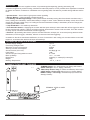
EN50131-1 Grade 2
Environmental Class 4
ISIDE
140
SIRENA AUTOALIMENTATA
MANUALE
HANDBOOK
BACK-UP BATTERY SIREN
ITALIANO
ISIDE è una sirena autoalimentata di potenza 90 dB, è protetta contro le manomissioni antiapertura e antistrappo.
E’ pilotabile con positivo a mancare, oppure positivo a dare, è possibile avere comandi separati di lampeggiatore e altoparlante. E’ dotata di lampeggiatore da 10W, e di un indicatore luminoso a led, con il quale è possibile avere diverse
segnalazioni:
• Stato dell’impianto = segnalazione sonora e/o luminosa dello stato della centrale collegata
• Memoria allarme = segnalazione luminosa di un avvenuto allarme
• batteria scarica e tensione di ricarica = il sistema controlla la bontà della batteria durante la prima accensione, poi
ogni 3 ore, segnalando lo stato di “batteria scarica” in caso di tensione non superiore ai 11Vcc. Oltre al controllo di
batteria, la sirena controlla anche la tensione di ricarica, ogni 10”, segnalandola in caso di avaria.
Le avarie di batteria (carica e tensione) sono segnalate da dei lampeggi veloci dei led.
• Filamento lampada interrotto = viene segnalata con dei lampeggi veloci.
• Stato prima accensione = Alimentatando la sirena con ingressi già in stato di allarme non suonerà, ma ci saranno
4 lampeggi ad indicare il problema. Il lampeggio continuerà finchè gli ingressi non saranno riportati in stato di riposo.
Da questo momento in poi ogni attivazione degli ingressi produrrà un allarme.
• Preallarme = Attivando l’ingresso di allarme la sirena emetterà 10 beep (per 10 secondi) durante i quali se verrà
disattivata, non suonerà, altrimenti scaduti i 10 secondi la sirena inizierà a suonare.
Oltre alle segnalazioni sopracitate, in caso di taglio dei cavi di collegamento, la sirena senza controllo suonerà per 10
minuti, dopodichè si fermerà automaticamente.
SPECIFICHE TECNICHE
Tensione nominale di alimentazione:
Tensioni limiti di funzionamento:
Corrente assorbita alla massima potenza:
Corrente assorbita a riposo:
Pressione sonora (a Vn=12V ):
Potenza luminosa:
Temporizzazione suono e lampeggio senza controllo:
Batteria in tampone:
Dimensioni:
Peso:
Temperatura di esercizio:
www.amcelettronica.com
ISIDE 140
13,8 V
11 ¸ 15 V
800mA
20 mA
90 dB(A) a 3 m
10W
9’ ± 20%
12 V , 1 o 2 Ah
330mm(L) x 220mm(H) x 60mm(P)
700g
- 25 °C ¸ + 55 °C
installation instructions
REGOLAZIONI E COLLEGAMENTI
Morsetti TAMPER : contatto N.C. antiapertura e antistrappo
Morsetti SUPPLY : alimentazione 13,8 V ( nominale )
Morsetto TRIG : ingresso di allarme (solo altoparlante, oppure
lampeggiatore e altoparlante)
Morsetto STATE : ingresso di allarme solo lampeggiatore,
oppure di stato impianto
Morsetto DIRECT : ingresso di collegamento per comando a
“a lancio” (collegare il positivo di lancio)
MORSETTI SERRATI
CONFIGURAZIONE DIP-SWITCH
DIP-SWITCH
DIP 1
DIP 2
DIP 3
CONFIG.
ON
- Funzione a lancio abilitata
OFF
- Funzione lancio disabilitata
ON
- Ingressi con positivo a dare*
OFF
- Ingressi con positivo a mancare
ON
- Comando unico lampada/suono su morsetto TRIG
- Ingresso STATE segnalazione stato impianto acustica** (inserito/disinserito)
OFF
- Comandi separati (anche dip 4 deve essere in off)
ON
- Comando unico lampada/suono su morsetto TRIG
- Ingresso STATE segnalazione luminosa stato impianto** (inserito/disinserito)
- Memoria di allarme (lampada lampeggiante)
DIP 4
DIP 5
DIP 6
DESCRIZIONE FUNZIONE
NOTA: SE IL DIP 3 È IN ON LO STATO IMPIANTO SARÀ SEGNALATO ANCHE ACUSTICAMENTE
OFF
- Comandi separati (anche dip 3 deve essere in off)
ON
Preallarme attivato
OFF
Preallarme disattivo
ON
Led di segnalazione attivato
OFF
Led di segnalazione disattivato
✻ Segnalazione acustica di inserito = 4 bip acuti - segnalazione luminosa = led acceso fisso
✻Segnalazione acustica di disinserito = 1 bip grave - segnalazione luminosa = led rosso 1 lampeggio ogni 2 secondi
INSTALLAZIONE
1. Configurare i dip-switch in funzione della modalità di attivazione prescelta;
2. Se si desidera avere le segnalazioni di stato impianto e memoria di allarme, si ricordi di dare un positivo a centrale inserita al morsetto STATE;
3. Collegare la batteria tampone da 12 V 1 o 2 Ah ai fili rosso e nero con faston;
4. Collegare l’alimentazione esterna da 13,8 V ai morsetti SUPPLY ;
5. Collegare la linea “positivo a mancare/dare” al morsetto TRIG per comandi unici oppure TRIG + STATE per comandi separati;
6. I contatti antiapertura e antistrappo sono collegati in serie e devono essere connessi al relativo circuito della
centrale di allarme attraverso i contatti TAMPER;
9. Chiudere la sirena con il coperchio in plastica.
www.amcelettronica.com
ISIDE 140
installation instructions
ENGLISH
ISIDE is a 90dB power auto supplied sounder, it’s protected agaist tampering (opening and tearing off).
Could be configured as positive missing, otherwise as start with positive, it’s also possible have separated commands
for flasher and buzzer. It features a 10W flasher and a signalling LED, with which is possible having different notifications:
• System Status = Sound and/or Light system status signalling.
• Alarm’s Memory = Light signalling of happened alarm.
• Low Battery and Recharge Voltage = The system checks the battery during the first activation and then every 3
hours, notifing the “low battery” status when battery’s voltage is under 11Vdc. Besides the battery check, the sounder
checks the recharge voltage every 10” notifing an eventual breakdown. Battery’s breakdown (level and charge) are
notified by fast LED’s blinks.
• Lamp Breakdown = It’s notified by fast blinks.
• First Activation Status = Supplying the sounder with the inputs already in alarm state this will not trigger but will notify the problem with 4 blinks. It will go on blinking until the inputs doesn’t returns in the rest state. From this moment
on every input’s activation will make the sounder triggering.
• Prealarm = By activating the alarm’s input the sounder will emits 10 beeps (for 10 seconds) during which if will be
deactivated, it will not trigger, otherwise, after the 10 seconds it will start triggering.
In addition to the above mentioned notifications, in case of connection’s wire cutting, the sounder without control will
trigger for 10 minutes after which it will stops automatically.
TECHNICAL SPECIFICATIONS
Nominal Supply Voltage:
Functioning Voltage Limits:
Maximum Current Consumption:
Stand-by Current Consumption:
Sound Pressure (Vn=12V ):
Light Power:
Sound and Light Timing without control:
Back-up Battery:
Dimensions:
Weight:
Working Temperature:
CONNECTIONS AND TUNINGS
13,8 V
11 ¸ 15 V
800mA
20mA
90 dB(A) @ 3 m
10W
9’ ± 20%
12 V , 1 or 2 Ah
330mm(L) x 220mm(H) x 60mm(P)
700g
- 25 °C ¸ + 55 °C
TAMPER Clamps: N.C. Antiopening and Tearing Off Contact
SUPPLY Clamps: 13,8 V Supply ( Nominal )
TRIG Clamp: Buzzer Only (or Flasher and Buzzer) Alarm Input
STATE Clamp: Flasher Only Alarm Input (or System Status)
DIRECT Clamp: “Launching” Command Input (Connect the
Starting Positive)
TERMINAL STRIP CLOSED
www.amcelettronica.com
ISIDE 140
installation instructions
DIP-SWITCHES CONFIGURATION
DIP-SWITCH
DIP 1
CONFIG.
ON
DIP 2
DIP 3
OFF
- Lunching Function Disabled
ON
- Start with Positive Inputs
OFF
- Positive Missing Inputs
ON
- Light/Sound Unique Command on TRIG Clamp
- STATE Input for Acoustic System Status Notification* (Armed/Disarmed)
OFF
- Separated Commands (DIP 4 MUST BE OFF))
ON
- Light/Sound Unique Command on TRIG Clamp
- STATE Input for Acoustic System Status Notification* (Armed/Disarmed)
- Alarm’s Memory (Flashing Lamp)
DIP 4
DIP 5
DIP 6
FUNCTION’S DESCRIPTION
- Launching Function Enabled
NOTE: IF DIP 3 ON SYSTEM STATUS WILL BE NOTIFIED ALSO BY BUZZER
OFF
- Separated Commands (DIP 3 MUST BE OFF)
ON
Prealarm Activated
OFF
Prealarm Deactivated
ON
Signalling LED Activated
OFF
Signalling LED Deactivated
✻ Armed Acoustic Notification = 4 High Tone Beeps - Visual Notification = Red LED ON
✻ Disarmed Acoustic Notification = 1 Low Tone Beep - Visual Notification = Red LED Blinks Every 2 seconds
INSTALLATION
1. Set up the dip-switches according to the selected activation’s mode ;
2. If System Status Signalling and Alarm Memory are desired, remember to connect STATE Input to a System
Status Positive Output;
3. Connect the 12 V 1 or 2 Ah Back-up battery to the red and black wires with fastons;
4. Connect the 13,8 V external supply to the SUPPLY Clamps;
5. Connect the “positive missing/giving” line to the TRIG clamp for unique commands or TRIG + STATE for separated
commands;
6. Antiopening and antitearing off contacts are connected “in serie” and have to be connected to the relative control
unit’s contacts by the TAMPER Clamps;
9. Close the sounder with the cover.
L’installazione deve essere eseguita a regola d’arte da personale specializzato.
Il produttore declina ogni responsabilità nel caso in cui il prodotto venga manomesso da persone non autorizzate.
Si raccomanda di verificare il corretto funzionamento del sistema d’allarme almeno una volta al mese, tuttavia un sistema
di allarme elettronico affidabile non evita intrusioni, rapine, incendi o altro, ma si limita a diminuire il rischio che tali situazioni si verifichino.
Installation must be carried out following the local installation norms by qualified personnel.
The manufacturer refuses any responsibility when changes or unauthorized repairs are made to the product/system.
It is recommended to test the operation of the alarm product/system at least once a month. Despite frequent testing and
due to, but not limited to, any or all of the following: tampering, electrical or communication disruption or improper use, it
is possible for the product/system to fail to prevent burglary, rubbery, fire or otherwise. A properly installed and maintained
alarm system can only reduce the risk that this happens.
www.amcelettronica.com
ISIDE 140
installation instructions
![[User manual] - KX_series_user_EN](http://vs1.manualzilla.com/store/data/005985322_1-73e2348e6003cbf1e0abe0da04f5dcec-150x150.png)