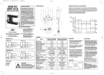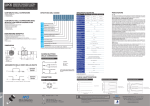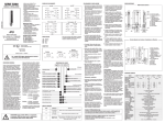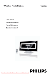
1
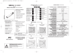
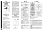
emitter without adjustment
receiver
emitter/receiver pair
Specific applications
Wood industry: way in of wood tables with irregular
profiles
Wood industry: detection of a long board (even in the
presence of vibrations) coming out from a rolling machine
Metal processing: control of sheets coming out from
rolling machines (even in the presence of vibrations)
Control of output material presence
Strada S.Caterina, 235 - 41100 Modena Italy
Tel. +39 059 420411 Fax +39 059 253973
www.microdetectors.com
[email protected]
Detection of object presence on the conveyor belt
Counting of objects being unloaded
S
0
emitter
E
R
SR
D
Two independent outputs
PNP and NPN, both in the
same state.
20
244
199
27
11.5
14
3
Output
state
0
0
emitter with Check function option.
X
dark-pulse receiver (NO, normally open) A
light-pulse receiver(NC, normally closed,
C
not standard)
receiver with NO/NC selection (not standard)
22
12
emitter
1.5
M12x1
Ch.13
M18x1
x
Pg 7
Ω5
• SUPPLIED MATERIAL
Installation Manual
Sensor / Sensors depending by code
N. 1. bracket ST18-C for each element
N. 1. M18 metal fastening ring nut for each element.
Trimmer adjustment accessori ST82
422
20
Axial cable exit
M12 metal plug cable exit
Sensitivity adjustment
Yellow LED
Red LED
Mounting bracket ST18-C
• SPECIFICATIONS
• GENERAL DESCRIPTION
New generation of multiple beam photoelectric
area sensors for detecting the presence or
passage of objects; no wiring synchronism
between emitter and receiver is required.
The new housing, rectangular and extremely
compact, is manufactured through the
injection moulding technique. The use of
fibreglass-strengthened plastic together
with walls of substantial thickness, make
the housing extremely strong and suitable
for use in industrial environments. The
protection degree is IP67. These sensors'
operation is based on the total beam
crossing principle: the emitter photodiodes
are switched on one at a time in sequence
and the light given out by each emitter
must be seen simultaneously by all of the
receiver photodiodes. The height of the area
checked is 90 mm, irrespective of the
number of beams (whether 4 or 10). The
light from the emitter is modulated to
minimize sensitivity of the system to
ambient light. The product features a
nominal sensing range of 2000mm and a
minimum range of 300mm (blind zone); all
models have a 90mm high optical lens, the
10-beam version has a 10mm optical
element spacing, which is 30mm for the 4beam version. The Light-dark response time
is maximum 1ms, the minimum duration of
the dark pulse is 5ms, extendable to 80ms
in the special models with delay off. The
Output
type
7.2
9
23
Materials handling: detection of differently sized or
irregularly shaped objects
Element
5
IP 67 protection degree
emitter with sensitivity
adjustment
A
PG7cable exit, M18
thread available for
fastening with bracket
ST18-A or C.
14.7
10
H
1.1
Ω 4.2
120
ten optical elements, 10mm
element spacing, area
height 90mm
M12 plug, M18
thread available for
fastening with bracket
ST18-A or C.
44
5
04
20
110
four optical elements,
30mm element spacing,
area height 90mm
electrical damages.
Extremely strong housing.
144
R 16.5
Output
connection
Type
90
Complete protection against
B
BX
4
Sensing range up to 2m
Ghiera M18x1
3
area sensor in
rectangular plastic
housing
20x45x120mm
Range
0.3 - 2 m sensing
range
MODEL
emitter has only one green LED indicating
emission which, in the version with the
check function, switches off when the check
mode is active. The receiver has two LEDs,
one yellow and one red. The brightness of
the red LED is inversely proportional to the
level of the signal; the LED switches off
when the signal is sufficient and it does not
indicate excess gain. The yellow LED lit
indicates that the output is ON. The receiver
features two available outputs, PNP and
NPN. The dark-pulse/light-pulse selection
function is available. Emitter with or
without check function are available. The
emitter power can be adjusted by means of
the trimmer.
The main applications are implemented
placing emitter and receiver at opposite
sides of a conveyor belt and orientating
them perpendicularly to the motion
direction. Depending on the different
requirements and on the objects to be
detected, the controlled area can lie
entirely above the belt conveying surface,
or it can be half above and half below the
said surface. In this last case, the BX pair
is positioned at an interruption in the
belt, at the end or at the separation point
between two adjacent belts. The sensor
thickness of only 20mm is particularly
suitable for applications of the latter type.
Type
Nom. Sensing Distance (Sn)
Emission
Controlled Area Height
Operatine Distance
Minimum Detectable Object
Differential Travel
Operating Voltage
Ripple
No-load Supply Current
Load Current
Leakage Current
Voltage Drop
Output Type
Response Time (Light/Dark)
Response Time (Dark/Light)
Time Delay Before Availability
Supply Electrical Protections
Output Electrical Protections
Temperature Range
Interferece to External Light
Protection Degree
LED Indicator (emitter)
LED Indicator (receiver)
Housing Material
Lenses Material
Tightening Torque
Weight (approx.)
(1)
BX04/**-**
Guaranteed resolution everywhere in the detection area
Guaranteed resolution in the central part of the detection area with exclusion of the dark zones
As note (2), but with sensivity adjustment
(4)
NC output models available on request
Dark zones are parts of the detection area close to the emitter and the receiver, their amplitude X is
proportional to the distance D between the emitter and the receiver.
(2)
(3)
BX10/**-**
Medium Resolution Area Sensor
2m
Infrared (880nm) modulated
90mm
2m
φ35(1) / φ25(2) / φ15(3) mm
φ15(1) / φ7.5(2) / φ5(3) mm
<10%
10 – 26 Vdc
10%
50 mA (emitter) – 25 mA (receiver)
100 mA
< 10 µA (at VDC max.)
2 V at 100 mA
NPN + PNP – NO Standard(4)
500 µs
5 ms
100 ms
Polarity Reversal, Transient
Short Circuit (autoreset)
-5 /+ 55 °C (without freeze)
1000 lux (incandescent lamp) – 1500 lux (sunlight)
IP67 (EN60529)
Green (power and emission)
Red (alarm) – Yellow (output state)
Valox
PC
25 Nm
260…300 (plug) - 800g (cable)
BX04: X=0.17D
BX10: X=0.06D
Connections
1) Make sure that the operating voltage is correctly
stabilized with a maximum ripple lower than that
given in the catalogue.
2) In the event that the noise induced by the power
lines is greater than that foreseen by the EMC
regulation (interference immunity), detach the
sensor cables from the power and high voltage
lines and insert the cable in an earthed metal
cable trough. Furthermore, it is advisable to
connect the sensor directly to the supply source
and not downstream other devices.
3) To extend the supply and output cables use a
cable featuring wires with a minimum crosssection of 1mm2. The extension limit in length is
100m (with respect to a minimum voltage and
load current of 100mA).
4) The sensor state will be active only 100ms after
voltage has been supplied. During this time, the
outputs will be OFF.
Mounting
1) The use of the brackets ST18-C is advised for a
perfect mounting and alignment.
2) Do not allow dust, water and condensation to
deposit on the element optics.
3) Avoid exposing the optics to chemical reactive
products
4) Do not allow strong light or sunlight to fall directly
onto the receiver optical element.
5) For cleaning, use a wet cloth and then dry all parts.
Alignment / Adjustment
1) Check that the distance between the emitter and
the receiver falls within the specification range of
the model used. Arrange the brackets so that the
displacement between the axes of the two parts
(emitter and receiver) lies within ±1,5°.
2) Position the optical lenses facing one other,
aligning them as much as possible with the axis
joining the two parts.
3) Check the wiring and supply power to the system.
The green LED on the emitter switches on (check
also that, in the emitters, the sensitivity
adjustment trimmer is rotated in a clockwise
direction to the final position).
4) Rotate the emitter checking the receiver's red
LED and searching the minimum brightness
position or switching-off; secure it provisionally
in this position.
5) Rotate the receiver checking its red LED and
searching the minimum brightness position or
switching-off; secure it provisionally in this
position.
6) Repeat points 4 and 5 until the red LED on the
receiver switches off.
7) If it is not possible to switch off the receiver's red
LED, check the relative height, parallelism and
distance between the two elements, and try to
improve the conditions referring to the minimum
brightness of the LED. Points 8 to 10 are used to
obtain the highest possible signal margin, which is
useful in the case of demanding working conditions.
8) Rotate the trimmer on the emitter in an
anticlockwise direction, until the receiver's red
LED switches on with a medium-low brightness.
9) Orientate the emitter and the receiver as
described in points 4 and 5, so as to find the
minimum brightness area or switching-off.
10) Repeat points 8 and 9 so as to improve the beam
aiming, then bring the trimmer back to its
(threshold) position.
11) To detect small object , rotate the trimmer in a
clockwise direction a few degrees beyond the
point at which the red LED switches off.
12) Check the detection of the required diameters and
secure the system.
N.B. The trimmer adjustment is indispensable for
obtaining a maximum resolution, above all in the
event that emitter and receiver are positioned at a
distance lower than the nominal one, or in the
detection of semitransparent objects. Very small
diameters cannot be detected regularly in
proximity of the optical elements, but are
detected in the central zone, this being the
maximum resolution area. The dark zone within
which such diameters cannot be detected, can be
obtained from the figure below and from the
previously described formulas.
The dimension of the blind zone is found using the
following formula:
x = 0,06 * d 10-optics sensor
x = 0,17 * d 4-optics sensor
• WIRING DIAGRAMS
EMITTER CONNECTIONS
RECEIVER CONNECTIONS
BN
1
+
BN
1
+
BU
3
-
BU
3
BK
4
BK
4
pnp out
WH
2
WH
2
npn out
check check +
Model BX**S/XO -**
WIRING
1/Bn :
2/Wh :
3/Blu :
4/Blk :
Model BX**R/*D-****
COLORS
Brown
White
Blue
Black
• DIAGNOSTIC
LED
STATUS
CONDITION
GREEN emitter
SUPPLY
ON
Supply
YELLOW receiver ON
OUTPUT
OFF
RED receiver
ALIGNMENT
ON state output
OFF state output
BRIGHT ON
LESS BRIGHT ON
OFF
No alignment
Partial alignment or low received signal
Good alignment and enough received signal
• CONNECTORS
Check (-)
Supply (-)
4
3
1
2
Supply (+)
Check (+)
• EMITTER
(OUT PNP)
Supply (+)
Supply (-)
4
3
1
2
(OUT NPN)
• RECEIVER
WARNING
These products are
NOT safety sensors
and are NOT suitable
for use in personal
safety application
CAT8BBX0214702
Staffa dis. 2628
and check input on request.
Controlled area hight up to 90 mm
• INSTALLATION AND
ADJUSTMENT PROCEDURES
BX 04 S / 0 0 - H B
Series
Emitter with power adjustment
• MECHANICAL DRAWINGS
20
Installation manual
• CODE DESCRIPTION
~18.5
SERIE BX
MINIATURE DC AREA SENSOR
WITH 4 OR 10 OPTICAL ELEMENTS
IN A RECTANGULAR HOUSING
Elemento
Tipo
d’uscita
danneggiamenti di tipo elettrico
emettitore con regolatore di
sensibilità
S
0
Contenitore di grande robustezza
emettitore senza regolazione
E
R
SR
coppia emettitore/ricevitore
Macchine per legno : Rilevazione di una tavola
(anche con vibrazioni) in uscita da rulliere
www.microdetectors.com
[email protected]
Controllo presenza materiale in uscita
Rilevazione di presenza oggetti su nastro trasportatore
Conteggio di particolari in caduta.
20
244
199
14.7
Due uscite indipendenti
27
11.5
C
emettitore con possibilità di Check
3
5
12
ricevitore impulso luce
(NC, normalmente chiuso, non standard)
ricevitore con selezione NA/NC (non standard)
23
ricevitore impulso buio
(NA, normalmente aperto)
0
0
X
A
emettitore
14
1.5
M12x1
Ch.13
M18x1
x
Pg 7
Ω5
• CONTENUTO DELLA CONFEZIONE
Manuale di installazione
Sensore / Sensori dipendentemente dal codice
N. 1. staffa ST18-C per ogni elemento
N. 1. ghiera metallicha M18 per ogni elemento
Accessorio di regolazione trimmer ST82
422
20
Uscita cavo assiale
Uscita connettore M12 metallico
Regolazione sensibilità
LED giallo
LED rosso
Staffa di fissaggio ST18-C
• SPECIFICHE
• DESCRIZIONE GENERALE
Nuova generazione di sensori fotoelettrici di
area a raggi multipli, per intercettazione di
presenza o passaggio di oggetti che non
necessita di un sincronismo cablato fra
proiettore e ricevitore. Il nuovo contenitore,
di forma parallelepipeda e di dimensioni
estremamente compatte, è ottenuto per
stampaggio a iniezione. L’uso di plastica
caricata con fibre di vetro abbinato a pareti
di grande spessore, lo rendono
estremamente robusto e adatto all’impiego
in ambienti industriali. La protezione è
IP67. Il principio di funzionamento è quello
dell’intreccio totale: i LED dell'emettitore
sono accesi uno alla volta in sequenza e la
luce emessa da ciascun emettitore deve
essere vista contemporaneamente da tutti i
fotododi del ricevitore. L’altezza dell’area
controllata è di 90mm, indipendentemente
dal numero dei raggi (siano 4 o 10).
L’emissione è modulata per minimizzare la
sensibilità del sistema alla luce ambiente. Il
prodotto presenta portata nominale pari a
2000 mm , portata minima (zona cieca) pari
a 300mm , altezza della finestra ottica
90mm per tutti i modelli, passo ottiche
10mm per la versione a 10 raggi, 30mm per
la versione a 4 raggi. Il tempo di risposta
luce/buio è massimo 1ms, la durata minima
dell’impulso buio è 5ms, allungabile a 80ms
nei modelli speciali con delay off.
L’emettitore ha un solo LED verde indicante
7.2
nello
D PNP ed NPN, ambedue
stesso stato.
Stato
uscita
Lavorazione metalli: controllo di lamiere sottili in
uscita da rulli anche con vibrazioni
Strada S.Caterina, 235 - 41100 Modena Italy
Tel. +39 059 420411 Fax +39 059 253973
emettitore
9
Applicazioni tipiche
Macchine per legno : Ingresso di tavole in legno con
profilo variabile
A
Passacavo PG7, filetto
M18 disponibile per
fissaggio con staffa
ST18-A o C
22
ricevitore
H
120
10
1.1
Ω 4.2
5
dieci ottiche passo 10 mm,
altezza area 90 mm
connettore M12,
filetto M18 disponibile
per fissaggio con
staffa ST18-A o C
44
110
04
20
90
quattro ottiche passo 30
mm, altezza area 90 mm
Totalmente protetti contro
Movimentazione : controllo presenza oggetti in posizioni
non ripetibili e/o di forme variabili o irregolari
144
R 16.5
Attacco
d’uscita
Tipo
Distanza di lavoro nominale 2 m.
Grado di protezione IP67
4
Controllo di aree di altezza 90mm.
B
BX
3
sensore di area in
contenitore plastico
rettangolare
20x45x120mm
Ghiera M18x1
Portata
portata 0.3 - 2 m
MODELLO
l’emissione, che nella versione con check si
spegne quando il check è attivo.
Il ricevitore presenta due LED uno giallo e
uno rosso. Il led rosso si illumina in modo
proporzionale all’inverso del livello del
segnale ed è spento quando il segnale è
sufficiente. Il LED non indica l’eccesso di
guadagno. Il LED giallo acceso indica che
l’uscita è ON. Il ricevitore rende disponibili
due uscite PNP ed NPN. E’ disponibile la
funzione impulso-buio impulso-luce
selezionabile. Disponibile emettitore con o
senza funzione di check. E’ disponibile
nell’emettitore la possibilità di regolare la
potenza emessa mediante trimmer.
Le applicazioni principali sono realizzate,
ponendo proiettore e ricevitore ai lati
opposti di un nastro trasportatore con
orientamento perpendicolare al senso di
moto. A seconda delle necessità e degli
oggetti da intercettare, l’area sensibile può
essere tutta al di sopra del piano di
trasporto del nastro, oppure può essere per
metà al di sopra e per metà al di sotto del
piano di trasporto, in questo ultimo caso la
coppia di BX sarà posizionata in
corrispondenza di una interruzione del
nastro,alla fine dello stesso, o nel punto di
separazione tra due nastri affiancati. Lo
spessore di soli 20mm del sensore favorisce
le applicazioni di questo ultimo tipo.
Tipo
Distanza di lavoro nominale
Emissione
Altezza area sensibile
Distanza di lavoro
Oggetto minimo rilevabile
Corsa differenziale
Tensione di alimentazione
Ondulazione residua
Corrente assorbita
Corrente di uscita
Corrente di perdita
Caduta tensione in uscita
Tipo uscita
Tempo di risposta ( Luce/buio)
Tempo di risposta (buio/luce)
Ritardo alla disponibilità
Protezioni elettriche alimentazione
Protezioni elettriche uscita
Limiti di temperatura
Interferenza alla luce esterna
Grado di protezione
Indicatori LED ( emettitore)
Indicatori LED ( ricevitore)
Materiale contenitore
Materiale ottiche
Coppia serraggio
Peso (approssimativo)
(1)
BX04/**-**
Risoluzione garantita in qualsiasi punto dell’area
Risoluzione garantita nella parte centrale dell’area escludendo le zone buie
Come nota (2), ma utilizzando la regolazione di sensibilità
(4)
Modelli con uscita NC disponibili a richiesta
Le zone buie corrispondono a parti dell’area adiacenti agli elementi proiettore e ricevitore, hanno una
ampiezza X proporzionale alla distanza D tra proiettore e ricevitore.
(2)
(3)
BX10/**-**
Sensore di area a media risoluzione
2m
Infrarosso (880nm) modulato
90mm
2m
φ35(1) / φ25(2) / φ15(3) mm
φ15(1) / φ7.5(2) / φ5(3) mm
<10%
10 – 26 Vdc
10%
50 mA (emettitore) – 25 mA (ricevitore)
100 mA
< 10 µA (at VDC max.)
2 V at 100 mA
NPN + PNP – NO Standard(4)
500 µs
5 ms
100 ms
Inversione di polarità , sovratensioni impulsive
Cortocircuito (autoripristinante)
-5 /+ 55 °C (senza condensa)
1000 lux (lampada ad incandescenza) – 1500 lux (Luce solare)
IP67 (EN60529)
Verde ( emissione abilitata)
Rosso (margine di segnale) – Giallo (stato uscita)
Valox
PC
25 Nm
260…300 (connettore) 800g (cavo)
BX04: X=0.17D
BX10: X=0.06D
Connessioni
1) Assicurarsi che la tensione di alimentazione sia
correttamente stabilizzata con una ondulazione
residua massima inferiore ai dati di catalogo.
2) Nel caso che il rumore indotto dalle linee di
potenza risulti superiore a quello previsto dalla
normativa CE (immunità ai disturbi), separare i
cavi del sensore dalle linee di potenza e di alta
tensione e inserire il cavo in una canalina
metallica connessa a terra. E’ consigliabile inoltre,
collegare il sensore direttamente alla sorgente di
alimentazione e non a valle di altri dispositivi.
3) Per estendere i cavi di alimentazione e uscita
utilizzare un cavo avente conduttori di sezione
minima di 1mm2. Il limite dell’estensione in
lunghezza è 100m (riferiti a tensione minima e
corrente al carico di 100mA).
4) Lo stato del sensore diventa valido solo dopo
100ms dalla fornitura di alimentazione. In questo
periodo le uscite saranno OFF.
Montaggio
1) Si consiglia l’uso della staffe ST18-C per un
perfetto montaggio ed allineamento.
2) Evitare il deposito di materiali come polvere,
acqua, condensa, sull’ottica degli elementi.
3) Evitare l’esposizione dell’ottica a prodotti chimici
aggressivi.
4) Evitare che una luce forte o la luce solare
incidano direttamente sull’ottica del ricevitore.
5) Per la pulizia usare un panno umido e asciugare.
Allineamento / Regolazione
1) Verificare che la distanza tra emettitore e ricevitore
sia compresa nei limiti di specifica del modello
utilizzato. Predisporre lo staffaggio in modo che il
disassamento tra gli assi dei due elementi
(emettitore e ricevitore) risulti compreso tra ±1,5°.
2) Posizionare le finestre delle ottiche una affacciata
all’altra il più possibile corrispondenti all’asse di
congiunzione dei due elementi.
3) Verificare il cablaggio ed alimentare il sistema. Il
LED verde sull’emettitore si accende (verificare
inoltre che negli emettitori il trimmer di
regolazione della sensibilità sia ruotato
nell’estrema posizione in senso orario).
4) Ruotare l’emettitore osservando il LED rosso del
ricevitore ricercando la posizione di minima
luminosità o spegnimento e fissarlo
provvisoriamente in queste condizioni.
5) Ruotare il ricevitore osservando il LED rosso dello
stesso ricercando la posizione di minima
luminosità o spegnimento e fissarlo
provvisoriamente in queste condizioni.
6) Ripetere i punti 4 e 5 fino allo spegnimento del
LED rosso sul ricevitore
7) Nel caso non sia possibile ottenere lo
spegnimento del LED rosso del ricevitore verificare
altezza relativa, parallelismo, distanza dei due
elementi e cercare di migliorare le condizioni
facendo riferimento alla minima luminosità dello
stesso.I punti da 8 a 10 servono per ricavare il
margine di segnale più alto possibile, utile in
condizioni gravose di lavoro.
8) Ruotare il trimmer sull’emettitore in senso
antiorario fino ad ottenere l’accensione del LED
rosso del ricevitore ad una luminosità medio-bassa.
9) Orientare l’emettitore ed il ricevitore come ai
punti 4 e 5 in modo da ricercare la zona di
minima luminosità o spegnimento.
10) Ripetere i punti 8 e 9 in modo da migliorare
l’orientamento poi riportare al massimo il trimmer.
11)Per rilevare piccoli oggetti ruotare il trimmer in
senso orario di alcuni gradi oltre il punto per cui
si ottiene lo spegnimento del Led rosso .
12)Verificare l’ottenimento della rilevazione degli
oggetti desiderati e fissare il sistema.
N.B. La regolazione del trimmer è indispensabile
qualora si desideri ottenere la massima risoluzione,
soprattutto nei casi in cui emettitore e ricevitore
siano posizionati a distanze inferiori a quella
nominale o nella rilevazione di oggetti semitrasparenti.
Diametri molto piccoli non possono essere rilevati
con continuità in prossimità delle ottiche , ma
vengono rilevati nella zona centrale , essendo
questa la zona di massima risoluzione . La zona buia
entro la quale tali diametri non possono essere
rilevati può essere ricavata dalla figura sottostante e
dalle formule precedentemente presentate.
La dimensione della zona cieca X viene fornita dalla
seguente formula:
x = 0,06 * d sensore a 10 ottiche
x = 0,17 * d sensore a 4 ottiche
• CONNESSIONI
EMETTITORE CONNESSIONI
RICEVITORE CONNESSIONI
BN
1
+
BN
1
BU
3
-
BU
3
BK
4
BK
4
pnp uscita
WH
2
WH
2
npn uscita
check check +
Modello BX**S/XO-**
CODICE
1/Bn :
2/Wh :
3/Blu :
4/Blk :
+
Modello BX**R/*D-****
COLORI
Brown/Marrone
White/Bianco
Blue/Blu
Black/Nero
• DIAGNOSTICA
LED
STATO
CONDIZIONE
VERDE emettitore ACCESO
SUPPLY
Alimentazione presente e stabile
GIALLO ricevitore ACCESO
OUTPUT
SPENTO
Uscita in stato ON
Uscita in stato OFF
ROSSO ricevitore
ALLINEAMENTO
ACCESO intenso
ACCESO tenue
SPENTO
Nessun allineamento
Allineamento parziale o scarso segnale ricevuto
Allineamento corretto e segnale sufficiente
• CONNETTORI
Check (-)
Alimentazione (-)
4
3
1
2
Alimentazione (+)
Check (+)
• EMETTITORE
(USCITA PNP)
Alimentazione (+)
Alimentazione (-)
4
3
1
2
(USCITA NPN)
• RICEVITORE
ATTENZIONE
Questo prodotto non è un
sensore di sicurezza
e non può essere
utilizzato come
protezione di accesso a
zone pericolose.
CAT8BBX0214702
Staffa dis. 2628
portata a mezzo trimmer, ed
ingresso di check su richiesta.
• PROCEDURE DI INSTALLAZIONE
E REGOLAZIONE
BX 04 S / 0 0 - H B
Serie
Emettitore con regolazione di
• DISEGNI MECCANICI
20
Manuale di installazione
• DESCRIZIONE DEL CODICE
~18.5
SERIE BX
SENSORE DI AREA A 4 O 10
OTTICHE MINIATURIZZATO DC IN
CONTENITORE PARALLELEPIPEDO