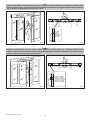
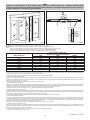
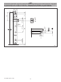
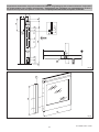
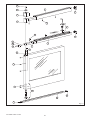
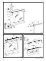
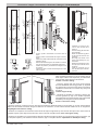
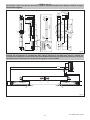
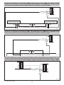
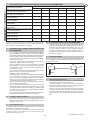
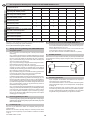
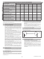
1
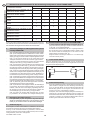
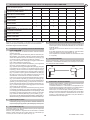
AST-ASME-ASMI
IP1628 - rev. 2008-06-03
I
GB
F
D
E
P
DITEC S.p.A.
Via Mons. Banfi, 3 - 21042 Caronno Pertusella (VA) - ITALY
Tel. +39 02 963911 - Fax +39 02 9650314
www.ditec.it - [email protected]
Manuale di installazione
per dispositivi a
sfondamento.
Installation manual for
break-out devices.
Manuel d’installation
pour dispositives de
défocement.
Wartungshandbuch für
Durchbohrungsvorrichtung.
Manual para la instalaciòn
para dispositivos de
desfonde.
Manual de instalação para
dispositivos de abertura.
AST
Sistema di sfondamento ante mobili e fisse / Panic system for mobile and fixed wings / Système d’enfoncement
vantaux mobiles et fixes / Break-Out-System für Fahrflügel und Seitenteile / Sistema de desfonde hojas móviles
y fijas / Sistema de abertura de folhas móveis e fixas
min. 2000
10.5
Fotocellula
Photocell
Photocelle
Lichtschranke
Fotocélulas
Fotocélulas
Fig. 1
Fig. 2
ASME
Sistema di sfondamento sole ante mobili / Panic system for mobile wings only / Système d’enfoncement
vantaux mobiles seulement / Break-Out-System nur für Fahrflügel / Sistema de desfonde, sólo hojas móviles /
Sistema de abertura somente para folhas móveis
min. 2000
8÷10
Fig. 3
AST-ASME-ASMI - IP1628
Fotocellula + KASME
Photocell + KASME
Photocelle + KASME
Lichtschranke + KASME
Fotocélulas + KASME
Fotocélulas + KASME
Fig. 4
2
ASMI
Sistema di sfondamento sole ante mobili / Panic system for mobile wings only / Système d’enfoncement
vantaux mobiles seulement / Break-Out-System nur für Fahrflügel / Sistema de desfonde sólo hojas móviles /
Sistema de abertura somente para folhas móveis
min. 2000
10.5
Fotocellula
Photocell
Photocelle
Lichtschranke
Fotocélulas
Fotocélulas
Fig. 5
Fig. 6
Attenzione: il sistema ASMI è sfondabile solo con ante completamente chiuse.
Warning: the ASMI system can be broken through only when wings are fully closed.
Attention: le système ASMI ne peut être enfoncé que si les vantaux sont complètement fermés.
Achtung: das ASMI System kann nur aufgeschwenkt werden, wenn die Türflügel vollständig geschlossen sind.
Atenciòn: el Sistema ASMI es desfondable únicamente si las hojas están completamente cerradas.
Atenção: o sistema ASMI pode ser aberto somente se as folhas estiverem completamente fechadas.
Larghezza anta
Wing width (mm)
min. 650
700
800
900
1000
1100
1200 (*)
1300 (*)
1400 (*)
Peso massimo singola anta
Single wing maximum weight (Kg)
TEN
100
100
100
80
70
60
/
/
/
REX
100
100
100
80
70
60
/
/
/
BISO-V
120
120
120
110
110
100
100
90
80
Attenzione: i sistemi di sfondamento AST, ASME e ASMI sono omologati TÜV in abbinamento ad automazioni DITEC modelli BIS-O, BIS-V e TEN, e presso il Ministero
dell’Interno della Repubblica Italiana in abbinamento ad automazione REX. Le ante utilizzate sono da intendersi costruite con profili DITEC serie PAM35-PAM35F.
L’altezza massima delle ante mobili sfondabili (HM) non deve superare 2400 mm.
Quando il peso dell’anta fissa è superiore a 100 kg, aggiungere una terza cerniera (vedere KCER2).
(*) Aggiungere il terzo carrello sull’anta.
Attention: AST, ASME and ASMI panic devices are TUV approved coupled with DITEC automation models BIS-O, BIS-V and TEN, and approved coupled with REX
automation by the Minister of Interior of the Italian Republic. The wings utilised are to be constructed with DITEC PAM35-PAM35Fprofiles. The break-out mobile wings
(HM) should not exceed 2400 mm in height.
Add a third hinge (see KCER2) when the weight of the fixed wing exceeds 100 kg.
(*) Add a third carriage on the wing.
Attention: les systèmes de défoncement AST, ASME et ASMI sont homologués TÜV en couplage avec les automations DITEC modèles BIS-O, BIS-V et TEN, et auprès
du Ministère de l’intérieur de la République Italienne en couplage avec l’automation REX. Les portes utilisées sont construites avec des profils DITEC série PAM35PAM35F. La hauteur maximum des portes mobiles qui peuvent être défoncées (HM) ne doit pas dépasser 2400 mm.
Quand le poids de la porte fixe est supérieur à 100 kg, ajouter une troisième charnière (voir KCER2).
(*) Ajouter le troisième chariot sur la porte.
Achtung: die Break-Out-Systeme AST, ASME und ASMI sind in Verbindung mit den DITEC-Automationsmodellen BIS-O, BIS-V und TEN, und beim Innenministerium der
italienischen Republik in Verbindung mit der REX-Automation, TÜV geprüft. Die verwendeten Flügel werden mit DITEC-Profilen der Serie PAM35-PAM35F hergestellt.
Die Höhe der Fahrflügel mit Break-Out-System (HM) darf 2400 mm nicht überschreiten.
Liegt das Gewicht des festen Flügels über 100 kg, muss ein drittes Scharnier hinzugefügt werden (siehe KCER2).
(*) Den dritten Fahrflügel hinzufügen.
Atención: los sistemas antipánico de hojas abatibles por simple empuje manual AST, ASME y ASMI poseen la homologación TÜV si están instalados en combinación
con automatizaciones DITEC de los modelos BIS-O, BIS-V y TEN, y poseen también la homologación Ministerio del Interior de la República Italiana en combinación
con la automatización REX. Se entiende que las hojas utilizadas están construidas con perfiles DITEC serie PAM35-PAM35F. La altura máxima de las hojas móviles
abatibles por simple empuje manual (HM) no debe ser superior a 2400 mm.
Si el peso de la hoja fija supera los 100 kg, será necesario añadir una tercera bisagra (ver KCER2).
(*) Añadir una tercera corredera a la hoja.
Atenção: os sistemas antipânico AST, ASME e ASMI são homologados TÜV adequados a automações DITEC modelos BIS-O, BIS-V e TEN, e no Ministério do Interior
da República Italiana adequado a automação REX. As portas utilizadas devem ser construídas com perfis DITEC série PAM35-PAM35F. A altura máxima das portas
móveis de correr (HM) não deve superar os 2400 mm.
Quando o peso da porta fixa for superior a 100 kg, adicionar uma terceira dobradiça (ver KCER2).
(*) Adicionar o terceiro carrinho à porta de correr
3
AST-ASME-ASMI - IP1628
ASME
Preparazione anta mobile con profili commerciali / Mobile wing setting up with commercial frames / Préparation
du vantail mobile avec profilés commerciaux / Vorbereitung des Fahrflügel mit handelsüblichen Profilen /
Preparación hoja móvil con perfiles comerciales / Preparação da folha móvel com perfis comerciais
Ø13
100
20
130
75
20
50
OPEN
min 40
HM
OPEN
100
8÷10
12
45
20
37
AST-ASME-ASMI - IP1628
Fig. 7
4
ASMI
Preparazione anta mobile con profili commerciali / Mobile wing setting up with commercial frames / Préparation
du vantail mobile avec profilés commerciaux / Vorbereitung des Fahrflügel mit handelsüblichen Profilen /
Preparación hoja móvil con perfiles comerciales / Preparação da folha móvel com perfis comerciais
20
Ø13
130
20
50
100
10.5
HM
100
OPEN
12
Y
OPEN
45 20
32
Fig. 8
HM
Y
LM
Fig. 9
5
AST-ASME-ASMI - IP1628
21
1
11
12
10
5
20
7
+
-
19
13
17
2
9
3
18
8
4
31
16
6
14
15
14
AST-ASME-ASMI - IP1628
Fig. 10
6
SP
4
20
30
71
~20
100
24
~200
300
100
40
20
6MA
3
8
LM
17
45
9
25
30
SP
18
6
4
Fig. 11
Fig. 12
2
21
11
LM-1
1
LM-5
10
12
1
5
20
8
2
13
4
LM
LM
fig. 13
fig. 14
7
AST-ASME-ASMI - IP1628
Kit cerniere / Hinges / Kit charnières / Scharniere / Bisagras / Kit de dobradiças
179
23
Ø9.3
Ø9.3
Ø9.3
Ø9.3
23
Ø9.3
A
Ø9.3
23
23
Ø9.3
Ø9.3
23
Ø9.3
M6
118
M6
130
163
A
Ø9.3
LEFT MOUNTING
A
Ø9.3
- Forare i profili e assemblare le cerniere come da
figura.
- Drill the profiles and assemble the hinges as show in
figure.
- Percer les profilés et assembler les charnières comme
indiqué en figure.
- Nehmen Sie die Bohrungen in den Profilen vor und setzen Sie die Scharniere wie abgebildet zusammen.
- Taladrar los perfiles y ensamblar las bisagras como
en la figura.
- Perfurar os perfis e montar as dobradiças como indicado na figura.
RIGHT MOUNTING
- Utilizzare gli inserti [A] nel
caso di ante apribili verso
l’esterno.
- Use the insert [A] for doors that
open externally.
- Utiliser les elements [A] dans
le cas de portes ouvrant vers
l’exterieur.
- Bei Flugel zum Öffnen nach
außen die Befestigung [A]
verwenden.
- Utilizar los insertos [A] en caso
de hojas que se abran hacia
el externo.
- Utilize as inserções [A] no
caso de folhas que se abrem
para fora.
- Inserire le boccole con la freccia rivolta verso l’anta
fissa sfondabile (posizione 0). Per avvicinare l’anta al
telaio agire sulla boccola superiore; per allontanare
l’anta al telaio agire sulla boccola inferiore.
Portata: 2 cerniere 100 kg.
- Insert the bushes with the arrow turned towards
the fixed breakable down wing (position 0). Operate
the upper bush to move the wing closer to the frame;
operate the lower bush to move the wing away from
the frame.
Load: 2 hinges 100 kg.
1 mm
0
0
1 mm - Introduire les douilles en orientant la fléche vers
l’ouvrant (position 0). Agir sur la douille superieure
pour approcher l’ouvrant du dormant; Agir sur la douille
inferieure pour eloigner l’ouvrant du dormant.
Portée: 2 charniéres 100 kg.
- Buchsen einsetzen, wobei der Pfeil zu dem ausschwenkbaren Seitenteil zeigen muss (Position 0). An der oberen Buchse
stellen um den Abstand zwischen Flügel und Rahmen zu verkleinern, an der unteren Buchse stellen um ihn zu vergrößern.
Tragfähigkeit: 2 Scharniere 100 kg.
- Introducir los casquillos con la flecha en direcciòn de la hoja mòvil (posiciòn 0). Para acercar la hoja el marco actuar sobra el
casquillo superior; para alejar la hoja del marco actuar sobra el casquillo inferior. Peso: 2 bisagras 100 kg.
- Introduza os casquilhos com a seta virada na direcção da folha fixa a abrir (posição 0). Para aproximar a folha a estrutura, agir
no casquilho superior; para afastar a folha da estrutura, agir no casquilho inferior. Capacidade: 2 dobradiças 100 kg.
AST-ASME-ASMI - IP1628
8
KSERS1-2-3-4-5
Kit serratura a spillo / Pin lock kit / Kit serrure à broche / Bausatz Stangenschloß / Equipo cerradura de aguja /
Kit fechadura a agulha
LM
10.5
= =
112
HM-251
15
77
Ø3
1x45°
Ø18
Ø8
15
33
70
213
147.5
Ø3
200
16
119
max 7.5
3
32.5
34
M6
HM-251
1x1.5
7
45
Ø6.5
fig. 15
Schema dei collegamenti su sfondamento AST / Wiring diagram for the AST panic device / Schéma des
connexions sur dispositif d’enfoncement AST / Anschlußschema für AST-System / Esquema de las conexiones
del dispositivo de desfonde AST / Esquema das ligações na abertura AST
1
0
Brown
Black
Blue
Brown
Blue
ASM
ASM
OPEN
AST
Black
Brown
Blue
Magnetic switch
CONTROL
PANEL
9
OPEN
TX
RX
SICUR2
Magnetic switch
Black
Brown
Blue
AST
SICUR2
fig. 16
9
AST-ASME-ASMI - IP1628
Schema dei collegamenti su sfondamento ASME / Wiring diagram for the ASME panic device / Schéma
des connexions sur dispositif d’enfoncement ASME / Anschlußschema für ASME-System / Esquema de las
conexiones del dispositivo de desfonde ASME / Esquema das ligações na abertura ASME
1
0
Brown
Black
Blue
Brown
Blue
ASM
KASME
Black
OPEN
ASM
OPEN
TX
9
CONTROL
PANEL
STOP
KASME
RX
Grey
fig. 17
Schema dei collegamenti su sfondamento ASMI / Wiring diagram for the ASMI panic device / Schéma des
connexions sur dispositif d’enfoncement ASMI / Anschlußschema für ASMI-System / Esquema de las
conexiones del dispositivo de desfonde ASMI / Esquema das ligações na abertura ASMI
Brown
Black
Blue
Brown
Blue
ASM
Black
OPEN
9
1
0
CONTROL
PANEL
STOP
ASM
OPEN
TX
RX
Grey
fig. 18
TX
Brown
Blue
9
1
0
CONTROL
PANEL
STOP
9
Brown
Black
Blue
COMH-K
Schema dei collegamenti con selettore di funzioni COMH-K / Wiring diagram with COMH-K function selector / Schéma des
connexions avec sélecteur de fonctions COMH-K / Anschlußschema mit Funktionswählschalter COMH-K / Esquema
de las conexiones con selector de funciones COMH-K / Esquema das ligações com selector de funções COMH-K
RX
fig. 19
AST-ASME-ASMI - IP1628
10
1. Kit necessari per costruzione serramenti con dispositivi AST-ASME-ASMI
Profili commerciali
PAM35-PAM35F
APPLICAZIONE
[*] Kit serratura opzionale
AST Sfondamento di una anta mobile e
una anta fissa con profili PAM35
AST Sfondamento di due ante mobili e due
ante fisse con profili PAM35
ASME Sfondamento di una anta mobile
con profili PAM35
ASME Sfondamento di due ante mobili
con profili PAM35
ASMI Sfondamento di una anta mobile con
profili PAM35
ASMI Sfondamento di due ante mobili con
profili PAM35
ASME Sfondamento di una anta mobile
con profili commerciali
ASME Sfondamento di due ante mobili con
profili commerciali
ASMI Sfondamento di una anta mobile con
profili commerciali
ASMI Sfondamento di due ante mobili con
profili commerciali
KASM1
KASM2
1
-
-
1
1
1
I
KASME
KSERS*
1
-
1
-
2
-
2
-
1
-
1
1
1
1
2
-
1
2
1
-
1
-
-
1
1
1
2
-
-
2
1
-
-
-
1
1
1
1
-
-
1
2
1
-
-
-
-
1
1
1
-
-
-
2
5.
Attenzione: nel caso di verniciatura, i profili devono essere chiusi per
evitare che lo spessore della vernice provochi un cattivo funzionamento.
Non verniciare la guida a pavimento in alluminio.
Collegamenti elettrici sistema AST-ASME-ASMI
- Forare il montante verticale del serramento fisso sul lato del vano
passaggio e montare la fotocellula SICUR2 come indicato in fig. 2-4-6.
- Effettuare i collegamenti elettrici come indicato in fig. 16-17-18.
Se viene utilizzato il selettore di funzioni COMH-K, collegare il
cavo marrone del ricevitore al morsetto 9 del selettore (fig. 19).
- Eventuali altri dispositivi devono essere collegati in serie al collegamento 1-9 (STOP).
2. Preparazione anta e montaggio sistema sfondamento anta
mobile ASME-ASMI
- (Fig. 11) Predisporre un rinforzo in ferro nel traverso superiore dell’anta.
- (Fig. 11) Forare l’anta 30x30 mm e 6MA. In base ai profili utilizzati,
se necessario, inserire all’interno del montante verticale due spessori
SP per mantenere verticali e paralleli al montante i perni [4] e [6].
- (Fig. 11) Montare il perno inferiore [6] nel foro inferiore dell’anta
e fissarlo con le viti [16].
- (Fig. 13-15) In base al senso di sfondamento e alla lunghezza
LM dell’anta, tagliare a misura i profili [1] e [2].
- (Fig. 12) Passare il perno [4] nel foro del piatto [3] e bloccare
l’accoppiamento con la spina [17] inserita fino al dritto del piatto
[3]; posizionare in sede la spina [8] e montare la testata [9] con
la vite [18] sul piatto [3].
- (Fig. 13) Infilare il perno [4] così assemblato nel profilo [2] e fissare
il tutto all’anta con le viti [31] e [19] in dotazione.
Attenzione al senso di sfondamento.
Prevedere almeno un ulteriore punto di fissaggio del profilo [2] all’anta.
- (Fig. 13) Assemblare lo scrocco [7] e passarlo nel profilo [2];
(Fig. 10) la forza di sfondamento dell’anta si regola spostando
lo scrocco [7] lungo il profilo [2] e comprimendo la molla agendo
sull’apposita vite ad esagono incassato da 4 mm.
- (Fig. 14) Passare il profilo [1] nel braccio [5] e fissarlo con le viti
a testa svasata [20] in dotazione.
- (Fig. 14) Infilare l’insieme così montato nel perno [4], montare
la calotta di copertura [10], passare la rondella forata [11] nella
spina [8] incastrandola anche sulla calotta [10], chiudere i profili
e bloccare il tutto con la vite [21]; montare le testatina di plastica
[12] e [13] sui profili [1] e [2].
- (Fig. 8-9) Nel caso di utilizzo del sistema ASMI, predisporre un
tubolare [Y] da avvitare al montante verticale dell’anta.
3.
KIT NECESSARI
KASM1A
KAST1A
6.
Fotocellula SICUR2
Quando il ricevitore (RX) ed il trasmettitore (TX) della fotocelllula SICUR2
sono alimenatati e correttamenete allineati, il led verde presente sul
ricevitore RX è acceso.
TX
RX
LED
Black
7.
Grey
Verifica del funzionamento
- Al termine dell’installazione verificare che la forza necessaria per
sfondare ogni singola anta non superi 220 N.
La misura si effettua a 1 m dal pavimento in corrispondenza del
bordo di chiusura (opposto alle cerniere). E’ possibile regolare la
forza come indicato al paragrafo 2 e in fig. 10.
- Verificare che, quando le ante (mobili e fisse) sono sfondate, il
movimento automatico della porta cessi. La fotocellula SICUR2
serve per rilevare lo sfondamento delle ante mobili, il microinterruttore magnetico serve per rilevare lo sfondamento delle ante
fisse.
Fissaggio guide a pavimento
- Posizionare la guida [15] per tutta la lunghezza della corsa in
apertura dell’anta mobile. Fissare a pavimento la guida [15] e le
testatine [14] in più punti.
4.
Kit serrature (fig. 15)
E’ possibile installare sul profilo la serratura a chiave per il bloccaggio
del serramento completo (funzione notte).
Attenzione: per garantire la sicurezza di funzionamento, deve essere
installata l’asta blocco anta inferiore (non di nostra fornitura) come
indicato nel particolare di fig. 15.
11
AST-ASME-ASMI - IP1628
Commercial profiles
PAM35-PAM35F
GB
1. Kits required for building door frames with AST-ASME-ASMI devices
APPLICATION
[*] Optional lock kit
AST Panic device for one mobile and one
fixed wing with PAM35 profiles
AST Panic device for two mobile and two
fixed wings with PAM35 profiles
ASME Panic device for a single mobile
wing with PAM35 profiles
ASME Panic device for two mobile wings
with PAM35 profiles
ASMI Panic device for a single mobile wing
with PAM35 profiles
ASMI Panic device for two mobile wings
with PAM35 profiles
ASME Panic device for a single mobile
wing with commercial profiles
ASME Panic device for two mobile wings
with commercial profiles
ASMI Panic device for a single mobile wing
with commercial profiles
ASMI Panic device for two mobile wings
with commercial profiles
KASM2
KASME
KSERS*
1
-
-
1
-
1
1
1
-
2
-
2
1
-
1
-
1
1
1
1
2
-
1
2
1
-
1
-
-
1
1
1
2
-
-
2
1
-
-
-
1
1
1
1
-
-
1
2
1
-
-
-
-
1
1
1
-
-
-
2
5.
Attention: in case of painting, the sections must be closed so as to prevent
paint layer from causing any system malfunction.
Do not paint the aluminium guide on the floor.
- (Fig. 11) Mount an iron reinforcing bar in the top cross member
of the wing
- (Fig. 11) Drill a hole of 30x30 mm and 6MA. Depending on the type
of sections employed, insert two SP shims inside the jamb to keep
the pins [4] and [6] vertical and parallel to the jamb, if required.
- (Fig. 11) Fit the lower pin [6] into the lower hole of the wing and
secure by means of the screws [16].
- (Fig. 13-15) Cut sections [1] and [2] to size according to the breakthrough direction and the length, LM, of the wing.
- (Fig. 12) Insert the pin [4] in the hole of plate [3] and secure the
coupling by means of dowel [17], straight away of the plate [3]
inserted; place the dowel [8] in its seat and attach the headpiece
[9] to plate [3] by means of screw [18].
- (Fig. 13) Insert the pin [4] thus mounted into section [2] and secure
to the wing by means of the screws [31] and [19] provided.
Pay utmost attention to break-through direction.
Provide for at least a further anchoring point for section [2] to the wing.
- (Fig. 13) Assemble the latch [7] and fit it into section [2]; (fig. 10)
the force required to break through the wing can be adjusted by
moving the latch [7] along section [2] and compressing the spring
by means of the appropriate 4mm socket hexagonal-head screw.
- (Fig. 14) Insert section [1] into arm [5] and secure by means of
the flathead screws [20] provided.
- (Fig. 14) Insert the parts thus assembled into pin [4] and fit on the
cover [10]. Insert the perforated washer [11] into dowel [8] also fitting
it into cover [10], close the profile and secure by means of screw
[21]. Finally, fit plastic headpiece [13] on to sections [1] and [2].
- (Fig. 8-9) In case of the ASMI system being used, screw a piece
of tubing [Y] to the wing jamb.
6.
TX
RX
LED
Black
7.
Grey
Checking operations
- Upon completion of installation check that the force required to
open each wing is no more than 220 N.
This measurement is taken 1 m from the floor at the closing door
edge (opposite the hinges). For force adjustment, see paragraph
2 and fig. 10.
- Check that automatic door movement stops upon the mobile
and fixed wings having been broken through. Mobile wing breakthrough is detected by the SICUR2 photoelectric cell, while fixed
wing break-through is detected by a magnetic microswitch.
Securing guideways to floor
Lock kit (fig. 15)
Key lock may be fitted to the section for completely locking the door
(night function).
Attention: for maximum operating safety it is necessary that the lower
wing lock rod (not supplied by us) be installed as outlined in the detail
of fig. 15.
AST-ASME-ASMI - IP1628
SICUR2 photocell
When the receiver (RX) and the transmitter (TX) of the photocell SICUR2
are powered and correctly aligned, the green LED on the receiver RX
will light up.
- Position the guide [15] along the entire length of the moving wing’s
opening travel. Anchor the guide [15] and the heads [14] to the
floor in various points.
4.
Electrical connections AST-ASME-ASMI device
- Drill a hole in the jamb of the fixed casing on the passageway side
and install the SICUR2 photoelectric cell as shown in fig. 2-4-6.
- Wire up as shown in fig. 16-17-18.
If the COMH-K function selector is used, connect the brown wire
of the receiver to clamp 9 of the selector (fig.19).
- Any other device must be connected in series to 1-9 (STOP).
2. Setting up the wing and fitting of the ASME-ASMI mobile
wing panic system
3.
KITS REQUIRED
KASM1A
KAST1A
KASM1
12
1. Kit nécessaires pour réalisation de châssis avec dispositifs AST-ASME-ASMI
Profiles commerciaux
PAM35-PAM35F
APPLICATION
[*] Kit serrure option
AST Enfoncement d’un vantail mobile et
d’un vantail fixe avec profilés PAM35
AST Enfoncement de deux vantaux mobiles
et deux vantaux fixes avec profilés PAM35
ASME Enfoncement d’un vantail mobile
avec profilés PAM35
ASME Enfoncement de deux vantaux
mobiles avec profilés PAM35
ASMI Enfoncement d’un vantail mobile
avec profilés PAM35
ASMI Enfoncement de deux vantaux
mobiles avec profilés PAM35
ASME Enfoncement d’un vantail mobile
avec profilés commerciaux
ASME Enfoncement de deux vantaux
mobiles avec profilés commerciaux
ASMI Enfoncement d’un vantail mobile
avec profilés commerciaux
ASMI Enfoncement de deux vantaux
mobiles avec profilés commerciaux
KASM1
KASM2
1
-
-
1
1
1
F
KASME
KSERS*
1
-
1
-
2
-
2
-
1
-
1
1
1
1
2
-
1
2
1
-
1
-
-
1
1
1
2
-
-
2
1
-
-
-
1
1
1
1
-
-
1
2
1
-
-
-
-
1
1
1
-
-
-
2
5.
Attention: en cas de peinture, il est nécessaire de fermer les profils pour
éviter que l’épaisseur de la peinture n’entraîne un mauvais fonctionnement.
Ne pas peindre le rail en aluminium au sol.
Raccordements électriques systèmes AST-ASME-ASMI
- Percer le montant vertical du châssis fixe sur le côté de l’ouverture
de passage et monter la photocellule SICUR2 comme l’indiquent
les fig. 2-4-6.
- Effectuer les raccordements électriques comme l’indique la fig. 16-17-19.
Si l’on utilise le sélecteur de fonctions COMH-K, raccorder le fil
marron du récepteur au bornier 9 du sélecteur (fig. 19).
- Tout autre dispositif éventuel doit être relié en série à 1-9 (STOP).
2. Préparation vantail et montage système d’enfoncement
vantail mobile ASME-ASMI
- (Fig. 11) Préparer un renfort en fer sur la traverse supérieure du vantail.
-(Fig. 11) Percer le vantail 30x30 mm et 6MA. Selon les profilés utilisés, insérer si nécessaire deux cales SP dans le montant vertical de
sorte que les axes [4] et [6] restent verticaux et parallèles au montant.
-(Fig. 11) Monter l’axe inférieur [6] dans le trou inférieur du vantail
et le fixer avec les vis [16]
-(Fig. 13-15) Selon le sens d’enfoncement et la longueur LM du
vantail, couper à mesure les profilés [1] et [2]
-(Fig. 12) Enfiler l’axe [4] dans le trou de l’élément plaque [3] et
bloquer l’assemblage avec la goupille [17] enfoncée jusqu’au de
la plaque [3]; mettre en place la goupille [8] et monter la têtière[9]
avec la vis [18] sur la plaque [3].
-(Fig. 13) Introduire l’axe [4] ainsi assemblé dans le profilé [2] et
fixer le tout sur le vantail avec les vis [31] et [19] fournies.
Attention au sens d’enfoncement.
Prévoir au moins un autre point de fixation du profilé [2] sur le vantail.
-(Fig. 13) Assembler la gâchette [7] et la faire passer dans le
profilé [2] (fig. 10); la force d’enfoncement du vantail se règle en
déplaçant la gâchette [7] le long du profilé [2] et en comprimant le
ressort à l’aide de la vis hexacave de 4 mm prévue à cet effet.
-(Fig. 14) Faire passer le profilé [1] dans le bras [5] et le visser
avec les vis coniques [20] fournies.
-(Fig. 14) Enfiler l’ensemble ainsi monté dans l’axe [4], monter le
capot [10], faire passer la rondelle percée [11] dans la goupille
[8] en l’encastrant également sur le capot [10], fermer les profils
et bloquer le tout avec la vis [21]; monter la têtière en plastique
[13] sur les profilés [1] et [2].
- (Fig. 8-9) En cas d’utilisation du système ASMI, préparer un
élément tubulaire [Y] à visser sur le montant vertical du vantail.
3.
KIT NECESSAIRES
KASM1A
KAST1A
6.
Cellule photoélectrique SICUR2
Lorsque le récepteur (RX) et le transmetteur (TX) de la cellule photoélectrique sont alimentés et correctement alignés, le voyant vert présente
sur le récepteur RX est allumé.
TX
RX
LED
Black
7.
Grey
Contrôle de fonctionnement
-�����������������������������������������������������������������������
A la fin de l’installation, contrôler si la force nécessaire à l’enfoncement de chaque vantail ne dépasse pas 220 N.
La mesure s’effectue à 1 m du sol au niveau du bord de fermeture
(opposé aux charnières). Il est possible de régler la force comme
indiqué aux points 2 et fig. 10.
-Vérifier, quand les vantaux (mobiles et fixes) sont enfoncés, que
le mouvement automatique de la porte cesse. La photocellule
SICUR2 sert à détecter l’enfoncement des vantaux mobiles, le
microinterrupteur magnétique sert à détecter l’enfoncement des
vantaux fixes.
Fixation rails au sol
- Placer le guide [15] le long de la course à l’ouverture de la porte mobile. Fixer le guide [15] au sol et les têtes [14] à plusieurs endroits.
4.
Kit serrure (fig. 15)
Il est possible d’installer sur le profilé des serrures à clé pour bloquer le
châssis complet (fonction «nuit»).
Attention: afin de garantir la sécurité de fonctionnement, installer la tige
de blocage de la porte inférieure (non fournie) de la façon indiquée dans
le détail de la fig. 15.
13
AST-ASME-ASMI - IP1628
Handelsüblichen profilen
PAM35-PAM35F
D
1. Erforderliche Anschlußschema für die Herstellung von Systemen mit AST-ASME-ASMI
ANWENDUNG
[*] Wahlweisen Schlößer
AST Break-Out ein Fahrflügel und ein
Seitenteil mit Profilen PAM35
AST Break-Out zwei Fahrflügel und zwei
Seitenteil mit Profilen PAM35
ASME Break-Out ein Fahrflügel mit Profilen
PAM35
ASME Break-Out zwei Fahrflügel mit Profilen
PAM35
ASMI Break-Out ein Fahrflügel mit Profilen
PAM35
ASMI Break-Out zwei Fahrflügel mit Profilen
PAM35
ASME Break-Out ein Fahrflügel mit handelsüblichen Profilen
ASME Break-Out zwei Fahrflügel mit handelsüblichen Profilen
ASMI Break-Out ein Fahrflügel mit handelsüblichen Profilen
ASMI Break-Out zwei Fahrflügel mit handelsüblichen Profilen
KASM1
ERFORDERLICHE AUSRÜSTUNG
KASM2
KASM1A
KAST1A
KASME
1
-
-
1
-
1
1
1
-
2
-
2
1
-
1
-
1
1
1
1
2
-
1
2
1
-
1
-
-
1
1
1
2
-
-
2
1
-
-
-
1
1
1
1
-
-
1
2
1
-
-
-
-
1
1
1
-
-
-
2
5.
Achtung: wenn die Profile beschichtet werden, müssen sie geschlossen werden, damit es nicht durch die Lackschicht zu einer Betriebsstörung kommt.
Die Aluminium-Führungsschiene am Boden nicht beschichten.
- (Abb. 11) Eine Eisenverstärkung in der oberen Querverstrebung desTürflügels.
-(Abb. 11) Den Türflügel 30x30 mm und 6MA bohren. Je nach verwendeten Profilen in den Pfosten zwei Verstärker SP einbauen, damit die
Zapfen [4] und [6] am Pfosten vertikal und parallel gehalten werden.
-(Abb. 11) Den unteren Zapfen [6] in die untere Bohrung des
Türflügels einschieben und mit den Schrauben [16] montieren.
-(Abb.13-15) Je nach Eindrückrichtung und je nach Länge LM des
Türflügels die Profile [1] und [2] auf Maß zuschneiden
-(Abb. 12) Den Zapfen [4] durch die Bohrung des Tellers [3] führen
und die Verbindung mit dem Stift [17] ], den Sie bis zur Außenseite
des Tellers [3] schieben; den Stift [8] in den Sitz fügen und die Abdeckkappe [9] mit der Schraube [18] auf dem Teller [3] befestigen.
-(Abb. 13) Den im Profil [2] eingebauten Zapfen [4] einfügen und das
Ganze an den Türflügel mit den mitgelieferten Schrauben [31] und
[19] befestigen. Auf die Eindrückrichtung achten. Mindestens einen weiteren Fixierpunkt des Profils [2] an dem Türflügel vorsehen.
-(Abb. 13) Die Klinke [7] montieren und durch das Profil [2] führen [2];
(Abb. 10) die Eindrückkraft des Türflügels wird durch die Verschiebung der Klinke [7] entlang des Profils [2] und durch Kompression der
Feder der entsprechenden Sechskantschraube 4 mm eingestellt.
-(Abb. 14) Das Profil [1] durch den Hebel [5] schieben und mit den
mitgelieferten Senkschrauben [20] festziehen.
-(Abb. 14) Das Ganze in das Profil [4] einschieben, die Abdeckkappe
[10] montieren, die gelochte Unterlegscheibe [11] auf den Stift [8]
schieben, indem sie auch auf der Kappe [10] befestigt wird, Profile schließen und das Ganze mit der Schraube [21] fixieren; die
Kunststoffkappen [13] auf die Profile [1] und [2] montieren.
- (Abb. 8-9) Wenn das System ASMI verwendet wird, ein Rohr
[Y] vorbereiten, der am Pfosten des Türflügels befestigt wird.
6.
TX
RX
LED
Black
7.
Grey
Funktionsüberprüfung
- Nach der Installation überprüfen, dass die Kraft für das Eindrücken
jedes einzelnen Türflügels nicht über 220N liegt. Die Messung
wird 1 m über dem Boden je nach Schließrand (gegenüber der
Bänderseite) gemacht. Es ist möglich, die Kraft wie unter den
Punkten 2 und Abb. 10 angegeben zu messen.
-Überprüfen, dass wenn alle Türflügel (bewegliche und feste) eingedrückt sind - die automatische Bewegung der Tür aufhört. Die
Photozelle SICUR2 dient dazu, das Eindrücken der beweglichen
Türflügel zu erfassen, der magnetische Mikroschalter dient zur
Erfassung des Eindrückens der festen Türflügel.
Befestigung der Bodenschienen
Schlösser (fig. 15)
Es ist möglich, auf dem Profil Schlösser zu installieren, die mit einem
Schlüssel den gesamten Beschlag verschließen (Nachtfunktion).
Achtung: Um die Funktionssicherheit zu garantieren, muß die untere
Stange zur Blockierung des Flügels installiert werden (nicht im Lieferumfang enthalten), wie in Abb. 15 dargestellt.
AST-ASME-ASMI - IP1628
Lichtschranke SICUR
Wenn der Empfänger (RX) und der Sender (TX) der Lichtschranke
SICUR2 mit Spannung versorgt und korrekt ausgerichtet sind, leuchtet
das grüne Led am Empfänger RX.
- Führungsschiene [15] über die gesamte Länge des Öffnungsweges des Fahrflügels positionieren. Führungsschiene [15] und
Enden [14] an mehreren Punkten auf dem Boden befestigen.
4.
Stromanschlüsse des Systems AST-ASME-ASMI
-�������������������������������������������������������������
Auf den Pfosten des festen Beschlags auf der Seite des Durchgangs eine Bohrung anbringen und die Photozelle SICUR2 wie
in den Abb. 2-4-6 gezeigt befestigen.
-Die elektrischen Anschlüsse wie in Abb. 16-17 -18 gezeigt vornehmen.
Bei Verwendung des Funktionswählschalters COMH-K bitte
das braune Kabel des Empfängers an die Klemme 9 des
Wählschalters anschließen (Abb. 19).
- Mögliche andere Vorrichtungen müssen an 1-9 in Reihe angeschlossen werden (STOP).
2. Vorbereitung Türflügels und Montage Break-Out Systems
Fahrflügel ASME-ASMI
3.
KSERS*
14
1. Kit necesarios para la fabricación de cierres con dispositivos AST-ASME-ASMI
Perfiles comerciales
PAM35-PAM35F
APLICACIÓN
[*] Kit cerraduras opcional
AST Desfonde de una hoja móvil y una
hoja fija con perfiles PAM35
AST Desfonde de dos hojas móviles y dos
hojas fijas con perfiles PAM35
ASME Desfonde de una hoja móvil con
perfiles PAM35
ASME Desfonde de dos hojas móviles con
perfiles PAM35
ASMI Desfonde de una hoja móvil con
perfiles PAM35
ASMI Desfonde de dos hojas móviles con
perfiles PAM35
ASME Desfonde de una sola hoja móvil
con perfiles comerciales
ASME Desfonde de dos hojas móviles con
perfiles comerciales
ASMI Desfonde de una sola hoja móvil con
perfiles comerciales
ASMI Desfonde de dos hojas móviles con
perfiles comerciales
KASM1
KASM2
1
-
-
1
1
1
E
KASME
KSERS*
1
-
1
-
2
-
2
-
1
-
1
1
1
1
2
-
1
2
1
-
1
-
-
1
1
1
2
-
-
2
1
-
-
-
1
1
1
1
-
-
1
2
1
-
-
-
-
1
1
1
-
-
-
2
5.
Atención: en caso de barnizado, es necesario cerrar los perfiles para
evitar que el espesor del barniz provoque un mal funcionamiento.
No barnizar la guía al suelo de aluminio.
Conexiones eléctricas sistema AST-ASME-ASMI
- Perforar el montante vertical del marco fijo sobre el lado de la
zona de paso y montar la fotocélula SICUR2, tal como se indica
en las fig. 2- 4-6.
-Llevar a cabo las conexiones eléctricas como se indica en las fig.
16-17-18.
Si se utiliza el selector de funciones COMH-K, conecte el cable
marrón del receptor al borne 9 del selector (fig. 19).
-Otros dispositivos eventuales deberán ser conectados en serie
al 1-9 (STOP).
2. Preparación hoja y montaje sistema de desfonde hoja
móvil ASME-ASMI
- (Fig. 11) Predisponer un refuerzo de hierro sobre el travesaño
superior de la hoja.
-(Fig. 11) Perforar la hoja de 30x30 mm y 6MA. En base a los perfiles utilizados, si es necesario, insertar en el interior del montante
vertical dos espesores SP a fin de mantener los pernos [4] y [6]
en posición vertical y paralela con respecto al montante
-(Fig. 11) Montar el perno inferior [6] en el agujero inferior de la
hoja y fijarlo mediante los tornillos [16].
-(Fig. 13-15) En base al sentido de desfonde y a la longitud LM
de la hoja, cortar los perfiles [1] y [2] a la medida.
-(Fig. 12) Pasar el perno [4] por el agujero de la placa [3] y bloquear
el acoplamiento con la clavija [17], introducida hasta el recto de
la placa [3]; colocar la misma en su respectivo alojamiento [8] y
proceder a montar la cabeza [9] con el tornillo [18] en la placa [3].
-(Fig. 13) Ensartar el perno [4] así ensamblado en el perfil [2] y
fijar todo el conjunto a la hoja mediante los tornillos [31] y [19]
suministrados. Prestar atención al sentido de desfonde.
Prever por lo menos otro punto de fijación del perfil [2] en la hoja.
-(Fig. 13) Ensamblar la gacheta [7] y pasarla por el perfil [2]; (fig.
10) la fuerza de desfonde de la hoja se regula desplazando la
gacheta [7] a lo largo del perfil [2] y comprimiendo el resorte actuando sobre el tornillo cilíndrico con hexágono hembra de 4 mm.
-(Fig. 14) Pasar el perfil [1] por el brazo [5] y fijarlo con los tornillos
cónicos [20] que se suministran.
-(Fig. 14) Ensartar el conjunto así montado en el perno [4], montar
el casquete de cobertura [10], pasar la arandela perforada [11]
por la clavija [8] encastrándola también en el casquete [10], cerrar
los perfiles y proceder a bloquear todo el conjunto con el tornillo
[21]; montar las cabezas plásticas [13] en los perfiles [1] y [2].
- (Fig. 8-9) En caso de utilización del sistema ASMI, predisponder un
elemento tubular [Y] que será atornillado al montante vertical de la hoja.
3.
KIT NECESARIOS
KASM1A
KAST1A
6.
Fotocélula SICUR2
Cuando el receptor (RX) y el emisor (TX) de la fotocélula SICUR2 están
alimentados y correctamente alineados, el led verde que se encuentra
en el receptor RX está encendido.
TX
RX
LED
Black
7.
Grey
Verificaciòn del funcionamiento
- Al término de la instalación, verificar que la fuerza necesaria para
desfondar cada hoja no supere los 220 N.
La medida se efectúa a 1 m del suelo en correspondencia con
el borde de cierre (opuesto a las bisagras). Es posible regular la
fuerza como está indicado en lo punto 2 y en la fig. 10.
-Verificar que, en cuanto las hojas (móviles y fijas) estén desfondadas, el movimiento automático de la puerta cese. La fotocélula
SICUR2 sirve para detectar el desfondamiento de las hojas
móviles, el microinterruptor magnético sirve para detectar el
desfondamiento de las hojas fijas.
Fijación guías al suelo
- Posicionar la guía [15] a lo largo de toda la carrera de abertura de la
hoja móvil. Fijar la guía [15] al suelo y las cabezas[14] en varios puntos.
4.
Kit cerradura (fig. 15)
Es posible instalar en el perfil cerradura de llave para el bloqueo del
marco completo (función noche).
Atención: para garantizar la seguridad de funcionamiento se deberá
instalar la varilla de bloqueo de la puerta inferior (no suministrado por
nosotros) tal como se indica en la pieza de la fig. 15.
15
AST-ASME-ASMI - IP1628
Perfis comerciais
PAM35-PAM35F
P
1. Kit necessário para a fabricação de fechaduras com dispositivos AST-ASME-ASMI
APLICAÇÃO
[*] Kit fechadura opcional
AST Abertura de uma folha móvel e uma
folha fixa com perfis PAM35
AST Abertura de duas folhas móveis e
duas folhas fixas com perfis PAM35
ASME Abertura de uma folha móvel com
perfis PAM35
ASME Abertura de duas folhas móveis com
perfis PAM35
ASMI Abertura de uma folha móvel com
perfis PAM35
ASMI Abertura de duas folhas móveis com
perfis PAM35
ASME Abertura de uma folha móvel com
perfis comerciais
ASME Abertura de duas folhas móveis
com perfis comerciais
ASMI Abertura de uma folha móvel com
perfis comerciais
ASMI Abertura de duas folhas móveis com
perfis comerciais
KASM2
KASME
KSERS*
1
-
-
1
-
1
1
1
-
2
-
2
1
-
1
-
1
1
1
1
2
-
1
2
1
-
1
-
-
1
1
1
2
-
-
2
1
-
-
-
1
1
1
1
-
-
1
2
1
-
-
-
-
1
1
1
-
-
-
2
5.
Atenção: em caso de pintura, os perfis devem ser fechados para evitar
que a espessura da tinta provoque um péssimo funcionamento.
Não pintar a guia a pavimento de alumínio.
- (Fig. 11) Predispor um reforço de ferro na travessa superior da folha.
-
(Fig. 11) Perfurar a folha 30x30 mm e 6MA. Em base aos perfis
utilizados, se for necessário, introduzir no interior do montante
vertical duas espessuras SP para manter verticais e paralelos ao
montante os pinos [4] e [6].
-
(Fig. 11) Montar o pino inferior [6] no furo inferior da folha e fixá-lo
com os parafusos [16].
-
(Fig.13-15) Em base ao sentido de abertura e ao comprimento
LM da folha, cortar sob medida os perfis [1] e [2].
-
(Fig. 12) Passar o pino [4] no furo do prato [3] e bloquear o
acoplamento com a tomada [17] introduzida no prato [3]; pôr em sede
a tomada [8] e montar o cabeçote [9] com o parafuso [18] no prato [3].
-
(Fig.13) Enfiar o pino [4] assim montado no perfil [2] e fixar tudo
na folha com os parafusos [31] e [19] fornecidos pela fábrica.
Atenção ao sentido de abertura.
Prever pelo menos mais um ponto de fixação do perfil [2] na folha.
-
(Fig. 13) Montar o trinco [7] e passá-lo no perfil [2]; (fig. 10) a
força de abertura da folha se regula deslocando o trinco [7] longo
o perfil [2] e comprimindo a mola agindo no adequado parafuso
sextavado de encaixe de 4 mm.
-
(Fig. 14) Passar o perfil [1] no braço [5] e fixá-lo com os parafusos
sextavados [20] fornecidos pela fábrica.
-
(Fig. 14) Enfiar o grupo assim montado no pino [4], montar a tampa
de cobertura [10], passar a anilha perfurada [11] na tomada [8]
encaixando-a também tampa [10], fechar os perfis e bloquear
tudo com o parafuso [21]; montar os cabeçotes de plástico [12]
e [13] nos perfis [1] e [2].
- (Fig. 8-9) No caso de uso do sistema ASMI, predispor um tubular
[Y] que deve ser aparafusado ao montante vertical da folha.
6.
TX
RX
LED
Black
7.
Grey
Verificação do funcionamento
- No fim da instalação verificar que a força necessária para a
abertura de cada uma das folhas não supere 220 N.
A medida se efectua a 1 m do pavimento em correspondência
do bordo de fecho (oposto as dobradiças). É possível regular a
força como indicado no ponto 2 e na fig. 10.
-
Verificar que, quando as folhas (móveis e fixas) estão abertas,
o movimento automático da porta se interrompa. A fotocélula
SICUR2 serve para detectar a abertura das folhas móveis, o
micro-interruptor magnético serve para detectar a abertura das
folhas fixas.
Fixação das guias no pavimento
Kit de fechaduras (fig. 15)
É possível instalar no perfil a fechadura com chave para o bloqueio da
serralharia completa (função noite).
Atenção: para garantir a segurança de funcionamento, deve ser instalada
a haste de bloqueio da folha inferior (não de nossos fornecimento) como
indicado no particular da fig. 15.
AST-ASME-ASMI - IP1628
Célula de detecção SICUR2
Com o receptor (RX) e o transmissor (TX) da célula de detecção SICUR2 alimentados e correctamente alinhados, o led verde presente no
receptor RX está aceso.
- Posicione a guia [15] longo todo o comprimento do curso em
abertura da folha móvel. Fixar no pavimento a guia [15] e as
cabeçotes [14] em mais pontos.
4.
Ligações eléctricas sistema AST-ASME-ASMI
-�����������������������������������������������������������������������
Perfurar o montante vertical da serralharia fixa no lado do vão de passagem e montar a fotocélula SICUR2 como indicado na fig. 2-4-6.
-
Efectuar as ligações eléctricas como indicado na fig. 16-17-18.
Se for utilizado o selector de funções COMH-K, ligar o cabo
castanho do receptor ao prensador 9 do selector (fig. 19).
- Eventuais outros dispositivos devem ser ligados em série ao 1-9
(STOP).
2. Preparação folha e montagem sistema de abertura
folha móvel ASME-ASMI
3.
KIT NECESSÁRIOS
KASM1A
KAST1A
KASM1
16
Tutti i diritti sono riservati
I dati riportati sono stati redatti e controllati con la massima cura. Tuttavia non possiamo assumerci alcuna responsabilità per
eventuali errori, omissioni o approssimazioni dovute ad esigenze tecniche o grafiche.
All right reserved
All data and specifications have been drawn up and checked with the greatest care. The manufacturer cannot however take any
responsibility for eventual errors, ommisions or incomplete data due to technical or illustrative purposes.
Touts droits reservés
Les informations mentionnées dans ce catalogue ont été controlées avec la plus grande attention. Toutefois, nous déclinos toute responsabilité en cas d’erreurs, omissions ou approximations dépendant d’exigences techniques ou graphiques.
Alle Rechte vorbehalten
Die wiedergegebenen Daten wurden mit höchster Sorgfalt zusammengestellt und überprüft. Es kann jedoch keinerlei Verantwortung für eventuelle Fehler, Auslassungen oder Näherungen, die technischen oder graphischen Notwendigkeiten zuzuschreiben
sind, übernommen werden.
Todos los derechos son reservados
Los datos que se indican han sido redactados y controlados con la màxima atenciòn. Sin embargo no podemos asumir ninguna
responsabilidad por eventuales errores, omisiones o aproximaciones debidas a exigencias técnicas o gràficas.
Todos os direitos são reservados
Os dados indicados foram redigidos e controlados com o máximo cuidado. Contudo, não podemos assumir qualquer responsabilidade
por eventuais erros, omissões ou aproximações devidas a exigências técnicas ou gráficas.
17
AST-ASME-ASMI - IP1628
DITEC S.p.A.
Via Mons. Banfi, 3
21042 Caronno P.lla (VA)
ITALY
Tel. +39 02 963911
Fax +39 02 9650314
www.ditec.it
[email protected]
Quarto d’Altino (VE)
Caronno Pertusella (VA)
DITEC BELGIUM
LOKEREN
Tel. +32 (0)9 356 00 51
Fax +32 (0)9 356 00 52
www.ditecbelgium.be
DITEC DEUTSCHLAND
OBERURSEL
Tel. +49 61719141550
Fax +49 61719141555
www.ditec-germany.de
Lokeren
Oberursel
DITEC FRANCE
PALAISEAU
Tel. +33 1 64532860
Fax +33 1 64532861
www.ditecfrance.com
DITEC SVIZZERA
BALERNA
Tel. +41 91 6463339
Fax +41 91 6466127
www.ditecswiss.ch
Palaiseau
DITEC AMERICA
ORLANDO - FLORIDA - U.S.A.
Tel. +1 407 8880699
Fax +1 407 8882237
www.ditecamerica.com
DITEC CHINA
SHANGHAI
Tel. +86 21 62363861
Fax +86 21 62383863
www.ditec.cn
Orlando
Balerna