1
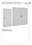
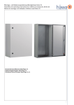
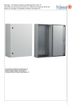
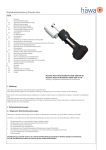
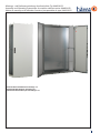
Montage- und Bedienunganleitung Anreihschränke Typ H395/H375
Assembly and Operating Instructions for modular cabinets series H395/H375
Notice de montage et d‘utilisation Armoires juxtaposables de type H395/H375
Deutsch/German/Allemand: Seite/Page 2-4
Englisch/English/Anglais: Seite/Page 5-7
Französisch/French/Français: Seite/Page 8-10
1
Inhalt
Bestimmungszweck2
Allgemeines2
Sicherheitshinweise2
Hinweise für den Transport
3
Hinweise für die Aufstellung
3
Hinweise für die Inspektion, Wartung, Instandsetzung
3
Technische Daten3
Zubehör4
Gewährleistung4
Service4
Bestimmungszweck
Anreihschränke Typ H395/H375 sind als Einzelschrank oder Schrankreihe für die Aufstellung als Standschrank am Boden oder auf Sockel
konzipiert. Sie sind geeignet Komponenten und Geräte der Industrie aufzunehmen.
Ausgelegt nach DIN EN 62208 für den Einsatz im Innenbereich, ist der Typ mit maximal IP56 gegen Staub und starkes Strahlwasser
geschützt – siehe auch Sicherheitshinweise.
Liegen besondere Betriebsbedingungen nach DIN EN 62208, 7.3 vor, sind besondere Vereinbarungen mit dem Hersteller zu treffen!
Allgemeines
Diese Anleitung
-richtet sich an ausgebildete Fachkräfte der Industrie und des Handwerks um Schaltschränke normgerecht auszurüsten, aufzustellen und
anzuschließen.
- ist Bestandteil des Produkts.
Bitte bewahren Sie diese sorgfältig auf. Die gilt gleichfalls für Montage- und Bedienungsanleitungen von Zubehör.
Bei Nichtbeachtung der Anleitung sowie nicht bestimmungsgemäßen Gebrauch übernehmen wir keine Haftung für evtl. Schäden an
oder durch Benutzer und Dritte.
- wird laufend überprüft und gegebenenfalls aktualisiert (technische Änderungen vorbehalten) – siehe http://www.haewa.de/dialogkontakt/download-center.html Die Konformitätserklärung erhalten Sie auf Anfrage bei ihrer Vertriebsniederlassung.
Die Produktbeschreibung ist auf unserer website oder im Katalog Schranksysteme unter der jeweiligen Artikelnummer angegeben.
Der Lieferumfang beinhaltet: 1 Schrank mit Türe(n), Rückwand, 4 Transportösen M12, Dachplatte, 3-geteilte Kabeleinführungsplatte
unten, Wichtige Informationen / Montageanleitung Scharnier, Dichtung für Bodenausschnitt Kabeleinführung sowie 1 Schlüssel 3 mm
Doppelbart, ggf. Montageplatte montiert.
Alle Informationen gelten für den Leerschrank ohne weitere Bearbeitung.
Sicherheitshinweise
Die besonderen Hinweise und technischen Daten der Seiten 2 bis 4 dieser Anleitung sind zu beachten, damit Gefahren für Leib und
Leben bestmöglich minimiert werden können.
Beachten Sie die für ihre Niederspannungs Schaltgerätekombination geltenden Normen und Vorschriften.
Stellen Sie sowohl beim Transport, verbringen an den Aufstellort, Innenausbau, (nachträgliche) Bearbeitung durch geeignete Maßnahmen – idealerweise verschrauben am Boden und ggf. zusätzliche Sicherung durch Gurte oä. - sicher, daß das Produkt nicht kippt.
Beachten Sie ebenfalls Anleitungen des Zubehörs.
Drehmomentangaben sind einzuhalten.
Zum Erhalt der jeweiligen Schutzart (IP) sind alle Öffnungen im Schrank mit Betriebsmittel mindestens derselben Schutzart fachgerecht
zu verschließen.
Sichern Sie bestückte Montageplatten, Schwenkrahmen beim Transport.
Für die Türe(n), Rückwand und Dach sowie die Kabelplatten im Boden ist ein Potenzialausgleich konstruktiv vorhanden. Als zusätzliche
Maßnahme, für einen der Anwendung angepaßten Potenzialausgleich, sind die genannten Anbauteile sowie die Seitenwände (Zubehör)
mit Schutzleiterbolzen oder Bohrungen / Gewindedurchzüge ausgestattet.
Stellen Sie sicher, daß die Umgebungstemperaturen am Aufstellort -25°C und +40°C nicht unter-/überschreiten, kein grober Schmutz
und starke Feuchte vorhanden sind und das Produkt waagrecht steht.
Stellen Sie sicher, daß Türen vollständig geschlossen sind (siehe Hinweise für die Aufstellung).
Die auf Seite 3 angegebenen maximalen statischen Belastungen dürfen nicht überschritten werden.
Beachte: Schränke in Edelstahlausführung sind grundsätzlich für die Freiluftaufstellung geeignet wenn bauseitig für einen Druckausgleich
gesorgt wird.
2
Hinweise für den Transport
Das Produkt ist – vorzusweise auf Palette - stehend zu transportieren. Das Produkt muß während des Transports durch geeignete Maßnahmen gegen Kippen gesichert werden – Lastverteilung, Schwerpunkt beachten. Verwenden Sie Gurte oder Transportbänder in der Art,
daß Türen und/oder Rückwände nicht punktuell belastet werden. Es besteht die Gefahr der Beschädigung der PU-Dichtung. Bei unter
die Schränke montierte Sockel sind grundsätzlich die Vorder- und Rückblende vor dem Anheben (z.B. mittels Stapler) zu entfernen.
Bestückte (Teil-) Montageplatten sind durch zusätzliche Maßnahmen zu sichern: Sperrzahnschrauben M8 unten 3003-9500-08-16,
Einsatz der Mittenbefestigung (Zubehör). Bei Schwenkrahmen sind die Verschlüsse zu verriegeln.
Beim Verwenden der Transportösen (Krantransport) sind die Vorgaben der DIN 580 bezüglich Kraft und Vektor zu beachten. Dies gilt
vor allem für Anreihkombinationen. Hier empfehlen wir die Verwendung eines geeigneten Transportsockel und folgendes Anreihzubehör:
Anreihverbindersatz 0396-7032-01-43, Anreihverbindersatz Standard 0396- / 0376-7002-00-43 sowie Kombinationen aus unserem
Anreihprogramm mit den vorgenannten Varianten.
Hinweise für die Aufstellung
Passen Sie den Türanschlag an notwendige Fluchtwege an.
Das Produkt muß während des Aufstellens durch geeignete Maßnahmen gegen Kippen gesichert werden – Lastverteilung, Schwerpunkt
beachten.
Eine waagrechte Aufstellung ist Voraussetzung für den Erhalt der IP-Schutzart. Dies gilt vor allem bei Schränken mit 2-flgl. überlappenden
Türen!
Die Schränke und eventuell untermontierte Sockel sind konzipiert für das Verschrauben am Boden.
Bei Verwendung von Nivellierfüßen müssen gegebenenfalls Maßnahmen gegen Kippen getroffen werden. Weiter sind in Abhängigkeit
der Breite/Tiefe und Gesamtgewicht eventuell Verstärkungen (Zubehör) zwischen Nivellierfüsse und Schrankboden/Sockel zu montieren.
Vorhandene oder vor Ort eingebrachte Ausbrüche und Bohrungen sind mit Geräten oder sonstigen Einbauteilen in mindestens der IPSchutzart des Schrankes fachmännisch zu verschließen.
Die Stellung des Betätigungseinsatzes (Standard: 3 mm Doppelbart) zeigt an ob die Türe sicher verschlossen ist–waagrecht = geschlossen.
Hinweise für die Inspektion, Wartung, Instandsetzung
Bitte prüfen Sie, gegebenenfalls im Rahmen der Revision, 1 x jährlich
- den Verschluß und Scharniere auf Beschädigung, festen Sitz und einwandfreie Funktion.
- Dichtungen von Türen, Rückwand, Dachplatten, Kabelplatten, Seitenwände auf Beschädigung und ob diese Spalt frei anliegen.
- die Oberfläche auf Beschädigung (führt gegebenenfalls zum Verlust der IP-Schutzart)
- den einwandfreien Zustand der Befestigung.
Säubern Sie verschmutzte Beschlagteile um Schwergängigkeit und Fehlfunktion zu vermeiden.
Tauschen Sie beschädigte Teile aus und verwenden nur häwa Originalteile.
Geben Sie bei der Beschaffung von Ersatzteilen, zu deren Indentifizierung, die Artikelnummer des Schrankes und Auftragsnummer –
siehe Innenseite Türe – an.
Technische Daten
Statische Belastungen (incl. Anheben):
Maximale Belastung inclusive Schrankgewicht – siehe b):
Maximale Belastung der Montageplatte:
Maximale Belastung der Montageplatte in den 2 hintersten Positionen:
Maximale Belastung der Türe 120° und 180°:
13.600 N
7.000 N
9.000 N
1.000 N
Vermerk:
a) Bei Anheben von Einzelschränken ist ein geeignetes Hebezeug zu verwenden, so daß die Transportösen am Schrank gemäß DIN 580
belastet werden – siehe Hinweise für den Transport!
b) Wenn das Anheben mittels der am Schrank befindlichen Transportösen sicher ausgeschlossen wird, z.B. durch Austausch der Ösen
gegen Dachschrauben Art-Nr. 3003-9000-12-25 bzw. 3005-9000-12-25 (Edelstahl A2), erhöht sich die maximale Belastung auf 14.000 N.
c) Sämtliche Angaben gelten unter der Maßgabe der gleichmäßigen Lastverteilung auf der Fläche bzw. im Raum.
IK-Schutzgrad:
IK10
IP-Schutzgrad:
H395* (Stahlblech):1-flgl. Türe: IP55 / 2-flgl. Türe: IP55
H375* (Edelstahl): 1-flgl. Türe: IP55 / 2-flgl. Türe: IP55
* H395/H375, 1-flgl. Türe in Verbindung mit Erweiterungssatz 0396-7056-01-00 für Seitenwände erhöht den Schutzgrad auf IP56
3
Angaben zum Drehmoment:
Untenstehende Angaben wurden einmalig an Serienschränken mit Standardlackierung und aus Edelstahl ermittelt und stellen unter
optimalen Bedingungen (beispielweise gerades Ansetzen Gewinde formender Schrauben) verbindliche Werte dar.
- Rückwand
Befestigen Rückwandhalter am Korpus: 10 Nm
Befestigen Auflaufwinkel an Rückwand unten: 3 Nm
Befestigen Rückwand an Rückwandhalter: 4 Nm
- Dachplatte
Befestigen am Korpus: Stahlblech: 8 Nm / Edelstahl: 2 Nm
- Kabelplatten
Befestigen der Kabelplatte(n) gemäß Lieferumfang oder deren Varianten (siehe Zubehör) am Korpus: Stahlblech 3 Nm / Edelstahl 5 Nm –
nachdem das Gewinde komplett geformt ist.
- Transportösen
Befestigen der Ösen am Korpus: min. 15 Nm – max. 35 Nm
- Montageplatte
Befestigungswinkelsatz für Montageplatte in Dach- und Tragewinkel (Hammerkopf + Mutter M8): 11 Nm
Befestigen der Montageplatte an den Befestigungswinkeln: oben Mutter M8 / unten Schraube M8: 11 Nm
- Verschluß (nach Anschlagwechsel der Türe)
Befestigen Stangenschloß (innen) und Schlüsselschild (außen) an Türblech: Schraube (2x): 2 Nm
Befestigen der Betätigung (Standard 3 mm Doppelbart): Schraube M6: 4 Nm
zusätzlich bei 2-flgl. überlappender Türe:
Befestigen der Abdeckkappe am Schlüsselschild: Schraube (2x): 2 Nm
Befestigen Stangenführung an Türblech: 2 Nm
Befestigen Verschlußhaken an Zarge: 10 Nm
- Scharniere (nach Anschlagwechsel der Türe)
Befestigen Scharnierbock am Korpus: 10 Nm
Befestigen Scharnierlager an Türe: Mutter 4 Nm, Gewindebuchse handfest
- Rohrrahmen der Türe
Befestigen Eckverbinder: Stahlblech: 8 Nm / Edelstahl: 7 Nm
Befestigen 4-kt. Rohr: Stahlblech: 6 Nm / Edelstahl: 7 Nm
Befestigen Auflaufkeil (ab B- 1000 mm): 2 Nm
- Schutzleiter
Befestigen Schutzleiterkabel / -band an Schutzleiterbolzen: Stahlblech: 9 Nm / Edelstahl: 6 Nm
Zubehör
Passendes Zubehör finden Sie unter http://www.haewa.de/loesungen-produkte/schranksysteme.html
Eine Montageanleitung liegt dem Zubehör bei – sofern nicht selbsterklärend.
Gewährleistung
Es gelten unsere AGB. http://www.haewa.de/unternehmen/impressum.html
Für Druckfehler übernehmen wir keine Haftung.
Service
Die für ihren Ort zuständige Vertriebsniederlassung finden Sie auf der letzten Seite.
4
Contents
Application5
General Information5
Safety Instructions5
Instructions for Transport6
Instructions for Installation6
Instructions for Inspection, Maintenance, Repair
6
Technical Data6
Accessories7
Warranty7
Service7
Application
Modular cabinets of the H395/H375 series are designed as free-standing individual cabinets or row of cabinets for installation on the
floor or on a base and are suitable for housing industrial components and devices. Designed in compliance with DIN EN 62208 for interior use, this design is protected against dust and strong water jets with a maximum protection of IP56 – see Safety Instructions for
more details.
Special agreements must be made with the manufacturer in case of special operating conditions being in place as per DIN EN 62208,
7.3!
General Information
These instructions
- are meant for technical staff in industry and trade trained to equip, set up and connect control cabinets in compliance with the applicable standards
- are an integral part of the product.
Please keep them in a safe place for future reference. The same applies to assembly and operating instructions for accessories.
We do not accept liability for any damage caused to or by users or third parties resulting from non-observance of these instructions and/
or improper use.
- are constantly reviewed and updated if necessary (subject to technical changes) – see http://www.haewa.com/dialogue-contact/
download-centre.html
The declaration of conformity can be obtained upon request from our sales office.
You will find the product descriptions on our website or in the cabinet systems catalog under the respective product code.
The scope of delivery includes: 1 cabinet with door(s), rear panel, 4 lifting eyelets M12, top panel, bottom 3-part split cable entry plate,
Important Information / Assembly Instructions for hinge, gasket for the bottom cable-entry cutout as well as a 3-mm double-bit key, fitted
mounting plate ( if required). All details given apply to an empty cabinet without further adaption.
Safety Instructions
The special instructions as well as the technical data specified on pages 5 to 7 of these instructions must absolutely be observed to reduce danger to life and limb as much as possible.
Please take note of the standards and instructions applicable to your combination of low-voltage switchgear.
For any transport including moving to the installation site as well as for interior fittings and any (later) work, take suitable safety measures
to secure the product against tilting, ideally by screwing it into the floor and additionally fixing it with straps or similar, if necessary.
The instructions for accessories must also be observed.
Torque specifications must be adhered to.
To maintain the protection class (IP) specified, all openings in the cabinet must be properly closed using devices of at least the same
protection class.
Secure fitted mounting plates, swing frames for transport.
The design features include a potential equalizer for the door(s), the rear and the top panels and the cable entry plates at the bottom. As
an additional potential equalizing measure, which is appropriate for the application, these parts are fitted with ground studs or drill holes /
threaded holes.
Ensure that the ambient temperatures at the installation site do not fall below -25°C or exceed +40°C, that there is no coarse dirt and
excessive moisture and that the product stands level.
Make sure that the doors are completely closed (see Instructions for Installation).
The maximum static loads as specified on page 6 must not be exceeded.
Note: Cabinets in stainless steel design are only suitable for outdoor installation if pressure compensation is assured (to be provided by
customer).
5
Instructions for Transport
The product must be transported in an upright position – preferably on a pallet. During transport, the product must be suitably secured
against tilting – attention must be paid to load distribution, center of gravity. Use straps or transport belts so as to avoid point loads on the
doors. There is the danger of damaging the PU seals.
If bases are mounted underneath the cabinet (accessories) the front and rear covers must be removed before lifting (e.g. with a forklift).
Fitted (partial) mounting plates must be secured through additional measures: ratchet screws M8 under 3003-9500-08-16.
Installation of center attachment (accessories). Locks of swing frames must be secured.
When using the lifting eyelets (crane transport), the regulations under DIN 580 relating to force and vector must be complied with. This
applies in particular to assembly combinations. Here, we would recommend using a suitable transport base and the following assembly
connection accessories: assembly connector set 0396-7032-01-43, connector set Standard 0396-/0376-7002-00-43 as well as combinations of our assembly connector program with the above-mentioned variants.
Instructions for Installation
Adjust the door hinge according to any necessary escape routes.
The product must be secured against tilting during installation through appropriate measures - attention must be paid to load distribution,
center of gravity.
Horizontal installation is a requirement for maintaining the IP protection class. This applies particularly to cabinets with overlapping double
doors!
The cabinets and the bases mounted underneath, if applicable, are designed for screwing into the floor.
When using leveling feet, measures to prevent tilting must be taken if necessary. In addition, depending on the width/depth and overall
weight, reinforcement brackets (accessories) must be installed between the leveling feet and the bottom of the cabinet/base, if necessary.
Existing openings or drill holes or those made at the site must be properly closed with devices or other fittings that are at least of the same
IP protection class as the cabinet.
The position of the key (standard: 3 mm double-bit) indicates if the door is securely locked – horizontal = locked).
Instructions for Inspection, Maintenance and Repair
Please check yearly in the framework of an inspection, as appropriate:
- lock and hinges for damage, stability and proper functioning,
- door, rear panel, top panel and cable entry plate seals for damage and whether they fit without gaps
- surface for damage (which might lead to loss of the IP protection class)
- perfect condition of the attachment
Clean contaminated fittings to avoid sluggishness and malfunctions.
Exchange damaged parts and use original häwa parts only.
When purchasing spare parts please state the cabinet product code and order number to ensure identification – see inside of door.
Technical data
Static loads (incl. lifting):
Maximum load (incl. weight of cabinet – see b):
Maximum load of mounting plate:
Maximum load of mounting plate in the 2 rearmost positions: Maximum load of doors at 120° and 180°:
13,600 N
7,000 N
9,000 N
1,000 N
Note:
a) When lifting individual cabinets, a suitable lifting gear must be used so that the lifting eyelets on the cabinet are loaded in compliance
with DIN 580 – see Instructions for Transport!
b) If lifting with the help of the lifting eyelets on the cabinet can be safely excluded, e.g. by exchanging the lifting eyelets for top panel
bolts, product code 3003-9000-12-25 or 3005-9000-12-25 (stainless steel A2), then the maximum load will increase to 14,000 N.
c) All specifications apply provided the load is evenly distributed on the surface or in the space.
IK protection class:
IK10
IP protection class:
H395* (sheet steel): single door: IP55 /double door: IP55
H375* (stainless steel): single door: IP55 /double door: IP55
*H395/H375, single door in combination with enhancement kit 0396-7056-01-00 for side panels will increase the protection class to IP56
6
Torque specification:
The specifications stated below have been uniquely determined for standard stainless steel cabinets with standard finish and are
deemed to be binding under optimum conditions (e.g. straight fitting of thread-forming screws).
- Rear panel
Fixing rear panel support to body: 10 Nm
Fixing door support guide to rear panel at the bottom: 3 Nm
Fixing rear panel to rear panel support: 4 Nm
- Top panel
Fixing to body: sheet steel: 8 Nm / stainless steel: 2 Nm
- Cable entry plates
Fixing of cable entry plate(s) according to scope of delivery or variations thereof (see accessories) to body: sheet steel 3 Nm / stainless
steel 5 Nm – after the thread is completely formed
- Lifting eyelets
Fixing lifting eyelets to body: min. 15 Nm – max. 35 Nm
- Mounting plate
Set of mounting brackets for mounting plate at top and bottom support bracket (T-head bolt + nut M8): 11 Nm
Fixing mounting plate to mounting brackets: nut M8 at the top/screw M8 at the bottom: 11 Nm
- Lock (after change of door end stop)
Fixing locking bar (interior) and key plate (exterior) to door panel: screw (2x): 2 Nm
Fixing lock (standard 3-mm double bit): screw M6: 4 Nm
additionally for double overlapping door:
Fixing cover cap to key plate: screw (2x): 2 Nm
Fixing bar guide to door panel: 2 Nm
Fixing retaining hook to door frame: 10 Nm
- Hinges (after opening direction of door has been changed)
Fixing hinge bracket to body: 10 Nm
Fixing hinge bearing to door: nut 4 Nm, threaded bushing finger-tight
- Tubular door frame
Fixing corner joints: sheet steel: 8 Nm / stainless steel: 7 Nm
Fixing square tube: sheet steel: 6 Nm / stainless steel: 7 Nm
Fixing abutting wedge (width – 1,000 mm): 2 Nm
- Protective ground conductor
Fixing grounding cable / grounding straps to ground stud: sheet steel: 9 Nm / stainless steel: 6 Nm
Accessories
You will find suitable accessories under http://www.haewa.com/solutions-products/cabinet-systems/cabinet-systems/group/accessories.
html
Assembly instructions are enclosed with the accessories unless self-explanatory.
Warranty
These instructions are subject to our General Terms and Conditions: http://www.haewa.com/company/imprint.html
We do not accept liability for printing errors.
Service
You will find the location of the sales office responsible for your area on the last page.
7
Sommaire
Utilisation prévue 8
Généralités8
Consignes de sécurité8
Consignes de transport9
Consignes d‘installation9
Consignes pour l‘inspection, la maintenance, la réparation 9
Caractéristiques techniques9
Accessoires10
Garantie10
Service aprés-vente10
Utilisation prévue
Les armoires juxtaposables de type H395/H375 sont conçues comme armoire individuelle ou rangée d‘armoires pour l‘installation debout
sur le sol ou sur un socle.
Ils permettent de recevoir des composants et appareils industriels.
Conçu en respect de DIN EN 62208 pour l‘utilisation en intérieur, le type est protégé au maximum selon IP 56 contre la poussière et les
jets d‘eau fort - voir également les consignes de sécurité.
Si des conditions d‘exploitation spécifiques selon DIN EN 62208 7.3 sont présentes, il faut consulter le fabricant !
Généralités
Cette notice
s‘adresse aux spécialistes qualifiés de l‘industrie et du commerce capables d‘équiper, d‘installer et de raccorder correctement les armoires électriques.
- fait partie intégrante du produit.
Veuillez la conserver soigneusement. Cela vaut également pour les notices de montage et d‘utilisation des accessoires.
En cas de non-respect de la notice et d‘utilisation non conforme, nous déclinons toute responsabilité en cas d‘éventuels dommages
causés sur
ou par les utilisateurs ou des tiers.
- est vérifiée en permanence et actualisée le cas échéant (sous réserve de modifications techniques ) - voir http://www.haewa.fr/dialogue-contact/telechargement.html
Sur demande, votre succursale de distribution vous fournira la déclaration de conformité.
La description du produit est présente sur notre site Internet ou dans le catalogue Systèmes d‘armoire sous la référence correspondante.
Le contenu de la livraison comprend : 1 armoire avec porte(s), paroi arrière, 4 œillets de transport M12, plaque de toit, plaque de guidage de câble divisée en 3 en bas Informations importantes / Notice de montage charnière, joint pour le logement d‘insertion du câble dans
le sol et 1 clé 3 mm à double barbe, le cas échéant, plaque de montage montée.
Toutes les informations s‘appliquent à l‘armoire vide sans autre traitement.
Consignes de sécurité
Les consignes spécifiques et les caractéristiques techniques des pages 8 et 10 de la présente notice doivent être respectées pour minimiser au mieux les dangers pour le corps et la vie.
Veuillez respecter les normes et directives en vigueur pour votre combinaison d‘appareils de commutation basse tension.
Assurez-vous lors du transport, du placement sur le lieu d‘installation, de la mise en place, de la transformation (ultérieure), par des
mesures adaptées,
- idéalement du vissage au sol et si nécessaire, sécurisation supplémentaire par des sangles etc. - que le produit ne bascule pas.
Respectez également les notices des accessoires.
Il faut respecter les indications de couple.
Pour maintenir la classe de protection (IP), il faut fermer correctement toutes les ouvertures dans l‘armoire avec des moyens d‘exploitation
possédant au moins la même classe de protection.
Sécurisez les plaques de montage équipées, les cadres à bascule, lors du transport.
Pour les portes, la paroi arrière et le toit ainsi que les plaques de câble dans le sol, il faut prévoir une liaison équipotentiel.
En tant que mesure supplémentaire pour une liaison équipotentielle ajustée à l‘application, les pièces rapportées et les parois latérales
(accessoires) sont équipées de boulons de raccordement à la terre ou d‘alésages / passages filetés.
Assurez-vous que la température ambiante sur le lieu d‘installation est comprise entre -25°C et +40°C,
qu‘il n‘y a pas de saleté grossière ni de forte humidité et que le produit est horizontal.
8
Assurez-vous que les portes sont entièrement fermées (voir consignes d‘installation).
Les charges statiques maximales indiquées page 9 ne doivent pas être dépassées.
Notez : les armoires en acier inoxydable sont en principe adapté à une installation en plein air lorsqu‘une compensation de pression est
prévue par le client.
Consignes de transport
Le produit doit être transporté debout - de préférence sur une palette. Le produit doit être sécurisé pendant le transport contre le basculement par des mesures adaptées - répartition des charges, observer le centre de gravité.
Utilisez des sangles ou des bandes de transport qui ne sollicitent pas ponctuellement les portes et/ou les parois arrières. Il existe un
risque de dégradation des joints PU. Pour les socles montés sous les armoires, il faut en principe retirer les caches avant et arrière avant
de soulever l‘appareil (avec un chariot à fourche par ex.)
Les plaques de montage (équipées/partiellement) doivent être, le cas échéant, sécurisées par des mesures supplémentaires : Vis à embase crantée M8 en bas 3003-9500-08-16, Utilisation d‘une fixation médiane (accessoires). Pour les cadres à bascule, il faut verrouiller
les fermeture.
En cas d‘utilisation d‘œillets de transport (transport de grue), il faut respecter les exigences de DIN 580 relatives à la force et au vecteur.
Cela vaut notamment pour les combinaisons juxtaposées. Nous recommandons ici l‘utilisation d‘un socle de transport adapté et des
accessoires de juxtaposition suivants : Kit de connexion de juxtaposition 0396-7032-01-43, kit de connexion de juxtaposition standard
0396- / 0376-7002-00-43 et combinaison de notre programme de juxtaposition à partir des variantes précédentes.
Consignes d‘installation
Ajustez la butée de la porte aux issues de secours nécessaires. Le produit doit être sécurisé contre le basculement pendant l‘installation
- répartition des charges, observer le centre de gravité. Une installation horizontale est la condition au maintien de la classe de protection
IP. Cela vaut notamment pour les armoires avec des portes à 2 pans se chevauchant !
Les cadres avec socle éventuellement montés en dessous sont conçus pour un vissage dans le sol. En cas d‘utilisation de pieds de nivellement, il faut également prendre des mesures contre le basculement. De plus, en fonction de la largeur/la profondeur et du poids total, il
faut éventuellement monter des renforts (accessoires) entre les pieds de nivellement et le sol de l‘armoire/le socle.
Les sorties et alésages présents ou réalisés sur place doivent être fermés correctement par des appareils ou autres pièces en respect de
la classe de protection du de l‘armoire au minimum.
La position de l‘insert d‘actionnement (standard : 3 mm double barbe) montre si la porte est bien fermée - horizontal = fermé
Consignes pour l‘inspection, la maintenance, la réparation
Dans le cadre de la révision 1 x an, veuillez vérifier :
- l‘usure des charnières quant aux dégradations, au bon maintien et au fonctionnement sans faille.
- les joints des portes, la paroi arrière, les plaques de toit, les plateaux de câble, les parois latérales du point de vue des dégradations ou
de l‘absence de fentes.
la surface du point de vue des dégradations (conduit également à la perte de la protection IP)
- l‘état parfait de la fixation.
Nettoyez les charnières encrassées pour éviter qu‘elles ne fonctionnent pas bien ou qu‘elles ne présentent une défaillance.
Remplacez les pièces endommagées et utilisez uniquement des pièces originales häwa. Lors de l‘achat de pièces de rechange, pour les
identifier, indiquer la référence de l‘armoire et le numéro de commande – voir intérieur de la porte.
Caractéristiques techniques
Sollicitations statiques (dont soulever) :
Sollicitation maximale avec poids de l‘armoire - voir b) : Sollicitation maximale de la plaque de montage : Sollicitation maximale de la plaque de montage dans les 2 positions les plus arrière : Sollicitation maximale de la porte 120° et 180° : 13 600 N
7 000 N
9 000 N
1 000 N
Remarque :
a) Pour soulever les armoires individuelles, il faut utiliser un outil de levage adapté de sorte à ce que les œillets de transport sur l‘armoire
soient sollicités selon DIN 580 - voir remarques pour le transport !
b) Lorsque le soulèvement avec les œillets de transport se trouvant sur l‘armoire est exclu de manière sûre, par exemple en remplaçant les œillets par des vis de toit réf. 3003-9000-12-25 et 3005-9000-12-25 (acier inoxydable A2), la sollicitation maximale est augmentée à 14.000 N.
c) L‘ensemble des informations s‘appliquent en respect de la répartition régulière des charges sur la surface ou dans la pièce
Classe de protection IK :
IK10
9
Classe de protection :
H395* (tôle d‘acier) : porte à 1 pan : IP55 / porte à 2 pans : IP55
H375* (inox) : porte à 1 pan : IP55 / porte à 2 pans : IP55
* H395/H375, 1 pan Portes en lien avec le kit d‘élargissement 0396-7056-01-00 pour les parois latérales augmentent le degré de protection à IP56
Informations sur le couples
Les informations ci-dessous ont été calculées une fois sur des armoires de série avec mise en peinture standard et acier inoxydable
et elles constituent dans des conditions optimales (par exemple, serrage droit des vis formant des filetages) des valeurs fermes.
- Paroi arrière
Fixer le support de la paroi arrière sur le corps : 10 Nm
Fixer l‘angle d‘entrée sur la paroi arrière en bas : 3 Nm
Fixer la paroi arrière sur le support de la paroi arrière: 4 Nm
- Plaque de toit
Fixer sur le corps : Tôle d‘acier : 8 Nm / Inox : 2 Nm
- Plaques de câble
Fixation des plateaux de câble selon l‘étendue de la livraison ou des variantes (voir accessoires) sur le corps : tôle d‘acier 3 Nm / Inox 5
Nm - après que le filetage est entièrement formé.
- Œillets de transport
Fixer les œillets sur le corps : min. 15 Nm - max. 35 Nm
- Plaque de montage
Kit d‘équerres de fixation pour la plaque de montage dans les angles du toit et de support (tête de marteau + écrou M8) : 11 Nm
Fixer la plaque de montage sur les équerres de fixation : en haut écrou M8 / en bas vis M8 : 11 Nm
- Fermeture (après changement de butée de la porte)
Fixer la serrure à tenon (intérieur) et le panneau à clé (extérieur) sur la tôle de la porte : vis (2x) : 2 Nm
Fixer l‘actionnement (standard 3mm à double barbe) : Vis M6 : 4 Nm
en plus pour les portes à 2 pans à chevauchement :
Fixer le capuchon de couverture sur le panneau de la clé : vis (2x) : 2 Nm
Fixer le guidage à barre sur la tôle de la porte : 2 Nm
Fixer le crochet de fermeture sur le coffrage : 10 Nm
- charnière (après changement de butée de la porte)
Fixer le support de charnière sur le corps : 10 Nm
Fixer le palier de charnière sur la porte : écrou 4N, douille filetée serrée à la main
- Cadre de tube des portes
Fixer Connecteur d‘angle : Tôle d‘acier : 8 Nm / Inox : 7 Nm
Fixation sur 4 bords Tube : Tôle d‘acier : 6 Nm / Inox : 7 Nm
Fixer clavette (à partir de B 1000 mm) : 2 Nm
- Conducteur de protection
Fixer les câbles/bandes avec conducteur de protection sur les boulons Tôle d‘acier : 9 Nm / Inox : 6 Nm
Accessoires
Vous trouverez les accessoires correspondants sur http://www.haewa.fr/solutions-produits/systemes-darmoires/detail/groupe/accessoires.html
Une notice de montage est fournie avec l‘accessoire - sauf si son montage est évident.
Garantie
Nos CGV s‘appliquent http://www.haewa.fr/lentreprise/mentions-legales.html.
Nous ne serions être tenus responsables d‘éventuelles erreurs d‘impression.
Service après-vente
À la dernière page, vous trouverez les succursales de distribution proches de chez vous.
10
11
häwa GmbH
Industriestraße 12
D 88489 Wain
Tel. +49 7353 98460
Fax +49 7353 1050
[email protected]
www.haewa.de
D 08451 Crimmitschau
D 47167 Duisburg
Gewerbegebiet Neumühl
D 63477 Maintal
Dörnigheim
A 4020 Linz
Sachsenweg 3
Theodor-Heuss-Str. 128
Carl-Zeiss-Straße 7
Schmachtl GmbH
Tel. +49 3762 95271/2
Tel. +49 203 346530
Tel. +49 6181 493031
Pummererstraße 36
Fax +49 3762 95278
Fax +49 203 589785
Fax +49 6181 494003
Tel. +43 732 76460
[email protected]
[email protected]
[email protected]
Fax: +43 732 785036
[email protected]
CH 8105 Regensdorf
DK 6400 Sonderborg
E 48450 Etxebarri
F 67140 Eichhoffen
häwa (Schweiz) ag
Eegholm A/S
hawea ibérica, s.l.
häwa France Sarl
Bahnstraße 102
Grundtvigs Allé 165 - 169
Poligono Leguizamón
8 B Rue des Industries
Tel. +41 43 3662222
Tel. +45 73 121212
Calle Guipuzcoa, Pab.9
Tel. +33 3 88088880
Fax +41 43 3662233
Fax: +4573 121213
Tel. +34 944 269521
Fax: +33 3 88088859
[email protected]
[email protected]
Fax: +34 944 261087
[email protected]
[email protected]
SCHRANKSYSTEME
FIN 04130 Sipoo
I 88489 Wain
NL 7500 AC Enschede
P 3730-901 Vale de
Cambra
A-COM OY
häwa Italia
häwa Nederland B.V.
Tecnocon Tecnologia e
Susikuja 6
Industriestraße 12
Postbus 136
Sistemas de Controle, Lda.
Tel. +358 9 2745530
Tel. +49 7353 9846115
Tel. +31 53 4321835
Apartado 106, Codal
Fax +358 9 27455333
Fax +49 7353 1050
Fax +31 53 4303414
Tel. +351 256 420500
[email protected]
[email protected]
[email protected]
Fax +351 256 420501
[email protected]
SE 88489 Wain
SE 25467 Helsingborg
USA Duluth, GA 30097
RUS 88489 Wain
häwa Schweden
Frenna Ab
HAEWA CORPORATION
häwa Russland
Industriestraße 12
Florettgatan 29C
3764 Peachtree Crest Drive
Industriestraße 12
Tel. +49 7353 9846 169
GEHÄUSE
BRANDSCHUTZ
THERMOKOMPONENTEN
LEITUNGSKANÄLE, ZUBEHÖR
Tel. +49 7353 98460
Tel. +46 42 253400
Tel. +1 770 9213272
Fax +49 7353 1050
Fax +46 42 253401
Fax +1 770 9212896
Fax +49 7353 1050
[email protected]
[email protected]
[email protected]
[email protected]
Änderungen vorbehalten / Specifications subject to modifications / Sous réserve de modifications
© häwa, 07/2015 X-FRAME
0395-0000-00-77
SONDERBAUTEN
WERKZEUGE