1
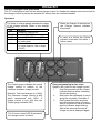
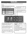
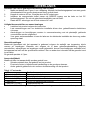
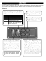
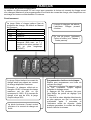
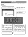
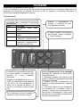
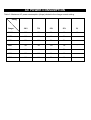
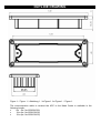
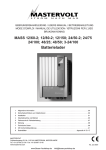
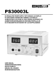
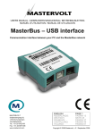
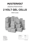
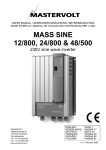
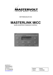
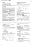
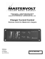
USERS MANUAL / GEBRUIKERSHANDLEIDING
BETRIEBSANLEITING / MODE D’EMPLOI
MANUAL DE UTILIZACION / INSTRUZIONI PER L’USO
Charger Current Control
Remote control for Mastervolt chargers
MASTERVOLT B.V.
Snijdersbergweg 93
1105 AN Amsterdam
The Netherlands
Tel.: +31 20 3422100
Fax.: +31 20 6971006
e-mail: [email protected]
WEB-site: www.mastervolt.com
V1.0-1521104
ENGLISH
Product description and application
The CC is designed to read out the actual charge current of a Mastervolt charger and to set a limit for
the charge current to prevent the external AC source from an overload situation.
Operation
The State of charge gauge indicates the stage
of the charge process. Refer to the charger
manual.
LED
Meaning
1
Charger on, I=max (BULK)
1 and 2
Uout>13.8/27.6/55.2V, I=max
1 till 3
Uout>14.25/28.5/57V, I<max (ABS)
1 till 4
45 min. after start, max. bulk timer,
or I<return amps.
All 5
6 hours after start, max. bulk timer,
or I<return amps for 15min or longer
(FLOAT)
The Output gauge indicates the actual
charge current in relation to the
maximum available charge current.
Example: The used charger is a 12/80.
The maximum charge current is 80A
which corresponds with 100%. If
charge current is only 40A then the
Output gauge indicates 50%.
The Current control LED illuminates if
the charge current is limited.
When the charger is switched on
the Charger present indicator
illuminates.
In case of a failure the Failure
indicator illuminates. See table 1:
failure codes.
Easy programming in thee steps
Steps to set a limit for the charge current:
1.
Hold Set pressed until the Output
indicator starts to blink, indicating
the present setting.
2.
Now press Set repeatedly to scroll
along the set points. See table 2.
3.
Don’t press the button anymore
once the desired value is chosen.
After 3 seconds the value is stored
and the indicator stops blinking.
After a few seconds the actual
charge current is displayed again.
ENGLISH
Installation (see also the manual of the charger used)
1.
Make a cut out using the outline drawings of Figure 1. For good visibility avoid installing the
panel in direct sunlight.
2.
Disconnect the external AC power. Then remove the DC fuses.
3.
Install the communication cable between the QRS232 input of the charger and the CC remote
panel. Refer to the installation manual of the charger.
4.
Place the DC fuses and connect the external power.
Safety regulations and measures
•
Install the product according to the stated instructions.
•
Only allow changes in your electrical system to be carried out by qualified electricians.
•
Connections and safety features must be executed according to the locally applicable
regulations.
•
Do not work on the charger and/or the electrical installation if it is still connected to an external
AC- or DC-source.
Guarantee terms
Mastervolt guarantees that the product has been built according to the legally applicable standards
and stipulations. If you fail to act in accordance with the regulations, instructions and stipulations of
this user’s manual, damage can occur and/or the unit will not fulfill the specifications. This may mean
that the guarantee will become null and void.
The guarantee period is 2 years.
Liability
Mastervolt cannot be held liable for:
•
Damage resulting from the use of the product.
•
Possible errors in the included manual and the consequences of these.
•
Use that is inconsistent with the purpose of the product.
Table 1: Failure codes
LED’s
Failure ind.+ 1 (BULK)
Failure ind.+ 2
Failure ind.+ 3 (ABS)
Failure ind.+ 4
Failure ind.+ 5 (FLOAT)
Meaning
Battery sense error
Charger temperature to high
Short circuit indication, charger will reduce the charge current to 25%
DC error, DC voltage too low or too high
Temperature sense error
See chapter “Trouble shooting” of the manual of your charger to solve the problem.
NEDERLANDS
Product beschrijving en toepassing
De CC wordt gebruikt om de actuele laadstroom weer te geven van een Mastervolt lader en om een
bovengrens in te stellen voor de laadstroom zodat de externe AC niet wordt overbelast.
Bediening
De State of charge indicatie geeft aan in welk
stadium het laadproces is. Zie de
gebruikershandleiding van de lader.
LED
1
1 en 2
1 t/m 3
1 t/m 4
Alle 5
Betekenis
Lader aan, I=max (BULK)
Uuit>13.8/27.6/55.2V, I=max
Uuit>14.25/28.5/57V, I<max (ABS)
45 min. na de start, max. bulk timer,
of I<return amps.
6 uren na de start, max. bulk timer,
of I<return amps voor 15min of
langer (FLOAT)
De Output indicatie geeft de actuele
laadstroom weer ten opzichte van de
maximaal beschikbare laadstroom.
Voorbeeld: de gebruikte lader is een
12/80. De maximale laadstroom is 80A
wat overeenkomt met 100%. Als er
slechts met 40A wordt geladen zal
Output indicatie 50% weergeven.
De Current control indicatie zal
oplichten als er stroombegrenzing
optreedt .
De Charger present indicatie zal
oplichten wanneer de lader is
aangeschakeld.
De Failure indicatie zal in het
geval van een fout oplichten. Zie
tabel 1: Fout codes.
Eenvoudig programmeren in drie
stappen
Stappen om een bovengrens in te stellen
voor de laadstroom:
1. Houd Set ingedrukt totdat de Output
indicatie knippert.
2. Druk herhaaldelijk op Set en loop zo
langs de waardes. Zie tabel 2.
3. Druk niet meer op Set als de gewenste
waarde is geselecteerd. Na 3 seconden zal
de waarde worden opgeslagen. Na een
paar seconden zal de actuele laadstroom
zichtbaar worden.
NEDERLANDS
Installatie (zie ook de gebruikershandleiding van de lader)
1.
Maak met behulp van Figuur 1 een uitsparing. Monteer het bedieningspaneel voor een goede
uitleesbaarheid niet op een plaats waar direct zonlicht komt.
2.
Koppel de externe AC los. Verwijder dan de DC zekeringen.
3.
Installeer de communicatie kabel tussen de QRS232 ingang van de lader en het CC
bedieningspaneel. Zie ook de gebruikershandleiding van de lader.
4.
Plaats de DC zekeringen en sluit de externe AC aan.
Veiligheidsvoorschriften en waarschuwingen
•
Installeer het product volgens de instructies.
•
Laat veranderingen aan uw elektrische installatie alleen door gekwalificeerde elektriciens
uitvoeren.
•
Aansluitingen en beveiligingen moeten in overeenstemming met de plaatselijk geldende
voorschriften worden uitgevoerd.
•
Voer geen werkzaamheden uit aan de lader en de elektrische installatie als deze nog onder
spanning staat.
Garantiebepalingen
Mastervolt garandeert dat het apparaat is gebouwd volgens de wettelijk van toepassing zijnde
normen en bepalingen. Wanneer niet volgens de in deze gebruikershandleiding gegeven
voorschriften, aanwijzingen en bepalingen wordt gehandeld, kunnen beschadigingen ontstaan en/of
het apparaat zal niet aan de specificaties voldoen. Een en ander kan inhouden dat de garantie komt
te vervallen.
De garantie periode is 2 jaar.
Aansprakelijkheid
Mastervolt kan niet aansprakelijk worden gesteld voor:
•
Schade ontstaan door het gebruik van het product.
•
Eventuele fouten in bijbehorende handleiding en de gevolgen daarvan.
•
Ander gebruik geldend als niet conform de bestemming van het product.
Tabel 1: Fout codes
LED’s
Failure ind.+ 1 (BULK)
Failure ind.+ 2
Failure ind.+ 3 (ABS)
Failure ind.+ 4
Failure ind.+ 5 (FLOAT)
Betekenis
Spanningsval detectie fout
Lader temperatuur te hoog
Kortsluitindicatie, lader zal de laadstroom terug regelen naar 25%
DC fout, DC spanning te laag of te hoog
Temperatuursensor fout
Zie het hoofdstuk “Storingen” in de gebruikershandleiding van uw lader om de fout op te lossen.
DEUTSCH
Produktbeschreibung und Anwendung
Der CC wurde so konstruiert, dass er den aktuellen Ladestrom eines Mastervolt Laders anzeigt und
eine Grenze für den Ladestrom festlegt, damit die externe AC-Stromquelle nicht überlastet wird.
Bedienung
Die Messanzeige State of charge gibt den
Stand des Ladeprozesses an. Weitere
Angaben erhalten Sie im Handbuch des
Laders.
LED
1
1und 2
1 bis 3
1 bis 4
Alle 5
Bedeutung
Lader an, I=max (BULK)
Uout>13.8/27.6/55.2V, I=max
Uout>14.25/28.5/57V, I<max (ABS)
45 Min. nach Start, max. BulkZeitgeber oder I<Rück-Amps.
6 Std. nach Start, max. BulkZeitgeber, oder I<Rück-Amps für
15Min o. länger (FLOAT)
Die Messanzeige Output zeigt den
aktuellen Ladestrom im Verhältnis
zum max. verfügbaren Ladestrom an.
Bsp.: Der eingesetzte Lader ist ein
12/80. Der max. Ladestrom beträgt
80A, was 100% entspricht. Wenn
sich der Ladestrom nur auf 40A
beläuft, zeigt die Messanzeige Output
50% an.
Die LED Current control leuchtet
auf, wenn der Ladestrom begrenzt
ist.
Wenn der Lader eingeschaltet
ist,
leuchtet
die
Anzeige
Charger present auf.
Bei einem Fehler leuchtet die
Anzeige Failure auf. Siehe
Tabelle 1: Fehlercodes.
Einfache 3-Stufen-Programmierung
Schritte
zur
Begrenzung
des
Ladestroms:
1. Halten Sie Set gedrückt, bis die
Anzeige Output blinkt und die aktuelle
Einstellung anzeigt.
2. Drücken Sie jetzt wiederholt Set, um
durch die Einstellungspunkte zu scrollen.
Siehe Tabelle 2.
3. Lassen Sie den Knopf nach Wahl des
gewünschten Wertes los. Der Wert wird
nach 3 Sek. gespeichert, die Anzeige
blinkt nicht mehr. Nach einigen Sek. wird
der akt. Ladestrom wieder angezeigt.
DEUTSCH
Installation (beachten Sie die Bedienungsanleitung der Lader)
1.
Installieren Sie den CC an einen Ort ohne direkte Sonneneinstrahlung, um das Display gut
ablesen zu können. Setzen Sie die Einheit in eine Schalttafel mit einer Aussparung
entsprechend den Abmessungen in Abbildung. 1 ein.
2.
Schalten Sie die externe AC-Stromquelle ab. Entfernen Sie dann die DC-Sicherungen.
3.
Verbinden Sie nun mit dem Kommunikationskabel den QRS232-Eingang der Lader mit der
Fernbedienungseinheit. Beachten Sie die Bedienungsanleitung der Lader.
4.
Setzen Sie die DC-Sicherungen ein und schließen Sie den externen Strom an.
Sicherheitsrichtlinien und -maßnahmen
•
Installieren Sie das Produkt gemäß den genannten Anweisungen.
•
Änderungen an Ihrem elektrischen System dürfen nur von qualifizierten Elektrikern
vorgenommen werden.
•
Anschlüsse und Sicherheitsvorkehrungen müssen den lokalen Vorschriften entsprechend
ausgeführt werden.
•
Arbeiten Sie nicht am Lader oder an der Elektroinstallation, solange diese an externe AC- oder
DC-Stromquellen angeschlossen sind.
Garantiebestimmungen
Mastervolt garantiert, dass das Produkt gemäß den geltenden sicherheitstechnischen Richtlinien und
Normen gebaut wurde. Wenn die in dieser Bedienungsanleitung beschriebenen Anweisungen und
Bestimmungen nicht beachtet werden, können Schäden entstehen und das Gerät hält seine
Spezifikationen möglicherweise nicht ein. In diesem Fall kann auch keine Garantie mehr geleistet
werden.
Die Garantiezeit beträgt 2 Jahre.
Haftung
Mastervolt haftet nicht für:
•
durch die Nutzung des Produktes entstandene Schäden.
•
mögliche Fehler in der mitgelieferten Anleitung und die daraus entstehenden Folgen.
•
einen nicht bestimmungsgemäßen Gebrauch.
Tabelle 1: Fehlermeldungen
LED’s
Bedeutung
Fehleranz.+ 1 (BULK)
Batteriemessleitungs-Fehler.
Fehleranz.+ 2
Zu hohe Temperatur im Gerät.
Kurzschluss am DC Ausgang, Ausgangsstrom wird auf ein ¼ des max. möglichen
Fehleranz.+ 3 (ABS)
reduziert.
Fehleranz.+ 4
DC Fehler. Ausgangsspannung zu niedrig oder zu hoch
Fehleranz.+ 5 (FLOAT)
Temperatursensor-Fehler.
Siehe Kapitel “Fehlersuche” im Handbuch Ihres Laders, um das Problem zu lösen.
FRANÇAIS
Description du produit et application
Le tableau de télécommande CC est conçu pour permettre la lecture du courant de charge actuel
d’un chargeur Mastervolt et la programmation d’une limite du courant de charge, afin d’empêcher une
surcharge de la source d’alimentation CA externe.
Fonctionnement
La jauge State of charge indique l’état du
processus de charge. Se référer au Manuel
du Chargeur.
LED
1
1et 2
1à3
1à4
Les 5
Signification
Chargeur on
Uout>13
Uout>14
45 min après démarrage
6 heures après démarrage,
temporis. Bulk max., ou I <
ampères de retour pendant 15
min ou plus longtemps
(FLOAT)
La jauge Output indique la courant de
charge actuel par rapport au courant
de charge disponible maximum.
Exemple : le chargeur utilisé est un
chargeur 12/80. Le courant de charge
maximum est de 80A, ce qui
correspond à 100%. Si le courant de
charge n’est que de 40A, la jauge
Output indique 50%.
La diode lumineuse Current control
s’éclaire si le courant de charge est
limité.
Lorsque le chargeur est allumé,
l’indicateur Charger present
s’éclaire.
En cas de panne, l’indicateur
Failure s’éclaire (voir Tableau 1
: Codes pannes).
Programmation facile en trois étapes :
Etapes pour programmer une limite du
courant de charge :
1. Maintenir le bouton Set appuyé jusqu’à
ce que l’indicateur Output clignote
indiquant le réglage actuel.
2. Appuyer sur Set plusieurs fois pour
faire défiler les points de réglage (voir
Tableau 2).
3. Une fois la valeur désirée sélectionnée,
ne plus appuyer sur Set. La valeur est
mémorisée après 3 secondes et
l’indicateur arrête de clignoter. Après
quelques secondes, le courant de charge
actuel s’affiche à nouveau.
FRANÇAIS
Installation (se référer également au Manuel du Chargeur)
1.
Faire une découpe à l’aide des schémas d’encombrement de la Figure 1. Pour une bonne visibilité,
éviter d’installer le tableau à la lumière directe du soleil.
2.
Déconnecter l’alimentation CA externe, puis retirer les fusibles CC.
3.
Installer le câble de communication entre l’entrée QRS232 du chargeur et le tableau de télécommande
CC. Se référer au Manuel d’installation du chargeur.
4.
Positionner les fusibles CC et raccorder l’alimentation externe.
Règles et mesures de sécurité
•
Installer l’appareil conformément aux instructions spécifiées.
•
N’autoriser de modifications sur votre système électrique que par des électriciens qualifiés.
•
Les branchements et les caractéristiques de sécurité doivent être effectués conformément aux
réglementations locales en vigueur.
•
Ne pas travailler sur le chargeur et/ou l’installation électrique s’ils sont toujours raccordés à
l’alimentation CA ou CC externes.
Conditions de garantie
Mastervolt garantit que l’appareil a été fabriqué conformément aux normes et dispositions légales en
vigueur. Toute installation non conforme aux directives, instructions et spécifications contenues dans
ce manuel utilisateur peuvent endommager l’appareil et/ou l’appareil peut ne pas répondre à ses
spécifications. Ceci pouvant entraîner une annulation de la garantie.
La période de garantie est de deux ans.
Responsabilité
Mastervolt ne peut être tenu pour responsable de :
•
Dommages résultants de l’utilisation de l’appareil.
•
D’erreurs éventuelles contenues dans ce manuel et des conséquences pouvant en résulter.
•
D’utilisations non conformes à l’usage prévu de l’appareil.
Tableau 1 : Codes panne
Diodes
Signification
Ind. panne + 1 (BULK)
Erreur de détection batteries.
Ind. panne + 2
Température trop élevée du chargeur.
Ind. panne + 3 (ABS)
Indication court-circuit - Le chargeur réduira le courant de charge à
25%.
Ind. panne + 4
Erreur CC - La tension CC est trop basse ou trop élevée.
Ind. panne + 5 (FLOAT)
Erreur de détection de température.
Se référer au Chapitre “Localisation des pannes” du Manuel de votre chargeur pour résoudre le
problème.
ESPAÑOL
Descripción y aplicación del producto
La CC está diseñada para leer la corriente de carga real de un cargador Mastervolt y establecer un
límite para la corriente de carga protegiendo a la fuente externa de CA de una situación de
sobrecarga.
Funcionamiento
El indicador State of charge señala el estado
del proceso de carga. Consulte el manual del
cargador.
LED
Significado
1
Cargador on, I=máx (BULK)
1y2
Uout>13,8/27,6/55,2V, I=máx
1 hasta
Uout>14.25/28.5/57V, I<máx (ABS)
3
1 hasta
45
m.
después
arranque,
4
temporizador máx. bulk o I< amps.
retorno
Todo 5
6 h después arranque, temporizador
máx. bulk o I<amps. retorno para
15min o más (FLOAT)
El indicador de Output señala la
corriente de carga real en relación
con la corriente de carga máxima
posible.
Ejemplo: El cargador usado es 12/80.
La corriente de carga máx. es 80A
que corresponde al 100%. Si la
corriente de carga es de sólo 40A, el
indicador de Output señala el 50%.
El LED de Current control se ilumina
si la corriente de carga está limitada.
Cuando el cargador está
activado (on) se ilumina el
indicador Charger present.
En caso de fallo se ilumina el
indicador Failure. Véase la
tabla 1: códigos de fallo.
Programación fácil en tres pasos
Pasos para fijar un límite para la carga:
1. Mantenga pulsado Set hasta que
empiece a parpadear el indicador Output,
indicando el presente ajuste.
2. Pulse Set varias veces para
desplazarse por los valores. Ver tabla 2.
3. No vuelva a pulsar el botón cuando
aparezca el valor deseado. Al cabo de 3
segundos el valor se guarda y cesa el
parpadeo. Luego de unos segundos
vuelve a mostrarse en la pantalla la
corriente de carga real.
ESPAÑOL
Instalación (véase también el manual del Cargador)
1.
Realice un corte usando el plano de proyecto de la Figura 1. Para obtener una buena visibilidad
evite instalar el panel de manera que reciba la luz solar directa.
2.
Desconecte la alimentación de CA externa. Luego quite los fusibles de CC.
3.
Instale el cable de comunicación entre la entrada QRS232 del cargador y el panel remoto de
CC. Consulte el manual de instalación del cargador.
4.
Coloque los fusibles de CC y conecte la alimentación externa.
Normativas y medidas de seguridad
•
Instale el producto según las instrucciones.
•
No permita que electricistas no cualificados realicen cambios en su sistema eléctrico.
•
Las conexiones y los dispositivos de seguridad deben efectuarse según las normativas locales
vigentes.
•
No trabaje con el cargador y/o la instalación eléctrica si todavía está conectado a la CC o CA
externas.
Términos de garantía
Mastervolt garantiza que el producto se ha fabricado de acuerdo con las normas y cláusulas
legalmente aplicables. Si no actúa de acuerdo con las normativas, instrucciones y cláusulas de este
manual del usuario puede provocar daños y/o la unidad no cumplirá las especificaciones. Además,
puede significar la anulación de la garantía.
El periodo de garantía es de 2 años.
Responsabilidad
Mastervolt no se responsabiliza de:
•
Daños provocados por el uso del producto.
•
Posibles errores en el manual incluido y las consecuencias de los mismos.
•
Usos distintos a los indicados para el producto.
Tabla 1: Códigos de fallos
LED
Fallo ind.+ 1 (BULK)
Fallo ind.+ 2
Fallo ind.+ 3 (ABS)
Fallo ind.+ 4
Fallo ind.+ 5 (FLOAT)
Significado
Error sentido batería
Temperatura del cargador excesiva
Indicación cortocircuito, el cargador reducirá corriente de carga al 25%
Error CC, voltaje CC demasiado bajo o demasiado alto
Error sentido temperatura
Véase el capítulo “Solución de problemas” del manual del cargador para solucionar el problema.
ITALIANO
Descrizione del prodotto e modo d’uso
Il CC è progettato in modo da rilevare la corrente di carica attuale di un caricatore Mastervolt e da
impostare un limite per la corrente di carica al fine di impedire un’eventuale situazione di
sovraccarico dell’alimentazione AC esterna
Funzionamento
L’indicatore Stato di carica mostra la fase del
processo di carica. Consultare il manuale del
caricabatterie.
LED
Significato
1
Caricabatterie acceso, I=max
(BULK)
1e2
Uout>13.8/27.6/55.2V, I=max
da 1 a 3
Uout>14.25/28.5/57V,
I<max
(ABS)
da 1 a 4
45 min. dopo l’avvio, cronometro
massa max. o I<ampere di ritorno
Tutti e 5
6 ore dopo l’avvio, cronometro
massa max. o I<ampere di ritorno
per 15min o oltre (FLOAT)
L’indicatore Output mostra la corrente
di carica attuale in rapporto alla
corrente
di
carica
massima
disponibile.
Esempio: Il caricabatterie in uso è un
12/80. La corrente di carica massima
è di 80 A, ciò che corrisponde al
100%. Se la corrente di carica è di
soli 40 A, l’indicatore Output mostra
50%.
Se la corrente di carica è limitata, si
accende il LED Controllo corrente.
Quando il caricabatterie è
acceso, si accende la spia
Caricabatterie presente.
In caso di guasto si accende la
spia Guasto. Vedere la tabella
1: Codici di guasto.
Facile programmazione in tre passaggi
Passaggi per impostare un limite per la
corrente di carica:
1. Mantenere premuto Set finchè la spia
Output comincia a lampeggiare indicando
l’impostazione attuale.
2. Preme ora Set ripetutamente per
scorrere i punti di impostazione. Vedere la
tabella 2.
3. Una volta scelto il valore desiderato,
non premere più il pulsante. Dopo 3
secondi il valore viene memorizzato e la
spia smette di lampeggiare. Dopo alcuni
secondi viene visualizzata nuovamente la
corrente di carica attuale.
ITALIANO
Installazione (vedere anche il manuale del caricabatterie)
1.
Ritagliare usando la sagoma della figura 1. Al fine di assicurare una buona visibilità, evitare di
installare il pannello sotto i raggi diretti del sole.
2.
Scollegare l’alimentazione AC esterna. Togliere quindi I fusibili DC.
3.
Installare il cavo di comunicazione tra l’input QRS232 del caricabatterie e il pannello remoto
CC. Consultare il manuale di installazione del caricabatterie.
4.
Collocare i fusibili DC e collegare l’alimentazione esterna.
Disposizioni e provvedimenti relativi alla sicurezza
•
Installare il prodotto seguendo le istruzioni indicate.
•
Le modifiche del sistema elettrico vanno fatte eseguire solo da elettricisti qualificati.
•
I collegamenti e le caratteristiche di sicurezza vanno eseguiti attenendosi alle disposizioni locali
pertinenti.
•
Non eseguire interventi sul caricabatterie e / o sull’installazione elettrica se l’apparecchio è
ancora collegato alla corrente AC o DC esterna.
Termini di garanzia
La Mastervolt garantisce che il prodotto è stato fabbricato in conformità agli standard e alle
disposizioni applicabili a norma di legge. La mancata osservanza delIe norme, delle istruzioni e delle
disposizioni contenute nel presente manuale può causare danni e / o far sì che l’apparecchio non
risponda alle specifiche. Ciò può comportare il decadere della garanzia.
Il periodo di garanzia è di 2 anni.
Responsabilità
La Mastervolt non può essere ritenuta responsabile nei seguenti casi:
•
Danni risultanti dall’uso del prodotto.
•
Possibili errori del manuale allegato e loro conseguenze.
•
Uso non conforme allo scopo del prodotto.
Tabella 1: codici di guasto
LED
Significato
Spia guasto +1 (BULK)
Errore del senso della batteria
Spia guasto + 2
Temperatura del caricabatterie troppo elevata
Spia guasto + 3 (ABS)
Indicazione di cortocircuito, il caricabatterie ridurrà la corrente di carica al 25%
Spia guasto + 4
Errore DC, voltaggio DC troppo basso o troppo alto
Spia guasto + 5 (FLOAT)
Errore del senso della temperatura
AC POWER CONSUMPTION
Table 2: Maximum AC power consumption (Amps) related to the charge current setting.
Setting
100%
75%
50%
25%
5%
24/100
14A
10A
6A
4A
1A
24/75
11A
8A
4A
3A
-
24/50
7A
5A
3A
2A
-
24/25
4A
3A
2A
1A
-
12/80
6A
4A
3A
2A
-
12/60
5A
3A
2A
1A
-
12/40
3A
2A
2A
1A
-
Charger
OUTLINE DRAWING
Figure 1. / Figuur 1. / Abbildung 1. / la Figure 1. / la Figura 1. / Figura 1.
The communication cable to connect the APC to the Mass Combi is available in the
following length:
•
6m (art. No 6502001030)
•
10m (art. No 6502100100)
•
15m (art. No 6502100150)
Snijdersbergweg 93, 1105 AN Amsterdam, The Netherlands
Tel : + 31-20-3422100
Fax : + 31-20-6971006
e-mail : [email protected]