1
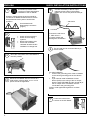
USERS MANUAL / GEBRUIKERSHANDLEIDING / BETRIEBSANLEITING
MANUEL D’UTILISATION / MANUAL DE UTILIZACION / INSTRUZIONI PER L’USO
AC MASTER
Switch mode sine wave inverter
Models 12/200, 12/350, 24/200 & 24/350 - 230V
12/350 - 120V
MASTERVOLT
Snijdersbergweg 93, 1105 AN Amsterdam
The Netherlands
Tel.: +31-20-342 21 00
Fax: +31-20-697 10 06
www.mastervolt.com
ENGLISH:
NEDERLANDS:
DEUTSCH:
FRANÇAIS:
CASTELLANO:
ITALIANO:
PAGE 1
PAGINA 9
SEITE 17
PAGINA 25
PÁGINA 33
PAGINA 41
v 1.0 July 2006
ENGLISH
1
QUICK INSTALLATION INSTRUCTIONS
This section provides a brief
overview of a basic stand alone
installation of the AC Master
5
Connect the battery to the DC input.
Integrate a fuse holder in the positive
battery wire, but do not place the fuse yet.
However; please review the entire manual for
connection of additional features and to ensure
best performance and years of trouble-free
operation.
– black wire
Use isolated tools!
Read safety instructions
(page 3)
+ red wire
2
Disconnect the electrical power:
•
•
•
•
Switch off all consumers,
Switch off all charging
systems.
Remove the battery fuse.
Check with a suitable
voltmeter whether the DC
installation is voltage free.
Connect the red wire to
+, black wire to –.
Incorrect polarity will
damage the AC Master!
6
3
4
Move the main switch of the AC Master to
the OFF position
Mount the AC Master with four screws to a
solid surface. Allow at least 10 cm / 4 inch
space around the apparatus!
For safe installation:
• Connect the grounding point of the AC Master
to the central grounding point of the vehicle/
ship.
• If you need to install a Residual Current
Device (RCD) in the wiring of the AC output,
both the earth (PE/GND) and the neutral (N) of
the AC output of the AC Master must be
connected to the grounding point
Refer to local applicable regulations on these
issues.
7
2
The AC load can be connected directly to
the AC socket.
• Place the inverter fuse.
• Switch on the AC Master.
USER’S MANUAL AC MASTER
PRODUCT DESCRIPTION AND APPLICATION
The Mastervolt inverter “AC Master” converts a DC
voltage to a pure AC sine wave voltage.
SAFETY INSTRUCTIONS
WARNING!
Before using the AC Master, read and
save the safety instructions
• Use the AC Master in accordance with the
instructions and specifications stated in this
manual.
• Connections and safety features must be
executed according to the locally applicable
regulations
• Operation of the AC Master without proper
grounding may lead to hazardous situations!
• Use DC-cables with an appropriate size.
Integrate a fuse in the positive wiring and place it
nearby the battery. Refer to the specifications.
• If the positive and negative wires on the DC-input
(battery) are exchanged, the AC Master will be
damaged. Damage of this kind is not covered by
guarantee. Check whether all connections are
connected correctly before placing the fuse.
• Do not connect the AC-output of the inverter to
an incoming AC source.
• Never open the housing as high voltages may be
present inside!
c AC-output
d LED indicator
ENGLISH
UNPACKING
The delivery consists of the following parts:
• The AC Master (incl. DC cables)
• This user’s manual
After unpacking, check the AC Master for possible
damage. Do not use the AC Master if it is damaged.
If in doubt, contact your supplier.
OUTPUT FREQUENCY
See figure 1. On the front side of the AC Master a
small switch (3) can be found to adjust the output
frequency.
The output frequency is factory set to the correct
value. If necessary, use a small flat-blade screw
driver to adjust the output frequency (50 or 60Hz)
CHOOSING A LOCATION TO INSTALL
• Install the AC Master in a well-ventilated room
protected against rain, vapour, moisture and
dust.
• Ambient temperature: 0 ... 40°C;
• Never use the AC Master at a location where
there is danger of gas or dust explosions
• Mount the AC Master in such a way that
obstruction of the airflow through the ventilation
openings is prevented. No objects must be
located within a distance of 10 cm / 4 inch around
the AC Master.
• Use the included battery cables to connect the
AC Master to the DC supply
• Do not install the AC Master in the same
compartment as the batteries. Do not mount the
AC Master straight above the batteries because
of possible corrosive sulphur fumes.
f Main switch
g Cooling fan
h DC input
Rear side
Front side
Figure 1
i Remote connection j Grounding point
e Output
frequency
3
ENGLISH
USER’S MANUAL AC MASTER
INSTALLATION
Before you start
• Be sure that the output of the supplying source
(battery) is switched off during installation. Also
be sure that no consumers are connected to the
battery during installation, to prevent hazardous
situations.
• Before installing the AC Master make sure the
main switch (figure 1, ref. 4) is set to the OFF
position.
• Check that the battery voltage is the same as the
input voltage of the AC Master (e.g. 24V battery
for a 24V input voltage). Also check that the
output voltage satisfies loading requirements
• A DC fuse holder must be integrated in the
positive wiring. The DC fuse should be placed
last of all.
• Use four Ø4.5mm screws to mount the AC
Master to a solid surface. See figure 3.
Wiring
• DC Wring. Connect DC wiring as shown in figure
2: the black wire (9) NEG (–) to the negative (–)
pole of the power source / battery, the red
terminal (10) POS (+) to the positive (+) pole of
the power source/ battery. Integrate a DC fuse
holder in the positive wiring, but do not place the
fuse yet. Make sure that all DC connections are
tight.
• Chassis ground: Use a cable AWG8 / 6 mm² to
connect the CHASSIS GROUND terminal (8) to
the central ground.
• 120V models (part nr. 28520350): the neutral
connector N of the AC output (1) is
automatically connected to the CHASSIS
GROUND terminal when the inverter is in
operation.
• 230V models: the neutral connector N of the
AC output (1) is not connected to the
CHASSIS GROUND terminal.
• Remote operation switch (option). If you want to
operate the AC Master on a remote location, you
can install a switch as indicated in figure 2. When
the contact is closed, the AC Master is switched
on.
AC Master
f
k Black wire NEG (–)
l Red wire POS (+)
j
Fuse + Fuse holder
Grounding
point
Do not place the fuse
before the entire
installation is completed
Remote operation
switch (option)
Figure 2
4
Battery
USER’S MANUAL AC MASTER
COMMISSIONING AFTER INSTALLATION
1. Check the polarity of the DC-connections. Do
not place the DC fuse if the polarity is not
correct.
2. Place a DC-fuse (see SPECIFICATIONS) in the
fuse holder. When placing this fuse, a spark
may occur, caused by internal capacitors of the
AC Master. This is normal.
3. AC voltage: the load can be plugged into the
AC-output (1) directly. Do not connect the ACoutput of the AC Master to an incoming AC
source.
OPERATION
Switching on:
Move the main switch (4) to “ON”. The AC Master
will start a self-test indicated by two beeps from the
buzzer and a flashing LED indicator (2). This may
last for approximate two seconds. Finally the buzzer
will produce another beep and the AC Master will
switch on, indicated by an illuminating green LEDindicator (2). Now the AC Master is ready to supply
load connected to the AC-output (1).
Switching off:
Move the main switch (4) to the “OFF” position.
Note that switching off the AC Master does not
break the connection to the batteries!
Remote operation:
The AC Master can be operated on a remote
location by means of an optional remote switch.
Move the main switch (4) to the “REMOTE” position.
When the remote contact is closed, the AC Master
is switched on .
LED indicator
The operation mode of the AC Master is made
visible by means of the LED indicator (2)
As long this LED isn’t illuminated red, no failure is
detected: the AC Master is operating normally.
If an error occurs, it is detected by the apparatus
itself: the LED indicator turns red.
Indication of the LED
Meaning
GREEN
RED
Inverter is working normally
Failure. Possible causes:
overload / short circuit
Failure. Possible causes:
DC-input voltage too high
or too low, internal
temperature too high,
RED blinking
ENGLISH
Maintenance
No specific maintenance is required. If necessary,
use a soft clean cloth to clean the AC Master. Never
use any liquids, acids and/or scourers.
Check the wiring on a regular base. Defects such as
loose connections, burnt wiring etc. must be
corrected immediately.
DECOMMISSIONING
Proceed as follows for decommissioning of the AC
Master:
1. Move the main switch (4) to the OFF position.
2. Remove the DC fuse. Be sure that others can
not reverse this action taken.
3. Now the AC Master can be demounted in a save
way.
GUARANTEE TERMS
Mastervolt guarantees that this product was built
according to the legally applicable standards and
stipulations. During production and before delivery
all products are exhaustively tested and controlled.
If you fail to act in accordance with the regulations,
instructions and stipulations in this user’s manual,
damage can occur and/or the product will not fulfil
the specifications. This may mean that the
guarantee will become null and void.
The guarantee is limited to the costs of repair and/or
replacement of the product by Mastervolt only.
Costs for installation labour or shipping of the
defective parts are not covered by this guarantee.
For making an appeal on warranty you can directly
contact your supplier, mentioning your complaint,
application, date of purchase and part number /
serial number.
The standard guarantee period is 2 years.
LIABILITY
Mastervolt cannot be held liable for:
• Possible errors in this manual and the
consequences of these.
• Use that is inconsistent with the purpose of the
product.
5
ENGLISH
USER’S MANUAL AC MASTER
TROUBLE SHOOTING
Consult an installer, if you cannot solve the problem by means of the table below.
Problem
No output voltage, the
LED indicator (2) is off
No output voltage, the
LED indicator (2) is lit red.
No output voltage, the
LED indicator (2) is
blinking red.
Possible cause
Main switch (4) is set to OFF
Main switch (4) is set to REMOTE,
but no remote present
The remote switch is off (if applied)
DC fuse blown
AC Output overloaded
DC input voltage too high
DC input voltage too low (flat battery)
Airflow insufficient
Inverter switches on and
off. LED indicator (2) is
blinking alternately red
and green
DC input voltage too low because of
voltage drop across the DC cables
due to too long or too narrow cables
Flat battery
Loose or corroded connections
Some loads like
televisions and clocks do
not operate correctly
Wrong setting of output frequency
What to do?
Set the main switch (4) in ON position
Set the main switch (4) in ON position
Close the remote operation switch
Replace the fuse
Reduce the load and let the inverter cool down.
The AC Master will switch on again when the
internal temperature has reduced
Check battery voltage; switch off charger. The
inverter will switch on again if the input voltage is
< 15.5V or < 31.0V
Charge the battery. The inverter will switch on
again when the input voltage is > 14.6V or >
29.2V
Check the airflow through the inverter. The
operation of the cooling fan (5) should not be
blocked.
Reduce the length of the DC cables or use cables
with a larger cross section.
Disconnect the load and recharge the battery
Tighten the connections; burnt cables must be
corrected immediately.
Check the specified input frequency of the load
with the output frequency of the AC Master. If
necessary, adjust the output frequency. See
OUTPUT FREQUENCY.
EC DECLARATION OF CONFIRMITY
Manufacturer
Mastervolt
Address
Snijdersbergweg 93, 1105 AN Amsterdam , The Netherlands
Herewith declares that product::
28010200
28010350
AC Master 12/200-230V
AC Master 12/350-230V
28020200
28020350
AC Master 24/200-230V
AC Master 24/350-230V
Is in conformity with the provision of the EC EMC directive 89/336/EEC and amendments 92/31/EEC,
93/68/EEC.
The following harmonised standards have been applied:
Generic emission standard:
EN 55022: 1998+A1: 2000+A2: 2003
Generic Immunity standard:
EN 55024: 1998+A1: 2001+A2: 2003
Harmonic current emissions:
EN 61000-3-2: 2000
Fluctuations and flicker:
EN 61000-3-3: 1995 + A1: 2001
Safety directive 73/23/EEC and amendment 93/68/EEC, with the following standard:
Low voltage standard:
EN 60950: 2000
Amsterdam,
R.J. ter Heide,
General Manager MASTERVOLT
6
USER’S MANUAL AC MASTER
ENGLISH
SPECIFICATIONS
Model AC Master
Part number:
Function of the apparatus:
Manufacturer:
General
Nominal battery voltage:
Nom Power Tamb=25°C, cos phi 1
P30 Power Tamb=40°C, cos phi 1
Max. peak load
Output waveform
Maximum efficiency
Output voltage
Frequency (selectable)
Dimensions
Weight:
Protection degree
Technical
Technology
Shut down voltage low battery
Restart voltage low battery
Shut down voltage high battery
Restart voltage high battery
Maximum allowed ripple on DC
Input current @ nominal load
External DC fuse required
Recommended battery capacity:
DC cable
AC connection*
No load power consumption
(off mode):
No load power consumption
ON @ Unom:
Operating temperature specified
(will meet specified tolerances)
Practical operating temperature
(may not meet specified
tolerances)
Cooling:
Non-operating temperature
(storage temperature)
Relative humidity
Safety:
EMC
E-mark (95/54 CE)
Protections
Protections:
Reversed polarity:
* Other variants upon request
12/200-230V
12/350-230V
24/200-230V
24/350-230V
28010200
28010350
28020200
28020350
Conversion of a DC voltage to a pure AC sine wave voltage
Mastervolt, Amsterdam, the Netherlands
12/350-120V
28520350
12VDC
12VDC
24VDC
200W
350W
200W
200W
350W
200W
400W
700W
400W
True sinewave
90%
86%
93%
230V ±5%
230V ±5%
230V ±5%
50Hz ±0.03Hz 50Hz ±0.03Hz 50Hz ±0.03Hz
74 x 152 x 242 mm / 2.91 x 5.98 x 9.53 inch
1.65kg/3.6Lbs 1.85kg/4.1Lbs 1.65kg/3.6Lbs
IP21
IP21
IP21
24VDC
350W
350W
700W
12VDC
350W
350W
700W
89%
230V ±5%
50Hz ±0.03Hz
84%
120V ±5%
60Hz ±0.03Hz
1.85kg/4.1Lbs
IP21
1.85kg/4.1Lbs
IP21
20.6V (±0.5V)
24.6V (±0.5V)
30.6V (±0.5V)
29.2V (±0.5V)
10.3V (±0.5V)
12.3V (±0.5V)
15.3V (±0.5V)
14.6V (±0.5V)
25A
30A
>40Ah
38A
40A
>80Ah
HF / Switch mode
10.3V (±0.5V) 10.3V (±0.5V) 20.6V (±0.5V)
12.3V (±0.5V) 12.3V (±0.5V) 24.6V (±0,5)
15.3V (±0.5V) 15.3V (±0.5V) 30.6V (±0.5V)
14.6V (±0.5V) 14.6V (±0.5V) 29.2V (±0.5V)
5% RMS
23A
38A
15A
30A
40A
20A
>50Ah
>80Ah
>25Ah
included
Continental European socket CEE-7/7
US/NEMA 5-15
0mA
0mA
0mA
0mA
0mA
0.8A
0.8A
0.5A
0.5A
0.8A
Full specifications at ambient temperature 0 to 40°C (32 to 104°F),
Derating with 5%/°C (3%/°F) at 40 to 60°C (104 to 140°F),
Shutdown at over temperature, auto recover after cooling down
Ambient temperature -25 to 40°C (-13 to 104°F)
Derating with 5%/°C (3%/°F) at 40°C to 60°C (104 to 140°F).
Shutdown at over temperature, auto recover after cooling down
Temperature and load regulated fan
Ambient temperature -30°C to 70°C / -22°F to 158°F
Protected against humidity and condensing air by conformal coating on both sides
of all PCB’s. Max 95% relative humidity, non-condensing.
EN 60950-1
EN55022, EN61000-3-2, EN61000-3-3, EN55024
FCC class A
E13 - 3496
n/a
Overload, short circuit, over / under voltage, over temperature
Internal fuse, reversed polarity may lead to permanent damage
7
ENGLISH
USER’S MANUAL AC MASTER
OUTLINE DRAWING
Figure 3
© Mastervolt BV, Snijdersbergweg 93, 1105 AN Amsterdam, Netherlands
Tel: + 31-20-3422100 Fax: + 31-20-6971006 Email: [email protected]
Mastervolt cannot be held liable for possible errors in the manual and the consequences of these
8