1
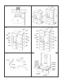
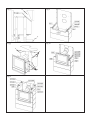
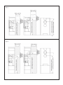
Jøtul FS 161 - GI 160 BF
Jøtul FS 161 - GI 160 BF
Monterings- og bruksanvisning - Norsk
Installation and Operating Instructions - English
Instrucciones para instalación - Español
Manuale di installazione ed uso - Italiano
Figures/Pictures
3
5
7
9
11
Monterings- og bruksanvisningen må oppbevares under hele produktets levetid. These instructions must
be kept for future references.
2
NORSK
Kleberomramming til Jøtul GI 160
For montering av innsats - følg monteringsanvisningen
for produktet. (Kat.nr. 350784)
Jøtul FS 161 - GI 160 BF, er et produkt som kun må fyres
med Naturgass G20/G25 eller konverteres til å fyre med
LPG. Produktet er i samsvar med Forskrift om
gassapparat og utstyr, fastsatt av Direktoratet for Brannog eksplosjonsvern 5. oktober 1994, samt Europeisk
standard CEN EN 613 1998.
Montering og installasjon må utføres av kompetent
person i samsvar med: Montering-, installasjons- og
bruksanvisninger som er vedlagt produktet.
Installasjonen kan først tas i bruk når den er inspisert av
kompetent person, og ferdigattest er gitt.
Et typeskilt av varmebestandig materiale ligger mellom
gassinnsatsens bunn og skjermplate. Det inneholder
følgende informasjon; produsent, adresse, produktnavn,
katalognummer, produksjonsnummer, effekt- og
godkjenningsnummer (etter tildeling).
Teknisk informasjon
Høyde lav versjon:
Høyde høy versjon:
Bredde:
Dybde:
Vekt omramming:
Vekt innsats:
Vekt vedkubbesett:
Vekt kullsett:
Høyde senter røykuttak lav versjon:
høy versjon:
1250 mm
1750 mm
760 mm
455 mm
Lav-265 kg, høy-382 kg
44 kg
1,5 kg
2,1 kg
se fig. 13
se fig. 14
Avstand fra omramming til vegg av brennbare
materialer:
Se fig. 1
Avstand i stråleretning til brennbare materialer :
700 mm
Nødvendige hjelpemidler: Vater, måleband, hammer,
gummihammer, platesaks.
Viktig!
Vær oppmerksom på at steinene kan ta skade ved
hardhendt behandling!
Skulle man være uheldig å få riper i overflaten, kan det
pusses i overflaten med et fint sandpapir. Ved dypere sår
kan det lages en pasta av klebersteinpulver og vannglass,
og sparkle steinen med dette.
Montering av lav versjon (5 høyder) Fig. 2 og 3
Se til at det er fri tilgang til inn- og utluft i skjermplaten.
1. Bestem hvor ildstedet skal stå (i forhold til skorsteinen).
Gulvet inne i omrammingen skal dekkes av en
stålplate (min. 0,9 mm) hvis ildstedet monteres på
gulv av brennbart materiale.
NB. Underlaget må være helt i vater. Max. 2 mm/m
toleranse. Dette er svært viktig for resten av
oppsettingen.
Legg ut alle steinene og følg nøye nummereringen
av steinene i henhold til figurene.
Alle steinene skal være i vater. Bruk evt. små stålbiter
eller sement for å justere høyden.
2. Rad 1 (Z55-Z56-Z57 - fig. 3, 5 og 6):
• Legg ut første rad.
• Fest sidene (Z 56 og Z57) mot frontsteinen (Z55) med
hjelp av klammer (fig. 5 og 6 - 900031).
• Bruk en hammer og slå ned festebrikkene (fig. 5 og 6
-900038). Vær forsiktig når disse slås ned slik at
steinene ikke sprekker.
• Fest stålplaten (fig. 6 - 910241) bak med festeklips
(fig. 6 - 900286).
• Legg bunnplaten (fig. 6 - 900289) på plass i
omrammingen.
• Fest monteringsbrakettene (fig. 6 - 910242) på hver
side av bunnplaten med hjelp av de medfølgende
skruer og muttere.
3. Rad 2 (Z251-Z54-Z53 - fig. 3,6 og 9):
• Sett på plass frontsteinen (Z251) og sidesteinene (Z53
og Z54).
• Legg gassinnsatsen på gulvet. Juster beina. Se fig. 7 A
• Løft opp gassinnsatsen (fig. 7) og plasser den med
beina på monteringsbrakettene (fig. 6 - 910242). Fest
beina til brakettene med hjelp av de medfølgende
skruer og muttere.
• OBS. innsatsen er tung! Sørg for hjelp til løfting.
4. Montering av adapter
• For å kunne montere adapteret (fig. 7 B), må
skjermplatene (fig. 9) på toppen og bak innsatsen taes
av. Fjern først skruene (6 stk) som fester skjermplaten
på toppen og løft av platen. Fjern også skjermplaten
bak som er festet med 8 muttere.
• Dersom det ønskes at ildstedet skal avgi mer varme
til kleberomrammingen, kan skjermplatene rundt
innsatsen fjernes.
• Kontroller at pakningen rundt røykuttaket er intakt.
Det er festet med 4 karrosseriskruer Ø4,2mm.
• Sett på adapteret og mål ut hvor det skal tas hull til
pipe, og tilpass røykrørene.
• Skruene løsnes, og adapteret festes med de samme
4 karrosseriskruene, slik at røret blir stående vannrett.
For å tette alle skjøter mellom røykrørene skal det
brukes varmebestandig tettemiddel.
• For montering av avtrekkssystem, se avsnittet:
”Avtrekkssystem for montering rett ut gjennom
vegg» i hovedmanualet for Jøtul GI 160 BF.
5. Rad 3 og 4 (Z58-Z53-Z54 - fig. 3&10):
• Sett på plass sidesteinene (fig. 3 - Z53 og Z54) og de
3
NORSK
6.
•
•
•
små frontsteinene (fig. 10 - Z58). Fest med brikker og
klammer.
Rad 5 (Z59-Z61-Z60 - fig. 3 og 11):
Sett på plass frontstein (Z59) og sidesteinene (Z60 og
Z61).
Monter avstandsstykkene-se fig. 11 (910249-900288)
og legg på risten. Toppristen må tilpasses (klippes til)
røykrøret.
Legg på topplaten (fig. 3 - Z417) og et evt.
røykhullsdeksel (fig. 3 - Z418).
Montering av høy versjon (7 høyder) Fig. 2 og 4
I tilleggsesken ligger 2 lag med stein for høy versjon (Z52Z53-Z54).
1. Se til at det er fri tilgang til inn- og utluft i
skjermplaten.
2. Bestem hvor ildstedet skal stå (i forhold til pipe) Gulvet
inne i omrammingen skal dekkes av en stålplate (min.
0,9 mm) hvis ildstedet monteres på gulv av brennbart
materiale.
NB. Underlaget må være helt i vater. Max. 2 mm/m
toleranse. Dette er svært viktig for resten av
oppsettingen.
3. Legg ut alle steinene og følg nøye nummereringen
av steinene i henhold til figurene.
4. Legg først ut lag 1 med steiner-se fig. 3 og 6 -(Z52Z53-Z54)
5. Se til at alle steinene er i vater. Bruk evt. små stålbiter
eller sement for å justere høyden.
6. Fest sidene mot frontsteinen med hjelp av klammer
(fig. 5 og 6 - 900031).
7. Bruk en hammer og slå ned festebrikkene (fig. 5 og 6
-900038). Vær forsiktig når disse slås ned slik at
steinene ikke sprekker.
8. Fest stålplaten (fig. 6 - 910241) bak med festeklips
(fig. 6 - 900286)
9. Legg bunnplaten på plass i omrammingen (fig. 6).
10. Fest monteringsbrakettene (fig. 6 - 910242) på hver
side av bunnplaten med hjelp av de medfølgende
skruer og muttere.
11 Den ekstra skjermplaten bak til omrammingen, høy
versjon, skal monteres nederst med den eksisterende
skjermplaten øverst (fig. 14).
12. Sett på plass 2. lag med steiner (Z55-Z56-Z57). Husk å
feste med festebrikker og klammer - Se fig. 4.
13. Sett på plass frontsteinen (Z251) i 3. lag og
sidesteinene (Z53 og Z54). Se fig. 4.
14. Legg gassinnsatsen på gulvet. Juster beinene. Se fig.
7A
15. Løft opp gassinsatsen (fig. 7) og plasser den med beina
på monteringsbrakettene (fig. 6 - 910242 og 900289).
Juster innsatsen slik at den står riktig posisjonert i
forhold til omrammingen. Fest beina godt til
brakettene med hjelp av de medfølgende skruer og
muttere.
OBS. innsatsen er tung! Sørg for hjelp til løfting.
16. Montering av adapter
4
• For å kunne montere adapteret (fig. 7 B), må
skjermplatene (fig. 9) på toppen og bak innsatsen taes
av. Fjern først skruene (6 stk) som fester skjermplaten
på toppen og løft av platen. Fjern også skjermplaten
bak som er festet med 8 muttere.
• Dersom det ønskes at ildstedet skal avgi mer varme
til kleberomrammingen, kan skjermplatene rundt
innsatsen fjernes.
• Kontroller at pakningen rundt røykuttaket er intakt.
Det er festet med 4 karrosseriskruer Ø4,2mm.
• Sett på adapteret og mål ut hvor det skal tas hull til
pipe, og tilpass røykrørene.
• Skruene løsnes, og adapteret festes med de samme
4 karrosseriskruene, slik at røret blir stående vannrett
evt. rett opp og ut med 900 bend. For å tette alle
skjøter mellom røykrørene skal det brukes
varmebestandig tettemiddel.
• For montering av avtrekkssystem, se avsnittet:
”Avtrekkssystem for montering rett ut gjennom
vegg» i hovedmanualet for Jøtul GI 160 BF.
17. Sett på plass 4. og 5. rad med sidesteinene (fig. 4 - Z53
og Z 54) og de små frontsteinene (fig. 10 - Z58). Fest
med brikker og klammer.
18. Sett på plass lag 6 (fig. 4 - Z52- Z53-Z54) fra
tilleggsesken.
19. Sett på plass lag 7 med steiner (fig. 4 - Z59-Z60-Z61).
20. Monter avstandsstykkene-se fig. 10 (910249-900288)
og legg på risten. Toppristen må tilpasses (klippes til)
røykrøret.
21. Legg på topplaten (fig. 4 og 15 - Z417) og et evt.
røykhullsdeksel (fig. 4 og 15 - Z418).
ENGLISH
Soap stone surround for Jøtul GI 160 BF
This product, the Jøtul FS 161 - GI 160 BF may only be used
with Natural Gas or be converted for the use of Butane or
Propane.
The product is in accordance with Regulations for Gas
Appliances and Equipment, established by the European
Standard CEN EN 613 1998.
3.
4.
Assembly and installation must be performed by a qualified
person in accordance with the instructions for assembly,
installation and use enclosed with the product. In the UK
this includes the Gas Safety (Installation & use) Regulations
1998.The installation may only be operated after it has
been inspected by a qualified person and a certificate of
completion has been issued.
5.
A product data plate in heat resistant material can be found
between the gas insert base and the heat shield. The
following information is listed on the data plate:
Manufacturer and address, model number, manufacturing
number, rated heat output, registration number (after
assignment), style, and safety measurements.
8.
Technical information
Height low version
Height high version
Width:
Depth:
Weight of surround:
Weight insert:
Weight log set:
Weight coal set:
Height centre flue outlet low version:
high version:
1,250 mm
1,750 mm
760 mm
455 mm
Low 265 kg, high 382 kg
44 kg
1,5 kg
2,1 kg
fig. 13
fig. 14
Distance from surround to walls of flammable materials:See
fig. 1
Min. distance between furniture and the front of the
fireplace: 700 mm.
Necessary tools: Spirit level, tape measure, hammer, rubber
hammer, sheet metal shears.
Mounting
Remember that the stones can easily be damaged if they
are not handled with care.
If the surface becomes scrathed, it can be polished with
fine sandpaper. Deeper scratches can be repaired by filling
the scratch with a paste made from soap stone powder
and water glass.
1. Make sure that there is adequate ventilation for the
screen plate.
2. Decide where the fireplace will stand (in relation to the
chimney). Flooring within the surround must be covered
6.
7.
by a steel plate (minimum thickness 0.9 mm) if the
fireplace is to stand on a floor of combustible material.
Note! The underlay must be completely level. Max. 2
mm/m tolerance. This is very important for the rest of
the installation process.
Lay out all the stones carefully following the numbering
of the stones as shown in the figures.
First lay out the stones for layer 1. See fig. 3 (Z55-Z56Z57).
Make sure that all the stones are level. If necessary use
small pieces of steel or cement to adjust the height of
the stones.
Attach the side to the front stone with the help of
clamps (fig. 5 - 6, 900031).
Use a hammer to fix the mounting pieces (fig. 5-6,
900038). Be careful not to split the stones when
hammering in the clamps.
Attach the steel plate (fig. 6 - 910241) to the back with
the clips (fig. 6 - 900286).
Installation of the low version (5 heights)
- Fig. 3
1. Fasten the mounting brackets (fig. 7 - 910242) to each
side of the base plate using the nuts and bolts provided.
2. Place the base plate with the mounting brackets in the
surround (fig. 7).
3. Position the second front stone (fig. 3 and 9 - Z251) and
sidestones (Z53 and Z54).
4. Lift the gas insert and place it with the legs on the
mounting brackets.
Note! The product is heavy. Make sure you have
assistance when rising it and putting it in place.
5. Adjust the insert so that it stands in the correct position
in relation to the surround.
6. Fasten the legs to the brackets using the nuts and bolts
provided.
7. Positioning the adapter:
• In order to position the adapter remove the heat
shield on top of the gas insert by unscrewing the 6
screws. Remove also the rear heat shield by
unscrewing the 8 nuts.
• Check that the gasket around the flue pipe is intact.
The flue pipe is fastened using four screws, Ø4.2mm.
• Position the adapter and measure where the hole
for the chimney is to be placed and adjust the flue
pipes.
• Loosen the screws and fasten the adapter with the
same four screws so that the flue pipe is horizontal.
• Use heat-resistant sealant to seal all joins.
• Attach the exhaust hood with 410 mm length to the
adapter.
• Replace the heat shield on top and rear.
8. Place the third and fourth row of side stones in position
(fig. 3 - Z53 and Z 54) and the small front stones
(fig. 12 - Z58). Fix with fixing pieces and clamps.
9. Place row five in position using the front stone (fig. 15 Z59) and the side stones (fig. 14 - Z60).
10. Attach the spacers. See fig. 14 (900287-900288) and
position the grate. The top grate must be adjusted (cut)
5
ENGLISH
to fit the flue pipe.
11. Lay the top plate on top (fig. 15 - Z417) and, if needed, a
flue outlet cover (fig. 15 - Z418).
Installing of the high version
(7 heights) - fig. 4
There are two layers of stones in the additional box (Z52Z53-Z54).
• The extra heat shield at the back of the surround (high
version) is to be mounted at the bottom with the existing
heat shield above. See fig. 16.
• Place stones Z52-Z53-Z54 on the floor (after levelling the
floor). Then follow the same instructions and order of
installation as for the low version. Remember to attach
the fixing pieces and clamps.
• After the insert has been positioned, the first set of
stones (no. Z52-Z53-Z54) from the additional box can be
laid down, then follow the procedure given for the low
version.
6
ESPAÑOL
Mampostería de piedra esteatita para
la Jøtul GI 160 BF
Este producto, Jøtul FS 161 - GI 160 BF sólo se puede utilizar
con gas natural o convertirse para su utilización con butano
o propano.
Este producto cumple la normativa relativa a herramientas
y equipos de funcionamiento por gas, establecida por la
norma europea CEN EN 613 1998.
El montaje y la instalación deben ser realizados por una
persona cualificada de acuerdo con las instrucciones de
montaje, instalación y uso que se incluyen con el producto.
Entre la base de la estufa de inserción de gas y la protección
térmica se encuentra una placa de características del
producto fabricada con material resistente al calor. En esta
placa figura la siguiente información: Fabricante y dirección,
número de modelo, número de fabricación, producción
térmica estimada, número de registro (después de haberla
asignado), estilo y medidas de seguridad.
Información técnica
Versión de altura baja
Versión de altura elevada
Anchura:
Fondo:
Peso - approx.
Altura centro de salida de humos versión baja:
versión alta :
1.250 mm
1.750 mm
760 mm
455 mm
mampostería de
piedra:
versión baja 265 kg,
versión alta 382 kg
44 kg (producto)
1,5 kg (conjunto de
troncos)
2,1 kg (conjunto de
trozos de carbón)
fig. 13
fig. 14
Distancia desde la mampostería de piedra al muro de
material inflamable: vea la figura 1.
La distancia mínima que se debe guardar con el material
combustible en la parte frontal de la estufa es de 700 mm.
Herramientas necesarias: nivel, cinta métrica, martillo,
martillo de goma, cizallas metálicas (tijeras de hojalatero)
Instalación:
Tenga presente que las piedras se pueden dañar fácilmente
si no se manejan con cuidado.
Si la superficie se raya, se puede pulir con papel de lija fino. Los
arañazos más profundos se pueden reparar rellenando el
hueco con una pasta hecha a base de polvo de esteatita y
silicato sódico líquido (vidrio soluble).
1. Compruebe que dispone de ventilación adecuada para
la pantalla.
2. Decida la ubicación de la estufa (en relación con la
chimenea). Si la estufa se va a instalar sobre un suelo
3.
4.
5.
6.
7.
8.
de material inflamable, el suelo del área de
mampostería debe cubrirse con una plancha de acero
de un grosor mínimo de 0,9 mm.
Nota: el suelo sobre el que se va a colocar debe estar
perfectamente nivelado; tolerancia máxima 2 mm/m.
Este detalle es de importancia fundamental para el resto
del proceso de instalación.
Disponga todas las piedras con cuidado siguiendo su
numeración, tal y como se muestra en las figuras.
Coloque primero las piedras para la capa 1. Vea la
figura 3 (Z55-Z56-Z57).
Compruebe que todas las piedras están al nivel. Si es
preciso, utilice trozos pequeños de acero o cemento
para ajustar la altura de las piedras.
Acople el lateral a la piedra frontal con ayuda de
abrazaderas. Vea la figura 5 y 6 (900031).
Utilice un martillo para asegurar las piezas de montaje
(figura 5 y 6 - 900038). Tenga cuidado para no partir las
piedras al golpear las abrazaderas con el martillo.
Acople la plancha de acero a la parte posterior con los
clips (figura 6 - 900286).
Instalación de la versión de poca
altura (5 alturas) - Fig. 3
1. Apriete las abrazaderas de montaje (fig. 5 - 910242)
situadas a cada lado de la placa base mediante las
tuercas y los pernos suministrados.
2. Coloque la placa base con las abrazaderas de montaje
en el hueco de la mampostería (fig. 7).
3. Coloque la segunda piedra frontal (fig. 3 - Z251).
4. Nota: El producto pesa mucho.Necesitará ayuda tanto
para montarlo como para colocarlo en su posición.
Levante la estufa de inserción de gas y colóquela con
las patas sobre las abrazaderas de montaje.
5. Ajuste la estufa de inserción de forma que quede
situada en la posición correcta en el hueco de la
mampostería.
6. Acople las patas a las abrazaderas mediante las tuercas
y los pernos suministrados.
7. Montaje del adaptador:
• Retire los seis tornillos que aseguran la protección
térmica en la parte superior de la estufa de inserción
de gas.
• Saque la placa.
• Afloje la protección térmica en su parte posterior.
Está fijada por medio de tuercas 8xM6
• Compruebe que la junta que rodea la salida de
humos en la parte posterior de la estufa está intacta.
Ésta se sujeta con 4 tornillos de Ø4,2 mm.
• Coloque el adaptador y mida la posición donde
quedará el orificio para la chimenea; ajuste los tubos
de humos.
• Afloje los tornillos y fije el adaptador con los mismos
cuatro tornillos nivelantes de modo que el tubo
quede en posición horizontal.
• Selle todas las juntas con sellante resistente al calor.
• Acople la campana extractora con longitud de
7
ESPAÑOL
conducto de 410 mm al adaptador.
• Vuelva a colocar la protección térmica en la parte
superior y posterior.
8. Coloque la tercera y cuarta filas de piedras laterales en
su sitio (fig. 3 - Z53 y Z 54) y las piedras frontales
pequeñas (fig. 3 - Z58). Asegúrelas con piezas de fijación
y abrazaderas.
9. Coloque la quinta fila en su sitio utilizando la piedra
frontal (fig. 15 - Z59) y las piedras laterales (fig. 14 - Z60).
10. Coloque las piezas de separación. Consulte la fig. 14
(900287-900288) y coloque la parrilla. La parrilla
superior se debe ajustar para que encaje en el tubo de
salida de humos.
11. Coloque la placa superior encima (fig. 15 - Z417) y haga lo
mismo con cualquier cubierta de orificio de humos que
utilice (fig. 15 - Z418).
Instalación de la versión de altura
elevada (7 alturas) - Fig. 4
La caja adicional contiene dos capas de piedras (Z52 - Z 53 Z54).
• La protección térmica adicional situada en la parte
posterior del hueco de la mampostería se debe montar
en la parte inferior con la protección térmica existente
encima. Vea la figura 16.
• Coloque las piedras Z52-Z53-Z54 sobre el suelo (después
de nivelarlo). Siga después las mismas instrucciones y
en el mismo orden de instalación que para la versión de
poca altura. No olvide colocar las piezas de sujeción y
las abrazaderas.
• Una vez que la estufa de inserción esté en su posición,
podrá colocar el primero juego de piedras (Z52-Z53-Z54)
de la caja adicional y seguir después el mismo
procedimiento que para la versión de poca altura.
8
ITALIANO
Intelaiatura in pietra ollare per Jøtul
FS 161 - GI 160 BF
Il Jøtul FS 161 - GI 160 BF deve essere utilizzato solo con gas
naturale oppure può essere convertito per l’impiego di gas
GPL. Questo prodotto è conforme alle disposizioni in
materia di apparecchiature e dispositivi a gas stabilite dal
Direttorato norvegese per la prevenzione di incendi ed
esplosioni in data 5 ottobre 1994 e specificate dallo
standard europeo CEN EN 613 1998.
Il montaggio e linstallazione devono essere effettuati da
un tecnico conformemente alle istruzioni per
l’assemblaggio, l’installazione e luso fornite con il prodotto.
Linstallazione può essere utilizzata solo dopo essere stata
ispezionata da un tecnico e dopo lemissione di un certificato
di completamento.
Tra la base dell’inserto del gas e lo scudo termico si trova
una piastra con i dati del prodotto, in materiale
termoresistente. Sulla piastra informativa si trovano le
seguenti informazioni: Produttore e indirizzo, numero del
modello, numero di serie, uscita di calore prevista, numero
di registrazione (dopo l’assegnazione), modello e misure di
sicurezza. Il timbro di controllo si trova accanto alla piastra.
Dati tecnici
Versione bassa
Versione alta
Larghezza:
Profondità:
Peso circa
Altezza centro di scarico fumi versione bassa:
versione alta:
1.250 mm
1.750 mm
760 mm
455 mm
dell’intelaiatura:
versione bassa 265 kg,
versione alta 382 kg
Prodotto: 44 kg
Chiocchi: 1,5 kg
Carboni: 2,1 kg
fig. 13
fig. 14
Distanza dell’intelaiatura da pareti costruite con materiale
infiammabile: Vedere fig. 1.
La distanza davanti del prodotto alle mobilie: Min. 700 mm
Strumenti necessari: livella ad acqua, metro a nastro, martello,
martello di gomma, cesoie per fogli di metallo (forbici da
lattoniere).
Installazione
Tenere presente che le pietre possono subire danni se non
vengono maneggiate con attenzione.
Se la superficie viene graffiata, può essere rifinita con carta
vetrata sottile. Graffi più profondi possono essere riparati
riempiendoli con una pasta composta da polvere di pietra
ollare e vetro solubile.
1. Verificare che la ventilazione necessaria alla piastra
schermo sia sufficiente.
2. Stabilire la posizione del caminetto, in relazione alla
cappa. Se il camino verrà posizionato su un pavimento
di materiale combustibile, è necessario rivestire il
pavimento intorno all’intelaiatura con una lastra di
acciaio dallo spessore minimo di 0,9 mm.
Nota! L’inclinazione deve essere completamente a
livello. Massimo di tolleranza consentito: 2 mm/m. Questa
accortezza è fondamentale per il resto del processo di
installazione.
3. Disporre tutte le pietre con attenzione, seguendo la
numerazione riportata, come illustrato nelle figure.
4. Disporre innanzitutto le pietre del primo strato. Vedere
fig. 3 (Z55-Z56-Z57).
5. Verificare che tutte le pietre siano a livello. Se necessario,
utilizzare piccole parti di acciaio o cemento per regolare
l’altezza delle pietre.
6. Collegare il bordo della pietra anteriore utilizzando gli
appositi fermi. (Vedere fig. 5 e 6 - 900031).
7. Utilizzare un martello per fissare i pezzi da montare
(fig. 5 e 6 - 900038). Fare attenzione a non colpire le
pietre quando si martellano i fermi.
8. Collegare la lastra di acciaio al retro mediante gli
appositi supporti (fig. 6 - 900286).
Montaggio della versione bassa
(5 altezze) - fig. 3
1. Fissare i supporti di montaggio (fig. 7 - 910242) su ogni
lato della piastra di base utilizzando i dadi e i bulloni
forniti con il prodotto.
2. Posizionare la piastra di base con i supporti di montaggio
nell’intelaiatura (fig. 7).
3. Posizionare la seconda pietra anteriore (fig. 3 - Z251).
4. Sollevare l’inserto del gas e posizionarlo con le gambe
sui supporti di montaggio.
NB.: Il prodotto è pesante. Avrete bisogno di aiuto
durante l’assemblaggio ed il collocamento del prodotto.
5. Posizionare l’inserto e regolarlo alla giusta altezza in
relazione all’intelaiatura.
6. Fissare le gambe ai sostegni utilizzando i dadi e i bulloni
forniti con il prodotto.
7. Posizionare l’addatore
• Rimuovere le sei viti che fissano lo scudo termico
alla parte superiore dell’inserto del gas. Sollevare la
piastra. Rimuovere gli otto dadi che fissano lo scudo
termico alla parte posteriore dell’inserto del gas.
Sollevare la piastra.
9
ITALIANO
• Posizionare l’adattatore, misurare la sezione del foro
in cui dovrà essere collocata la canna fumaria e
adattare i tubi per il fumo.
• Verificare che la guarnizione intorno allo scarico fumi
dietro alla stufa sie integra. Fissarla con l’ausilio di 4
viti con un diametro di 4,2 mm.
• Allentare le viti e fissare l’adattatore con le stesse
quattro viti piatte facendo in modo che il condotto
venga a trovarsi in posizione orizzontale.
• Per sigillare tutte le giunzioni usare un materiale a
tenuta termoresistente.
• La cappa di scarico con il tubo, 410 mm, viene
collegato all’adattatore alla stufa.
• Installare gli schermi termici.
8. Collocare il terzo e quarto strato di pietre laterali (fig. 3
- Z53 e Z 54) e le pietre piccole frontali (fig. 12 - Z58).
Fissarle con i dispositivi di fissaggio e gli appositi fermi.
9. Posizionare correttamente il quinto strato usando la
pietra frontale (fig. 15 - Z59) e le pietre laterali (fig. 14 Z60).
10. Collegare i distanziatori. Vedere fig. 14 (900287-900288)
e posizionare la grata. Adattare (tagliare) la grata
superiore prima di posarla sul condotto del fumo.
11. Posare la piastra superiore (fig. 15 - Z417) e procedere
analogamente con il copri foro per la canna (fig. 15 Z418).
Montaggio della versione alta
(7 altezze) - fig. 4
La scatola aggiuntiva contiene altri due strati di pietre (Z52Z53-Z54).
Lo scudo termico aggiuntivo sul retro dell’intelaiatura
(versione alta) deve essere montato nella parte inferiore,
con lo scudo termico esistente posto nella sezione
superiore. Vedere fig. 16
• Disporre le pietre del secondo strato (Z52-Z53-Z54).
Quindi seguire le stesse istruzioni e la sequenza di
istallazione indicata per la versione bassa. Ricordare di
collegare gli appositi ganci e fermi.
• Dopo aver posizionato l’inserto, è possibile disporre il
primo gruppo di pietre (Z52-Z53-Z54) contenuto nella
scatola aggiuntiva, quindi seguire la procedura indicata
per la versione bassa.
10
Fig. 1
Fig. 2
Fig.3
Fig.4
Fig.5
Fig. 6
11
Fig. 8
B
Fig. 7
A
Fig. 10
Fig.9
A
A
B
Fig. 11
Fig. 13
Fig. 14
14
15
Cat.no. 221244
Draw.no. 4-4330-P00
Jøtul AS, Sept. 2004
Jøtul arbeider kontinuerlig for om mulig å forbedre sine produkter, og vi forbeholder oss retten
til å endre spesifikasjoner, farger og utstyr uten nærmere kunngjøring.
Jøtul pursue a policy of constant product development. Products supplied may therefore differ
in specification, colour and type of accessories from those illustrated and described in the
brochure.
Kvalitet
Jøtul AS arbeider etter et kvalitetssikringssystem basert på NS-EN ISO 9001 for utvikling,
produksjon og salg av ildsteder. Vår kvalitetspolitikk skal gi kundene den trygghet og
kvalitetsopplevelse som Jøtul har stått for siden bedriftens historie startet i 1853.
Quality
Jøtul AS has a quality system that conforms to NS-EN ISO 9001 for product development,
manufacturing, and distribution of stoves and fireplaces. This policy gives our customers quality
and safety piece of mind as a result of Jøtul’s vast experience dating back to when the company
first started in 1853.
Dette ildstedet er kontrollert av:
This product has been controlled by:
Jøtul AS,
P.o. box 1411
N-1602 Fredrikstad,
Norway
________________________
Date:
___________________
Sign: