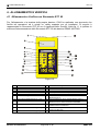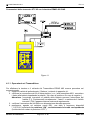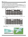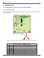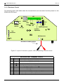
1
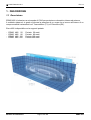
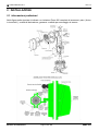
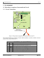
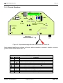
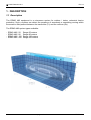
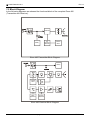
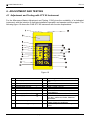
ERMO 482
Barriera a Microonde
per protezioni interne ed esterne
Manuale di Installazione
Internal and external Microwave
protection Barrier
Installation Handbook
Edizione / Edition 2.2
© CIAS Elettronica S.r.l.
Ed. 2.2
INDICE
1. DESCRIZIONE.......................................................................................................................................................................3
1.1 DESCRIZIONE .......................................................................................................................................................................3
1.2 SCHEMA A BLOCCHI .............................................................................................................................................................4
2. INSTALLAZIONE..................................................................................................................................................................5
2.1
2.2
2.3
2.4
2.5
2.6
INFORMAZIONI PRELIMINARI ................................................................................................................................................5
NUMERO DI TRATTE ............................................................................................................................................................6
CONDIZIONI DEL TERRENO ..................................................................................................................................................7
PRESENZA DI OSTACOLI .......................................................................................................................................................7
AMPIEZZA DEI FASCI SENSIBILI ...........................................................................................................................................8
LUNGHEZZA DELLE ZONE MORTE IN PROSSIMITÀ DEGLI APPARATI .....................................................................................9
3. COLLEGAMENTI ...............................................................................................................................................................10
3.1 MORSETTIERE, CONNETTORI E FUNZIONALITÀ DEI CIRCUITI .............................................................................................10
3.1.1 Circuito Trasmettitore ..............................................................................................................................................10
3.1.2 Circuito Ricevitore....................................................................................................................................................12
3.2 COLLEGAMENTO ALL’ALIMENTAZIONE PRINCIPALE .........................................................................................................14
3.2.1 Collegamento all’Alimentazione ..............................................................................................................................14
3.2.2 Collegamento all’Alimentazione di Riserva .............................................................................................................14
3.3 COLLEGAMENTO ALLA CENTRALE .....................................................................................................................................15
3.3.1 Contatti di allarme: Allarme, Manomissione ...........................................................................................................15
4. ALLINEAMENTO E VERIFICA .......................................................................................................................................16
4.1 ALLINEAMENTO E VERIFICA CON STRUMENTO STC 95 .....................................................................................................16
4.1.1 Operazioni sul Trasmettitore....................................................................................................................................17
4.1.2 Operazioni sul Ricevitore .........................................................................................................................................18
5. MANUTENZIONE E ASSISTENZA..................................................................................................................................22
5.1 RICERCA GUASTI ...............................................................................................................................................................22
5.2 KIT ASSISTENZA ...............................................................................................................................................................22
6. CARATTERISTICHE..........................................................................................................................................................23
6.1 CARATTERISTICHE TECNICHE ............................................................................................................................................23
Manuale di Installazione
Pagina 1 di 43
ERMO 482
© CIAS Elettronica S.r.l.
Ed. 2.2
INDEX
1. DESCRIPTION .....................................................................................................................................................................24
1.1 DESCRIPTION .....................................................................................................................................................................24
1.2 BLOCK DIAGRAM ...............................................................................................................................................................25
2. INSTALLATION ..................................................................................................................................................................26
2.1
2.2
2.3
2.4
2.5
2.6
PRELIMINARY INFORMATIONS ...........................................................................................................................................26
NUMBER OF SECTIONS .......................................................................................................................................................27
GROUND CONDITIONS ........................................................................................................................................................28
PRESENCE OF OBSTACLES ..................................................................................................................................................28
AMPLITUDE OF THE SENSITIVE BEAM ................................................................................................................................29
LENGTH OF THE DEAD ZONES NEAR THE EQUIPMENT ........................................................................................................30
3. CONNECTIONS ...................................................................................................................................................................31
3.1 TERMINAL BLOCKS, CONNECTORS AND CIRCUITS FUNCTIONS ..........................................................................................31
3.1.1 Transmitter Circuit ...................................................................................................................................................31
3.1.2 Receiver Circuit ........................................................................................................................................................33
3.2 EQUIPMENT CONNECTION TO THE POWER SUPPLY ............................................................................................................35
3.2.1 Connection to the Power Supply...............................................................................................................................35
3.2.2 Connection of stand-by Battery ................................................................................................................................35
3.3 CONNECTION TO THE CONTROL PANEL..............................................................................................................................36
3.3.1 Alarm contacts: Alarm, Tamper ...............................................................................................................................36
4. ADJUSTMENT AND TESTING.........................................................................................................................................37
4.1 ADJUSTMENT AND TESTING WITH STC 95 INSTRUMENT....................................................................................................37
4.1.1 Transmitter Setting-up ..............................................................................................................................................38
4.1.2 Receiver Setting-up...................................................................................................................................................39
5. MAINTENANCE AND ASSISTANCE ..............................................................................................................................42
5.1 TROUBLESHOOTING ...........................................................................................................................................................42
5.2 MAINTENANCE KITS...........................................................................................................................................................42
6. CHARACTERISTICS ..........................................................................................................................................................43
6.1 TECHNICAL CHARACTERISTICS ...........................................................................................................................................43
Manuale di Installazione
Pagina 2 di 43
ERMO 482
© CIAS Elettronica S.r.l.
Ed. 2.2
1. DESCRIZIONE
1.1 Descrizione
ERMO 482 è la barriera a microonde di CIAS per protezione volumetrica interna ed esterna.
Il suddetto sistema è in grado di rilevare la presenza di un corpo che si muove all’interno di un
campo sensibile instauratosi tra il Trasmettitore (TX) e il Ricevitore (RX).
Ermo 482 è disponibile con le seguenti portate:
-
ERMO
ERMO
ERMO
ERMO
482 / 50
482 / 80
482 / 120
482 / 200
Manuale di Installazione
Portata 50 metri
Portata 80 metri
Portata 120 metri
Portata 200 metri
Pagina 3 di 43
ERMO 482
© CIAS Elettronica S.r.l.
Ed. 2.2
1.2 Schema a Blocchi
Negli schemi a blocchi che seguono sono rappresentati i gruppi funzionali del circuito
Trasmettitore e del circuito Ricevitore della barriera Ermo 482.
Schema a Blocchi circuito Trasmettitore Ermo 482
Schema a Blocchi circuito Ricevitore Ermo 482
Manuale di Installazione
Pagina 4 di 43
ERMO 482
© CIAS Elettronica S.r.l.
Ed. 2.2
2. INSTALLAZIONE
2.1 Informazioni preliminari
Nella figura sotto riportata è indicato un rivelatore Ermo 482 completo di accessori: palo ( diviso
in tronchetti ), scatola di derivazione, ganasce e radiale per ancoraggio al terreno.
.
Manuale di Installazione
Pagina 5 di 43
ERMO 482
© CIAS Elettronica S.r.l.
Ed. 2.2
2.2 Numero di Tratte
Dovendo progettare la protezione con barriere volumetriche di un perimetro chiuso, oltre alle
normali considerazioni di suddivisione del perimetro in un certo numero di tratte che tengano
conto delle necessità gestionali dell'intero impianto, occorre ricordare che è sempre preferibile
installare un numero di tratte pari. Questa considerazione è legata al fatto che le possibili
interferenze reciproche, tra tratte contigue vengono annullate nel caso in cui ai vertici (Incroci)
del poligono risultante dall’installazione stessa, vengano installati due rivelatori aventi lo stesso
nome, cioè due trasmettitori o due ricevitori. E' evidente che ciò può avvenire solo nel caso che
il numero delle tratte sia pari. Qualora non fosse possibile disporne in numero pari, occorrerà
fare alcune attente considerazioni sulle possibili interferenze in modo che possa essere
correttamente scelto il vertice più opportuno dove collocare il Trasmettitore vicino al Ricevitore,
alcuni esempi sono illustrati in figura 1.
ERRATO
CORRETTO
CORRETTO
ERRATO
CORRETTO
CORRETTO
Figura 1
Manuale di Installazione
Pagina 6 di 43
ERMO 482
© CIAS Elettronica S.r.l.
Ed. 2.2
2.3 Condizioni del Terreno
E' sconsigliabile installare gli apparati lungo tratti dove vi sono: erba alta (maggiore di 10 cm),
stagni, corsi d'acqua in senso longitudinale ed in generale tutti quei tipi di terreni la cui
conformazione sia rapidamente variabile.
2.4 Presenza di Ostacoli
Le recinzioni se metalliche e pertanto molto riflettenti, possono causare diversi problemi di
riflessione della microonda, è quindi necessario adottare alcuni accorgimenti:
- la recinzione deve essere accuratamente fissata, in modo che il vento non ne provochi il
movimento;
- dove possibile la tratta non deve essere installata in parallelo alla recinzione, è
necessario creare un angolo rispetto ad essa;
- nel caso in cui il fascio sensibile debba essere delimitato lateralmente da due reti
metalliche, il corridoio tra esse non deve essere inferiore ai 5 m. in quanto il loro
movimento potrebbe creare dei disturbi;
- recinzioni metalliche poste dietro gli apparati possono provocare talvolta distorsioni del
fascio sensibile e quindi dare luogo a zone di ipersensibilità.
Gli alberi, le siepi, i cespugli, la vegetazione in genere richiede una grande attenzione
qualora ve ne sia in prossimità o entro i fasci di protezione.
Questi ostacoli sono elementi variabili sia come dimensione che come posizione, possono infatti
crescere ed essere mossi dal vento.
Figura 2
Pertanto è sconsigliabile tollerare la presenza di detti ostacoli entro le tratte di protezione.
E’ possibile tollerarne la presenza solo a patto che la loro crescita venga limitata mediante una
metodica manutenzione e che il loro movimento venga impedito mediante barriere di
contenimento. All’interno del fascio di protezione, è altresì tollerabile la presenza di tubi, pali ed
Ostacoli vari (illuminazione, camini, ecc) purché non presentino dimensioni eccessive all’interno
dei lobi di protezione. Questi infatti sono la causa di Zone d’Ombra non protette e di Zone di
Ipersensibilità, fonti di falsi allarmi.
Manuale di Installazione
Pagina 7 di 43
ERMO 482
© CIAS Elettronica S.r.l.
Ed. 2.2
2.5 Ampiezza dei Fasci Sensibili
L'ampiezza del Campo Sensibile è in funzione sia del tipo di antenna impiegata, sia della
distanza tra Trasmettitore e Ricevitore, sia dalla regolazione di sensibilità impostata.
Le figure seguenti ci forniscono il diametro a metà tratta del Fascio Sensibile, in funzione della
lunghezza della tratta, nel caso di sensibilità massima e minima per i diversi modelli di
apparecchio impiegati.
Diametro
a metà tratta (m)
Sensibilità
massima
Sensibilità
minima
lunghezza
della tratta (m)
Figura 3 - Diametro della zona sensibile a metà tratta, in spazio libero, per ERMO 482/ 50
Diametro a
metà tratta (m)
Sensibilità
massima
Sensibilità
minima
Lunghezza
della tratta (m)
Figura 4 - Diametro della zona sensibile a metà tratta, in spazio libero, per ERMO 482/ 80120-200
Nota: è necessario ricordare che per l’apparato ERMO 482 la regolazione di Sensibilità deve
essere presa in considerazione per ricavare la dimensione dei fasci sensibili a metà della tratta.
Quanto più alta è la soglia tanto più bassa è la sensibilità e viceversa.
Manuale di Installazione
Pagina 8 di 43
ERMO 482
© CIAS Elettronica S.r.l.
Ed. 2.2
2.6 Lunghezza delle Zone Morte in prossimità degli apparati
La lunghezza delle Zone Morte in prossimità degli apparati è in funzione sia della distanza
dell'apparato stesso dal suolo, sia della sensibilità impostata sul Ricevitore, sia del tipo di
antenna impiegata (figure 5-6). L’Altezza consigliata per installazioni standard è di 80 cm
circa, compatibilmente con le esigenze impiantistiche. La misura è da considerarsi tra il suolo e
il centro dell'apparecchio; con una sensibilità media la distanza minima consigliata per
effettuare l’Incrocio è di 5 m per le barriere da 80-120-200 m e di 3,5 m per le barriere da
50 m
Alte zza d a l S uo lo
d e g li A p pa ra t i (c m )
Se n sibilit à
M ass im a
Se n sibilit à
M in im a
Lung h ezza de lla
Z on a M or ta ( m )
Figura 5 - Lunghezza della zona morta in prossimità degli apparati in funzione dell’altezza dal
centro degli stessi al suolo per ERMO 482/. 50
Altezza dal suolo
degli apparati (cm)
Sensibilità
massima
Sensibilità
minima
Lunghezza della
zona morta (m)
80-85 cm
Figura 6 - Lunghezza della zona morta in prossimità degli apparati in funzione dell’altezza dal
centro degli stessi al suolo per ERMO 482/. 80-120-200
5M
Figura 7 - Sovrapposizione di due fasci sensibili in un incrocio
Manuale di Installazione
Pagina 9 di 43
ERMO 482
© CIAS Elettronica S.r.l.
Ed. 2.2
3. COLLEGAMENTI
3.1 Morsettiere, connettori e Funzionalità dei Circuiti
3.1.1 Circuito Trasmettitore
4 3 21
MS1
8 765 4 3 21
Ampolla
Tamper
DS1
1
2
3
4
OFF
Fusibile
Connettore
di misura
Selettore
Canali
ON
F1
Led Rete
Connettore MW
TX
Faston Rosso
Al Positivo di Batteria
Figura 8 Disposizione topografica dei componenti nel circuito Tx
Nelle seguenti tabelle sono indicate le funzioni delle morsettiere, connettori, selettori e trimmer
presenti sulla scheda ERMO 482 TX:
MORSETTIERA MS1 TRASMETTITORE
Mors. Simbolo
Funzione
Ingresso
tensione
di
alimentazione
alternata 19 V~
1
~
Ingresso tensione di alimentazione alternata 19 V~
2
~
3
4
5
6
7
8
+13,8
+13,8
PR
PR
Manuale di Installazione
Uscita negativo di alimentazione ( 0 V )
Uscita negativo di alimentazione ( 0 V )
Uscita ausiliaria di alimentazione 13,8 V
Uscita ausiliaria di alimentazione 13,8 V
Contatto di Manomissione (NC) + Ampolla
Contatto di Manomissione (C) + Ampolla
Pagina 10 di 43
ERMO 482
© CIAS Elettronica S.r.l.
Ed. 2.2
CONNETTORE DI MISURA PER STC 95
Mors. Simbolo
13,8
1
2
S
3
+9
4
TRASMETTITORE
Funzione
Tensione di alimentazione 13,8 V
Negativo della tensione di alimentazione ( 0 V )
Segnale funzionamento Oscillatore ( 4,5 V )
Alimentazione interna 9 V
LEDS DEL TRASMETTITORE
N°
1
Simbolo
Funzione
RETE
Indicazione Presenza Rete
Default
ON
SELETTORE CANALI DEL TRASMETTITORE
N°
1
Simbolo
Funzione
DS1
Selezione dei Canali di Modulazione ( 1 ÷ 4 )
FUSIBILI DEL TRASMETTITORE
N°
1
Simbolo
Funzione
F1
Fusibile di protezione per batteria (T2A L 250V ritardato)
Manuale di Installazione
Pagina 11 di 43
ERMO 482
© CIAS Elettronica S.r.l.
Ed. 2.2
3.1.2 Circuito Ricevitore
MS1
10 9 8 7 6 5 4 3 2 1
4 3 21
OFF
SEN. INT.
Tamper
ON
DS1
Selettore canali
Ampolla
Led Led
Canale Allarme
Regolazione
Regolazione di Integrazione
di Sensibilità
0.2 Vpp
1
2 Connettore
3
di
4
5 misura
6
7
Fusibile
F1
5V 9V
RX
Led
Rete
Connettore MW
Rag
Faston Rosso
Al Positivo di Batteria
Figura 9 Disposizione topografica dei componenti nel circuito Rx
Nelle seguenti tabelle sono indicate le funzioni delle morsettiere, connettori, selettori e trimmer
presenti sulla scheda ERMO 482 TX:
MORSETTIERA MS1 - RX
Mors
1
2
3
4
5
6
7
8
9
10
Simbolo
~
~
+13,8
NC
C
C
PR
PR
Manuale di Installazione
Funzione
Ingresso tensione di alimentazione alternata 19 V~
Ingresso tensione di alimentazione alternata 19 V~
Uscita ausiliaria negativo di alimentazione ( 0 V )
Uscita ausiliaria negativo di alimentazione ( 0 V )
Uscita ausiliaria di alimentazione 13,8 V
Contatto Relè di Allarme (NC)
Contatto Relè di Allarme (C)
Contatto Relè di Allarme (C)
Contatto di Manomissione (NC) + Ampolla
Contatto di Manomissione (C) + Ampolla
Pagina 12 di 43
ERMO 482
© CIAS Elettronica S.r.l.
Ed. 2.2
CONNETTORE DI MISURA PER STC 95
Mors
1
2
3
4
5
Simbolo
S
ALL
S
0,2
6
+
-
7
RAG
RICEVITORE
Funzione
Soglia di Allarme ( 0,3 V ÷ 9 V )
Segnale di barriera in Allarme
Segnale rivelato normalmente 0 V
Verifica segnale amplificato ( 200 mVpp )
Tensione di alimentazione 13,8 V
Negativo della tensione di alimentazione ( 0 V )
Tensione Regolatore Automatico di Guadagno
LEDS DEL RICEVITORE
N°
1
2
3
Simbolo
Funzione
CAN
Indica il riconoscimento del canale Tx
ALL
Indica Allarme
RETE
Indica se il dispositivo è alimentato con 19 V~
Default
ON
ON
ON
TRIMMERS DEL RICEVITORE
N°
1
2
Simbolo
SEN
INT
Funzione
Regolazione della Sensibilità (minima in senso antiorario)
Regolazione dell’Integrazione (minima in senso antiorario)
SELETTORE
SELETTORE
CANALI
CANALI
DEL RICEVITORE
- RX
N°
1
Simbolo
Funzione
DS1
Selezione dei Canali di Modulazione (1 ÷ 4)
FUSIBILI DEL RICEVITORE
N°
1
Simbolo
Funzione
F1
Fusibile di protezione per batteria (T2A L 250V ritardato)
Manuale di Installazione
Pagina 13 di 43
ERMO 482
© CIAS Elettronica S.r.l.
Ed. 2.2
3.2 Collegamento all’Alimentazione Principale
Gli apparati pur funzionando perfettamente in Corrente Continua a 13,8 V , è preferibile che
siano alimentati in corrente Alternata alla tensione di 19 V~.
3.2.1 Collegamento all’Alimentazione
Il collegamento tra il trasformatore e la rete a 230 V~ dovrà essere effettuato con conduttori la
cui sezione sia di almeno 1,5 mm². Il cavo che porta l’alimentazione dal trasformatore
all’apparecchiatura deve risultare il più breve possibile, deve essere schermato e lo schermo
deve essere collegato a terra. I due conduttori devono essere collegati ai morsetti 1 e 2 della
morsettiera MS1 del circuito Rx, e ai morsetti 1 e 2 della morsettiera MS1 del circuito Tx.
Il trasformatore da utilizzare deve avere le seguenti caratteristiche:
• tensione primaria:
230 V~
• tensione secondaria:
19 V~
• potenza minima:
30 VA
NB: Utilizzare esclusivamente trasformatori di sicurezza certificati secondo le norme vigenti, ad
esempio EN 60950. Deve essere assicurato un ottimo collegamento a terra della carcassa
del trasformatore. Il collegamento del trasformatore alla rete 230 V~ deve essere
effettuato attraverso un idoneo dispositivo di sezionamento che abbia le seguenti
caratteristiche:
• bipolare con distanza minima tra i contatti di 3 mm
• previsto nell’impianto fisso
• facilmente accessibile
In ogni caso occorre attenersi scrupolosamente alle prescrizioni contenute nelle
leggi e nelle normative vigenti in materia di installazioni fisse di apparati collegati
permanentemente alla rete di alimentazione come la Legge 46/90 e la Normativa CEI
64-8.
3.2.2 Collegamento all’Alimentazione di Riserva
All’interno di ciascuna testa è previsto lo spazio per alloggiare una Batteria ricaricabile al
piombo da 12 V - 1.9 Ah (opzionale) . La batteria è normalmente ricaricata dall’alimentatore
interno. Il Fusibile di protezione, contro i sovraccarichi e/o la inversione della batteria, F1 è del
tipo ritardato con una portata di 2A (T2A) Questa batteria, in condizioni d’assenza rete,
consente un’autonomia di circa 12 ore.
NB Gli involucri delle batterie tampone utilizzate, devono avere una classe di autoestinguenza
HB o migliore ( Standard UL 94 ).
Manuale di Installazione
Pagina 14 di 43
ERMO 482
© CIAS Elettronica S.r.l.
Ed. 2.2
3.3 Collegamento alla Centrale
Le connessioni alla Centrale di elaborazione devono essere effettuate mediante cavi schermati.
3.3.1 Contatti di allarme: Allarme, Manomissione
Le uscite degli apparati sono costituite da Relè con contatti normalmente chiusi liberi da
potenziale per la segnalazione degli stati di allarme, manomissione e guasto.
Il contatto d’uscita per l’Allarme è costituito da un Relè statico con portata 100 mA max e
presenta ai morsetti una resistenza complessiva di 35 Ohm.
L’uscita di Manomissione è data dal contatto del Microinterruttore e dal contatto dell’Ampolla
antisposizionamento, con portata 100 mA max.
Le uscite sono attivate per i seguenti motivi:
Uscita di Allarme
1 – Allarme intrusione sul Ricevitore
2 – Allarme canale sul Ricevitore
Uscita di Manomissione
1 – Apertura della testa a microonde Tx o Rx
2 – Sposizionamento (apertura ampolla) Tx o Rx
Nelle protezioni ad Alto Rischio è indispensabile che i rivelatori siano sottoposti con
adeguata periodicità al Test Operativo. In questo modo la centrale di allarme sarà in grado di
riconoscere i tentativi di elusione. Per effettuare il Test operativo della barriera Ermo 482
utilizzare l’accessorio Ermo-Test o disalimentare il trasmettitore.
Manuale di Installazione
Pagina 15 di 43
ERMO 482
© CIAS Elettronica S.r.l.
Ed. 2.2
4. ALLINEAMENTO E VERIFICA
4.1 Allineamento e Verifica con Strumento STC 95
Per l’allineamento e la taratura delle proprie barriere, CIAS ha realizzato uno strumento che
facilita tali operazioni ed è quindi un valido supporto per gli installatori. Di seguito è
rappresentato lo Strumento STC 95 con il significato delle funzioni. Nella fig. 11 è riportato lo
schema d’interconnessione dello Strumento STC 95 alle barriere ERMO 482 CIAS.
Figura 10
1
2
3
4
5
6
7
Connettore 3M
Display LCD
Barra a LED
LED misura alimentazione 13,8 Vcc
LED misura campo rilevato
LED misura Sens.RX / Modulazione TX
LED misura Rag
13
14
15
16
17
18
19
8
9
LED misura alimentazione TX 9 Vcc
LED misura alimentazione RX 5 Vcc
20
21
10
Tasto selezione misure
22
11
Tasto aumento manuale del guadagno
23
12
Tasto diminuz.manuale del guadagno
Manuale di Installazione
Tasto aumento soglia intervento Buzzer
Tasto diminuzione soglia intervento
Tasto attivazione/disattivazione Buzzer
LED segnalazione buzzer attivato
Tasto apertura/chiusura Loop
LED segnalazione Loop aperto
Tasto attivazione/disattivazione misure modulo
Medusa Rx/Tx 2
LED segnalazione misure modulo Medusa Tx/Rx 2
Tasto attivazione/disattivazione misure modulo
MEDUSA RX/TX-ERMO-ERMUSA-MINERMO
LED segnalazione misure modulo MEDUSA RX/TX
ERMO-ERMUSA-MINERMO
Connettore RCA per connettere mediante il cavetto
fornito l’oscilloscopio
Pagina 16 di 43
ERMO 482
© CIAS Elettronica S.r.l.
Ed. 2.2
Connessioni dello strumento STC 95 con le barriere ERMO 482 CIAS
Figura 11
4.1.1 Operazioni sul Trasmettitore
Per effettuare la taratura e il collaudo del Trasmettitore ERMO 482 occorre procedere nel
seguente modo:
1. togliere la calotta di policarbonato ( Radome ) svitando le apposite viti;
2. verificare la connessione dei fili di alimentazione (19 V~) alla morsettiera MS1, connettere
i faston alla batteria rispettando la polarità ( filo rosso al positivo e filo nero al negativo )
Attenzione: l’eventuale inversione di polarità della batteria provoca l’interruzione del
fusibile (F1). Posizionando correttamente i “faston” e sostituendo il fusibile
interrotto (T2A) l’apparecchiatura funzionerà regolarmente.
3. verificare l’accensione del led Rete con alimentazione alternata presente;
4. predisporre, agendo sul selettore canali DS1, una delle 4 frequenze disponibili
( f1,f2,f3,f4 ) spostando in posizione “ON”, esclusivamente la levetta corrispondente
(le altre devono restare in posizione “OFF”).
Manuale di Installazione
Pagina 17 di 43
ERMO 482
© CIAS Elettronica S.r.l.
Ed. 2.2
5. Effettuare l’interconnessione tra lo strumento STC 95 e la barriera ERMO 482 TX, come
indicato in figura 11, inserendo il connettore a 4 pin nel “connettore di misura” del
circuito.
a) Verificare che il led ”Rx/Tx 1” (22) sia acceso. Qualora fosse spento premere il tasto “1”
(21) per accenderlo.
b) Premere il tasto ”c” (10) tante volte quante ne servono per accendere il led “+ 13,8 V”
(4). La tensione letta sul display (2) dovrà essere 13,8 V ± 10 %.
c) Premere il tasto ”c” (10) fino alla accensione del led “9V Tx” (8).
La tensione letta sul display (2) dovrà essere 9 V ± 10 %.
d) Premere il tasto ”c” (10) fino alla accensione del led “sens Rx Tx” (6).
La tensione letta sul display (2) dovrà essere 4,5 V ± 10 %.
4.1.2 Operazioni sul Ricevitore
Per effettuare la taratura e il collaudo del Ricevitore ERMO 482 occorre procedere nel seguente
modo:
1. togliere la calotta plastica ( Radome ) svitando le apposite viti;
2. verificare la connessione dei fili di alimentazione (19 V~) alla morsettiera MS1, connettere
i faston alla batteria rispettando la polarità ( filo rosso al positivo e filo nero al negativo );
Attenzione: l’eventuale inversione di polarità della batteria provoca l’interruzione del
fusibile (F1). Posizionando correttamente i “faston” e sostituendo il fusibile
interrotto (T2A) l’apparecchiatura funzionerà regolarmente.
3. verificare che si accenda il led Rete (con alimentazione presente);
4. predisporre, agendo sul selettore canali, lo stesso canale impostato sulla testa
trasmittente, posizionando in “ON” la corrispondente levetta (le altre devono restare in
posizione “OFF”) (figura 9).
5. effettuare la interconnessione tra lo strumento STC 95 e la barriera ERMO 482 RX,
inserendo il connettore a 7 pin nel “connettore di misura” presente sul circuito ricevitore
come indicato in figura 11.
a) Verificare che il led “Rx/Tx 1” (22) sia acceso. Qualora fosse spento premere il tasto “1”
(21) per accenderlo.
b) Premere il tasto ”c” (10) fino ad accendere il led “+ 13,8 V “ (4). La tensione letta sul
display (2) dovrà essere 13,8 V ± 10 %. Portarsi sulla parte posteriore della testa
ricevente ed accertarsi che la tratta sia libera da ostacoli in movimento Se il preventivo
puntamento a vista degli apparati è stato eseguito si deve verificare sul Ricevitore
l’accensione dei led “CAN” e “ALL” relativi al riconoscimento del canale ed
all’indicazione di non allarme (figura 9).
Allo scopo di ottimizzare il collegamento, si procede all’effettuazione del puntamento
elettronico nel seguente modo.
c) verificare che il led “On” (16) sia spento. Qualora fosse acceso, premere il tasto
“buzzer” (15) per spegnerlo, disattivando in tal modo il buzzer interno al STC 95.
d) Verificare che il led “open” (18) sia acceso. Qualora fosse spento, premere il tasto
“Loop” (17) per accenderlo, ottenendo in tale modo l’apertura del “LOOP”.
Manuale di Installazione
Pagina 18 di 43
ERMO 482
© CIAS Elettronica S.r.l.
Ed. 2.2
e) Premere il tasto ”c” (10) fino ad ottenere l’accensione del led “field Rx” (5).
Verificare che sul display sia leggibile una tensione di circa 6 V ± 10 % e sulla barra a
led (3) sia acceso il led centrale. Qualora il valore di tensione fosse molto diverso e il led
illuminato fosse verso i limiti estremi, premere il tasto “gain ⇑” (11) o il tasto “gain ⇓”
(12) fino a quando si verificherà la condizione precedentemente descritta (accensione
led centrale della barra e indicazione di 6 V ± 10 % sul display).
f) Dopo aver allentato le viti di fissaggio sul palo, ruotare il ricevitore sul piano orizzontale
fino ad ottenere la massima lettura possibile sul display (2).
g) Ripetere l’operazione di puntamento agendo sulla regolazione orizzontale della testa
trasmittente.
h) Ottenuto il migliore puntamento, bloccare il movimento orizzontale sulle due teste.
i) Sbloccare il movimento verticale della testa ricevente e orientarla verso l’alto.
Spostarla lentamente verso il basso fino ad ottenere la massima lettura sul display (2) e
sulla barra a led (3) con le stesse modalità adottate per la regolazione orizzontale.
j) Ripetere il movimento verticale sulla testa TX e, ottenuta la massima lettura, bloccare il
movimento verticale sulle due teste (TX e RX).
k) Premere il pulsante “loop” (17) e verificare lo spegnimento del led “open” (18).
Verificare che a Loop chiuso, dopo un tempo di recupero massimo di due minuti primi, il
valore letto del “field Rx” sul display (2) si porti a 6 V . ± 10 % e si illumini il led
centrale della barra.
La precisione del valore assoluto ( 6 V ).di questa lettura non è molto importante essa
infatti non dipende dal valore assoluto del segnale a MW ricevuto, ma bensì dalla
taratura dello strumento di misura STC 95.
La stabilità di questa lettura è direttamente collegata alla Stabilità del segnale MW
ricevuto, pertanto una lettura instabile sta ad indicare che il segnale ricevuto è
perturbato, occorre quindi accertare che non vi siano nel campo di protezione, oggetti in
movimento, o che il segnale ricevuto sia insufficiente e quindi affetto da rumore.
In caso di dubbio, verificare la reale situazione utilizzando un oscilloscopio collegato al
connettore RCA dell’STC 95 (vedi punto S).
l) Premere il tasto ”c” (10) fino ad ottenere l’accensione del led “Vrag Rx” (7) e verificare
sul display che la tensione letta sia compresa tra 2,5 ÷ 6,5 V .
Questo valore di RAG è direttamente proporzionale alla distanza tra testa trasmittente e
ricevente. Se il valore di Rag letto raggiunge valori superiori a 6 V significa che il
segnale sul ricevitore è molto basso e quindi il collegamento è precario
m) Premere il tasto ”c” (10) fino ad ottenere l’accensione del led “sens RxTx” (6).
Agire sul trimmer SEN ( Sensibilità) fino a leggere sul display un valore compreso tra
0,3 ÷ 9 V ± 10 %. Va tenuto presente che il valore di 0,3 V corrisponde alla
massima sensibilità e il valore 9 V corrisponde alla minima sensibilità.
Le prove di attraversamento vengono di norma, effettuate da una persona che cammina
in posizione eretta ad una velocità di 0.5 m/s. Si consiglia di iniziare le prove con una
impostazione del 50 % di sensibilità (corsa del trimmer) ed una regolazione del 40
% di integrazione (corsa del trimmer). La regolazione di sensibilità deve essere
effettuata per soddisfare le esigenze di protezione dello specifico sito.
Manuale di Installazione
Pagina 19 di 43
ERMO 482
© CIAS Elettronica S.r.l.
Ed. 2.2
Una Sensibilità troppo elevata può causare allarmi impropri.
Si consiglia di non adottare sensibilità maggiori del 75 % (corsa del trimmer) che
corrisponde a circa 1,6 V .
Una Sensibilità troppo bassa può impedire la rivelazione di un intruso di dimensioni
ridotte.
Si consiglia di non adottare sensibilità inferiori al 25 % (corsa del trimmer) che
corrisponde a circa 6,7 V .
n) Regolare il trimmer INT (figura 9) fino ad ottenere l’Integrazione desiderata (massima in
senso orario).
L’Integrazione agisce sulla Velocità di attraversamento.
Le prove di attraversamento vengono di norma effettuate da una persona che cammina
in posizione eretta ad una velocità di 0.5 m/s. La regolazione di integrazione deve essere
effettuata per soddisfare le esigenze di protezione dello specifico sito.
Una regolazione di Integrazione eccessivamente bassa può causare allarmi impropri. Si
consiglia di non adottare un’integrazione superiore al 80 % (corsa del trimmer).
Integrazioni di valore maggiore possono essere favorevolmente adottate quando la
barriera è installata in modo che l’intruso non possa attraversarla correndo (ad esempio
lungo la parete di un edificio).
o) Premere il tasto “buzzer” (15) verificare l’accensione del led “on” (16) che corrisponde
alla abilitazione del buzzer.In assenza di movimenti nel campo di protezione verificare
che il buzzer sia silenziato. Se non lo fosse, premere il tasto “buzzer adj. ⇓” (14) fino ad
ottenere il suo spegnimento Se all’attivazione della funzione il buzzer fosse già
silenziato, agire sul tasto “buzzer adj. ⇑” (13) fino ad ottenere il suo intervento
intermittente, quindi agire leggermente sul tasto “buzzer adj. ⇓” (14) fino a silenziarlo.
p) Effettuare le prove di attraversamento verificando prima il suono intermittente del buzzer
e successivamente il suono continuo e lo spegnimento del led Allarme sulla barriera RX,
che indica l’avvenuto rilevamento dell’allarme.
q) Verificare, inoltre, che in assenza di movimento nel campo protetto il buzzer non entri in
funzione. Se ciò avvenisse, anche in modo discontinuo, significa che il campo è
perturbato.
r)
Per attraversamento di grossi bersagli può verificarsi lo spegnimento anche del led
Canale indicando in tal modo che si è verificata l’interruzione del segnale RF.
La taratura della barriera va effettuata tenendo presenti le esigenze dell’utente, ma
ricordando che un’eccessiva sensibilità si presta alla generazione di allarmi impropri. Per
questo motivo si deve ricercare, di volta in volta, il compromesso più opportuno
E’ importante ricordare che l’Integrazione agisce sulla Velocità d’attraversamento,
mentre la Sensibilità agisce sulla Massa.
Manuale di Installazione
Pagina 20 di 43
ERMO 482
© CIAS Elettronica S.r.l.
Ed. 2.2
s) Lo strumento STC 95, come mostrato in fig.11 dispone di un’uscita RCA (23) che,
mediante il cavetto in dotazione, consente di verificare la forma d’onda del segnale
ricevuto.
Tale verifica richiede un oscilloscopio (qualsiasi modello presente sul mercato).
Un buon collegamento tra testa trasmittente e testa ricevente mostra una forma d’onda
come indicato in figura 13.
50 mV/div.
50 mV/div.
100 us/div.
Figura 13 - Forma d'onda corretta
100 us/div.
Figura 14 - Forma d'onda non corretta (eccessivo rumore)
A = 200 mVpp (+ 10%)
Un cattivo collegamento mostra una forma d’onda come indicato in figura 14.
Si osservi come sulle cuspidi dell’onda quadra sia presente il rumore. Ciò sta a
significare che il segnale ricevuto non è ottimale.
In questo caso ripetere le operazioni di puntamento fino ad ottenere la forma d’onda di
figura 13. Tutti i dati relativi alle misure effettuate in impianto vanno riportati sulle Schede
di Collaudo che sono in dotazione ad ogni barriera. Ciò renderà più semplice l’operazione
di assistenza.
t) Rimontare le calotte ( Radome ) in policarbonato bloccandole uniformemente con le
apposite viti in modo da ottenere una buona tenuta all’acqua.
Manuale di Installazione
Pagina 21 di 43
ERMO 482
© CIAS Elettronica S.r.l.
Ed. 2.2
5. MANUTENZIONE E ASSISTENZA
5.1 Ricerca Guasti
In caso di Falsi Allarmi, verificare i parametri riscontrati durante l’Installazione che saranno stati
registrati nell’apposita Scheda di Collaudo allegata e se si riscontrano delle variazioni che
eccedono i limiti indicati, rivedere i relativi punti nel capitolo 4 “ Allineamento e Verifica “.
Difetto
Led alimentazione spento Tx e/o Rx
Tensione 13,8 V
o 19 V~ non
corretta e/o insufficiente
Led Canale spento
Possibile Causa
Alimentazione +19 V~ non presente
Connessioni interrotte
Trasformatore guasto
Lunghezza e/o sezione cavi non
Adeguata
Selezione canale errata
VRag elevato
Tx o Rx guasti
Movimento od ostacoli nel campo
protetto
Teste disallineate
Teste disallineate
Ostacoli nel campo protetto
Segnale trasmesso insufficiente
Circuito guasto
Ricevitore a microonde guasto
Contatto manomissione aperto
Microinterruttore aperto
Led Allarme spento
Ampolla in posizione errata
Possibile Soluzione
Verifica collegamenti
Effettuare connessioni
Sostituire trasformatore
Ridimensionare nuovamente le
connessioni e/o i cavi
Agendo sul selettore canali del
Ricevitore impostare lo stesso
canale del Trasmettitore
Sostituire parti guaste
Assicurarsi che non vi sia nulla
nel campo protetto
Effettuare il puntamento
Eseguire il puntamento
Rimuovere gli ostacoli
Controllare il Trasmettitore
Sostituire il Ricevitore
Sostituire il Rilevatore a
microonde
Verificare la chiusura del
microinterruttore
Verificare la posizione
dell’ampolla
5.2 Kit Assistenza
I Kit di Assistenza sono costituiti dalla parte di elaborazione circuitale completi di parte a
microonde. L’operazione di sostituzione è molto semplice. Un dato importante da tenere
presente è che il kit d’assistenza è sempre tarato per la massima prestazione, cioè 200 metri di
portata. Ciò per facilitare il compito di chi è chiamato ad effettuare l’assistenza evitandogli
l’onere di disporre di 4 diversi kit in funzione delle portate. In questo modo con un solo kit
d’assistenza l’installatore non ha più l’onere di acquistare delle barriere complete per
l’assistenza ed inoltre rende più semplice e rapida tale operazione.La sostituzione della parte
circuitale e della cavità sia sul Trasmettitore sia sul Ricevitore non altera l’orientamento
della barriera e quindi non obbliga ad effettuare un nuovo puntamento.
Manuale di Installazione
Pagina 22 di 43
ERMO 482
© CIAS Elettronica S.r.l.
Ed. 2.2
6. CARATTERISTICHE
6.1 Caratteristiche Tecniche
Min
CARATTERISTICHE TECNICHE
Nom
Max
Da 9,47 GHz a 10,60 GHz
In accordo con le richieste nazionali
Da 20 a 500 mW e.i.r.p.
In accordo con le richieste nazionali
Frequenza di lavoro
Potenza massima di emissione
Modulazione
Duty-Cycle
Numero di canali
PORTATE
ERMO 482 / 50
ERMO 482 / 80
ERMO 482 / 120
ERMO 482 / 200
On / Off
50 / 50
4
50 m
80 m
120 m
200 m
Tensione d'alimentazione ( V~ )
Tensione d'alimentazione (V )
Corrente assorbita max. TX ( mA~ )
Corrente assorbita max. RX in vigilanza ( mA~ )
Corrente assorbita max. RX in allarme ( mA~ )
Corrente assorbita max. TX ( mA
)
Corrente assorbita max. RX in vigilanza ( mA
Corrente assorbita max. RX in allarme ( mA
Alloggiamento per batteria
17 V~
11,5 V
)
)
19 V~
13,8 V
158 mA
130 mA
120 mA
50 mA
38 mA
32 mA
21 V~
14,8 V
12 V
Contatto relè di allarme intrusione (RX)
Contatto rimozione radome e sposiz.(RX+TX)
100 mA
100 mA
120 mA
SEGNALAZIONI LUMINOSE
Presenza alimentazione - led verde (TX / RX)
Stato di NON Allarme – led verde (RX)
Riconoscimento canale - led verde (RX)
Regolazione della soglia di Sensibilità (RX)
Regolazione della soglia d’Integrazione (RX)
Peso senza batteria (TX)
Peso senza batteria (RX)
Diametro
Profondità comprese le ganasce
Temperatura di lavoro
Livello di prestazione:
Grado di protezione dell'involucro:
Manuale di Installazione
Note
/ 1,9 Ah
C-NC
C-NC
On
On
On
Trimmer
Trimmer
2910 g
2970 g
- 25 °C
3°
IP 55
Pagina 23 di 43
305 mm
280 mm
+ 55 °C
ERMO 482
© CIAS Elettronica S.r.l.
Ed. 2.2
1. DESCRIPTION
1.1 Description
The ERMO 482 equipment is a microwave system for outdoor / indoor volumetric barrier
protection. Such a system can detect the presence of somebody or something moving within
the sensitive field present between the transmitter (Tx) and the receiver (Rx).
The ERMO 482 system types availabile:
-
ERMO 482 / 50
ERMO 482 / 80
ERMO 482 / 120
ERMO 482 / 200
Installation Handbook
Range 50 meters
Range 80 meters
Range 120 meters
Range 200 meters
page 24 to 43
ERMO 482
© CIAS Elettronica S.r.l.
Ed. 2.2
1.2 Block Diagram
In the following diagrams are showed the functional block of the complete Ermo 482
(Transmitter and Receiver).
Modulator
Battery
Low
Freguency
Generator
Channel
Select
Ermo 482 Transmitter Block Diagram
Battery
Channel
Select
Delay
Adjustment
Sensitivity
Adjustment
Ermo 482 Receiver Block Diagram
Installation Handbook
page 25 to 43
ERMO 482
© CIAS Elettronica S.r.l.
Ed. 2.2
2. INSTALLATION
2.1 Preliminary Informations
Due to the various types of ERMO 482 barrier, there are some different kinds of installation and
fixing unit types related to user requirements.
The following picture show ERMO 482 device with accessories: pole segment, transformer
junction box, pole bracket and anti-spin bars.
Installation Handbook
page 26 to 43
ERMO 482
© CIAS Elettronica S.r.l.
Ed. 2.2
2.2 Number of Sections
Having to design protection with volumetric barriers of a closed perimeter, besides having to
split the perimeter within a certain number of sections that take into account the management
need of the entire plant, it must be remembered that it is always preferable to install an even
number of sections. This consideration is bound to the fact that the likely reciprocal
interferences between adjacent sections are annulled should at the vertices of the polygon
(cross), resulting from the installation of the various sections, be installed two equipment with
the same name, two transmitters or two receivers. It is evident that this might occur only if the
number of sections is even. Should it not be possible to have an even number of sections then
some careful considerations must be made on interferences that might likely occur in order to
find the vertex point where retained best to place the transmitter near the receiver. The following
pictures show some typical cases for which the most correct solution is given.
WRONG
RIGHT
RIGHT
WRONG
RIGHT
RIGHT
Figure 1
Installation Handbook
page 27 to 43
ERMO 482
© CIAS Elettronica S.r.l.
Ed. 2.2
2.3 Ground conditions
It is inadvisable to install the equipment along sections with tall grass (more than 10 cm), ponds,
longitudinal waterways, and all those types of grounds whose structure is rapidly mutable.
2.4 Presence of Obstacles
The fences, are generally metallic therefore highly reflecting hence causing various problems,
for this reasons some precautions are suggested:
- first of all, make sure that the fence has been properly fixed in order that the wind does
not move.
- if it is possible the microwave beam shouldn’t be placed in parallel to a metallic fence, is
necessary to create a corner with it.
- metal fences placed behind the equipment night cause distortions to the sensitive beam
especially, and might cause movement detection in unexpected spots, with subsequent
likely generation of false alarms.
- In case of Mw barrier should be installed in a corridor between two metallic fences, the
width of the corridor should be necessary not less to 5 m.
Along the section, within the area of the protection field, are allowed pipes, poles or similar (e.g.,
lamp posts) as long as their dimensions, with respect to the protection beam, are not too
excessive. The trees, hedges, bushes in general, need very great attention if near or within
the protection beams. These obstacles vary in size and position, in fact they grow and they can
be moved by the wind. Therefore, it is absolutely inadvisable to tolerate the presence of the
cited obstacles within the protection sections.
Figure 2
It is possible to tolerate the presence of these elements near the protection sections only if their
growth is limited through routine maintenance, and if their movement is stopped through
containment barriers. Various Obstacles might be present along the protection sections. For
them there is the need to make the same considerations and take the same necessary
precautions adopted for the above cases. This cause of Dead zones not protected and
Hypersensitive zones which cause false alarm.
Installation Handbook
page 28 to 43
ERMO 482
© CIAS Elettronica S.r.l.
Ed. 2.2
2.5 Amplitude of the Sensitive Beam
The amplitude of the Sensitive Beam depends on the distance between the transmitter and the
receiver, and on the sensitivity adjustment set. The figures below state the diameter half-way of
the sensitive beam section (based on the length of the section) in case of maximum and
minimum sensitivity (figure 3 and 4). With a medium sensibility, the minimun space recomend
for corner crossing is 3,5 m. For wall installation, the minimum distance from the wall to the
centre head are 30 cm.
Diameter
Half-Way (m)
Maximum
Sensitivity
Minimum
Sensitivity
Lenght of
the Section (m)
Figure 3 Diameter of sensitive beam at the half-section length (ERMO 482/ 50) (Free
space)
Diameter
Half-Way (m)
Maximum
Sensitivity
Minimum
Sensitivity
Lenght of
the Section (m)
Figure 4 Diameter of sensitive beam at the half-section length (ERMO 482/ 80-120-200)
(Free space)
Remark:
that for the ERMO 482 equipment, the Sensitivity regulation to be considered for obtaining the
dimensions of the sensitivity beams half-way of the section, is that of the alarm threshold.
The higher the threshold the lower the sensitivity, and vice versa.
Installation Handbook
page 29 to 43
ERMO 482
© CIAS Elettronica S.r.l.
Ed. 2.2
2.6 Length of the Dead Zones near the equipment
The length of the Dead Zones near the equipment is based on the distance of the equipment
from ground, on the sensitivity set on the receiver and on the type of antenna used.
With regard to the considerations stated above, and based on plant requirements, the
equipment must be installed at a certain height from ground. In mean plant the height must
be 80 cm. (from the ground and the centre of the equipment).
With medium sensitivity setting, the suggested crossing overlap is 5 m., for the 80-120200 m. versions and 3,5 m. for the 50 m. version.
Installation
Height (cm)
Maximum
Sensitivity
Minimum
Sensitivity
Length of the
Dead Zone
Figure 5 ERMO 482 -50: Dead zone length near the equipment versus installation height.
Installation
Height (cm)
Maximum
Sensitivity
Minimum
Sensitivity
Length of the
Dead Zone (m)
80-85 cm
Figure 6 ERMO 482. 80-120-200: Dead zone length near the equipment versus
installation height.
De
5M
Installation Handbook
ne
D ea d Zo
page 30 to 43
ad
Z on
e
ERMO 482
© CIAS Elettronica S.r.l.
Ed. 2.2
3. CONNECTIONS
3.1 Terminal Blocks, Connectors and Circuits Functions
3.1.1 Transmitter Circuit
The following figure and tables show the terminal block and connector function present on the
ERMO 482 TX board.
4 3 21
MS1
8 765 4 3 21
Bulb
Tamper
Test
Connector
DS1
Channel
1
2
Selector
3
4
OFF
Fuse
F1
Main Led
ON
MW Connector
TX
Red faston to battery positive
Figure 8 Layout of connectors, jumpers, LEDs and presetting in transmitter board
TRASMITTER MS1 TERMINAL BLOCK
Term
1
Symbol
2
3
4
5
6
7
8
Installation Handbook
~
~
13,8
13,8
PR
PR
Function
Mains Ac Power Supply input (19 V~)
Mains Ac Power Supply input (19 V~)
Ground connection
Ground connection
Dc Power Supply input (13,8 V )
Dc Power Supply input (13,8 V )
Tamper relay contact (Normally Closed) + Bulb contact
Tamper relay contact ( Closed) + Bulb contact
page 31 to 43
ERMO 482
© CIAS Elettronica S.r.l.
Ed. 2.2
TRASMITTER TEST CONNECTOR FOR STC 95 INSTRUMENT
Term Symbol
Function
13,8
Power Supply 13,8 V
1
Ground
2
S
Function Oscillator Signal OK ( 4,5 V
3
+9
Internal Power Supply 9 V
4
)
TRASMITTER LEDS
N°
1
Symbol
Function
Main Main presence indication
Default
ON
TRASMITTER CHANNELS SWITCH
N°
1
Symbol
Function
DS1
Channel Selector ( 1 ÷ 4 )
Default
TRASMITTER FUSES
N°
1
Symbol
Function
F1
Power supply protection fuse battery 13,8 V
Installation Handbook
page 32 to 43
ERMO 482
© CIAS Elettronica S.r.l.
Ed. 2.2
3.1.2 Receiver Circuit
The following figure and tables show the terminal block and connector function present on the
ERMO 482 RX board.
MS1
10 9 8 7 6 5 4 3 2 1
4 3 21
OFF
DS1
ON
SEN. INT.
Tamper
Bulb
Channel Alarm
Led Led
Channel
Selector
0.2 Vpp
1
2
3
4
5
6
7
5V 9V
Test
Connector
Fuse
F1
Delay Adjustment
Sensitivity
Adjustment
RX
Main
Led
MW Connector
Rag
Red faston to battery positive
Figure 9 Layout of connectors, jumpers, LED and presetting in receiver board
RECEIVER MS1 TERMINAL BLOCK
Term
1
Symbol
2
3
4
5
6
7
8
9
10
Installation Handbook
~
~
13,8
NC
C
C
PR
PR
Function
Mains ac Power Supply input (19 V~)
Mains ac Power Supply input (19 V~)
Ground connection
Ground connection
Power Supply positive input 13,8 V
Alarm contact Relè (NC)
Alarm contact Relè (C)
Alarm contact Relè (C)
Tamper relay contact (Normally Closed) + Bulb contact
Tamper relay contact ( Closed) + Bulb contact
page 33 to 43
ERMO 482
© CIAS Elettronica S.r.l.
Ed. 2.2
RECEIVER TEST CONNECTOR FOR STC 95 INSTRUMENT
Term Symbol
Function
S
1
Alarm threshold ( 0,3 ÷ 9 V )
ALL
Alarm signal
2
S
Detected signal
3
0,2
Amplify signal ( 200 mVpp )
4
Power Supply Output 13,8 V
5
+
6
-
7
V Rag
Ground
AGC (Automatic Gain Control) Voltage
RECEIVER LEDS
N°
1
2
3
Symbol
Channel Channel Ok
Alarm Alarm
Main Power On
Function
Default
ON
ON
ON
RECEIVER TRIMMERS
N°
1
2
Symbol
Function
SEN
Sensitivity setting Trimmer ( Minimum – anticlock wise )
INT
Integration setting Trimmer ( Minimum – anticlock wise )
RECEIVER CHANNELS SWITCH
N°
1
Symbol
DS 1 Channel Selector ( 1 ÷ 4 )
Function
RECEIVER FUSES
N°
1
Symbol
Function
F1
Power supply protection fuse battery 13,8 V
Installation Handbook
page 34 to 43
ERMO 482
© CIAS Elettronica S.r.l.
Ed. 2.2
3.2 Equipment Connection to the Power Supply
Even if the equipment is Direct Current powered ( 13,8 V
advisable to power it by Alternating Current ( 19 V~ ).
), they still operate properly, but it is
3.2.1 Connection to the Power Supply
The connection between the equipment and the transformer must be as short as possible (less
then 4 meters), and the section of the conductor must not be less than 1.5 mm².. The
connection between the transformer and the 230 V mains will be as that of the previous one.
The power supply cables connecting transformer with equipment, must be of shielded type with
shield connected to ground. The connection between unit and the power supply must be
realised with cables of correct section, the cables section must be computed keeping in account
connection length and unit current absorption. For the power supply connection (Alternative
Current ) 19V~, to make connect term 1/2 on the terminal strep MS1 of the Rx circuit and 1/2 on
the terminal strep MS1 of the Tx circuit.
Use only safety transformers with the following characteristics:
• primary voltage:
230 V~
• secondary voltage
19 V~
• minimum power
30 VA
Remark. Use only safety transformers (example Certified EN 60950)
Make sure to connect the body of the transformer to hearth tap.
The transformer connection to the main (230 V~), must be carried out through one circuit
breaker having the following characteristics:
• bipolar with minimum distance between contacts equal to 3 mm
• provided in the fix part of cabling
• easily accessible
•
However laws and standards concerning installations of devices permanently connected
to the main (230 V~), must be strictly respected (in Italy law 46/90 and standard CEI 64-8).
3.2.2 Connection of stand-by Battery
Into each equipment heads there is the housing for an optional rechargeable back-up lead
battery (12 V – 1.9 Ah). The battery is charged by the internal power supply, through the red
and black fastons and wires connected to the terminals 1 and 2 of the terminal block MS1. The
provided protection fuse (against overload and/or battery polarity inversion) F1 is T2A slowblow type The back-up lead battery allows to the barrier head (TX or RX), at least 12 hours of
perfect working, in case of mains missing.
Remark. Package, of the optional standby battery, must have a flame class equal or
better than HB (UL 94 Standard)
Installation Handbook
page 35 to 43
ERMO 482
© CIAS Elettronica S.r.l.
Ed. 2.2
3.3 Connection to the Control Panel
On transmitter and receiver PCB are present 1 relays. These Relay is static with dry contacts
normally closed. By means of these contacts it’s possible to communicate to the control panel
the following conditions: Alarm, Tamper
3.3.1 Alarm contacts: Alarm, Tamper
The Alarm output is made by static Relays contacts with 100 mA 12 V max capability and total
internal resistance of 35 Ohm. The Tamper output is made of Microswitch contact and a Bulb
contact with 100 mA max capability. The outputs are activated by the following reasons:
Alarm output:
Tamper output:
1–
2–
1–
2–
Intrusion Alarm on Receiver
Channel Alarm on Receiver
Opening of microwave head, Tx or Rx
Changing head position (Bulb contact), Tx or Rx
For high risk protection it’s necessary a Periodic Test for the equipements. By means for
these control panel will be able to detect tamper action. For the Test function activation it
wich have Ermo-Test strument; it’s possible to test the microwave barrier, temporary switchingoff the transmitter.
Installation Handbook
page 36 to 43
ERMO 482
© CIAS Elettronica S.r.l.
Ed. 2.2
4. ADJUSTMENT AND TESTING
4.1 Adjustment and Testing with STC 95 Instrument
For the Microwave Barrier Adjustment and Testing, CIAS gives the availability of a dedicated
instrument, with the intention to facilitate installation operation and operator activity support. The
following figure 10 shows the CIAS STC 95 instrument with function explanations.
Figure 10
1
2
3M connector
LCD Display
13
14
3
4
5
6
7
LED strip
Power supply LED test 13,8 V
Received field LED test
Check Sens.RX / RF TX LED
AGC LED check
15
16
17
18
19
8
9
Power supply LED test TX 9 V
Power supply LED test RX 5 V
20
21
10
Tests selection key
22
11
Manual increasing gain key
23
12
Manual decreasing gain key
Installation Handbook
Increasing threshold Buzzer activation key.
Decreasing threshold Buzzer activation
key.
Buzzer activation / deactivation key.
Buzzer activation LED
Open / closed Loop key
Open loop LED indication
Activation / deactivation tests key TX / RX
2 and Medusa
Test indication LED RX / TX 2
Measurement activation / deactivation key
TX / RX 1, MEDUSA, ERMO, ERMUSA,
MINERMO
Test indication LED TX / RX 1, MEDUSA,
ERMO, ERMUSA, MINERMO
RCA for scope connection with supplied
cable
page 37 to 43
ERMO 482
© CIAS Elettronica S.r.l.
Ed. 2.2
STC 95 connections to ERMO 482 CIAS Barriers
IFB
Module
Flat Cable
ermo 482 / 583
Connector 7 pin
ermo 482 RX
Connector 4 pin
ermo 482 TX
flat STC 95
Oscilloscope
RCA /BNC Cable
Figure 11
4.1.1 Transmitter Setting-up
To align and adjust the Transmitter ERMO 482 proceed as follows:
- unscrew the specific screws to remove the front cover ( Radome );
- activate the power supply connection to MS1 terminal block;
- check that the Main led indicating presence of mains lights up;
- connect the “fastons” to the battery paying attention to the polarity (red lead to battery positive,
black lead to battery negative);
- preset one of the 4 channels available through the channel selector DS1 (figure 8).
Installation Handbook
page 38 to 43
ERMO 482
© CIAS Elettronica S.r.l.
Ed. 2.2
Connect the STC 95 instrument to the ERMO 482 Tx barrier, use the related flat cable (16
wires) and insert it in its connector.
a) Check that led Rx/Tx 1 (22) is on. If it isn’t, press the key “1” (21) for on it.
b) Press the key “c” (10) a number of time as needed for on the led “+ 13,8 V” (4).
The voltage indicated by display (2) must be 13,8 V + 10%.
c) Press the key “c” (10) until the led “9V Tx” is on (8).
The voltage indicated by display (2) must be 9 V + 10%.
d) Press the key “c” (10) until the led “sens. Rx / Tx” on (6). The voltage indicated by
display (2) must be 4,5 V + 10%.
4.1.2 Receiver Setting-up
To align and adjust the Receiver ERMO 482 proceed as follows:
- unscrew the specific screws to remove the front cover ( Radome );
- activate the power supply connection to MS1 terminal block;
- check that the main Led indicating presence of mains lights up;
- connect the “fastons” to the battery paying attention to the polarity (red lead to battery positive,
black lead to battery negative).
- preset one of the 4 channels available through the channel selector DS 1, same as
channel preset on Transmitter unit.
Connect the STC 95 instrument to the ERMO 482 RX barrier as shown in figure 9. Insert the
seven pins connector into its connector present on Receiver circuit (fig. 9).
a) Check that led “Rx / Tx 1” (22) is on If not press the key “1” (21) for on
b) Press the key “c” (10) a number of time as needed for on the led “+ 13,8 V” (4). The
voltage indicated by display (2) must be 13,8 V + 10%. Go on the rear part of receiver
head and verifies that the path is free from moving obstacles. If the previous visual
system alignment is correct, check that the CAN and ALL led are on.
For the path optimisation go on with electronic alignment, see next:
c) check that the led “On” (16) is off. If not, press the key “buzzer” (15), for turn the led
off, this force the STC 95 internal buzzer not active.
d) check that the led "open" (18) is on, if not press the key “loop” (17), for the “loop”
opening and turn on the led.
e) press the key “c” (10) until the led “field Rx” (5) is on. Check that a 6 V ± 10 %
voltage is read on the display and that the mid led is glowing on the led (3).
Should the voltage value differ and should the glowing led be the end ones, then press
either key “⇑ gain” (11) or key “⇓ gain” (12), till the previously described condition
arises (i.e., the led in the middle of the bar lights up, and a 6 V ± 10 % value is
read on the display).
f) After having loosened the fastening screws on the mast, turn the Receiver module on
the horizontal plane till obtaining the maximum reading on the display (2).
Installation Handbook
page 39 to 43
ERMO 482
© CIAS Elettronica S.r.l.
Ed. 2.2
g) Repeat the pointing operation on the horizontal adjustment of the transmitter module.
h) After having obtained the best pointing, lock the horizontal movement of the TX and RX
modules.
i) Unlock the vertical movement of the RX module and direct it towards the top.
Slowly move it towards the bottom till obtaining the maximum reading on display (2)
and on the led (3) by proceeding as per the horizontal adjustment.
j) Repeat the vertical movement on the TX module. After having obtained the maximum
reading, lock the vertical movement on modules TX and RX.
k) Press key “loop” (17) and check that Loop Closure led “open” (18) turns off; check that
after a recovery period of approx. 2 mins at the Closed Loop,. the value “field Rx”
read on display (2) reaches approx. 6 V ± 10 %, and that the led at the centre of the
bar is on.
Note: the absolute value precision of this test (6 V ) isn't very important,
because it doesn't depend by the absolute value of microwave (MW) received
signal, but it is related to the instrument STC 95 adjustment.
On the contrary the stability of this test, is directly related to the stability of the
received microwave (MW) signal, for this reason the instability of this test mean that
the RF received signal is in some way perturbed, in this case is necessary to check for
the absence of moving object into the protecte area, or check if the received signal is
too weak and so affected by large amount of noise. In case of uncertainty check the
real working condition by means of a scope connected to RCA connector of STC 95
(see point "S").
l) Press key “c” (10) till led “V Rag Rx” (7) is on. Check that a voltage value within 2,5 ÷
6,5 V . is read on the display. This AGC voltage value is directly proportional to the
distance between the transmitting and receiving heads.
m) Press key “c” (10) till the Sensitivity Measurement led “sens Rx / Tx” (6) is on.
Operate on the SEN trimmer present in module RX (fig. 10) till a value within 0,3 and 9
± 5 % is read on the display. Note that the value of 0,3 V
corresponds to the
V
maximum sensitivity, and that value 9 V corresponds to the minimum sensitivity.
The alarm crossing tests usually are performed with a walking person (standing) moving
at a speed of 0.5 m/s. We suggest to start this tests with the sensitivity adjusted at
50 % (trimmer position) and the integration adjusted at 40 % (trimmer position).
The final sensitivity adjustment must be related to the specific site requirements.
Note: Too much Sensitivity can cause unwanted alarms. We suggest to adjust the
max. sensitivity at no more than 75 % (trimmer position), which correspond at about 1,6
V . Too low sensitivity can miss alarm in case of little dimension intruder.
We suggest to adjust the min. sensitivity at no less than 25 % (trimmer position), which
correspond at about 6,7 V .
n) Adjust the INT trimmer on module RX (figure 9) till obtaining the required Integration
(max clockwise). The integration function act on intruder crossing speed. The alarm
crossing tests usually are performed with a walking person (standing) moving at a speed
of 0.5 m/s. The final integration adjustment must be related to the specific site
requirements.
Installation Handbook
page 40 to 43
ERMO 482
© CIAS Elettronica S.r.l.
Ed. 2.2
Note: too low integration can cause unwanted alarms.
We suggest to adjust the min. integration at no less than 30 % (trimmer position). Too
much integration can miss alarm in case of running intruder. We suggest to adjust the
max. integration at no more than 80 % (trimmer position). Higher integration value can be
adopted when the barrier can't be crossed by running intruder, ( the barrier installation is
along a building wall).
o) Press key “buzzer” (15) untill the buzzer enabling led “buzzer On” (16) is on.
When there are no movements in the protection field check that the buzzer is mute. If
otherwise, press key “⇓ buzzer adj.” (14) till it turns off. If when activating the function
the buzzer is already mute press key “⇑ buzzer adj.” (13) till an intermittent operation is
obtained, afterwards slightly press key “⇓ buzzer adj.” (14) till it switches off.
p) Carry out the crossing trials to check for the presence of an intermittent sound and then,
following the presence of an alarm, for a continuous buzzer and Alarm led is off.
Receiver unit (alarm for intrusion detection).
q) Check that the buzzer is not active for no moving object into the protected field. If the
buzzer ring (also in an intermittent manner) the protection field is in some way disturbed.
r) If the protection field is crossed by a very big object, the Channel led turns off, this
means an interruption of RF signal.
s) The STC 95 is provided with an RCA (23) connector which, through the cable supplied,
allows to check the wave form of the received signal. An oscilloscope (any of the types
present on the market) is utilised for this check. A good connection between the
transmitting head and the receiving head produces the waveform illustrated in fig. 13.
50 mV/div.
50 mV/div.
100 us/div.
100 us/div.
Figure 13 - Correct waveform
Figure 14 - not correct waveform (excessive noise)
A = 200 mVpp (+ 10%)
A bad installation produces the waveform illustrated in fig. 14.
Note the noise at the tip of the square wave. This means that the signal is not good.
Therefore, repeat the pointing operations till the waveform shown in fig. 13 is obtained.
In case of bad barrier installation the waveform will be like the one in fig. 14.
All the data concerning the tests made on the plant must be reported on the test sheets
supplied for each barrier. This will make the servicing operations easier to carry out.
t) Place the front cover cap back again and regularly fasten it with the screws provided in
order to obtain good water proofing.
Installation Handbook
page 41 to 43
ERMO 482
© CIAS Elettronica S.r.l.
Ed. 2.2
5. MAINTENANCE AND ASSISTANCE
5.1 Troubleshooting
In case of false alarm, check the parameters recorded during the Installation phase (on
attached Test Sheet), if there are divergences with permitted limits check again the related
points in chapter "Adjustment and Testing (4)"
Fault
Power Supply Led Off
( Tx and / or Rx )
13,8 V o 19 V~ not correct and /
or not sufficient ( see par. 3.2.1)
Channel Led Off
Alarm Led Off
VRag High
Tamper relay Open
Possible reason
No Power Supply
Cable disconnected
Fault Transformer
Length and / or cable section
not proper
Channel selection wrong
Tx or Rx fault
Movement or obstacle in the
protected field
Heads not aligned
Heads not aligned
Obstacle in the field
Low transmitter signal
Fault circuit
MW receiver fault
Micro-switch open
Antiremoval bulb in wrong
position ( not vertical )
Possible solution
Check connection
Make connection
Change Transformer
Modify connection and / or cable
Set the same channel on Tx / Rx
Change circuit Tx or Rx
Ensure that nothing is in the field
Remake the alignment ( see par
4.1.1 or 4.1.2 )
Do the alignment
Remove obstacles
Check Tx
Change Rx
Change MW receiver
Check micro-switch
Check position of antiremoval
bulb
5.2 Maintenance kits
The Maintenance Kits are composed by circuits equipped with microwave cavities, their
substitution is very easy: The Maintenance Kits is always presetted for the maximum
performance i.e. 200 m. The max. performance Kit avoids the needs of four types of Kits for the
four types of barrier. By this way the maintenance people can simply operate on installations
maintenance without purchase the entire barrier.
Unlock the only one fixing screw and install the new circuit into related plastic guides present on
the bottom box.
The circuit and cavity substitution on boot transmitter and receiver heads doesn’t
changes the heads alignment, and so no new alignment is required
Installation Handbook
page 42 to 43
ERMO 482
© CIAS Elettronica S.r.l.
Ed. 2.2
6. CHARACTERISTICS
6.1 Technical characteristics
TECHNICAL CHARACTERISTICS
Min
Frequency
9,47 GHz to 10.60 GHz
According with national rules
20 to 500 mW e.i.r.p.
According with national rules
Maximum Power to emitting
Modulation
Duty-cycle
Channel number
RANGE:
ERMO 482 / 50
ERMO 482 / 80
ERMO 482 / 120
ERMO 482 / 200
Nom
Max
On / Off
50 / 50
4
50 m
80 m
120 m
200 m
DC Power Supply ( V~ ):
17 V~
11,5 V
DC Power Supply (V ):
Max. Current absorption TX (mA ~)
Max. Current absorption RX in Surveillance
(mA ~)
Max. Current absorption RX in Alarm (mA ~)
Max. Current absorption TX (mA )
Max. Current absorption RX in Surveillance
(mA )
Max. Current absorption RX in Alarm (mA )
Intrusion Alarm contact (RX) (N.C.)
Radome removal contact and out of position
(TX RX)
19 V~
13,8 V
158 mA
130 mA
21 V~
14,8 V
120 mA
50 mA
38 mA
32 mA
100 mA
100 mA
120 mA
LEDS
Power Supply presence (TX) Green LED
Channel identification (RX) Green LED
Non intrusion Alarm status (RX) Green LED
Sensitivity tuning (RX)
Integration tuning (RX)
Weight without battery (TX)
Weight without battery (RX)
Diameter
Depth with jaw
Operating Temperature
Performance Level
Box Protection level
Installation Handbook
Note
On
On
On
Trimmer
Trimmer
2910 g
2970 g
- 25 °C
3°
IP 55
page 43 to 43
305 mm
280 mm
+ 55 °C
ERMO 482
SCHEDA DI COLLAUDO – TEST SHEET
ERMO 482 TX
NUMERO DI SERIE
SERIAL NUMBER:
Cliente/Customer
Indirizzo/Address
Barriera /Barrier N°
VALORI MISURATI SUL TRASMETTITORE – MEASURED VALUES ON THE TRASMITTER
MISURE
MEASUREMENTS
1
2
3
TENSIONE DI ALIMENTAZIONE, MISURATA TRA I
PIN 4 - 6 DI J1(PIN4 = GND). (*)
SUPPLY VOLTAGE, MEASURED BETWEEN PINS
4 - 6 OF J1(PIN4 = GND). (*)
TENSIONE DI ALIMENTAZIONE INTERNA
MISURATA TRA IL PIN 16 DI J1 E GND (*)
INSIDE SUPPLY VOLTAGE MEASURED BETWEEN
PIN 16 OF J1 AND GND (*)
TENSIONE OSCILLATORE FUNZIONANTE
MISURATA TRA IL PIN 13 DI J1 E GND
OSCILLATOR OK VOLTAGE MEASURED
BETWEEN PIN 13 OF J1 AND GND
4
SELEZIONE MASTER/SLAVE (SOLO VERSIONE
“S”)
MASTER/SLAVE SELECTION (ONLY “S” VERSION)
5
CANALE DI MODULAZIONE SELEZIONATO
MODULATION CHANNEL SELECTED
(*)
(*)
VALORI TIPICI
STANDARD
VALUES
VALORI MISURATI
MEASURED VALUES
INSTALLAZIONE
INSTALLATION
MANUTENZIONE
MAINTENANCE
□ MASTER
□ SLAVE
□ MASTER
□ SLAVE
□ Ch 1
□ Ch 2
□ Ch 3
□ Ch 4
□ Ch 1
□ Ch 2
□ Ch 3
□ Ch 4
13,8 VDC ± 10%
9 VDC ± 10%
4,5 V ± 10%
-
-
misura può essere effettuata anche con lo strumento STC 95
It is possible to make the measure also by the STC 95
TAGLIARE QUI / CUT HERE
OSSERVAZIONI DELL’INSTALLATORE – INSTALLER COMMENTS
Data installazione/Installation date
Firma Installatore/Installer Signature
SCHEDA DI COLLAUDO – TEST SHEET
ERMO 482 RX
NUMERO DI SERIE
SERIAL NUMBER:
Cliente/Customer
Indirizzo/Address
Barriera /Barrier N°
VALORI MISURATI SUL RICEVITORE – MEASURED VALUES ON THE RECEIVER
MISURE
MEASUREMENTS
1
2
3
4
5
6
(*)
(*)
VALORI TIPICI
STANDARD
VALUES
TENSIONE DI ALIMENTAZIONE, MISURATA TRA I
PIN 4 - 6 DI J1(PIN4 = GND). (*)
SUPPLY VOLTAGE, MEASURED BETWEEN PINS
4 - 6 OF J1(PIN4 = GND). (*)
13,8 VDC ± 10%
TENSIONE DI ALIMENTAZIONE INTERNA
MISURATA TRA IL PIN 12 DI J1 E GND (*)
INSIDE SUPPLY VOLTAGE MEASURED BETWEEN
PIN 12 OF J1 AND GND (*)
5 VDC ± 10%
VERIFICA SEGNALE RIVELATO, MISURATA CON
LO STRUMENTO STC 95.
SIGNAL DETECTED VOLTAGE MEASURED BY
STC 95.
6 VDC ± 10%
STABILE
STEADY
TENSIONE DI RAG, MISURATA TRA IL PIN 14 DI J1
E GND. (*)
AGC VOLTAGE MEASURED BETWEEN PIN 14 OF
J1 AND GND. (*)
2,5 ÷ 6 VDC
TENSIONE DI SOGLIA MISURATO TRA IL PIN 8 DI
J1 E GND.(*)
THREESHOLD VOLTAGE MEASURED BETWEEN
PIN 14 OF J1 AND GND. (*)
0.25 ÷ 6.5 VDC
CANALE DI MODULAZIONE SELEZIONATO
MODULATION CHANNEL SELECTED
-
VALORI MISURATI
MEASURED VALUES
INSTALLAZIONE
INSTALLATION
MANUTENZIONE
MAINTENANCE
□ Ch 1
□ Ch 2
□ Ch 3
□ Ch 4
□ Ch 1
□ Ch 2
□ Ch 3
□ Ch 4
misura può essere effettuata anche con lo strumento STC 95
It is possible to make the measure also by the STC 95
Data installazione/Installation date
Firma Installatore/Installer Signature
TAGLIARE QUI / CUT HERE
OSSERVAZIONI DELL’INSTALLATORE – INSTALLER COMMENTS
NOTE:
Con la presente, CIAS Elettronica, dichiara che questo rivelatore di intrusione “ERMO 482” è
conforme ai requisiti essenziali ed alle altre disposizioni rilevanti della Direttiva 1999/5/CE
(Art.3.1a-3.1b-3.2)
Hereby, CIAS Elettronica, declares that this movement detector ERMO 482” is in compliance
with the essential requirement and other relevant provisions of Directive 1999/5/EC (Art.3.1a3.1b-3.2)
Questo apparecchio è contrassegnato in conformità alla Direttiva Europea 2002/96/EC, Waste
Electrical and Electronic Equipment (WEEE)
Assicurarandosi che questo prodotto sia smaltito in modo corretto, l’utente contribuisce a
prevenire le potenziali conseguenze negative per l’ambiente e la salute.
Il simbolo
sul prodotto o sulla documentazione d’accompagnamento indica che questo
prodotto non deve essere trattato come rifiuto domestico ma deve essere consegnato presso
l’idoneo punto di raccolta per il riciclaggio d’apparecchiature elettriche ed elettroniche.
Disfarsene seguendo le normative locali per lo smaltimento rifiuti.
Lo smaltimento abusivo è punito con le sanzioni previste dalla legislazione nazionale vigente
Il prodotto può essere riconsegnato al distributore/installatore a fine vita in occasione di un
nuovo acquisto.
This product is marked in compliance with the European Directive 2002/96/EC, Waste Electrical
and Electronic Equipment (WEEE).
The correct disposal of the product will prevent potential negative consequences for the
environment and the human health.
on the product or into the annexed documentation indicates that this product
The symbol
does not have to be dealt like domestic refusal but must be delivered near the suitable point of
collection for the recycling of electrical and electronic equipment.
The illicit disposal will be endorsed according to local l regulations.
At the end of operative life the product can be given back to the vendor/installation organization
in occasion of a new purchase.
© Copyright CIAS Elettronica S.r.l.
Stampato in Italia / Printed in Italy
CIAS Elettronica S.r.l.
Direzione, Ufficio Amministrativo, Ufficio Commerciale, Laboratorio di Ricerca e Sviluppo
Direction, Administrative Office, Sales Office, Laboratory of Research and Development
20158 Milano, via Durando n. 38
Tel. +39 02 376716.1
Fax +39 02 39311225
Web-site: www.cias.it
E-mail: [email protected]
Stabilimento / Factory
23887 Olgiate Molgora (LC), Via Don Sturzo n. 17