1
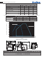
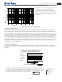
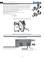
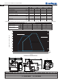
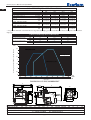
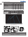
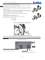
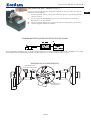
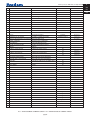
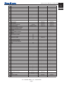
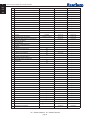
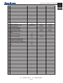
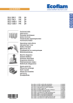
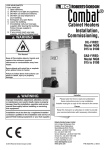
IT
EN
FR
ES
BRUCIATORI A GAS PROGRESSIVI
PROGRESSIVE GAS BURNERS
BRULEURS GAZ PROGRESSIVES
QUEMADOR DE GAS PROGRESIVOS
MAX GAS 70 PR
MAX GAS 105 PR
MAX GAS 120 PR
Low Nox
420010386502
30.11.2011
420010386502 Max Gas 70-105-120 PR
CARATTERISTICHE OPERATIVE
Modello : Max Gas 70-105-120 PR
Categoria gas - II 2H 3+B/P
Pressione massima*
Pressione minima*
Combustibile gas P.C.I.
Modello : Max Gas 70 PR
Portata gas
G20
360
12
8.570
G25
360
12
7.370
G31
360
30
22.260
G30
360
30
29.320
max.
min.
7,04 Nm3/h
2,52 Nm3/h
8,19 Nm3/h
2,93 Nm3/h
2,71 Nm3/h
0,97 Nm3/h
2,06 Nm3/h
0,74 Nm3/h
max.
min.
11,21 Nm3/h
4,67 Nm3/h
13,04 Nm3/h
4,68 Nm3/h
4,32 Nm3/h
1,55 Nm3/h
3,28 Nm3/h
1,17 Nm3/h
max.
min.
12,07 Nm3/h
4,67 Nm3/h
14,04 Nm3/h
4,68 Nm3/h
4,65 Nm3/h
1,55 Nm3/h
3,53 Nm3/h
1,17 Nm3/h
mbar
mbar
kcal/Nm3
Modello : Max Gas 105 PR
Portata gas
Modello : Max Gas 120 PR
Portata gas
* : Le pressioni minima e massima effettiva dipendono dalla rampa gas abbinata al bruciatore. I valori sono riportati nel manuale rampe gas.
CARATTERISTICHE TECNICHE
Potenza termica max.
mbar
Max Gas 70 PR
Max Gas 105 PR
Max Gas 120 PR
70
60.340
25
21.600
108
96.100
40
34.480
120
103.450
40
34.480
kW
kcal/h
kW
kcal/h
Potenza termica min.
Contropressione in camera di combustione
CURVE DI LAVORO
4
3,5
MAXGAS
GAS70
70PAB
PR
MAX
3
MAX GAS 120 PR
2,5
2
MAX GAS 105 PR
1,5
1
0,5
0
10
20
10
30
20
30
40
40
50
50
60
60
70
70
80
80
90
100
kcal/h
x 1000
100
90
110
120 kW
Potenza
DIMENSIONI D’INGOMBRO
A
B
D-D1
C
E
151
126
N
L
F
O
P
M
G
IT
MODELLO
MAX GAS 70 PR
MAX GAS 105 PR
MAX GAS 120 PR
A
B
C
303
317
317
155
169
169
148
148
148
D
D1
E
F
G
I
L
85
185 282
89
160 100/120 100/120
140 220 282
89
160 100/120 100/120
160 240 282
98
160 100/120 100/120
D = TESTA CORTA
D1= TESTA LUNGA
pag.2
I
M
N
O
P
M8
M8
M8
52
52
52
71
71
71
82
82
82
420010386502 Max Gas 70-105-120 PR
L’installazione deve essere fatta in conformità alle disposizioni locali.
4,0
d=0,8
(b)
Lunghezza camera di combustione
3,0
d=0,7
2,0
d=0,6
d=0,5
1,0
0,6
0,5
0,4
I bruciatori sono stati omologati in camere di
combustione secondo le norme EN 676.
Se le dimensioni della camera di combustione
della caldaia, nella quale deve essere installato il
bruciatore, è più piccola, consultare il costruttore
del bruciatore.
d=0,4
d=0,3
0,3
d=0,225
0,2
0,1
12
24
40
(a)
70 100
190
480
1200
2450
kW d = diametro camera di combustione
AVVIAMENTO DEL BRUCIATORE
CONTROLLI PRELIMINARI
Prima di avviare il bruciatore effettuare i seguenti controlli : - Tipo di gas e pressione di alimentazione - Valvole gas
chiuse. - La tenuta dei raccordi - Sfiato tubazione gas e controllo pressione entrata - Il cablaggio conforme allo schema e
fase e neutro rispettati - L’apertura del termostato caldaia ferma il bruciatore - La tenuta del focolare della caldaia per
evitare l’entrata di aria - La tenuta del raccordo camino-caldaia - Condizioni del camino ( stagno, non ostruito,.......). Se
tutte queste condizioni sono soddisfatte avviare il bruciatore. L’apparecchiatura di controllo avvia il motore per effettuare ilprelavaggio della camera di combustione. Durante questo periodo di prelavaggio (circa 30 secondi), l’apparecchiatura controlla che la pressione dell’aria sia corretta tramite il pressostato aria. Al termine, dà tensione al trasformatore e
apre le valvole del gas. La formazione della fiamma deve avvenire e stabilizzare entro 3 secondi, che é il tempo di sicurezza dell’apparecchiatura. Controllare visivamente la fiamma prima di inserire qualsiasi strumento di controllo nel camino. Regolare e controllare al contatore la portata di gas necessaria alla caldaia. Adeguare alla portata del gas la portata
dell’aria per una corretta combustione.
CONSIGLI IMPORTANTI
Tutti gli organi regolabili devono essere fissati dall’installatore dopo le regolazioni. Ad ogni regolazione controllate la
combustione al camino. I valori di CO2 devono essere circa 9,7(G20) 9,6(G25) 11,7(G30) 11,7(G31) ed il CO inferiore
a 75 ppm.
SISTEMA DI RILEVAZIONE FIAMMA
(LANDIS & STAEFA LGB 21/LGB 22
Termostato
Motore
Pressostato aria
Trasformatore
Valvola gas
Fiamma
≥ 30 s
3s
0,5 s
Segnale necessario in entrata
Segnale in uscita dell'apparecchiatura
CALCOLO DELLA PORTATA DI FUNZIONAMENTO DEL BRUCIATORE
Per calcolare la portata di funzionamento, in kW, del bruciatore, procedere nel modo seguente:
- Controllare al contatore la quantità di litri erogati e la durata, in secondi, della lettura, quindi
procedere al calcolo della portata secondo la seguente formula:
e x f = kW
s
pag.3
e = Litri di gas
s = Tempo in secondi
G20 = 34,02
G25 = 29,25
f G30 = 116
G31 = 88
IT
420010386502 Max Gas 70-105-120 PR
REGOLAZIONE PRESSOSTATO ARIA
2,7
1,5
1,8
2,1
3,0
0,4
1,2
Il pressostato aria deve essere regolato in modo che una insufficiente portata aria non faccia superare il valore di CO a 1% in volume. Dopo aver regolato la portata del gas e attenuto una combustione ottimale (CO2 = 9,5 ÷ 9,8% e CO inferiore a 75 ppm), bisogna regolare il pressostato
aria. Togliere il coperchio; durante il funzionamento del bruciatore coprire progressivamente
l’aspirazione dell’aria con un cartone in modo da ottenere un valore di CO2 = 10,8 (G 20 - G
25),13 (G 30 - G 31) e un CO inferiore a 5.000 ppm.
Regolare il pressostato dell’aria fino all’arresto del bruciatore. Togliere il cartone dall’aspirazione
dell’aria e fare ripartire il bruciatore. Rimettere quindi il coperchio.
2,4
0,6
0,9
A
B
REGOLAZIONE PRESSOSTATO GAS
45
25
30
35
50
Regolare il pressostato ad una pressione del 50% della pressione nominale
del gas utilizzato.
PRESSIONE NOMINALE : G 20 = 20 mbar
G 25 = 25 mbar
G 30 = 29 mbar
G 31 = 37 mbar
40
20
2,5
5
10
15
C
D
1
2
REGOLAZIONE TESTA DI COMBUSTIONE
0
IT
+
REGOLAZIONE DELLE ELETTROVALVOLE GAS
La portata gas di accensione viene accuratamente regolata in fase di collaudo ad 1/3 della portata massima (secondo normativa).
L’operazione di eventuale regolazione deve essere effettuata da personale specializzato ed autorizzato ECOFLAM.
MULTIBLOC MB-VEF...
fig.2
Massima Potenza
Agire sulla regolazione V per aumentare o diminuire
la portata gas alla massima potenza. (fig.2).
Minima Potenza
Agire sulla regolazione N per aumentare o diminuire
la portata gas alla minima potenza. (fig.2).
pag.4
420010386502 Max Gas 70-105-120 PR
SERVOCOMANDO ARIA ( SIEMENS SQN 75 )
Togliere il coperchio per accedere alle camme di regolazione. Lo spostamento delle
camme va effettuato con l’ausilio dell’apposita chiavetta (in dotazione), e di un giravite
a taglio. Descrizione :
I - Camma (CELESTE) di regolazione della posizione serranda allo spegnimento
(chiusura totale 0°).
II - Camma ( ARANCIONE) di regolazione posizione di apertura in accensione e 1°
fiamma (con giravite).
III - Camma ( ROSSA) di regolazione posizione di apertura in 2° fiamma
(potenza max).
IV - Camma non usata.
CONTROLLO SISTEMA DI RILEVAZIONE FIAMMA
A bruciatore spento inserire un microamperometro in corrente continua e scala 0÷50 o 0÷100 µA.
Con il bruciatore in funzione, e regolato correttamente, il valore letto dovrà essere stabile e mai inferiore a 3 µA.
POSIZIONE ELETTRODI
ELETTRODO DI
RIVELAZIONE
6
3
ELETTRODO DI
ACCENSIONE
30
18
pag.5
IT
IT
420010386502 Max Gas 70-105-120 PR
MONTAGGIO DEL BRUCIATORE
+
3
–
2
1
RIMOZIONE BOCCAGLIO
+
–
pag.6
420010386502 Max Gas 70-105-120 PR
MANUTENZIONE
CONTROLLO ANNUALE
Il controllo periodico del bruciatore (testa di combustione, elettrodi,ecc.) deve essere effettuato da personale
autorizzato una o due volte all’anno a secondo dell’utilizzo.
Prima di procedere al controllo per la manutenzione del bruciatore è consigliabile verificare lo stato generale
del bruciatore e seguire le seguenti operazioni :
- Togliere tensione al bruciatore (togliere la spina)
- Chiudere il rubinetto di intercettazione gas
- Togliere il coperchio del bruciatore, pulire la ventola e l’aspirazione dell’aria
- Pulire la testa di combustione e controllare la posizione degli elettrodi
- Rimontare i pezzi
- Verificare la tenuta dei raccordi gas
- Verificare il camino
- Far ripartire il bruciatore
- Controllare i parametri della combustione
(CO2 = 9,7(G 20); 9,6(G 25); 11,7(G 30); 11,7(G 31),(CO = inferiore a 75 ppm)
PRIMA DI OGNI INTERVENTO CONTROLLARE :
- Che ci sia corrente elettrica nell’impianto e il bruciatore collegato.
- Che la pressione del gas sia corretta e il rubinetto di intercettazione del gas aperto.
- Che i sistemi di controllo siano regolarmente collegati.
Se tutte queste condizioni sono soddisfatte , far partire il bruciatore premendo il pulsante di sblocco.
Controllare il ciclo del bruciatore.
IL BRUCIATORE NON SI AVVIA :
- Controllare l’interruttore, i termostati, il motore, pressione gas.
IL BRUCIATORE EFFETTUA LA PREVENTILAZIONE E AL TERMINE DEL CICLO VA IN
BLOCCO :
- Controllare la pressione dell’aria e la ventola.
- Controllare il pressostato aria.
IL BRUCIATORE EFFETTUA LA PREVENTILAZIONE E NON ACCENDE :
- Verificare il montaggio e la posizione degli elettrodi.
- Verificare il cavo di accensione.
- Verificare il trasformatore di accensione.
- Verificare l’apparecchiatura di sicurezza.
IL BRUCIATORE SI ACCENDE E DOPO IL TEMPO DI SICUREZZA VA IN BLOCCO :
- Controllare fase e neutro che siano collegati correttamente.
- Controllare l’elettrovalvole del gas.
- Controllare la posizione dell’elettrodo di rivelazione e la sua connessione.
- Controllare l’elettrodo di rivelazione.
- Controllare l’apparecchiatura di sicurezza.
IL BRUCIATORE SI ACCENDE E DOPO QUALCHE MINUTO DI FUNZIONAMENTO VA IN BLOCCO :
- Controllare il regolatore di pressione e il filtro gas.
- Controllare la pressione del gas con un manometro.
- Controllare il valore di rivelazione (min 3 µA).
pag.7
IT
420010386502 Max Gas 70-105-120 PR
EN
OPERATING FEATURES
Models : Max Gas 70-105-120 PR
Gas family - II 2H 3+B/P
Max. gas pressure*
Min. gas pressure*
Fuel L.C.V.
Model : Max Gas 70 PR
Gas flow rate
G20
360
12
8.570
G25
360
12
7.370
G31
360
30
22.260
G30
360
30
29.320
max.
min.
7,04 Nm3/h
2,52 Nm3/h
8,19 Nm3/h
2,93 Nm3/h
2,71 Nm3/h
0,97 Nm3/h
2,06 Nm3/h
0,74 Nm3/h
max.
min.
11,21 Nm3/h
4,67 Nm3/h
13,04 Nm3/h
4,68 Nm3/h
4,32 Nm3/h
1,55 Nm3/h
3,28 Nm3/h
1,17 Nm3/h
max.
min.
12,07 Nm3/h
4,67 Nm3/h
14,04 Nm3/h
4,68 Nm3/h
4,65 Nm3/h
1,55 Nm3/h
3,53 Nm3/h
1,17 Nm3/h
mbar
mbar
kcal/Nm3
Model : Max Gas 105 PR
Gas flow rate
Model : Max Gas 120 PR
Gas flow rate
* : Minimum/maximum gas inlet pressures depend by the gas train matched to the burner. The values are written on the gas trains manual.
TECHNICAL DATA
Termal power max.
Max Gas 120 PR
108
96.100
40
34.480
120
103.450
40
34.480
WORKING FIELDS
4
3,5
Backpressure in comb. chamber
Max Gas 105 PR
70
60.340
25
21.600
kW
kcal/h
kW
kcal/h
Termal power min.
mbar
Max Gas 70 PR
MAXGAS
GAS70
70PAB
PR
MAX
3
MAX GAS 120 PR
2,5
2
MAX GAS 105 PR
1,5
1
0,5
0
10
20
10
30
20
30
40
40
50
50
60
60
70
70
80
80
90
100
kcal/h
x 1000
100
90
110
120 kW
Output
OVERALL DIMENSIONS
A
B
D-D1
C
E
151
126
N
L
F
O
P
G
M
MODELS
A
MAX GAS 70 P AB 303
MAX GAS 105 P AB 317
MAX GAS 120 P AB 317
B
C
155
169
169
148
148
148
D
D1
E
85
185 282
140 220 282
160 240 282
D = SHORT HEAD
pag.8
F
G
I
L
89
160 100/120 100/120
89
160 100/120 100/120
98
160 100/120 100/120
D1= LONG HEAD
I
M
N
O
P
M8
M8
M8
52
52
52
71
71
71
82
82
82
420010386502 Max Gas 70-105-120 PR
Installation must be carried out in compliance with the local provisions
(b)
Longueur chambre de combustion
4,0
d=0,7
2,0
d=0,6
d=0,5
1,0
0,6
0,5
0,4
d=0,4
d=0,3
0,3
0,2
The burners have been certified in combustion
chambers according to EN 676 standards.
Consult the burner manufacturer if the combustion chamber of the boiler in which the
burner is to be installed has smaller dimensions.
d=0,8
3,0
d=0,225
0,1
12
(a)
24
40
70 100
190
480
1200
2450
kW d = diamètre chambre de combustion
STARTING-UP THE BURNER
PRELIMINARY CHECKS
Before starting up the boiler check the following: - gas type and feed pressure; - gas valves closed; - the seals in the pipe
fittings; - gas pipe breather and input pressure; - that the cable complies with the diagram and the phase and neutral
wires correspond; - that the burner shuts down when the boiler thermostat opens; - the seal of the boiler furnace which
prevents air from entering; - the seal on the flue-boiler pipe fitting; - the condition of the flue (sealed, free from blockage, etc ). If all these conditions are present, start the burner. The control device starts the motor to carry out prewashing
of the combustion chamber. During this prewash period (about 30 seconds) the device checks that air pressure is correct
via the air pressure switch. At the end, it supplies power to the transformer and opens the gas valves. The flame must be
lit and stabilize within 3 seconds, which is the device's safety time limit. Check to ensure the flame is lit before placing
any control instrument in the flue. Adjust and check the gas flow necessary for the boiler at the meter. Adjust the air
flow according to the gas flow to obtain correct combustion.
IMPORTANT ADVICE
All adjustable parts must be fixed by the installer after making adjustments. Check flue combustion after each adjustiment. The CO2 values must be approx. 9.7 (G20) 9.6 (G25) 11.7 (G30) 11.7 (G31) axld the CO must be less than 75
ppm.
(LANDIS & STAEFA LGB 21/LGB 22 UP CYCLE
Thermostat
motor
Air pressure switch
Transformer
Gas valve
Flame
≥ 30 s
3s
0,5 s
Necessary input signal
output signal of the device
CALCULATION OF WORKING OUTPUT OF THE BURNER
To calculate the burner’s working output, in kW, proceed as follows:
e = Litres of gas
- Check at the meter the quantity of supplied litres and the duration, in seconds, of the
reading, then calculate the burner’s output through the following formula:
s = Time in seconds
e x f = kW
s
pag.9
f
G20 = 34,02
G25 = 29,25
G30 = 116
G31 = 88
EN
420010386502 Max Gas 70-105-120 PR
ADJUSTING THE AIR PRESSURE SWITCH
2,7
1,5
1,8
2,1
3,0
0,4
1,2
The air pressure switch must be adjusted so that an insufficient air flow does not allow
the CO value to exceed 1% in volume. After having adjusted the gas flow and obtained
optimum combustion (CO2 = 9.5 to 9.8% and a CO value of less than 75 ppm), the air
pressure switch must be adjusted. Remove the cover with the burner operating, cover
the air intake progressively with a piece of cardboard to obtain a value of CO2 = 10.8
(G20-G25)> 13 (G30-G31) and a CO value of less than 5,000 ppm. Adjust the air
pressure switch until the burner shuts down. Remove the cardboard from the air intake
and start up the burner again. Replace the cover.
2,4
0,6
0,9
A
B
45
40
25
30
35
50
5
20
2,5
ADJUSTING THE GAS PRESSURE SWITCH
10
Adjust the pressure switch to 50% of the rated pressure of the gas used.
RARED PRESSURE:
G 20 = 20 mbar
G 25 = 25 mbar
G 30 = 29 mbar
G 31 = 37 mbar
15
C
D
1
2
SETTING THE FIRING HEAD
0
EN
+
ADJUSTMENT OF GAS SOLENOID VALVES
The ignition flow rate is carefully adjusted. during test phase to 1/3 of the maximum flow rate (according to specifications).
Operations for eventual further adjustment must be carried out by skilled personnel authorized by ECOFLAM
BRUCIATORI.
MULTIBLOC MB-VEF...
fig.2
Setting at full-load
Adjust gas/air ratio with screw V (fig.2).
- More CO2 in direction of higher scale values.
- Less CO2 in the direction of lower scale value.
Setting at low-load
Adjust gas flow with screw N (fig.2).
- More CO2 in direction of higher scale values.
- Less CO2 in the direction of lower scale value.
pag.10
420010386502 Max Gas 70-105-120 PR
AIR SERVOMOTOR ( SIEMENS SQN 75 )
Remove cover to enter the adjusting cams. Adjust cams through the suitable key (on
issue) and a screwdriver.
I - Adjusting cam (BLUE) for air damper position on burner’s shutdown
(total close 0°).
II - Adjusting cam (ORANGE) for opening position in ignition and Low Flame
(by the screwdriver).
III - Adjusting cam (RED) for opening position in High Flame (max. output).
IV - Not used cam.
FLAME DETECTION SYSTEM CHECK
With the burner switched off, connect a DC microammeter with a 0÷50 or 0÷100 µA dial. When the burner is running, and is properly adjusted, the value read must be steady and never be smaller than 3 µA(Landis).
POSITION OF ELECTRODES
IONIZATION
PROBE
6
3
30
18
pag.11
IGNITION
ELECTRODE
EN
420010386502 Max Gas 70-105-120 PR
EN
MOUNTING TO THE BOILER
+
3
–
2
1
TUBE DISASSEMBLY
+
–
pag.12
420010386502 Max Gas 70-105-120 PR
MAINTENANCE
YEARLY INSPECTION
Periodic inspection of the burner (combustion head, electrodes, etc.) must be carried out by authorised personnel once or twice a year, depending of use. Before carrying out maintenance inspection on the burner, it
is advisable to check its general condition and carry out the following operations:
- Disconnect the burner from the power supply (remove the plug).
- Close the gas cock.
- Remove the burner cover, clean the fan and air intake.
- Clean the combustion head and check the position of the electrodes.
- Re-assemble the parts.
- Check the seal on the gas pipe fittings.
- Check the flue.
- Restart the burner.
- Check the combustion parameters (CO2 = 9.5 to 9.8),(CO = less than 75 ppm)
BEFORE EACH INTERVENTION CHECK;
- That the system is supplied with power and the burner connected.
- That the gas pressure is correct and the gas cock open.
- That the control systems are correctly connected.
If all these conditions are present, start the burner by pressing the release button. Check the burner cycle.
THE BURNER WILL NOT START;
- Check the switch, thermostats, motor, gas pressure.
THE BURNER PREVENTILATES AND LOCKS AT THE END OF THE CYCLE:
- Check the air pressure and fan.
- Check the air pressure switch.
THE BURNER PREVENTILATES AND WILL NOT IGNITE:
- Check the assembly and position of electrodes.
- Check the ignition cable.
- Check the ignition transformer.
- Check the safety devices.
THE BURNER STARTS UP AND LOCKS AFTER THE SAFETY TIME LIMIT:
- Check that the phase and neutral wires are correctly connected.
- Check the gas electrovalves.
- Check the position of the detection electrode and its connection.
- Check the detection electrode.
- Check the safety devices.
THE BURNER STARTS UP AND LOCKS AFTER RUNNING FOR A FEW MINUTES.
- Check the pressure regulator and the gas filter.
- Check the gas pressure with an ammeter.
- Check the detection value (min 3 µA Landis).
pag.13
EN
420010386502 Max Gas 70-105-120 PR
CARACTERISTIQUES OPERATIONNELLES
Modele : Max Gas 70-105-120 PR
Famille du gaz
Pression max. *
Pression min. *
Combustibile gas P.C.I.
Modele : Max Gas 70 PR
Débit gaz
G20
360
12
8.570
G25
360
12
7.370
G31
360
30
22.260
G30
360
30
29.320
max.
min.
7,04 Nm3/h
2,52 Nm3/h
8,19 Nm3/h
2,93 Nm3/h
2,71 Nm3/h
0,97 Nm3/h
2,06 Nm3/h
0,74 Nm3/h
max.
min.
11,21 Nm3/h
4,67 Nm3/h
13,04 Nm3/h
4,68 Nm3/h
4,32 Nm3/h
1,55 Nm3/h
3,28 Nm3/h
1,17 Nm3/h
max.
min.
12,07 Nm3/h
4,67 Nm3/h
14,04 Nm3/h
4,68 Nm3/h
4,65 Nm3/h
1,55 Nm3/h
3,53 Nm3/h
1,17 Nm3/h
mbar
mbar
kcal/Nm3
Modele : Max Gas 105 PR
Débit gaz
Modele : Max Gas 120 PR
Débit gaz
* : Les pressions minimum et maximum effectives dépendent de la rampe gaz associée au brûleur. Les valeurs sont reportées dans le manuel
rampes gaz.
CARACTERISTIQUES DU BRULEUR
Puissance thermique max.
mbar
Max Gas 70 PR
Max Gas 105 PR
Max Gas 120 PR
70
60.340
25
21.600
108
96.100
40
34.480
120
103.450
40
34.480
kW
kcal/h
kW
kcal/h
Puissance thermique min.
Contrepression en chambre de combustion
COURBE DE TRAVAIL
4
3,5
MAXGAS
GAS70
70PAB
PR
MAX
3
MAX GAS 120 PR
2,5
2
MAX GAS 105 PR
1,5
1
0,5
0
10
20
10
30
20
30
40
40
50
50
60
60
70
Puissance
70
80
80
90
kcal/h
x 1000
100
90
100
110
120 kW
DIMENSIONS D'ENCOMBREMENT
A
B
D-D1
C
E
151
126
N
L
F
O
P
M
G
FR
MODELE
MAX GAS 70 PR
MAX GAS 105 PR
MAX GAS 120 PR
A
B
C
303
317
317
155
169
169
148
148
148
D
D1
E
F
G
I
L
85
185 282
89
160 100/120 100/120
140 220 282
89
160 100/120 100/120
160 240 282
98
160 100/120 100/120
D = TETE COURTE
D1= TETE LONGUE
pag.14
I
M
N
O
P
M8
M8
M8
52
52
52
71
71
71
82
82
82
420010386502 Max Gas 70-105-120 PR
L’INSTALLATION DOIT ETRE FAIT SELOM LES DISPOSITIONS LOCALIES.
Lunguieur chambre de combustion
4,0
d=0,8
3,0
d=0,7
2,0
d=0,6
d=0,5
1,0
0,6
0,5
0,4
Les bruleurs sont ete homologues dans la chambre de combustion selon les normes EN 676. Si
le dimensions de la chambre de combustion de la
cHaudiere, dans la quelle il faut installer le bruleur,est plus petite i l faut consulter le constructeur du bruleur.
d=0,4
d=0,3
0,3
d=0,225
(b)
0,2
0,1
12
24
40
(a)
70 100
190
480
1200
2450
kW d = diametre cambre di combustion
DEMARRAGE DU BRULEUR
CONTROLES PRELIMINAIRES
Avant de faire démarrer le brûleur, effectuer les contrôles suivants:
• Type de gaz et pression d’alimentation.• Soupapes gaz fermées.• Etanchéité des raccords.• Purge canalisation gaz et
contrôle pression à l’entrée. • Que le câblage soit conforme au schéma et que la phase et le neutre soient respectés.• Que
l’ouverture du thermostat chaudière arrête le brûleur.• L’étanchéité du foyer de la chaudière pour éviter l’entrée d’air. •
L’étanchéité du raccord cheminée/ chaudière.• Les conditions de la cheminée (étanche, non bouchée, ...). Si toutes ces
conditions sont remplies, faire démarrer le brûleur.
Le boîtier de contrôle fait démarrer le moteur pour effectuer le prélavage de la chambre de combustion. Durant ce
temps de prélavage (environ 30 secondes), le boîtier contrôle que la pression de l’air soit correcte à l’aide du pressostat
air. A la fin de cette opération, il donne du courant au transformateur et ouvre les soupapes gaz. La flamme doit se former et se stabiliser en 3 secondes, qui correspond au temps de sécurité de l’appareil. Contrôler la flamme de façon
visuelle avant d’installer un instrument de contrôle quelconque dans la cheminée.Régler et contrôler le débit de gaz
nécessaire à la chaudière sur le compteur. Adapter le débit d’air au débit du gaz pour une combustion correcte.
CONSEILS IMPORTANTS: Tous les organes réglables doivent être fixés par l’installateur après les réglages.
Contrôler la combustion dans la cheminée à chaque réglage. Les valeurs de CO2 doivent être d’environ 9,7 (G20) - 9,6
(G25) - 11,7 (G30) - 11,7 (G31) et le CO doit être inférieur à 75 p.p.m.
SYSTEME DETECTION DE FLAMME
(LANDIS & STAEFA LGB 21/LGB 22
Thermostat
Moteur
Pressostat air
Transformateur
Soupape gaz
Flamme
≥ 30 s
3s
0,5 s
Signal nécessaire à lʼentrée
Signal à la sortie de lʼappareil
CALCUL DU DEBIT DE FONCTIONNEMENT DU BRULEUR
Pour calculer le débit de fonctionnement, en kW, du brûleur, procéder de la manière suivante: - Vérifier au compteur la quantité de litres débités, ainsi
e x f = kW
que la durée de la lecture, ensuite procéder au calcul du débit
s
par la formule suivante:
pag.15
e = Litres de gaz
s = Temps en secondes
G20 = 34,02
G25 = 29,25
f G30 = 116
G31 = 88
FR
420010386502 Max Gas 70-105-120 PR
REGLAGE PRESSOSTAT AIR
2,7
1,5
1,8
2,1
3,0
1,2
0,4
0,6
0,9
A
B
45
40
25
30
35
50
Le dispositif de surveillance d'air doit être réglé de telle manière qu'il interviene en cas
d'insuffisance d'air avant que la teneur en CO des gaz de combustion ne dépasse 1% en
volume. Après le réglage du débit gaz et
obtention d’une bonne hygiène de combustion (CO2 = 9,5÷9,8 % et CO inférieur à 75
ppm) il faut régler le pressostat d'air. Enlever le couvercle du pressostat. Pendant la marche normale du brûleur, couvrir l'aspiration d'air du brûleur à l'aide d'un morceau de
carton, progressivement de maniére à obtenir une valeur de CO2 = 10,6 et le CO inférieur à 10.000 ppm. Tourner progressivement le réglage du pressostat air jusqu'à l'arrêt
du brûleur. Enlever le morceau de carton de l'aspiration d'air et faire redémarrer le brûleur. Remettre le couvercle.
2,4
5
20
2,5
REGLAGE PRESSOSTAT GAZ
10
Enlever le couvercle du pressostat. Pendant le fonctionnement du brûleur, mesurer la pression sur le raccord du pressostat et fermer lentement la vanne d’arrêt gaz jusqu’ à ce que la
pression mesurée tombe de 50%. Serrer le bouton de réglage jusqu'à l'arrêt du brûleur.
Réouvrir la vanne d’arrêt. Remettre le couvercle.
G 20 = 20 mbar
G 25 = 25 mbar
G 30 = 29 mbar
G 31 = 37 mbar
15
C
D
1
2
REGLAGE TETE DE COMBUSTION
0
FR
+
REGULATION DES ELECTROVANNES GAZ
Le débit gaz d'allumage est soigneusement réglé pendant les essais en usine, à une valeur equivalente à 1/3 de la portée
maximale (suivant la normative). L'opération eventuelle de régulation doit être effectuée par un technicien
spécialisé et agrée par ECOFLAM BRUCIATORI.
MULTIBLOC MB-VEF...
fig.2
Puissance thermique max.
Agire sulla regolazione V per aumentare o diminuire
la portata gas alla massima potenza. (fig.2).
Puissance thermique min.
Agire sulla regolazione N per aumentare o diminuire
la portata gas alla minima potenza. (fig.2).
pag.16
420010386502 Max Gas 70-105-120 PR
SERVOMOTEUR AIR ( SIEMENS SQN 75 )
Enlever le couvercle pour accéder aux cames. Réguler les cames à l’aide de la clé appropriée(en dotation) et du tournevis.
I - Came de régulation (BLEUE) pour la position du clapet d’air à extinction du
brûleur
(fermer total 0°).
II - Came de régulation (ORANGE) pour l’ouverture en allumage et 1e Allure
(avec le tournevis).
III - Came de régulation (ROUGE) pour la position d’ouverture en 2e Allure
(puissance max.).
IV - Came de régulation libre (non utilisé).
CONTROLE SYSTEME DETECTION DE FLAMME
Avec le brûleur éteint, brancher un microamperomètre à courante continue et échelle 0÷50 ou 0÷100 µA.
Avec le brûleur en fonction, et dûment régulé, la valeur lue doit être stable et ne jamais être inférieure à 3 µA.
POSITIONNEMENT DES ELECTRODES
IONIZATION
PROBE
6
3
30
18
pag.17
IGNITION
ELECTRODE
FR
420010386502 Max Gas 70-105-120 PR
MONTAGE DU BRULEUR
FR
+
3
–
2
1
DEMONTAGE DU GUEULARD
+
–
pag.18
420010386502 Max Gas 70-105-120 PR
MAINTENANCE
CONTROLE ANNUEL:
Le contrôle périodique du brûleur (tête de combustion, électrodes etc.) doit être fait, par des techniciens autorisés, une ou deux fois par an, suivant les conditions d’utilisation. Avant de procéder avec les opérations
d’entretien, il serait souhaitable d’effectuer une vérification de l’état général du brûleur de la manière suivante:
- Débrancher le brûleur du réseau.
- Fermer le robinet du gaz.
- Enlever le couvercle du brûleur et nettoyer le ventilateur ainsi que le conduit d’aspiration d’air.
- Nettoyer la tête de combustion et vérifier la position des électrodes.
- Remonter le tout.
- Vérifier l’étanchéité des raccords gaz.
- Contrôler la cheminée.
- Redémarrer le brûleur et en contrôler les paramètres de combustion
(CO2 = 9,7% (G 20); 11,7% (G 30); 11,7% (G 31); CO inférieur a 75 ppm).
Avant de chaque intervention contrôler:
Qu’il y soit courante électrique dans l’installation et que le brûleur soit branché.
- Que la pression du gaz soit celle correcte et que le robinet du gaz soit ouvert.
- Que les dispositifs de contrôle soient dûment branchés.
- Lorsque toutes ces conditions sont satisfaites, démarrer le brûleur en appuyant sur le bouton du réarmement
de la mise en sécurité, et en vérifier la séquence d’allumage.
BREVE GUIDE AU DEPANNAGE:
- Le brûleur ne démarre pas:
contrôler l’interrupteur d’allumage, les thermostats, le moteur, la pression du gaz et le dispositif du contrôle
d’étanchéité (s’il y en a).
- Le brûleur effectue le prébalayage mais se met en sécurité à la fin du cycle:
contrôler la pression de l’air, le ventilateur ainsi que le pressostat air.
- Le brûleur effectue le prébalayage mais ne s’allume pas:
vérifier le montage et la position des électrodes, le câble d’allumage, le transformateur d’allumage, le coffret de
sécurité et les électrovannes du gaz.
- Le brûleur s’allume mais se met en sécurité après l’écoulement du temps de sécurité:
contrôler que la phase et le neutre soient dûment connectés; contrôler position et connexion de la sonde d'ionisation; vérifier le coffret de sécurité.
- Le brûleur s’allume normalement mais se met en sécurité après quelques minutes de fonctionnement:
contrôler le régulateur de pression et le filtre gaz; contrôler la pression du gaz; contrôler la valeur de détection
(3 µA min.); contrôler les valeurs de la combustion.
pag.19
FR
420010386502 Max Gas 70-105-120 PR
CARACTERÍSTICAS OPERATIVAS
Modelo : Max Gas 70-105-120 PR
Presión gas máx.*
Presión gas mín.*
Combustible gas P.C.I.
Modelo : Max Gas 70 PR
Caudal gas
Familia de gas
G25
G31
360
360
12
30
7.370
22.260
G20
360
12
8.570
mbar
mbar
kcal/Nm3
Modelo : Max Gas 105 PR
Caudal gas
G30
360
30
29.320
max.
min.
7,04 Nm3/h
2,52 Nm3/h
8,19 Nm3/h
2,93 Nm3/h
2,71 Nm3/h
0,97 Nm3/h
2,06 Nm3/h
0,74 Nm3/h
max.
min.
11,21 Nm3/h
4,67 Nm3/h
13,04 Nm3/h
4,68 Nm3/h
4,32 Nm3/h
1,55 Nm3/h
3,28 Nm3/h
1,17 Nm3/h
Modelo : Max Gas 120 PR
Caudal gas
max.
12,07 Nm3/h 14,04 Nm3/h 4,65 Nm3/h
3,53 Nm3/h
min.
4,67 Nm3/h
4,68 Nm3/h
1,55 Nm3/h
1,17 Nm3/h
* : Las presiones mínima y máxima efetivas dependen del circuito del gas montado en el quemador. Los valores se encuentran en el
manual del circuito del gas.
CARACTERISTICAS TECNICAS
Potencia térmica máx .
mbar
Max Gas 70 PR
Max Gas 105 PR
Max Gas 120 PR
70
60.340
25
21.600
108
96.100
40
34.480
120
103.450
40
34.480
kW
kcal/h
kW
kcal/h
Potencia térmica míx .
CAMPO DE TRABAJO
4
3,5
Contropresión en cámara de combustión
MAXGAS
GAS70
70PAB
PR
MAX
3
MAX GAS 120 PR
2,5
2
MAX GAS 105 PR
1,5
1
0,5
0
10
20
10
30
20
30
40
40
50
50
60
60
70
70
Potencia
80
80
90
kcal/h
x 1000
100
90
100
110
120 kW
DIMENSIONES TOTALES
A
B
D-D1
C
E
151
126
N
L
F
O
P
M
G
ES
MODELO
MAX GAS 70 PR
MAX GAS 105 PR
MAX GAS 120 PR
A
B
C
303
317
317
155
169
169
148
148
148
D
D1
E
F
G
I
L
85
185 282
89
160 100/120 100/120
140 220 282
89
160 100/120 100/120
160 240 282
98
160 100/120 100/120
D = CABEZA CORTA
D1= CABEZA LARGA
pag.20
I
M
N
O
P
M8
M8
M8
52
52
52
71
71
71
82
82
82
420010386502 Max Gas 70-105-120 PR
La instalación debe ser efectuada en conformidad a las disposiciones locales.
(b)
Largueza
decamera
la cámara
de combustión
Lunghezza
di combustione
4,0
Los quemadores han sido homologados en cámaras de combustión según las normas EN 676. Si
las medidas de la cámara de combustión de la
caldera, en la cual debe ser instalado el quemador, son más pequeñas, consultar al fabricante
del quemador.
d=0,8
3,0
d=0,7
2,0
d=0,6
d=0,5
1,0
0,6
0,5
0,4
d=0,4
d=0,3
0,3
d=0,225
0,2
0,1
12
24
40
(a)
70 100
190
480
1200
2450
di combustione
kW d = diametro
Diámetrocamera
de la cámara
de combustión
PUESTA EN MARCHA DEL QUEMADOR
CONTROLES PRELIMINARES
Antes de poner en marcha el quemador, efectuar los siguientes controles:
• Tipo de gas y presión de alimentación. • Válvulas del gas cerradas. • Estanqueidad de las conexiones.• Purgar la tubería
del gas y control de la presión en ingreso. • Que el cableado sea conforme al esquema, con respeto de la fase y neutro.•
Que el quemador se pare cuando el termostato caldera se abre. • La estanqueidad del hogar para evitar el ingreso de aire.
• La estanqueidad de la conexión caldera-chimenea. • La condición de la chimenea (estanco, non obstruido...). Al cumplir de todas estas condiciones poner en marcha el quemador. El equipo de control arranca el quemador para efectuar el
prebarrido de la cámara de combustión. Durante este periodo de prebarrido (cerca de los 30 segundos) el equipo comprueba que la presión del aire sea correcta por medio del presostato del aire. Al termino alimenta el transformador y abre
las válvulas del gas. La formación de la llama tiene que efectuarse y estabilizarse dentro de los 3 secundos, que es el tiempo de seguridad del equipo. Averiguar a vista la presencia de la llama antes de introducir cualquiera instrumentación de
control. Regular y comprobar el caudal del gas necesario a la caldera por medio del contador.
Adecuar el caudal del aire al caudal del gas para obtener una combustión correcta.
ADVERTENCIAS IMPORTANTES
Todos los equipos regulables tienen que ser fijados por el instalador después de cada regulación. Por cada regulación
comprobar la combustión a la chimenea. Los valores de CO2 deben ser cerca de 9,7 (G20) 9,6 (G25) 11,7 (G30)
11,7(G31) y el CO inferior a los 75ppm.
LANDIS & STAEFA LGB 21/LGB 22
Termóstato
Motor
Presóstato aire
Transformador
Gas válvula
Llama
3s
≥ 30 s
0,5 s
Signal necesario en ingreso
Signal a la salida de equipo
CALCULO DE LA POTENCIA DE FUNCIONAMIENTO DEL QUEMADOR
Para calcular la potencia de funcionamiento, en kW, del quemador, proceder de la manera
siguiente: Comprobar al contador la cantidad de litros suministrados y la duración, en segundos, de la lectura, luego proceder al calculo de la potencia con la
e x f = kW
formula siguiente:
s
pag.21
e = Litri di gas
s = Tempo in secondi
G20 = 34,02
G25 = 29,25
f G30 = 116
G31 = 88
ES
420010386502 Max Gas 70-105-120 PR
REGULACIÓN DEL PRESÓSTATO AIRE
2,7
1,5
1,8
2,1
3,0
0,4
1,2
El presóstato aire tiene que ser regulado de modo que un caudal de aire insuficiente no
le permita de superar el valor de CO a 1% en volumen.
Después de haber regulado el caudal del gas y haber obtenido una combustión optimal
(CO2 = 9,5÷9,8% y CO inferior a 75 ppm), se necesita regular el presóstato del aire de
la siguiente manera:
- Remover la tapa del presóstato; durante la marcha del quemador, obstruir progresivamente la toma del aire con un tarjetón, de manera a obtener un valor de CO2 = 10,8
(G20 - G25) 13 (G30 - G31) y un CO inferior a 5.000 ppm.
- Regular el presóstato del aire hasta al apagado del quemador.
- Remover el tarjetón de la toma del aire y reponer en marcha el quemador.
2,4
0,6
0,9
A
B
- Remontar la tapa.
45
40
25
30
35
50
REGULACIÓN DEL PRESÓSTATO GAS
5
20
2,5
- Regular el presóstato a una presión del 50% de la presión nominal del gas
utilizado. Presión Nominal: G 20 = 20 mbar
G 25 = 25 mbar
G 30 = 29 mbar
G 31 = 37 mbar
10
15
C
D
1
2
REGULACIÓN CABEZA DE COMBUSTION
0
ES
+
REGULACIÓN DE LA ELECTROVALVULAS GAS
El caudal de encendido del gas ya está cuidadosamente regulada durante el ensaye, a 1/3 del caudal máximo (según las normas).
Una operación eventual de regulación debe ser efectuada por un técnico especializado y autorizado por ECOFLAM
BRUCIATORI.
MULTIBLOC MB-VEF...
fig.2
Potencia térmica máx.
Agire sulla regolazione V per aumentare o diminuire
la portata gas alla massima potenza. (fig.2).
Potencia térmica min.
Agire sulla regolazione N per aumentare o diminuire
la portata gas alla minima potenza. (fig.2).
pag.22
420010386502 Max Gas 70-105-120 PR
SERVOMOTOR AIRE ( SIEMENS SQN 75 )
Sacar la tapa para acceder a las levas de regulación. Regular las levas por medio de su llave de
suministro y un destornillador.
I - Leva de regulación (AZUL) para la posición del cierre del aire a la parada del quemador
(chiusura totale 0°).
II - Leva de regulación (ANARANJADA) para la posición de abertura en encendido y
Baja Llama (con el destornillador).
III - Leva de regulación (ROJA) para la posición de abertura en Alta Llama (potencia máx.)
IV - Came de régulation libre (non utilisé).
COMPROBACIÓN EQUIPO DE DETECCIÓN DE LLAMA
Con el quemador apagado, conectar un microamperómetro en corriente continua y escala 0÷50 o 0÷100 µA. Con el quemador funcionante y debidamente regulado, el valor leído debe ser estable y nunca inferior a 3 µA.
POSICIÓN DE LOS ELECTRODOS
ELECTRODO DE
CONTROL DE LLAMA
6
3
ELECTRODO DE
ENCENDIDO
30
18
pag.23
ES
420010386502 Max Gas 70-105-120 PR
INSTALACION EN LA CAMARA DE COMBUSTION
ES
+
3
–
2
1
DESMONTAJE DEL TUBO DE LLAMA
+
–
pag.24
420010386502 Max Gas 70-105-120 PR
MANTENIMIENTO
CONTROL ANUAL:
El control periódico del quemador (cabeza de combustión, electrodos etc.) tiene que ser efectuado por técnicos autorizados una o dos veces cada año, según la utilización del quemador. Antes de proceder con las operaciones de mantenimiento, es aconsejable comprobar el estado general del quemador actuando de la manera
siguiente:
- Desconectar la clavija del quemador de la red.
- Cerrar la válvula de cierre del gas.
- Sacar la tapa del quemador y limpiar ventilador y conducto de aspiración del aire.
- Limpiar la cabeza de combustión y comprobar la posición de los electrodos.
- Remontar el todo.
- Comprobar la estanqueidad de las uniones del gas.
- Comprobar la chimenea.
- Arrancar el quemador y comprobar los parámetros de combustión
(CO2 = 9,7% (G 20); 11,7% (G 30); 11,7% (G 31); CO inferior a 75 ppm).
Antes de cada intervención comprobar:
- Que hay corriente en la instalación y que el quemador sea conectado.
- Que la presión del gas sea la correcta y la válvula de cierre esté abierta.
- Que los equipos de control estén debidamente conectados.
- Cuando todas estas condiciones se cumplen, arrancar el quemador presionando el botón de bloqueo
y comprobar la secuencia de encendido.
Breve guía de averías:
- El quemador no arranca:
comprobar el interruptor de arranque, los termostatos, el motor, la presión del gas, el equipo de control de
estanqueidad (si lo hay).
- El quemador efectúa el prebarrido pero se pone en seguridad al final del ciclo:
comprobar la presión del aire, el ventilador y el presostato del aire.
- El quemador efectúa el prebarrido pero no se enciende:
comprobar el montaje y la posición de los electrodos, el cable de encendido, el transformador de encendido,
el equipo de control llama y las electroválvulas del gas.
- El quemador se enciende pero se pone en seguridad al cumplir del tiempo de seguridad:
comprobar que fase y neutro sean conectados correctamente; comprobar posición y conexión de la sonda de
ionización; comprobar el equipo de control de llama.
- El quemador se enciende normalmente pero se pone en seguridad después unos minutos de
funcionamiento:
comprobar el regulador de presión y el filtro del gas; controlar la presión del gas; controlar el valor de ionización (3 µA); comprobar los valores de la combustión.
pag.25
ES
COMUNICARE A TERZI IL CONTENUTO DEL PRESENTE.
A TERMINE DI LEGGE E' VIETATO RIPRODURRE O
PROPRIETA' RISERVATA DELLA DITTA ECOFLAM S.p.A.
E
D
C
B
IND.MOD.
SOST.DA
00
DATA-FIRMA
PARA INSTALACION EN CALDERAS
NON ECOFLAM VER AL ESQUEMA
AL LADO.
CUIDADO !
POUR INSTALLATION SUR
CHAUDIERES NON FABRIQUER PAR
ECOFLAM, SUNRE LE SCHEMA A COTE.
ATTENTION
FOR INSTALLATION ON BOILES
NOT MANUFACTURES BY ECOFLAM
FOLLOW THE DIAGRAM SHOWN.
WARNING !
03
01
T7
T8
T
P
STAB
T7
P
T8
T
SPA
B5
B5
HL1
CONTROLLATO
DISEGNATO
DESCRIZIONE MODIFICA
T6
T6
TV
02
B4
B4
T2
S3
T1
T1
06-09-2007
30-09-2005
HLB
T2
S3
N
N
T
STS
T
STC
P
P
L1
L1
03
N
L
PE
04
UFF.TECNICO-SETTORE ELETTRICO
Q
50 Hz 220 V
Z
05
S.p.A.
3
2
1
07
TERMOSTATO DI ALTA-BASSA FIAMMA
HIGH-LOW FLAME THERMOSTAT
THERMOSTAT GRANDE-PETIRE ALLURE
TERMOSTATO DE ALTA-BAJA LLAMA
ELETTROVALVOLA GAS DI PRIMA FIAMMA
FIRST STAGE GAS SOLENOID VALVE
ELECTROVANNE GAZ PETITE ALLURE
ELECTROVALVULA GAS DE 1^ LLAMA
ELETTROVALVOLA GAS DI SECONDA FIAMMA
SECOND STAGE GAS SOLENOID VALVE
ELECTROVANNE GAZ GRANDE ALLURE
ELECTROVALVULA GAS DE 2^ LLAMA
ELETTROVALVOLA GAS DI SICUREZZA
EXTRA SAFETY GAS SOLENOID VALVE
ELECTROVANNE GAZ DE SECURITE
ELECTROVALVULA GAS DE SEGURIDAD
PRESSOSTATO GAS DI MINIMA
GAS PRESSURE SWITCH MIN
PRESSOSTAT GAZ PRESSION MIN
PRESOSTATO GAS DE MINIMA POT.
STAB
YVG1
YVG2
YVGS
SPGmin
05
LANDIS LGB 22.330A27
06
ER
08
BEM01096
09
TERMOSTATO DI SICUREZZA
SAFETY THERMOSTAT
THERMOSTAT DE SECURITE
TERMOSTATO DE SEGURIDAD
STS
CODICE
SIST. RIVELAZ.
TERMOSTATO CALDAIA
BOILER THERMOSTAT
THERMOSTAT CHAUDIERE
TERMOSTATO CALDERA
STC
LAMPADA DI BLOCCO
LUCK-OUT LAMP
LAMPE DE SECURITE
ESPIA DE BLOQUEO
HLB
PRESSOSTATO ARIA
AIR PRESSURE SWITCH
PRESSOSTAT AIR
PRESOSTATO AIRE
LAMPADA DI SECONDA FIAMMA
2.ST FLAME LAMP
LAMPE DE 2^ ALLURE
ESPIA DE 2^ LLAMA
HL2
SPA
LAMPADA DI PRIMA FIAMMA
1.ST FLAME LAMP
LAMPE DE 1^ ALLURE
ESPIA DE 1^ LLAMA
TRASFORMATORE
IGNITION TRANSFORMER
TRANSFORMATEUR D'ALLUMAGE
TRANSFORMADOR
TV
HL1
MOTORE VENTILATORE
MOTOR FAN
MUTEUR VENTILATEUR
MOTOR VENTILADOR
MV
APPARECCHIATURA
YVG1
YVGS
DUNGS MB-VEF
ELETTRODO DI RIVELAZIONE
IONISATION PROBE
ELECTRODE D'IONISATION
ELECTRODO DE IONIZACION
ER
MOTORIDUTTORE
CONTROLLO DI TENUTA
3
FILTRO ANTIDISTURBO
ANTJAMMING FILTER
FILTRE ANTIPARASITES
FILTRO DE PROTECION ANTIDISTURBIO
Z
09
INTERRUTTORE GENERALE CON FUSIBILE
MAIN SWITCH WITH FUSE
INTERRUPTEUR GENERAL AVEC FUSIBLE
INTERRUPTOR GENERAL CON FUSIBLE
08
Q
LANDIS SQN 75.424A20
M
07
MAX GAS 70-105-120-170-250 PR
1
2 SPGmin
06
DENOMINAZIONE
MV
LANDIS SQN75.424A20
N 1 2 3 4 5 6 7 8
04
1
IND.MODIFICA
ES
SOST.IL
ATTENZIONE !
PER ACCOPIAMENTO CON CALDAIE
NON ECOFLAM, L'INSTALLATORE
DEVE EFFETTUARE I COLLEGAMENTI
RIPORTATI A LATO.
ER
02
LANDIS LGB 22.330A27
1 2 3 4 5 6 7 8 9 10 11 12 31 32
01
FIRMA
A
00
DATA
pag.26
FIRMA
DATA
E
D
C
B
A
IT
420010386502 Max Gas 70-105-120 PR
EN
FR
21
29
pag.27
12
11
15
28
20
37
27
Z
26
16
25
1
4
24
5
23
6
32
13
30
33
22
19
32
18
33
17
35
MAX GAS 70 PR
MAX GAS 105 PR
MAX GAS 120 PR
36
7
10
3
MAX GAS 105 PR -120 PR
9
2
34
420010386502 Max Gas 70-105-120 PR
IT
EN
FR
ES
IT
420010386502 Max Gas 70-105-120 PR
EN
FR
ES
N
1
DESCRIZIONE
PRESSOSTATO ARIA
DESCRIPTION
AIR PRESSURE SWITCH
2
GRUPPO PRESE ARIA
AIR INTAKE SET
3
COFANO
BURNER COVER
4
MOTORE
MOTOR
5
CONDENSATORE
CAPACITOR
6
GUARNIZIONE
GASKET
7
VENTOLA
FAN
8
SERRANDA
AIR DAMPER
9
SURPRESSORE
FAN SCOOP
MAX GAS 70 PR
code
LGW10A2P
65323047
65321974+65321334
65320602
75 W
65325327
3 µF AEG
65321857
5 µF SIMEL
65325038
65321109
120 x 50
65321770
65320621
65325152
10 CUFFIA
AIR INTAKE
11 ZOCCOLO
CONTROL BOX BASE
12 APPARECCHIATURA DI CONTROLLO
CONTROL BOX
13 TRASFORMATORE
IGNITION TRANSFORMER
14 MORSETTIERA
WIRING TERMINAL BOX
65323258
-
15 COPERCHIO
COVER
65320663
16 FILTRO ANTIDISTURBO
ANTIJAMMING FILTER
65323170
17 ORING
ORING
18 CAVO DI RIVELAZIONE
IONIZATION CABLE
LANDIS LGB 22
65320092
65320034
65321061
19 CAVO DI ACCENSIONE
IGNITION CABLE
20 ELETTRODO DI RIVELAZIONE
IONIZATION PROBE
21 ELETTRODO DI ACCENSIONE
IGNITION ELECTRODE
22 ASTINA REGOLAZIONE TESTA
ROD
23 TUBO SUPPORTO TESTA
LANDIS
SUPPORT PIPE
TC
TL
65322006
65322007
TC
65320934
TL
65320935
65320905
65325241
TC
65320162
TL
65320163
TC
65321528
TL
65321529
24 TESTA DI COMBUSTIONE
FIRING HEAD
65321568
25 TAPPO TESTA
HEAD CAP
65321569
26 DIFFUSORE
DIFFUSER
65320761
27 NASELLO
NOZZLE
G20-25
65325238
BLAST TUBE
G30-31
TC
65325239
28 BOCCAGLIO
TL
G20-25
65320312
65322572
G30-31
65324794
29 GRUPPO TESTA
INNER ASSEMBLY
30 FLANGIA
FLANGE
31 CARTER
CARTER
32 SPINA WIELAND
PLUG WIELAND
65320972
65320518
7 pin
4 pin
33 PRESA WIELAND
65320311
SOCKET WIELAND
7 pin
65322069
65322065
4 pin
65322070
65322068
Landis SQN75.224A21
65324262
34 MOTORIDUTTORE
AIR DAMPER MOTOR
35 VALVOLA GAS (20 mbar)
GAS VALVE (20 mbar)
Dungs MB-VEF 407 B01
65323674
36 BOBINA
COIL
Dungs MB-VEF 407 B01
-
37 AGO SCINTILLA
NEEDLE SPARK
TC = TESTA CORTA/ SHORT HEAD TL = TESTA LUNGA/ LONG HEAD
pag.28
65325240
420010386502 Max Gas 70-105-120 PR
IT
EN
N
1
DESIGNATION
PRESSOSTAT AIR
DESCRIPCION
PRESÓSTATO AIRE
2
SET DE PRISES D’AIR
COJUNTO TOMAS DE AIRE
3
COUVERCLE DU BRULEUR
TAPA DE QUEMADOR
4
MOTEUR
MOTOR
5
CONDENSATEUR
CONDENSADOR
6
JOINT
JUNTA
7
VENTILATEUR
VENTILADOR
8
REGLAGE D’AIR
REGISTRO AIRE
9
SURPRESSEUR
LGW10A2P
MAX GAS 70 PR
code
FR
65323047
ES
65321974+65321334
65320602
75 W
65325327
3 µF AEG
65321857
5 µF SIMEL
65325038
65321109
120 x 50
SOLAPA
65321770
65320621
65325152
10 VOLET D’AIR
TOMA DE AIRE
11 SOCLE
BASE DEL EQUIPO
12 COFFRET DE SECURITE
EQUIPO CONTROL LLAMA
LANDIS
LANDIS LGB 22
13 TRANSFORMATEUR D'ALLUMAGE TRANSFORMADOR
65320092
65320034
14 BOITE A BORNES
REGLETA DE CONEXIÓN
65323258
-
15 COUVERCLE
CAJA DE PROTECCIÓN
65320663
16 FILTRE ANTIPARASITES
FILTRO ANTITRASTORNO
65323170
17 ORING
ORING
18 CABLE D'IONISATION
CABLE DE IONIZACION
19 CABLE D'ALLUMAGE
65321061
CABLE DE ENCENDIDO
20 SONDE D'IONISATION
ELECTRODO DE IONIZACION
21 ELECTRODE D'ALLUMAGE
ELECTRODO DE ENCENDIDO
22 SUPPORT
SOPORTE CABEZA DE COMBUSTION
23 TUYATERIE
TUBO
TC
TL
65322006
65322007
TC
65320934
TL
65320935
65320905
65325241
TC
65320162
TL
65320163
TC
65321528
TL
65321529
24 TETE DE COMBUSTION
CABEZA DE COMBUSTIÓN
65321568
25 CALOTTE TETE
TAPA CABEZA DE COMBUSTIÓN
65321569
26 DIFFUSEUR
DIFUSOR
65320761
27 MENTONNET
TUBO ANTERIOR
G20-25
65325238
65325239
TUBO LLAMA
G30-31
TC
TL
G20-25
65320312
65322572
G30-31
65324794
28 GUEULARD
29 GROUPE TETE DE COMBUSTION
GRUPO CABEZA DE COMBUSTIÓN
30 BRIDE
BRIDA
31 CARTER
CARTER
32 FICHE MALE WIELAND
ESPIA WIELAND
65320972
65320518
7 pin
4 pin
33 FICHE FEMELE WIELAND
65320311
TOMA WIELAND
7 pin
65322069
65322065
4 pin
65322070
65322068
34 SERVOMOTEUR
MOTORREDUCTOR
Landis SQN75.224A21
65324262
35 VANNE DU GAZ (20 mbar)
GAS VÁLVULAS (20 mbar)
Dungs MB-VEF 407 B01
65323674
36 BOBINE
BOBINA
Dungs MB-VEF 407 B01
37 AIGUILLE SCINTILLE
CHISPA DE LA AGUJA
TC = TETE COURTE/ CABEZA CORTA TL = TETE LONGUE/ CABEZA LARGA
pag.29
65325240
IT
420010386502 Max Gas 70-105-120 PR
EN
FR
ES
N°
1
DESCRIZIONE
PRESSOSTATO ARIA
2
GRUPPO PRESE ARIA
3
COFANO
4
MOTORE
5
CONDENSATORE
6
GUARNIZIONE
7
VENTOLA
8
SERRANDA
LGW10A2P
MAX GAS 105 PR
code
MAX GAS 120 PR
code
65323047
65323047
65321974+65321334 65321974+65321334
65320602
65320602
75 W
65325327
65325327
3 µF AEG
65321857
65321857
5 µF SIMEL
65325038
65325038
65321109
65321109
65321770
-
65321770
-
65320621
65325152
65320621
65325152
65320092
65320034
65320092
65320034
120 x 50
9
SURPRESSORE
10
CUFFIA
11
ZOCCOLO
12
APPARECCHIATURA DI CONTROLLO
13
TRASFORMATORE
14
MORSETTIERA
65323258
-
65323258
-
15
COPERCHIO
65320663
65320663
16
FILTRO ANTIDISTURBO
65323170
65323170
17
ORING
18
CAVO DI RIVELAZIONE
19
LANDIS
CAVO DI ACCENSIONE
20
ELETTRODO DI RIVELAZIONE
21
ELETTRODO DI ACCENSIONE
22
ASTINA REGOLAZIONE TESTA
23
TUBO SUPPORTO TESTA
LANDIS LGB 22
65321061
65321061
TC
65322006
65322006
TL
TC
65322006
65320934
65320934
TL
65320936
65320936
65320905
65320905
65322006
65325241
65325241
TC
65320164
65320164
TL
65320165
65320165
TC
65324129
65324129
TL
65321531
65321531
24
TESTA DI COMBUSTIONE
65321568
65321568
25
TAPPO TESTA
65321569
65321569
26
DIFFUSORE
65320761
65320761
27
NASELLO
G20-25
65325238
65325238
BOCCAGLIO
G30-31
TC
65325239
65320313
65325239
28
TL
65320314
G20-25
65322572
65320318
65322572
G30-31
65320317
29
GRUPPO TESTA
65324794
65324794
30
FLANGIA
65320972
65320972
31
CARTER
65320518
65320518
32
SPINA WIELAND
65322069
65322065
65322069
65322065
4 pin
65322070
65322068
65322070
65322068
7 pin
4 pin
33
PRESA WIELAND
7 pin
34
MOTORIDUTTORE
Landis SQN75.424A21
65324262
65324262
35
VALVOLA GAS (20 mbar)
Dungs MB-VEF 407 B01
65323674
-
36
BOBINA
Dungs MB-VEF 407 B01
37
AGO SCINTILLA
65325240
65325240
-
TC = TESTA CORTA TL = TESTA LUNGA
pag.30
420010386502 Max Gas 70-105-120 PR
IT
EN
N°
1
DESCRIPTION
AIR PRESSURE SWITCH
2
AIR INTAKE SET
3
BURNER COVER
4
MOTOR
5
CAPACITOR
6
GASKET
7
FAN
8
AIR DAMPER
LGW10A2P
MAX GAS 105 PR
code
MAX GAS 120 PR
code
FR
65323047
65323047
ES
65321974+65321334 65321974+65321334
65320602
65320602
75 W
65325327
65325327
3 µF AEG
65321857
65321857
5 µF SIMEL
65325038
65325038
65321109
65321109
65321770
-
65321770
-
65320621
65325152
65320621
65325152
65320092
65320034
65320092
65320034
120 x 50
9
FAN SCOOP
10
AIR INTAKE
11
CONTROL BOX BASE
12
CONTROL BOX
13
IGNITION TRANSFORMER
14
WIRING TERMINAL BOX
65323258
-
65323258
-
15
COVER
65320663
65320663
16
ANTIJAMMING FILTER
65323170
65323170
17
ORING
18
IONIZATION CABLE
19
IGNITION CABLE
LANDIS
LANDIS LGB 22
65321061
65321061
TC
65322006
65322006
TL
65322006
65320934
65322006
TC
65320934
TL
65320936
65320936
20
IONIZATION PROBE
65320905
65320905
21
IGNITION ELECTRODE
65325241
65325241
22
ROD
TC
65320164
65320164
TL
65320165
65320165
23
SUPPORT PIPE
TC
65324129
65324129
TL
65321531
65321531
24
FIRING HEAD
65321568
65321568
25
HEAD CAP
65321569
65321569
26
DIFFUSER
65320761
65320761
27
NOZZLE
G20-25
65325238
65325238
65325239
65320313
65325239
BLAST TUBE
G30-31
TC
TL
65320314
G20-25
65322572
65320318
65322572
G30-31
65324794
65324794
65320972
65320972
28
29
INNER ASSEMBLY
30
FLANGE
31
CARTER
32
PLUG WIELAND
65320518
65320518
65322069
65322065
65322069
65322065
4 pin
65322070
65322068
65322070
65322068
7 pin
4 pin
33
SOCKET WIELAND
65320317
7 pin
34
AIR DAMPER MOTOR
Landis SQN75.424A21
65324262
65324262
35
GAS VALVE (20 mbar)
Dungs MB-VEF 407 B01
65323674
-
36
COIL
Dungs MB-VEF 407 B01
37
NEEDLE SPARK
65325240
TC = SHORT HEAD TL = LONG HEAD
pag.31
65325240
IT
420010386502 Max Gas 70-105-120 PR
EN
FR
ES
N°
1
DESIGNATION
PRESSOSTAT AIR
2
SET DE PRISES D’AIR
3
COUVERCLE DU BRULEUR
4
MOTEUR
5
CONDENSATEUR
LGW10A2P
MAX GAS 105 PR
code
MAX GAS 120 PR
code
65323047
65323047
65321974+65321334 65321974+65321334
65320602
65320602
75 W
65325327
65325327
3 µF AEG
65321857
65321857
5 µF SIMEL
65325038
65325038
65321109
65321109
65321770
-
6
JOINT
7
VENTILATEUR
8
REGLAGE D’AIR
65321770
-
120 x 50
9
SURPRESSEUR
65320621
65320621
10
VOLET D’AIR
65325152
65325152
11
SOCLE
12
COFFRET DE SECURITE
65320092
65320034
65320092
65320034
13
TRANSFORMATEUR D'ALLUMAGE
14
BOITE A BORNES
65323258
-
65323258
-
15
COUVERCLE
65320663
65320663
16
FILTRE ANTIPARASITES
65323170
65323170
17
ORING
18
CABLE D'IONISATION
19
LANDIS
LANDIS LGB 22
CABLE D'ALLUMAGE
65321061
65321061
TC
65322006
65322006
TL
65322006
65320934
65322006
TC
65320934
TL
65320936
65320936
20
SONDE D'IONISATION
65320905
65320905
21
ELECTRODE D'ALLUMAGE
65325241
65325241
22
SUPPORT
TC
65320164
65320164
TL
65320165
65320165
TC
65324129
65324129
TL
65321531
65321531
23
TUYATERIE
24
TETE DE COMBUSTION
65321568
65321568
25
CALOTTE TETE
65321569
65321569
26
DIFFUSEUR
27
MENTONNET
G20-25
65320761
65325238
65320761
65325238
G30-31
65325239
65325239
28
GUEULARD
TC
65320313
65320317
29
GROUPE TETE DE COMBUSTION
30
BRIDE
31
CARTER
32
FICHE MALE WIELAND
TL
65320314
65320318
G20-25
65322572
65322572
G30-31
65324794
65324794
65320972
65320972
65320518
65320518
65322069
65322065
65322069
65322065
4 pin
65322070
65322068
65322070
65322068
7 pin
4 pin
33
FICHE FEMELE WIELAND
7 pin
34
SERVOMOTEUR
Landis SQN75.424A21
65324262
65324262
35
VANNE DU GAZ (20 mbar)
Dungs MB-VEF 407 B01
65323674
-
36
BOBINE
Dungs MB-VEF 407 B01
37
AIGUILLE SCINTILLE
65325240
65325240
-
TC = TETE COURTE TL = TETE LONGUE
pag.32
420010386502 Max Gas 70-105-120 PR
IT
EN
N°
1
DESCRIPCION
PRESÓSTATO AIRE
2
COJUNTO TOMAS DE AIRE
3
TAPA DE QUEMADOR
4
MOTOR
5
CONDENSADOR
6
JUNTA
7
VENTILADOR
8
REGISTRO AIRE
LGW10A2P
MAX GAS 105 PR
code
MAX GAS 120 PR
code
FR
65323047
65323047
ES
65321974+65321334 65321974+65321334
65320602
65320602
75 W
65325327
65325327
3 µF AEG
65321857
65321857
5 µF SIMEL
65325038
65321109
65325038
65321109
120 x 50
65321770
-
65321770
-
65320621
65325152
65320621
65325152
65320092
65320034
65320092
65320034
9
SOLAPA
10
TOMA DE AIRE
11
BASE DEL EQUIPO
12
EQUIPO CONTROL LLAMA
13
TRANSFORMADOR
14
REGLETA DE CONEXIÓN
65323258
-
65323258
-
15
CAJA DE PROTECCIÓN
65320663
65320663
16
FILTRO ANTITRASTORNO
65323170
65323170
17
ORING
18
CABLE DE IONIZACION
19
LANDIS
LANDIS LGB 22
CABLE DE ENCENDIDO
65321061
65321061
TC
65322006
65322006
TL
TC
65322006
65320934
65320934
TL
65322006
65320936
65320936
20
ELECTRODO DE IONIZACION
65320905
65320905
21
ELECTRODO DE ENCENDIDO
65325241
65325241
22
SOPORTE CABEZA DE COMBUSTION
23
TUBO
TC
65320164
65320164
TL
65320165
65320165
TC
65324129
65324129
TL
65321531
65321531
24
CABEZA DE COMBUSTIÓN
65321568
65321568
25
TAPA CABEZA DE COMBUSTIÓN
65321569
65321569
26
DIFUSOR
27
TUBO ANTERIOR
G20-25
65320761
65325238
65320761
65325238
G30-31
65325239
65325239
28
TUBO LLAMA
TC
65320313
65320317
TL
65320314
G20-25
65322572
65320318
65322572
G30-31
29
GRUPO CABEZA DE COMBUSTIÓN
65324794
65324794
30
BRIDA
65320972
65320972
31
CARTER
65320518
65320518
32
ESPIA WIELAND
65322069
65322065
65322069
65322065
4 pin
65322070
65322068
65322070
65322068
7 pin
4 pin
33
TOMA WIELAND
7 pin
34
MOTORREDUCTOR
Landis SQN75.424A21
65324262
65324262
35
GAS VÁLVULAS (20 mbar)
Dungs MB-VEF 407 B01
65323674
-
36
BOBINA
Dungs MB-VEF 407 B01
37
CHISPA DE LA AGUJA
65325240
65325240
TC = CABEZA CORTA
-
TL = CABEZA LARGA
pag.33
IT
EN
FR
420010386502 Max Gas 70-105-120 PR
NOTE :
ES
pag.34
420010386502 Max Gas 70-105-120 PR
IT
EN
NOTE :
FR
ES
pag.35
La ECOFLAM BRUCIATORI S.p.A si riserva il diritto di apportare ai prodotti quelle modifiche che riterrà necessarie o
utili, senza pregiudicarne le caratteristiche principali.
ECOFLAM BRUCIATORI S.p.A. reserves the right to make any adjustments, without prior notice, which it considers
necessary or useful to its products, without affecting their main features.
La Maison ECOFLAM BRUCIATORI S.p.A. se réserve le droit dʼapporter les modifications quʼelle jugera nécessaires ou
utiles à ses produits sans pour autant nuire à leurs caractéristiques principales.
ECOFLAM BRUCIATORI S.p.A. se reserva el derecho a introductor en sus productos todas las modificaciones que
considere necesarias o utiles, sin prejudicar sus caracteristicas.
Ecoflam Bruciatori S.p.A.
via Roma, 64 - 31023 RESANA (TV) - Italy - tel. 0423.719500 - fax 0423.719580
http://www.ecoflam-burners.com - e-mail: [email protected]
"società soggetta alla direzione e al coordinamento della Ariston Thermo S.p.A., via A. Merloni, 45 - 60044 Fabriano (An) CF 01026940427"