1
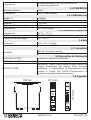
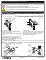
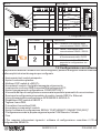
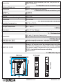
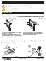
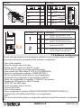
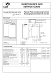
·
MANUALE DI INSTALLAZIONE
ED USO
Lingua manuale
Prodotto
Italiano
Z-107E
Adattatore da Ethernet a
RS485 o RS232
Funzioni
Indice:
1.0 Disclaimer
2.0 Descrizione e
Caratteristiche generali
Pag.
2
2
2.1 Descrizione
2.2 Caratteristiche generali
3.0 Specifiche tecniche
2
3.1 Generali
...
3.9 Ingombri
4.0 Istruzioni preliminari di utilizzo
5.0 Installazione
4
4
5.1 Installazione e rimozione dalla guida
DIN 46277
6.0 Collegamenti elettrici
5
6.1 Alimentazione
6.2 RS485
6.3 Ethernet
6.4 RS232
7.0 Configurazione e impostazioni
6
7.1 DIP-switch frontale
7.2 Configurazione con software
8.0 Esempi applicativi
6
8.1 Remote Com port
8.2 Tunnel point to point
8.3 Tunnel point to Multipoint
8.4 Descrizione
9.0 Led di indicazione
10.0 Accessori
8
8
Seneca s.r.l.
Produttore
Sede Amministrativa: Via Germania, 34 - 35127 - Z.I. CAMIN - PD - IT
Sede Operativa: Via Svizzera, 17 - 35127 - Z.I. CAMIN - PD - IT
Tel. +39.049.8705355 - 8705359 - Fax +39.049.8706287
Web
www.seneca.it
Mail
[email protected]
[email protected]
Questo documento è di proprietà SENECA srl. La duplicazione e la riproduzione sono vietate, se non
autorizzate. Il contenuto della presente documentazione corrisponde ai prodotti e alle tecnologie
descritte. I dati riportati potranno essere modificati o integrati per esigenze tecniche e/o commerciali.
MI002191-I-E
ITALIANO 1/8
1.0 DISCLAIMER
Prima di effettuare qualsiasi operazione è obbligatorio leggere tutto il contenuto
del presente Manuale. Il modulo deve essere utilizzato esclusivamente da
tecnici qualificati nel settore delle installazioni elettriche; é responsabilità
dell'installatore assicurarsi che l'installazione risponda alle normative di
sicurezza previste dalla legge.
La riparazione del modulo o la sostituzione di componenti danneggiati deve
essere effettuata dal Costruttore.
Le condizioni di garanzia decadono se il modulo è manomesso.
Seneca S.r.l. www.seneca.it
Sede Amministrativa: Via Germania, 34 - 35127 Z.I. CAMIN - PD - IT
Sede Operativa: Via Svizzera, 17 - 35127 Z.I. CAMIN - PD - IT
2.0 DESCRIZIONE E CARATTERISTICHE GENERALI
2.1 Descrizione
Lo Z107E adatta il segnale di comunicazione ethernet in un segnale seriale RS485 o
RS232, può essere usato come porta di comunicazione seriale remota attraverso il
protocollo TCP o UDP della rete ethernet.
2.2 Caratteristiche generali
·
·
·
·
·
·
·
·
·
Comunicazione da ethernet a RS485 o RS232 attraverso una porta di comunicazione
virtuale (REMOTE COM PORT).
Comunicazione POINT TO POINT attraverso la connessione ethernet con protocollo
TCP o UDP.
Comunicazione POINT TO MULTIPOINT attraverso la connessione ethernet.
Velocità di comunicazione ethernet: 10Mbit/s o 100Mbit/s
Porta Ethernet 10-BaseT e 100-BaseT con protocollo TCP o UDP
Massimo baud rate impostabile 115200 Bps.
Isolamento degli ingressi di 500 Vac rispetto ai restanti circuiti in bassa tensione.
Rapido montaggio su guida DIN 46277.
Morsetti estraibili a sezione 2.5 mm.
3.0 SPECIFICHE TECNICHE
3.1 Generali
Alimentazione
12.. 28 Vac, 12.. 40 Vdc
Potenza dissipata
1,2 W
Isolamento
500 Vac
3.2 COM RS485
Baud rate massimo
115 k
MI002191-I-E
ITALIANO 2/8
Morsetto estraibile ( M4, M5, M6) o IDC10
(connettore posteriore)
Connessione
3.3 COM RS232
Baud rate massimo
Connessione
115 K
DB9-F a lato scheda.
3.4 COM Ethernet
10 Base T
100 Base T
Protocollo
Massima distanza di collegamento
Connessione
10 Mbit/s
100 Mbit/s
TCP, UDP
100 m
RJ 45 sul frontale
3.5 Condizioni ambientali
Temperatura
Umidità
Temperatura di stoccaggio
-20 °C.. +70 °C
30 ..90% a 40 °C non condensante
-40 .. +85°C
3.6 Box
Dimensioni
Scatola; grado di protezione
100 x 17,5 x 111 mm
Plastica nera, IP20
3.7 Connettori
IDC da 10 per bus seneca
Morsetti estraibili passo 5,08 mm
Connettori
3.8 Normative di riferimento
EN 61000-6-4/ 2007
EN 61000-6-2/ 2005
(emissione, ambiente industriale)
(immunità, ambiente industriale)
(sicurezza): Taluni circuiti devono essere isolati con
doppio isolamento dai circuiti sotto tensione
pericolosa. Il trasformatore di alimentazione deve
essere a norma EN 60742:«Trasformatori di
isolamento e trasformatori di sicurezza»
EN 61010-1/ 2001
3.9 Ingombri
17,5 mm
1 2 3
4 5 6
S
Run
Lnk
Act
111,0 mm
100 mm
Z107E
12
MI002191-I-E
ITALIANO 3/8
4.0 ISTRUZIONI PRELIMINARI DI UTILIZZO
Il modulo è progettato per essere installato su guida DIN 46277 (fig 1) in posizione verticale.
È vietato lavorare in presenza di tensione elettrica.
È vietato installare il modulo accanto ad apparecchi che generano calore.
L’uso e l’installazione sono consigliati a personale tecnico esperto
5.0 INSTALLAZIONE
Per installare / rimuovere lo Z-SUPPLY alla guida DIN 46277 eseguire le operazioni
ripostate sotto (Fig.1a e Fig.1b)
5.1 Installazione e rimozione dall guida DIN 46277
Fig. 1a
Fig. 1b
Z1
07
E
Eth
Ad ern
ap et
te RS
r 2
ET003401B
Z1
07
E
ET003401B
Eth
Ad ern
ap et
te RS
r 2
32
/R
RS
S4
C 23
85
PIN onn 2 Mo
e
DB ctio dbu
9 np s
o
2
Sig rt
3
na
Po
l
5
Tx
Mower
db Su
Rx
7
u p
Pow s c ply
Gn
8
o &
d
19 er su nne RS
Dat
CT
.. pp c 4
Z10a co
S
Con19.. 28 V ly tion 85
7E nnec RT
su 40 Vac
mp. dc
an tio S
dP n
C betw
CO ee
M n
po
rt
~1
W
2
GN
3
D
A(+
A
Z10
B
Re (-) 5
ar
co 6
nn
ec
GN
tor
D
Po
7E
dP n
C betw
CO e
M en
po
rt
Eth
Dipern
-swet C
itc OM
h te p
rm ort
in an
M ator d
1
1,2
4
)
wer
4
n
ly
AC
pp
ly
E
E
2
3
D
A(+
)
B()
nn
ern
et
Eth
Dipern
-swet C
itc OM
h te p
rm ort
in an
M ator d
1,2
4
5
6
ec
Pow
er
1
2
4 3
5
6
tor
Ru
Sup
ply
B
er
Lnk
Act
S
n
Ln
AC
+
Run
co
nn
.
to
Lnk
Act
Eth
ern
et
c
on
n.
SW
RS 1
(S 485
wit T
ch erm
1) in
ato
r
SW
RS 1
(S 485
wit T
ch erm
1) in
a
1 2 3
4 5 6
S
k
Le
d
Z1
07
E
Sup
ply
M ,3
4,5
,6
Ac
t
AC
-
Pow
Eth
1 2
+
ON
AC
07
Z1
07
1W
GN
co
1 2
Z1
ar
GN
D
Run
Le
d
Re
ON
Po
Su
M ,3
4,5
,6
Lnk
-
.~
A
1 2 3
4 5 6
S
Ac
t
pp
wer
2
3
5
6
S
Ru
Su
B
32
/R
RS
S4
C 23
85
PIN onn 2 Mo
e
DB ctio dbu
9 np s
o
2
Sig rt
3
na
Po
l
5
Tx
Mower
db Su
Rx
7
u p
Po s c ply
Gn
8
w o &
d
19 er su nne RS
Da
CT
.. p c 4
Z1 ta co
S
Co19.. 28 V ply tion 85
07 nn R
nsu 40 ac
E ect TS
mp Vd
an io
c
Z107E
Z107E
r
12
12
INSTALLAZIONE
1)Tirare verso l’esterno i quattro ganci
posti ai lati del modulo;
2) Inserire il modulo in uno slot libero nel bus
seneca;
3) Assicurarsi che i pin del connettore IDC10
siano correttamente inseriti nello slot;
4) Richiudere i ganci posti ai lati del modulo,
agganciandosi alla guida DIN.
RIMOZIONE:
1) Tirare verso l’esterno ogni gancio a lato
del modulo facendo leva con un cacciavite.
2) Aperti tutti i ganci estrarre il modulo
dalla guida delicatamente.
È importante inserire correttamente l’IDC10 sul bus Z-PC-DIN in quanto è polarizzato.
L’inserimento è agevolato dalla presenza di un’inserzione maschio/femmina tra connettore
IDC 10 e slot su guida DIN (Fig 1c e Fig 1d).
P.E.
Power supply
(AC-)
Power
Supply
AC-
AC
P.E
GN
B/L
D
SH
A/H
D
AC
+
.
-
Slot
Power supply
(AC+)
Power
Supply
AC+
CANH/A
GNDSHLD
Z-PC-DIN
Fig. 1c
IDC10
MI002191-I-E
Fig. 1d
ITALIANO 4/8
6.0 COLLEGAMENTI ELETTRICI
6.1 Alimentazione
Assicurarsi che lo Z107E sia spento prima di
procedere con qualsiasi operazione.
Fig. 2
Per alimentare lo Z107E è necessario usare
una tensione compresa tra 12.. 28 Vac, o
compresa tra 12.. 40 Vdc attraverso il
morsetto 2 e il morsetto 3.
6 5 4
3 2 1
In alternativa l’alimentazione può essere data
attraverso il connettore posteriore IDC10, nel
caso in cui si utilizzi lo Z-PC-DINAL.
6.2 RS 485
Fig. 3
La connessione RS485 è disponibile
attraverso il morsetto 4 (ground), 5 (A) e 6 (B).
Per i collegamenti è consigliato l’uso di cavo
schermato.
6 5 4
In alternativa la seriale RS485 può essere
data attraverso il connettore posteriore IDC10,
nel caso in cui si utilizzi lo Z-PC-DINAL.
3
GND
A (+)
B (-)
6.3 Ethernet
Fig. 4
Porta ethernet con connettore RJ 45 sul
frontale del modulo per una semplice
connessione al PC ; con velocità fino a 100
Mbit/s, con protocollo TCP e UDP.
Ethernet RJ45
6.4 RS 232
La porta seriale RS232 a lato dello Z107E può
essere usata per la normale comunicazione.
Viene usata anche per configurare lo Z107E
quando è in modalità di «BOOT»
Il cavo di connessione non deve superare i la
lunghezza di 3 metri. e deve essere di tipo pin
to pin. Il cavo dovrà essere come descritto
nella pagina seguente.
MI002191-I-E
Porta RS232
Fig. 5
ITALIANO 5/8
Dal PC
Allo Z107E
DESCRIZIONE PIN
PIN DESCRIZIONE
Rx
2
2
Tx
Tx
3
3
Rx
Gnd
5
5
Gnd
Rts
7
7
Cts
Cts
8
8
Rts
7.0 CONFIGURAZIONE E IMPOSTAZIONI
7.1 Dip-switch frontale
DIP-Switch
Z107E
Posizione Descrizione
OFF= Disabilita il terminatore della
comunicazione RS485 / RS232
ON= Abilita il terminatore della
comunicazione RS485 / RS232
12
OFF= Ripristina la normale modalità
di funzionamento dello Z107E
ON= Abilita la modalità «BOOT» che
permette la configurazione via
software
7.2 Configurazione con software
Alla prima accensione il modulo non sarà configurato, pertanto di seguito verranno elencate
delle semplici istruzioni da seguire per configuralo.
·
·
·
·
·
·
·
·
·
·
·
·
·
·
·
·
Assicurarsi che il modulo sia spento.
Aprire il contenitore plastico.
Abilitare il DIP-switch di « BOOT»
Accendere il modulo, il led giallo lampeggia velocemente.
Inserire solo ora il cavo DB9 che permette di collegarsi al PC.
Aprire il programma di configurazione: COMPOSITOR(*).
A seconda del tipo di configurazione necessaria impostare i parametri di comunicazione.
Scaricare la configurazione impostata, al modulo, tramite RS232 o Ethernet.
Una volta scaricata la configurazione SPEGNERE IL MODULO.
Disabilitare il DIP-switch di «BOOT».
Togliere il cavo DB9.
Connettere il connettore RJ45.
Accendere nuovamente il modulo.
Aprire il software di configurazione SERIAL TO ETHERNET CONNECTOR (SEC)*
Configurare secondo le proprie esigenze la porta COM Remota / Virtuale.
Fine.
(*) Per maggiori informazioni riguardo i software di configurazione consultare il CD di
configurazione SENECA.
MI002191-I-E
ITALIANO 6/8
8.0 ESEMPI APPLICATIVI
8.1 Remote COM port
Ethernet
Network
Z107E
Ethernet to RS485/RS232
ETHERNET
IDC10
RS485
RS485
Modbus
Network
8.2 Tunnel POINT to POINT
Ethernet
Network
Z107E
Ethernet to RS485/RS232
Z107E
Ethernet to RS485/RS232
ETHERNET
ETHERNET
IDC10
RS485
IDC10
RS485
RS485
Modbus
Network
8.3 Tunnel POINT to MULTIPOINT
Ethernet
Network
RS485 MASTER
SIDE
RS485 SLAVES
SIDE
Z107E
Ethernet to RS485/RS232
RS485
Modbus
Network
ETHERNET
IDC10
RS485
ETHERNET
IDC10
RS485
Z107E Ethernet to
RS485/RS232
RS485
Modbus
Network
Z107E
Ethernet to RS485/RS232
ETHERNET
IDC10
RS485
MI002191-I-E
RS485
Modbus
Network
ITALIANO 7/8
8.4 Descrizione
Gli schemi riportati sono degli esempi applicativi per le diverse modalità di funzionamento
dello Z107E, in particolare:
Esempio applicativo 1: REMOTE COM PORT, permette una comunicazione remota
tramite ethernet attraverso la creazione di una porta seriale virtuale per il bus RS485.
Esempio applicativo 2 : TUNNEL POINT to POINT, ripetitore di comunicazione ethernet tra
due Z107E.
Esempio applicativo 3 : TUNNEL POINT to MULTIPOINT; permette la connessione tra
diversi Z107E.
9.0 LED DI INDICAZIONE
LED
STATO
Lampeggio lento
Lampeggio veloce
Acceso fisso
Lampeggiante
Acceso
Spento
Run
Act
Lnk
SIGNIFICATO
Lo Z107E sta funzionando
È attiva la modalità «BOOT»
Traffico dati via Ethernet non presente
Traffico dati via Ethernet OK
Connessione Ethernet OK
Connessione Ethernet non presente
10.0 ACCESSORI
CODICE MAGAZZINO DESCRIZIONE
Z-PC-DIN
Z-PC-DIN
PM001450
PM002490
AL1-35
AL2-17,5
1-35
2-17,5
4-35
8-17,5
Supporto guida DIN con morsetti di alimentazione P=35 mm
Supporto guida DIN con morsetti di alimentazione P=17,5 mm
Supporto DIN 1 slot per connettore posteriore P=35 mm
Supporto DIN 2 slot per connettore posteriore P=17,5 mm
Supporto DIN 4 slot per connettore posteriore P=35 mm
Supporto DIN 8 slot per connettore posteriore P=17,5 mm
Cavo Ethernet 1,5 m
Cavo seriale RS232 (DB9M-DB9F), pin to pin
Smaltimento dei rifiuti elettrici ed elettronici (applicabile nell’Unione Europea e negli altri paesi con raccolta
differenziata). Il simbolo presente sul prodotto o sulla confezione indica che il prodotto non verrà trattato come rifiuto
domestico. Sarà invece consegnato al centro di raccolta autorizzato per il riciclo dei rifiuti elettrici ed elettronici.
Assicurandovi che il prodotto venga smaltito in modo adeguato, eviterete un potenziale impatto negativo
sull’ambiente e la salute umana, che potrebbe essere causato da una gestione non conforme dello smaltimento del
prodotto. Il riciclaggio dei materiali contribuirà alla conservazione delle risorse naturali. Per ricevere ulteriori
informazioni più dettagliate Vi invitiamo a contattare l’ufficio preposto nella Vostra città, il servizio per lo smaltimento
dei rifiuti o il fornitore da cui avete acquistato il prodotto.
MI002191-I-E
ITALIANO 8/8
·
INSTALLATION AND
USER’S GUIDE
Language manual
Product
English
Z-107E
Ethernet RS485 / RS232
adapter
Description
Contents:
1.0 Disclaimer
2.0 Description and
General features
Pag.
2
2
2.1 Description
2.2 General features
3.0 Technical specifications
2
3.1 General specifications
...
3.9 Module layout
4.0 Preliminary instructions for use
5.0 Installation
5.1 Installation on/ removal from
DIN 46277 rail
6.0 Electrical connections
4
5
6.1 Power supply
6.2 RS485
6.3 Ethernet
6.4 RS232
7.0 Congiguration and settings
7.1 Frontal DIP-switch
7.2 Software configuration
8.0 Application examples
6
6
8.1 Remote Com port
8.2 Tunnel point to point
8.3 Tunnel point to Multipoint
8.4 Description
9.0 Signalling leds
10.0 Accessories
8
8
Seneca s.r.l.
Manufacturer
Headquarter : Via Germania, 34 - 35127 - Z.I. CAMIN - PD - IT
Operations: Via Svizzera, 17 - 35127 - Z.I. CAMIN - PD - IT
Tel. +39.049.8705355 - 8705359 - Fax +39.049.8706287
Web
www.seneca.it
Mail
[email protected]
[email protected]
This document is property of SENECA srl. Duplication and reprodution are forbidden, if not authorized. Contents of
the present documentation refers to products and technologies described in it. All technical data contained in the
document may be modified without prior notice Content of this documentation is subject to periodical revision.
MI002191-I-E
ENGLISH 1/8
1.0 DISCLAIMER
Before executing any operation it’s mandatory to read all the content of this
user manual. Only electrical-skilled technicians can use the module
described in this user Manual; it is responsibility of the manufacturer to verify
that the installation complies with safety standards.
Only the Manufacturer is authorized to repair the module or to replace
damaged components.
No warranty is guaranteed in connection with faults resulting from improper
use, from modifications or repairs carried out by Manufacturer-unauthorised
personnel on the module, or if the content of this user Manual is not followed.
Seneca S.r.l. www.seneca.it
Headquarter: Via Germania, 34 - 35127 - Z.I.
CAMIN - PD - IT
Operations: Via Svizzera, 17 - 35127 Z.I. CAMIN - PD - IT
2.0 DESCRIPTION AND GENERAL FEATURES
2.1 Description
The Z107E adapts the Ethernet communication signal into a serial signal RS485 or RS232; it
can be used as a remote serial communication port via TCP or UDP port of the Ethernet
network.
2.2 General features
Ethernet to RS485 or RS232 communication through VIRTUAL COM PORT
Communication POINT TO POINT with ethernet TCP or UDP protocol connection
Communication POINT TO MULTIPOINT with ethernet connection
Ethernet communication velocity: 10Mbit/s o 100Mbit/
10-BaseT and 100-BaseT Ethernet port with TCP/IP communication protocol
Up to 115200 Bps for Modbus protocol.
500 Vac output isolation compared with other low voltage circuits
· Quick installation on DIN 46277 rail.
2
· Removable screw terminals with section of 2.5 mm
·
·
·
·
·
·
·
s
.
3.0 TECHNICAL SPECIFICATIONS
3.1 General specifications
Power supply
12.. 28 Vac, 12.. 40 Vdc
maximum power consumption
1,2 W
Isolation
500 Vac
3.2 RS485 communication port
Maximum Baud rate
115 k
MI002191-I-E
ENGLISH 2/8
Removable screw terminal ( M4, M5, M6) or IDC10
(rear connector)
Connection
3.3 Rs232 communication port
115 K
DB9-F in the side of the module.
Maximum Baud rate
Connection
3.4 Ethernet communication port
10 Base T
100 Base T
Protocol
Maximum connection lenght
Connection
10 Mbit/s
100 Mbit/s
TCP, UDP
100 m
RJ 45 front
3.5 Environmental condition
Operating temperature
Humidity
Storage temperature
-20 °C.. +70 °C
30 ..90% a 40 °C not condensing
-40 .. +85°C
3.6 Box
Dimension
Box; protection class
100 x 17,5 x 111 mm
Black plastic, IP20 (International protection)
3.7 Connectors
IDC with 10 pins for Seneca bus
Removable screw terminals: pitch 5.08 mm
Connectors
3.8 Standards
EN 61000-6-4/ 2007
EN 61000-6-2/ 2005
(electromagnetic emission, industrial environment)
(electromagnetic immunity, industrial environment)
(safety). All circuits must be isolated from the other
circuits under dangerous voltage with double isolation.
The power supply transformer must comply with EN
60742: «Isolated transformers and safety
transformers»
EN 61010-1/ 2001
3.9 Module layout
M6,Com.
DC Output:
24 Vdc
max 1,5 A
M11,gnd
M12,gnd
M9,+24Vdc
M10,gnd
M7,+24Vdc
M8,+24Vdc
1.5
Power good
M4,N.Open.
1 2 3
4 5 6
S
Run
Lnk
AC main input*:
100.. 260 Vac
50.. 60 Hz
[N]M3
[L]M1
Fuse
Power supply:
110.. 230 Vac, to
24 Vdc, 1,5A
Z107E
12
ET003481B
Z-SUPPLY
Act
111,0 mm
17,5 mm
100 mm
MI002191-I-E
ENGLISH 3/8
4.0 PRELIMINARY INSTRUCTIONS FOR USE
The module is designed to be installed on DIN 46277 rail (fig.1) in vertical position.
No operation on the module is allowed while it is power on.
It is forbidden to install the module near heat-emitting devices
It is reccomended that the use and installation operations are performed by an
electrical-skilled technician
5.0 INSTALLATION
To install/remove the Z-SUPPLY on/from DIN 46277 rail, execute the following operations
(Fig.1a and Fig.1b
5.1 Installation on/removal from DIN 46277 rail
Fig. 1a
Fig. 1b
Z1
07
E
Eth
Ad ern
ap et
te RS
r 2
ET003401B
Z1
07
E
ET003401B
Eth
Ad ern
ap et
te RS
r 2
32
/R
RS
S4
C 23
85
PIN onn 2 Mo
e
DB ctio dbu
9 np s
o
2
Sig rt
3
na
Po
l
5
Tx
Mower
db Su
Rx
7
u p
Pow s c ply
Gn
8
o &
d
19 er su nne RS
Dat
CT
.. pp c 4
Z10a co
S
Con19.. 28 V ly tion 85
7E nnec RT
su 40 Vac
mp. dc
an tio S
dP n
C betw
CO ee
M n
po
rt
~1
W
2
GN
3
D
A(+
A
Z10
B
Re (-) 5
ar
co 6
nn
ec
GN
tor
D
Po
7E
dP n
C betw
CO e
M en
po
rt
Eth
Dipern
-swet C
itc OM
h te p
rm ort
in an
M ator d
1
1,2
4
)
wer
4
n
ly
AC
pp
ly
E
E
2
3
D
A(+
)
B()
nn
ern
et
Eth
Dipern
-swet C
itc OM
h te p
rm ort
in an
M ator d
1,2
4
5
6
ec
Pow
er
1
2
4 3
5
6
tor
Ru
Sup
ply
B
er
Lnk
Act
S
n
Ln
AC
+
Run
co
nn
.
to
Lnk
Act
Eth
ern
et
c
on
n.
SW
RS 1
(S 485
wit T
ch erm
1) in
ato
r
SW
RS 1
(S 485
wit T
ch erm
1) in
a
1 2 3
4 5 6
S
k
Le
d
Z1
07
E
Sup
ply
M ,3
4,5
,6
Ac
t
AC
-
Pow
Eth
1 2
+
ON
AC
07
Z1
07
1W
GN
co
1 2
Z1
ar
GN
D
Run
Le
d
Re
ON
Po
Su
M ,3
4,5
,6
Lnk
-
.~
A
1 2 3
4 5 6
S
Ac
t
pp
wer
2
3
5
6
S
Ru
Su
B
32
/R
RS
S4
C 23
85
PIN onn 2 Mo
e
DB ctio dbu
9 np s
o
2
Sig rt
3
na
Po
l
5
Tx
Mower
db Su
Rx
7
u p
Po s c ply
Gn
8
w o &
d
19 er su nne RS
Da
CT
.. p c 4
Z1 ta co
S
Co19.. 28 V ply tion 85
07 nn R
nsu 40 ac
E ect TS
mp Vd
an io
c
Z107E
Z107E
r
12
12
INSTALLATION
1)Pull the four latchs (placed in the backside panel) outwards;
2) insert the module in a DIN rail free slot;
3) make sure that the IDC10-connector pins
are inserted on the slot correctly;
4) press the four latchs inwards.
REMOVAL
1) Pull the four latchs (placed in the backside panel) outwards, using a screwdriver;
2) pull out the module gently.
It’s important to insert the pins on the slot correctly because IDC10-connector is polarized;
this connection is facilitied by use of a female/male insertion between IDC10 connector and
DIN rail slot (Fig 1c and Fig 1d).
P.E.
Power supply
(AC-)
Power
Supply
AC-
AC
P.E
GN
B/L
D
SH
A/H
D
AC
+
.
-
Slot
Power supply
(AC+)
Power
Supply
AC+
CANH/A
GNDSHLD
Z-PC-DIN
Fig. 1c
IDC10
MI002191-I-E
Fig. 1d
ENGLISH 4/8
6.0 ELECTRICAL CONNECTIONS
6.1 Power supply
Make sure that the Z107E is power off before
executing any operations.
Fig. 2
To power the Z107E is necessary to use a
voltage between 12 .. 28 Vac or between 12 ..
40 Vdc through the terminal 2 and terminal 3.
6 5 4
Alternatively power supply can be provided
through the rear connector IDC10, for Z-PCDINAL bus.
3 2 1
6.2 RS 485
Fig. 3
The RS485 serial communication port is
available on the screw terminals 4 (ground),
5 (A) e 6 (B) as shown in Fig 4.
For the maximum performances it’s
recommended to use a specific shielded
cable.
6 5 4
Alternatively RS485 can be provided through
the rear connector IDC10, for Z-PC-DINAL
bus.
3
GND
A (+)
B (-)
6.3 Ethernet
Ethernet communication port with RJ 45 on
the front it’s used to connect by the PC.
Communication velocity up to 100 Mbit / s, with
TCP and UDP protocol.
Ethernet RJ45
6.2 RS 232
The Rs232 serial communication port is
available with DB9-F connector on the side of
Z107E .
It can be used to download the configuration
software in the Z107E when it is in «BOOT»
mode.
The lenght of the cable don’t have exceeded
the 3 m and it must be a pin to pin type. The
cable shall be as described in the following
page.
MI002191-I-E
Porta RS232
Fig. 5
ENGLISH 5/8
From PC
To Z107E
DESCRIPTION PIN
PIN DESCRIPTION
Rx
2
2
Tx
Tx
3
3
Rx
Gnd
5
5
Gnd
Rts
7
7
Cts
Cts
8
8
Rts
7.0 CONFIGURATION AND SETTINGS
7.1 Frontal Dip-switch
DIP-Switch
Z107E
Position
Description
OFF= Disable the terminetor of the
RS485 / RS232 communication.
12
ON= Enable the terminetor of the
RS485 / RS232 communication.
OFF= Restores the normal operation
mode of the Z107E
ON= Enable the «BOOT» mode that
let the software configuration
7.2 Software configuration
The first time the module is not configured, therefore in the following steps are present
some simple instruction to download the software configuration.
Turn off the module.
· Open the plastic side of the box.
· Enable the DIP-switch for «BOOT» mode
· Turn ON the module, the yellow led blink quickly.
· Now connect the DB9 cable (Z107E to PC)(PM002490).
· Open the configuration software: COMPOSITOR(*).
· Set the configuration parameters for yours application.
· Download the configuration to the module by RS232
· When the configuration is installed, TURN OFF the module.
· Disable the DIP-switch for «BOOT»mode.
· TAKE OFF the DB9 cable.
· Close the plastic side of the box.
· Connect the RJ45
· Turn on the module.
· Open configuration software: SERIALTOETHERNETCONNECTOR(SEC)(*)
· Configure the Virtual/RemoteCOM for yours application.
· End.
(*) For more information about a configuration software consult the seneca’s configuration
CD
·
MI002191-I-E
ENGLISH 6/8
8.0 ESEMPI APPLICATIVI
8.1 Remote COM port
Ethernet
Network
Z107E
Ethernet to RS485/RS232
ETHERNET
IDC10
RS485
RS485
Modbus
Network
8.2 Tunnel POINT to POINT
Ethernet
Network
Z107E
Ethernet to RS485/RS232
Z107E
Ethernet to RS485/RS232
ETHERNET
ETHERNET
IDC10
RS485
IDC10
RS485
RS485
Modbus
Network
8.3 Tunnel POINT to MULTIPOINT
Ethernet
RS485 SLAVES
Network
RS485 MASTER
SIDE
SIDE
Z107E
Ethernet to RS485/RS232
RS485
Modbus
Network
ETHERNET
IDC10
RS485
ETHERNET
IDC10
RS485
Z107E Ethernet to
RS485/RS232
RS485
Modbus
Network
Z107E
Ethernet to RS485/RS232
ETHERNET
IDC10
RS485
MI002191-I-E
RS485
Modbus
Network
ENGLISH 7/8
8.4 Description
The following diagrams shows some examples of applications for different operating
modes of the Z107E, in particular:
Application example 1: REMOTE COM PORT, allows to create a remote communication
via ethernet by creating a virtual serial COM port for RS485 or RS232 bus.
Application example 2 : TUNNEL POINT TO POINT, ethernet communication
repeater between two Z107E.
Application example 3 : TUNNEL POINT to MULTIPOINT; allows the connection between
more Z107E.
9.0 SIGNALLING LEDS
STATE
LED
Slow blink
Fast blink
On
Blinking
On
Off
Run
Act
Lnk
MEANING
The Z107E work properly
«BOOT» mode enable
No data transfer from Ethernet
Data on Ethernet OK
Connection OK
Ethernet not connected
10.0 ACCESSORIES
DESCRIPTION
CODE
AL1-35
AL2-17,5
1-35
2-17,5
4-35
8-17,5
Z-PC-DIN
Z-PC-DIN
PM001450
PM002490
DIN rail support with screw terminals P=35 mm
DIN rail support with screw terminals P=17,5 mm
DIN 1 slot support for rear connector P=35 mm
DIN 2 slot support for rear connector P=17,5 mm
DIN 4 slot support for rear connector P=35 mm
DIN 8 slot support for rear connector P=17,5 mm
Ethernet cable 1,5 m
RS232 cable (DB9M-DB9F), pin to pin
Disposal of Electrical & Electronic Equipment (Applicable throughout the European Union and other European
countries with separate collections programs). This symbol, found on your producr or on its packaging, indicates that
this product should not be treated as household waste when you wish to dispose of it. Instead, it should be handed
over to an applicable collection point for the recycling of electrical & electronic equipment. By ensuring this product is
didposed of correctly, you will help prevent potential negative consequences to the environment and human health,
which could otherwise be caused by inappropriate disposal of this product. The recycling of materials will help to
conserve natural resources. For more detailed information about the recycling of the product, please contact your
local city office, waste disposal service of the retail store where you purchased this product.
MI002191-I-E
ENGLISH 8/8