1
Installation & Programming Manual
Manuale di Installazione e Programmazione
Table of Contents
Introduction ........................................................................................................... 3
Operational Functions .......................................................................................... 3
Alarm / Tamper Indication ................................................................................... 3
Low Battery Indication ......................................................................................... 3
Supervision ......................................................................................................... 3
Pre Alarm Indication ............................................................................................ 3
Sounder Self Testing........................................................................................... 3
LED display ......................................................................................................... 3
Mounting the Sounder .......................................................................................... 4
Programming the sounder ................................................................................... 5
Step 1: Sounder/Receiver Communication Set up .............................................. 5
Step 2: Setting the Sounder Parameters............................................................. 6
Strobe Control ............................................................................................... 6
Strobe Blink ................................................................................................... 6
Strobe Arm Squawk ...................................................................................... 6
Adjusting the Volume .................................................................................... 6
Muting Tamper .............................................................................................. 6
Setting Supervision Time .............................................................................. 7
Pre Alarm indication ...................................................................................... 7
Step 3: Testing the Sounder ............................................................................... 7
Communication Test ..................................................................................... 7
Diagnostics.................................................................................................... 8
Replacing Batteries .............................................................................................. 8
Technical Information........................................................................................... 8
Electrical ............................................................................................................. 8
Wireless .............................................................................................................. 8
Environment ........................................................................................................ 8
Ordering Information ............................................................................................ 8
2
Wireless Sounder Instructions
Introduction
RISCO Group's two-way wireless Prosound Sounder is designed to extend the
signaling capabilities of RISCO Group's WisDom and Agility wireless systems. The
wireless sounder offers an easy and flexible solution for quick installation. The
sounder is powered by its own batteries and communicates wirelessly with the
security panel.
Operational Functions
Alarm / Tamper Indication
Upon an alarm condition, the sounder will be activated for a period of time defined
by the system (Bell Time Out parameter).
Low Battery Indication
Upon a low battery condition a trouble indication is sent to the panel.
There are 2 types of low battery indications:
Radio low battery
Speaker low battery
Supervision
Each sounder can be defined to be supervised by the panel. The system generates
a local trouble signal identifying the sounder whose signal is not received during a
predefined time, followed by a report to the Alarm Receiving Center (if defined).
Pre Alarm Indication
When an entry time starts, the system transmits a pre-alarm signal to the sounder.
If the system is disarmed before the entry delay time expires, a cancellation signal
is sent to the sounder.
If the sounder does not receive a cancellation signal within the entry delay time, the
sounder will be activated.
Sounder Self Testing
Once placing all batteries in the battery holders or pressing on the reset switch
located on the PCB (with the tamper switch open), the sounder performs a
functional self test indicated by a strobe flash squawk sound.
LED display
The wireless sounder has 2 indication LEDs located on the PCB. These LEDs
are enabled when the tamper is open and 10 minutes after the tamper is
closed.
Red: Indicates transmission
Yellow: Indicates a low battery
Red and Yellow (3 seconds): Confirms successful learning.
Wireless Sounder Instructions
3
Mounting the Sounder
To mount the sounder follow this procedure:
1. Open the front cover by removing the case locking screw located at the bottom of
the unit.
2. Hold the mounting pattern template (supplied) against the wall and mark the
locations for the mounting holes (4 mounting holes are available). Drill the desired
mounting holes and place the screw anchors.
3. Mount the back unit to the wall using the supplied screws, 3.9mm, 32mm length
screws (DIN 7981 3.9X32 ZP).
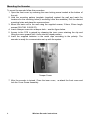
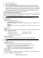
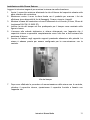
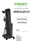
4. Insert a tamper screw into a tamper hole -- see the figure below.
5. Access to the PCB is gained by releasing the inner cover retaining the clip and
lifting the cover upward until it locks into the raised position.
6. Insert the supplied batteries in the metal clips according to the polarity. The
sounder is ready for communication set up with the system.
Tamper Screw
7. After the sounder is trained, Close the inner cover, re-attach the front cover and
lock the Cover Screw Assembly.
4
Wireless Sounder Instructions
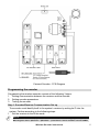
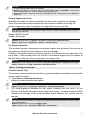
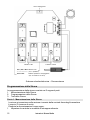
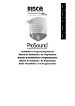
External Sounder - PCB Diagram
Programming the sounder
Programming the wireless sounder consists of the following 3 steps:
1. Setting communication between the receiver and the sounder
2. Setting sounder parameters
3. Testing the sounder
Step 1: Sounder/Receiver Communication Set up
The sounder must identify itself to the system's receiver by writing its ID into the
system. Perform according to the following steps:
1. Set the receiver to the Write mode.
NOTE:
In the WisDom , as a first step, you need to allocate the sounder in the following programming location:
Main Engineer menu> 9)Devices > 2)Sounder > 1) Allocation > Select sounder> Choose ODWS1
Wireless Sounder Instructions
5
2.
3.
4.
5.
6.
Select the sounder's ID.
Unpack the supplied batteries.
Insert two speaker batteries and three Radio batteries into the batteries holders.
After a squawk is heard and the sounder's strobe flashes you have 10 seconds to
press on the tamper switch for at least 3 seconds. If the sounder is successfully
recognized, the system will sound a confirmation beep and the sounder will initiate
a second squawk sound and the 2 LEDs on the sounder will flash for 3 seconds.
Repeat the process for other sounders in the system.
Step 2: Setting the Sounder Parameters
Each sounder can be defined with different sets of parameters. The following table
describes the list of parameters of the sounder.
NOTE:
For the specific programming location of each parameter refer to the system manuals.
Strobe Control
Defines the Strobe operation mode:
Always Off: The strobe is deactivated
Follow Bell (Default): The strobe is activated when the sounder bell is
triggered
Follow Alarm: The strobe is activated when an alarm event occurs in the
system
Strobe Blink
Defines the number of times the strobe will flash per minute (Default 40 times per
minute). Strobe Blink options:
[1] 20 times per minute
[4] 50 times per minute
[2] 30 times per minute
[5] 60 times per minute
[3] 40 times per minute (Default)
Strobe Arm Squawk
The time that strobe blinking will continue when set is performed (Default: 05)
NOTE:
If the sounder’s squawk strobe is defined as NO (Refer to the Allocation section) this parameter will be
ignored.
Adjusting the Volume
Defines the sounder sound volume for the following system modes:
Exit / Entry: The sound produced during Exit/Entry time (Default: 0)
Alarm: The sound produced during alarm (Default: 9)
Squawk: The sound produced during squawk sounds (Default: 9)
The sound volume range is between 0 (silent) to 5 (maximum volume).
Muting Tamper
This feature disables a tamper alarm from the sounder and it is recommended to be
used when replacing the sounder's batteries.
6
Wireless Sounder Instructions
NOTES:
1. An ongoing tamper alarm will not be disabled.
2. WisDom: This feature is controlled under the Engineer Menu (Quick key [9][2][5]). Tamper alarm
will be disabled during the current installation programming period.
3. Agility: This feature is controlled under the Grand Master menu. Tamper alarm will be disabled for
20 minutes.
Setting Supervision Time
Specifies how often the system generates a supervision request to the sounder.
If any of the sounders does not respond to the request at least once during the
receiver supervision time, the system will regard the accessory as lost.
NOTE:
The receiver supervision time should be higher than the sounder supervision time in order to
eliminate false lost event.
Range: 00-255 minutes
Default: 58 minutes
NOTE:
WisDom: Engineer menu: 1) System > 1) Timers > 9) Accessory supervision time
Agility: Engineer menu: 1) System > 1) Timers > TX supervision
Pre Alarm indication
This wireless sounder incorporates a pre-alarm feature that enhances the security of
the system by producing a local alarm in case of sabotage.
If defined, the system sends a pre-alarm signal to the sounder at the beginning of the
entry delay. If the sounder does not receive a cancellation signal from the system at
the end of the entry time, the sounder goes into alarm mode.
NOTE:
WisDom (Ver 4.25): Engineer menu Quick key 1) System> 2)Parameters> 35)Sounder Pre alarm
Agility: Engineer menu [1][2] > Advanced > Sounder Pre alarm
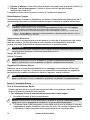
Step 3: Testing the Sounder
Communication Test
The sounder communication test performs a communication test between the sounder
receiver and the system.
To perform a communication test:
1. Access the communication test option.
NOTE:
WisDom: Engineer menu > 9) Devices > 2) Sounders > 3) Communication test
Agility: Engineer menu > 2) Testing > 5) Sounder > 1) Communication test
2.
The value displayed indicates the last signal received from the siren ( In the
WisDom it indicates the signal received during the test). A number between 00-99
indicates the strength of the communication signal between the system and the
sounder.
NOTE:
For successful communication, the strength of the signal should be higher that the sounder receiver
noise threshold level.
WisDom: Engineer menu quick key [9][2][4], Agility
Agility: Engineer menu> 2)Testing > 1)Main unit > 1)Calibration).
Wireless Sounder Instructions
7
Diagnostics
The Diagnostics menu enables to test parameters reflecting the operation of the
sounder:
Speaker batteries voltage: Tests the selected sounder’s speaker batteries voltage
Radio batteries voltage: Tests the selected sounder’s radio's batteries voltage
Sounder version: Displays information regarding the sounder's version
NOTE:
WisDom: User menu: 4) Maintenance > 7) Sounders > 1) Diagnostics
Agility: Engineer menu > 2) Testing > 5) Sounder > 2) Battery test > 3)Version
The diagnostic features can also be performed from the Upload/Download software, locally or
remotely.
Replacing Batteries
1.
2.
3.
4.
5.
Before opening the sounder it is advised to silence the tamper alarm using the
Tamper Mute option.
Open the front cover by removing the case locking screw located at the unit’s bottom.
Access to the PCB is gained by releasing the inner cover retaining the clip and
lifting the cover upward until it locks into the raised position.
Remove the old batteries from the metal clips and replace them with the new ones.
Pay attention to the polarity. The sounder is ready for communication set up with
the system
Replace the front cover and lock the screw.
NOTES:
Dispose of old batteries according to your local regulations.
Risk of explosion if battery is replaced by an incorrect type.
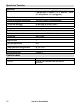
Technical Information
Electrical
Power supply
Battery lifetime
Sounder volume
Strobe lens
Flash frequency
Dimensions (HxWxD)
Weight (without batteries)
Wireless
5 x CR123, 3V Lithium batteries
3 batteries for the wireless system, 2 bat. for signalling
3 years (typical)
105 dB @ 1 meter (3.3") - adjustable
Polycarbonate
60 times per minute (max.)
30.5 cm X 21.8 cm X 11.6 cm (12 x 8.58 x 4.57 inch)
1.189Kg Kg (2.62129 lbs)
Wireless technology
Frequency
Range
Environment
Bidirectional narrow band
868 MHz
150m (492’) Line of sight
Temperature range
IP class
- 25°C to 60°C
IP 44
Monitoring
YES
Modulation Type ASK
Environment class Class IV
Ordering Information
Model
RWS20
8
Description
2 way External Wireless Sounder,433 / 868.65 MHz
Wireless Sounder Instructions
Indice dei Contenuti
Introduzione ........................................................................................................ 10
Funzioni Operative.............................................................................................. 10
Indicazione Allarme / Tamper............................................................................ 10
Indicazione di Batteria Scarica .......................................................................... 10
Supervisione ..................................................................................................... 10
Indicazione di Preallarme .................................................................................. 10
Auto-Diagnosi.................................................................................................... 10
Indicatori LED nella fase di Installazione........................................................... 10
Installazione della Sirena Esterna ..................................................................... 11
Programmazione della Sirena ............................................................................ 12
Punto 1: Memorizzazione della Sirena .............................................................. 12
Punto 2: Programmazione della Sirena............................................................. 13
Lampeggiante.............................................................................................. 13
Numero Lampeggi ....................................................................................... 13
Lampeggio all’inserimento ........................................................................... 13
Regolazione del Volume ............................................................................. 13
Disabilitazione Tamper ................................................................................ 14
Supervisione Accessori ............................................................................... 14
Segnale di Preallarme Sirena ...................................................................... 14
Punto 3: Test della Sirena ................................................................................. 14
Test di Comunicazione Radio:..................................................................... 14
Diagnostica:................................................................................................. 15
Sostituzione delle Batterie ................................................................................. 15
Specifiche Tecniche ........................................................................................... 16
Codici Prodotto ................................................................................................... 16
Istruzioni Sirene Radio
9
Introduzione
La sirena via radio bidirezionale da esterno di RISCO Group è stata realizzata per
ampliare la gamma di accessori radio dei sistemi WisDom e Agility. Le sirene radio
offrono una soluzione semplice e flessibile per velocizzare l’installazione dei dispositivi
di segnalazione allarme locali. Le sirene sono autoalimentate con batterie al litio e
comunicano via radio con le centrali.
Funzioni Operative
Indicazione Allarme / Tamper
Al verificarsi di una condizione di allarme l’altoparlante della sirena verrà attivato per il
periodo di tempo definito dalla programmazione della centrale (Timers, Tempo Sirena).
Indicazione di Batteria Scarica
Al verificarsi di una condizione di batteria scarica la sirena trasmette questa
informazione alla centrale.
Ci sono 2 diverse informazioni riguardanti l’anomalia di batteria scarica:
•
Batteria scarica sezione radio (modulo RTX)
•
Batteria scarica altoparlante/speaker
Supervisione
Ogni sirena può essere programmata per essere supervisionata dalla centrale. Le
centrali WisDom e Agility generano una segnalazione locale di anomalia relativa alla
specifica sirena dalla quale non hanno ricevuto segnali entro una finestra di tempo
predefinita. Questa anomalia può anche essere trasmessa alla Società di Ricezione
Allarmi MS tramite una comunicazione digitale dell’evento (se programmata l’opzione
relativa).
Indicazione di Preallarme
Appena inizia il tempo di ingresso per il disinserimento del sistema, la centrale trasmette
un segnale di preallarme alla sirena.
Se il sistema viene correttamente disinserito prima dello scadere del tempo di ingresso
la centrale trasmette alla sirena un segnale di cancellazione del preallarme.
La sirena entrerà in condizione di allarme attivandosi se non riceve dalla centrale il
segnale di cancellazione del preallarme entro il tempo di ritardo in ingresso.
Auto-Diagnosi
Dopo aver inserito le batterie, alla pressione del tasto reset posizionato sulla scheda
elettronica della sirena, quest’ultima effettua una auto-diagnosi.
Il lampeggiante si attiverà e l’altoparlante emetterà un breve tono acustico.
Questo test può essere anche attivato da remoto utilizzando il software di teleassistenza
di RISCO Group o la tastiera via radio bidirezionale (solo Agility).
Indicatori LED nella fase di Installazione
La sirena ha 2 LED posizionati sulla scheda elettronica. Questi LED vengono abilitati
quando l’interruttore tamper viene aperto e restano abilitati per 10 minuti dopo che il
tamper viene richiuso.
Solo LED Rosso: Indica una fase di trasmissione
Solo LED Giallo: Indica batteria scarica
LED Rosso e Giallo (3 secondi): Conferma autoapprendimento
10
Istruzioni Sirene Radio
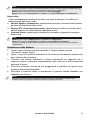
Installazione della Sirena Esterna
Leggere le istruzioni seguenti per montare la sirena via radio da esterno.
1. Aprire il coperchio anteriore allentando la vite di blocco del coperchio situata nella
parte inferiore del contenitore.
2. Mantenere contro il muro la dima fornita con il prodotto per marcare i fori da
effettuare (sono disponibili 4 fori di fissaggio). Forare e inserire i tasselli.
3. Montare la base del contenitore al muro utilizzando le viti fornite (3.9mm, 32mm di
lunghezza DIN 7981 3.9X32 ZP).
4. Inserire la vite del tamper nel foro predisposto per il tamper come mostrato nella
figura in basso.
5. L’accesso alla scheda elettronica si ottiene sbloccando con l’apposita clip il
coperchio interno e aprendolo completamente verso l’alto fino a farlo arrivare alla
posizione di blocco.
6. Inserire le batterie negli apposite supporti prestando attenzione alla polarità. La
sirena è adesso pronta per essere configurata per la comunicazione con la
centrale.
Vite del tamper
7.
Dopo aver effettuato le procedure di memorizzazione della sirena con la centrale,
chiudere il coperchio interno, riposizionare il coperchio frontale e fissarlo con
l’apposita vite.
Istruzioni Sirene Radio
11
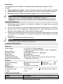
LED Lampeggiante
Indicatori LED
Pulsante di reset
BT1, BT2 e BT3: Batterie RTX
(3V, in parallelo)
BT4 e BT5:
Batterie Speaker e Lampeggiante
(6V, connessione in serie)
Schema scheda elettronica – Sirena esterna
Programmazione della Sirena
La programmazione della sirena consiste nei 3 seguenti punti:
1. Memorizzazione della Sirena
2. Programmazione della Sirena
3. Test della Sirena
Punto 1: Memorizzazione della Sirena
La sirena si memorizza nella sezione ricevente della centrale facendogli trasmettere
il proprio ID (numero di serie).
Eseguire la memorizzazione come segue:
1. Impostare la centrale in modalità di autoapprendimento.
12
Istruzioni Sirene Radio
Nota:
Nella centrale WisDom, per prima cosa dovete accedere al seguente menù per memorizzare la
sirena:
Programmazione Tecnica 9) Accessori 2) Sirena 1) Memorizzazione Sirena Selezionare l’ID e il TIPO ID = 01 TIPO = ODWS1
Per la centrale Agility premere il tasto di memorizzazione rapida o fare riferimento al manuale tecnico
della centrale.
2.
3.
4.
5.
6.
Selezionare l’ID della sirena da memorizzare.
Aprire la confezione delle batterie (fornite).
Inserire le 2 batterie dello speaker e le 3 batterie della sezione trasmittente negli
appositi alloggiamenti.
Dopo aver udito un tono dello speaker dalla sirena e l’attivazione del lampeggiante,
dovrete premere entro 10 secondi e per almeno 3 secondi, il tamper. La corretta
memorizzazione viene confermata da un tono acustico emesso dalla centrale ed un
secondo tono acustico emesso dalla sirena con il lampeggio dei suoi due LED per
tre secondi.
Ripetere i precedenti passaggi per eseguire la memorizzazione di ulteriori sirene
radio.
Punto 2: Programmazione della Sirena
Ogni sirena può essere programmata con differenti parametri. La sezione seguente
indica i vari parametri programmabili per la sirena.
Nota:
Per le locazioni dei parametri, fare riferimento ai manuali d’installazione e programmazione delle centrali.
Lampeggiante
Programma il funzionamento del lampeggiante:
Sempre spento: Il lampeggiante è disattivato
Segue Sirena (Default): Il lampeggiante si attiva insieme alla sirena.
Segue Allarme: Il lampeggiante si attiva quando si verifica una condizione di
allarme nel sistema e rimane attivo fino al disinserimento del sistema.
Numero Lampeggi
Programma il numero di lampeggi al minuto del lampeggiante (Default: 40 volte al
minuto). Opzioni Lampeggi:
[1] 20 volte al minuto
[4] 50 volte al minuto
[2] 30 volte al minuto
[5] 60 volte al minuto
[3] 40 volte al minuto (Default)
Lampeggio all’inserimento
Tempo di attivazione del lampeggiante per segnalare l’inserimento del sistema
(Default: 05).
Nota:
Se il parametro “Toni Sirena all’Inserimento” è impostato sul NO (far riferimento ai Controlli di Sistema
delle Centrali) questa funzione verrà ignorata.
Regolazione del Volume
Imposta il livello del volume per i seguenti modi operativi:
Volume Ingresso/Uscita: volume del suono prodotto durante i tempi di ritardo in
ingresso e in uscita (Default: 0).
Istruzioni Sirene Radio
13
Volume In allarme: livello del volume durante una condizione di allarme (Default: 9).
Volume Toni in Inserimento: il livello di volume dei toni prodotti durante
l’inserimento (Default: 9).
Il range del volume va da 0 (nessun suono) a 9 (volume al massimo).
Disabilitazione Tamper
Questa funzione è usata per disabilitare un allarme Tamper generato dalla sirena ed è
raccomandata per essere utilizzata quando vengono sostituite le batterie della sirena.
Note:
1. Un allarme tamper già attivato non verrà tacitato.
2. WisDom: questa funzione si trova nel menù di Programmazione Tecnica (Tasti rapidi [9][2][5]).
L’allarme tamper verrà disabilitato per la sessione di programmazione corrente.
3. Agility: questa funzione viene attivata tramite il codice Grand Master nel menù per l’utente come
segue: * Grand Master Attività Funzioni Avanzate Escludi Tamper Sirena). L’allarme
tamper verrà disabilitato per 20 minuti.
Supervisione Accessori
Stabilisce con che frequenza la centrale genera un richiesta di supervisione alle sirene
radio del sistema. Se una delle sirene non risponde immediatamente la centrale
genera un evento di anomalia di comunicazione per la specifica sirena.
IMPORTANTE:
Il tempo di supervisione della centrale deve essere maggiore del tempo di supervisione degli accessori al
fine di evitare false segnalazioni di perdita del segnale degli accessori.
Range: 00-255 minuti
Default: 58 minuti
Nota:
WisDom: Programmazione Tecnica: 1) Sistema 1) Timers 9) Supervisione Accessori
Agility: Programmazione Tecnica: 1) Sistema 1) Timers 8) Supervisione Accessori
Segnale di Preallarme Sirena
Stabilisce se la centrale dovrà trasmettere un messaggio di pre-allarme all’inizio del
tempo di ritardo in ingresso. Se la sirena non riceverà la cancellazione del segnale di
pre-allarme allo scadere del tempo di ritardo in ingresso, andrà in allarme.
Nota:
WisDom: Programmazione Tecnica: 1) Sistema 2) Controlli 35) Pre-Allarme Sirena
Agility: Programmazione Tecnica: 1) Sistema 2) Controlli 2) Avanzati Pre-Allarme Sirena
Punto 3: Test della Sirena
Test di Comunicazione Radio:
Questa opzione attiva un test di comunicazione radio tra la sezione radio della
sirena e la sezione ricevente della centrale.
Per effettuare il test di comunicazione procedere come segue:
1. Accedere al menù di test comunicazione.
Nota:
WisDom: Programmazione Tecnica: 9) Accessori 2) Sirena 3) Test di Comunicazione Radio
Agility: Menù Tecnico: 2) Diagnostica 5) Sirene 1) Test di Comunicazione Radio
2.
14
Il Sistema rileva l’ultimo segnale ricevuto dalla sirena (con la Wisdom il segnale
visualizzato è quello richiesto al momento del test). Un numero compreso tra 00
e 99 indica il livello di segnale della comunicazione tra i due dispositivi.
Istruzioni Sirene Radio
Nota:
Per una comunicazione ottimale ed affidabile nel tempo il livello di segnale ricevuto dovrebbe essere più
alto del livello di rumore rilevato dal ricevitore della sirena durante la calibrazione.
WisDom: vedere la specifica funzione attivabile con i tasti rapidi [9][2][4]
Agility: Menù Tecnico: 2) Diagnostica 1) Sirene 1) Livello Interferenza 2) Calibrazione .
Diagnostica:
Il menù di diagnostica permette di verificare una serie di parametri che riflettono il
funzionamento delle sirene radio.
Batterie Speaker (altoparlante): questa funzione verifica la tensione delle batterie
dedicate all’altoparlante della sirena.
Batterie RTX (ricetrasmettitore radio): questa funzione verifica la tensione delle
batterie dedicate al ricetrasmettitore radio della sirena.
Versione Sirena: questo menù visualizza le informazioni riguardanti la versione
della sirena.
Nota:
WisDom: menù Utente: 4) Manutenzione 7) Sirene 1) Diagnostica.
Agility: menù Tecnico: 2) Diagnostica 5) Sirene 2) Test Batteria, 5) Versione.
La funzione di diagnostica può essere effettuata anche localmente o da remoto tramite il software di
teleassistenza
Sostituzione delle Batterie
1.
2.
3.
4.
5.
Prima di aprire la sirena conviene escludere il Tamper usando l’opzione
“Esclusione Tamper Sirena”.
Aprire il coperchio anteriore allentando la vite di blocco del coperchio situata nella
parte inferiore del contenitore.
L’accesso alla scheda elettronica si ottiene sbloccando con l’apposita clip il
coperchio interno e aprendolo completamente verso l’alto fino a farlo arrivare alla
posizione di blocco.
Rimuovere le batterie vecchie dai loro alloggiamenti e sostituirle con quelle nuove
prestando attenzione alla polarità.
Richiudere il coperchio interno e riposizionare il coperchio frontale fissandolo con
l’apposita vite di blocco.
NOTE:
Utilizzare la corretta procedura di smaltimento delle batteria in conformità alle normative vigenti.
L’utilizzo di batterie di tipologia diversa può generare lo scoppio delle stesse.
Istruzioni Sirene Radio
15
Specifiche Tecniche
Elettriche
Alimentazione
Durata batterie
Pressione acustica altoparlante
Lente lampeggiatore
Frequenza lampeggi
Dimensioni: (LxHxP)
Peso
Radio
Tipologia sezione radio
Frequenza
Portata radio:
Supervisione
Tipo di modulazione
Ambientali
Temperatura di funzionamento
Grado di protezione IP
Classe ambientale
5 batterie al litio tipo CR123A da 3 Volt (3 batterie
in parallelo per il modulo RTX e 2 batterie in serie
per l’altoparlante e il lampeggiante)
3 anni (durata media)
105 dB a 1 metro (programmabile)
Policarbonato
60 lampeggi al minuto (max.)
30.5 cm X 21.8 cm X 11.6 cm
1.189Kg
Bidirezionale in Banda stretta
868,65 MHz
Portata ottica 150 m
Si
ASK
da -25° a 60°
IP 44
Classe IV
Codici Prodotto
Modello
RWS20
16
Descrizione
Sirena radio bidirezionale da esterno,
868MHz.
Istruzioni Sirene Radio
RTTE Compliance Statement
Hereby RISCO Group declares that this wireless sounder is in compliance with the
essential requirements and other relevant provisions of Directive 1999/5/EC.
For the CE Declaration of Conformity please refer to our website: www.riscogroup.com.
FCC Note:
This equipment has been tested and found to comply with the limits for a Class B digital
device, pursuant to Part 15 of the FCC rules. These limits are designed to provide
reasonable protection against harmful interference in a residential installation. This
equipment generates, uses and can radiate radio frequency energy and, if not installed
and used in accordance with the instructions, may cause harmful interference to radio
communications. However, there is no guarantee that interference will not occur in a
particular installation. If this equipment does cause harmful interference to radio or
television reception, which can be determined by turning the equipment off and on, the
user is encouraged to try to correct the interference by one or more of the following
measures:
a) Reorient or relocate the receiving antenna.
b) Increase the separation between the equipment and receiver.
c) Connect the equipment to an outlet on a circuit different from that to which the
receiver is connected.
d) Consult the dealer or an experienced radio/TV technician.
FCC ID: JE4RWRT433
IC: 6564A-RWRT433
FCC Warning
The manufacturer is not responsible for any radio or TV interference caused by
unauthorized modifications to this equipment. Such modifications could void the user's
authority to operate the equipment.
RISCO Group Limited Warranty
RISCO Group Ltd. and its subsidiaries and affiliates ("Seller") warrants its products to
be free from defects in materials and workmanship under normal use for 24 months
from the date of production. Because Seller does not install or connect the product and
because the product may be used in conjunction with products not manufactured by
the Seller, Seller cannot guarantee the performance of the security system which uses
this product. Seller's obligation and liability under this warranty is expressly limited to
repairing and replacing, at Seller's option, within a reasonable time after the date of
delivery, any product not meeting the specifications. Seller makes no other warranty,
expressed or implied, and makes no warranty of merchantability or of fitness for any
particular purpose.
In no case shall seller be liable for any consequential or incidental damages for breach
of this or any other warranty, expressed or implied, or upon any other basis of liability
whatsoever.
Seller's obligation under this warranty shall not include any transportation charges or
costs of installation or any liability for direct, indirect, or consequential damages or
delay.
Seller does not represent that its product may not be compromised or circumvented;
that the product will prevent any personal injury or property loss by burglary, robbery,
fire or otherwise; or that the product will in all cases provide adequate warning or
protection. Buyer understands that a properly installed and maintained alarm may only
reduce the risk of burglary, robbery or fire without warning, but is not insurance or a
guaranty that such will not occur or that there will be no personal injury or property loss
as a result.
Consequently seller shall have no liability for any personal injury, property damage or
loss based on a claim that the product fails to give warning. However, if seller is held
liable, whether directly or indirectly, for any loss or damage arising from under this
limited warranty or otherwise, regardless of cause or origin, sellers maximum liability
shall not exceed the purchase price of the product, which shall be complete and
exclusive remedy against seller.
No employee or representative of Seller is authorized to change this warranty in any
way or grant any other warranty.
WARNING: This product should be tested at least once a week.
Contacting RISCO Group
RISCO Group is committed to customer service and product support. You can contact
us through our website www.riscogroup.com or as follows:
United Kingdom
Tel: +44-(0)-161-655-5500
[email protected]
USA
Tel: +1- 631-719-4400
[email protected]
Italy
Tel: +39-02-66590054
[email protected]
Brazil
Tel: +1-866-969-5111
[email protected]
Spain
Tel: +34-91-490-2133
[email protected]
China
Tel: +86-21-52-39-0066
[email protected]
France
Tel: +33-164-73-28-50
[email protected]
Poland
Tel: +48-22-500-28-40
[email protected]
Belgium
Tel: +32-2522-7622
[email protected]
Israel
Tel: +972-3-963-7777
[email protected]
All rights reserved.
No part of this document may be reproduced in any form without prior written
permission from the publisher.
© RISCO Group 05/11
5IN1540