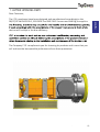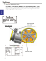
1
italiano
MANUALE D’USO E MANUTENZIONE
MANUEL D’UTILISATION ET D’ENTRETIEN
BEDIENUNGS-UND WARTUNGSANLEITUNG
MANUAL DE USO Y MANUTENCIÒN
ITG 160
Italian Top Gears s.r.l.
ITG 160
rev. 01
Via G. B. Tiepolo, 21
31021 - Mogliano Veneto (TV)
Via G. Falcone, 8
42020 - Borzano di Albinea - (RE)
Italia
Tel.: 0039 0522 350155
[email protected] - www.top-gears.it
english
OPERATION AND MAINTENANCE MANUAL
italiano
03
02
01
Edizione originale - Original edition
REV.
PAGINE - SHEETS
Marzo 2013
DATE
- 1.3 -
italiano
INDICE
1.
LETTERA ALLA CONSEGNA.........................................................................
1.
5
2.
IDENTIFICAZIONE MACCHINA.....................................................................
1.
6
3.
GARANZIA......................................................................................................
1.
7
4.
NOTE GENERALI ALLA CONSEGNA............................................................
1.
8
5.
AVVERTENZE PER LA SICUREZZA..............................................................
1.
9
6.
PRESCRIZIONI DI SICUREZZA.....................................................................
1.
10
7.
CARATTERISTICHE TECNICHE....................................................................
1.
13
8.
TRASPORTO..................................................................................................
1.
14
9.
NOTE PER L'INSTALLAZIONE......................................................................
1.
17
1.
21
9.1 ISTRUZIONE ROTAZIONE MOTORE
9.2 ISTRUZIONE MONTAGGIO ENCODER
9.3 LIVELLO OLIO
10.
LUBRIFICAZIONE DEGLI ARGANI................................................................
10.1 SOSTITUZIONE DELL’OLIO
10.2 CONTROLLO DEL LIVELLO DELL’OLIO
11.
COLLEGAMENTI ELETTTRICI.......................................................................
1.
23
12.
AVVIAMENTO DELL'ARGANO......................................................................
1.
28
MANUTENZIONE...........................................................................................
1.
30
1.
34
13.
13.1 PREREGOLAZIONE DEL FRENO
13.2 REGOLAZIONE DEL FRENO
13.3 CONTROLLO DELLA CORSA
13.4 INTERVENTI DI MANUTENZIONE OBBLIGATORI
14.
MANOVRA A MANO DI EMERGENZA..........................................................
14.1 AVVERTENZE
14.2 ISTRUZIONI PER LA MANOVRA A MANO DI EMERGENZA
- 1.4
italiano
1. LETTERA ALLA CONSEGNA
applicabile.
.
1.5 -
italiano
2. IDENTIFICAZIONE MACCHINA
Per qualsiasi comunicazione inerente ad una delle nostre unità di trazione,
indicate sempre il numero di matricola e tenete a disposizione anche quelli
Targhetta dati elettromagnete
Targhetta motore
Tipo macchina:
Matricola:
Ins. class:
Riduzione:
Tipo motore:
Kw:
Hz:
A /
RPM:
Anno:
F
Encl. class:
Cos f:
V:
F=
Portata
ventolam3/s:
Made in I taly by I talian Top Gears s. r. l. - I TAL I A
- 1.6 -
IP 21
s/h
Targhetta dati argano
italiano
3. GARANZIA
verificata ed ammessa dalla I.T.G.
I.T.G. in porto franco.
3.3 L’eventuale richiesta di intervento tecnico da parte del Cliente deve essere inoltrata
del Cliente.
zioni:
-
I.T.G. al momento dell’ordine dell’unità di trazione e dalle condizioni d’impiego indicate
sul catalogo tecnico I.T.G. e dal presente manuale;
garanzia e della riparazione eseguita dal Cliente o disporrà per l’intervento dei propri
Tecnici.
3.7.4 In ogni caso deve essere fornita l’intera documentazione fotografica
delle sue macchine.
1.7 -
Gli argani possono essere spediti su pallets o in casse.
In ogni caso al ricevimento dell'argano controllare che:
- l'imballaggio sia integro
- la fornitura corrisponda alle specifiche dell'ordine (vedi bolla di accompagnamento o packing list)
- non siano visibili danni all'argano o ai suoi accessori
In caso di danni o di parti mancanti o danneggiate, informate tempestivamente la I.T.G., l’agente I.T.G. o
il vettore che ha effettuato la consegna.
I ricambi o le attrezzature in dotazione, quando necessario, vengono imballati in contenitori a parte.
Motoriduttore completo di accessori
secondo le specifiche dell'ordine
Scheda dati macchina
MANUALE D’USO E MANUTENZIONE
italiano
Manuale di istruzione
MANUAL DE USO Y MANUTENCIÒN
deutsch
français
ITG 160
english
MANUEL D’UTILISATION ET D’ENTRETIEN
english
OPERATION AND MAINTENANCE MANUAL
BEDIENUNGS-UND WARTUNGSANLEITUNG
M
L D’USO E M
OPERATION AND
M
L D’
IONE
AINTENANCE
ANUAL
SA ION ET D’ENTRETIEN
G
LEI
G
français
W
deutsch
italiano
4. NOTE GENERALI ALLA CONSEGNA
Italian Top Gears s.r.l.
Via G. B. Tiepolo, 21
31021 - Mogliano Veneto (TV)
Via G. Falcone, 8
42020 - Borzano di Albinea - (RE)
Italia
Tel.: 0039 0522 350155
[email protected] - www.top-gears.it
Italian Top Gears s.r.l.
ITG 160
rev. 01
ITG 134 - 135 - 136
rev. 01
- 1.8
Via G. B. Tiepolo, 21
Via G. B. Morgagni, 39
48028 - Lugo - (RA)
Italia
[email protected] - www.top-gears.it
Scatola con pezzi di ricambio
(se richiesta)
italiano
5. AVVERTENZE PER LA SICUREZZA
E’ responsabilità dell’installatore assicurare che l’installazione e la manutenzione siano svolte
seguendo ogni necessario criterio e requisito per garantire la piena sicurezza e tutela della
salute. L’installtore o manutentore deve osseravre e tenersi aggiornato in merito alle
prescrizioni antinfortunistiche e agli obblighi legali per evitare danni alle persone o danni al
prodotto durante l’installazione o la manutenzione e riparazione.
Gli avvisi importanti ai fini della sicurezza e gli avvertimenti di periocolo sono posti in evidenza
con i seguenti simboli.
D
Avvertimento di elevato rischio di pericolo (es.:zone di cesoiamento,
zone di taglio, schiacciamento, etc.).
Avvertimento generico di pericolo.
Rischio di danno a parti del macchinario (per esempio dovuti ad una
intallazione scorretta o simili).
Simbolo per indicare ulteriori informazioni importanti.
IN OCCASIONE DI QUESTE AVVERTENZE,
PROCEDERE CON LA MASSIMA CAUTELA.
Definizioni:
- INSTALLATORE e/o MANUTENTORE :
operatore qualificato riconosciuto come tale dal Cliente, autorizzato dal Cliente stesso ad
intervenire sulla macchina per l’installazione e le operazioni di manutenzione.
1.9 .
italiano
6. PRESCRIZIONI DI SICUREZZA
ATTENZIONE
Questo argano DEVE essere installato rigorosamente
in un locale chiuso a chiave, il cui accesso è
consentito esclusivamente al manutentore qualificato
e autorizzato dal Cliente. Sulla porta di detto locale deve essere
apposta la scritta con minimo quanto segue:
MACCHINARIO PER
ASCENSORE
PERICOLO
ACCESSO VIETATO
ALLE PERSONE
ESTRANEE AL SERVIZIO
Il manutentore o l'installatore devono conoscere i
pericoli connessi alla macchina e devono aver letto e
compreso le istruzioni di sicurezza contenute in questo manuale.
Prima dell'installazione dell'argano il Cliente deve verificare che la
soletta, le strutture di sostegno dei carichi traslanti e dell'argano
stesso, offrano i richiesti coefficienti di sicurezza.
Il Cliente deve inoltre, rispettare la distanza da muri o da altre
macchine secondo le direttive o norme del Paese dove l'argano
verrà installato.
SOLLEVAMENTO
Per spostare l'argano (vedi anche “Trasporto“ Cap. 8)
usare in sospensione i golfari del riduttore e una
fascia non metallica intorno al motore, oppure con un
carrello elevatore a forche di portata adeguata (vedi anche “caratteristiche tecniche” Cap. 7), sollevare l'argano al massimo 30 cm
da terra e movimentarlo lentamente.
- 1.10
a
acchin
Sala m
italiano
SCOLLEGAMENTO DA FONTI DI ENERGIA
Prima di eseguire qualsiasi operazione di pulizia,
lubrificazione e/o manutenzione, il manutentore deve
mettere fuori servizio l'argano, escludendo l'alimentazione elettrica dello stesso e deve attendere che le zone riscaldate del motore e dell'argano stesso, raggiungano la temperatura
ambiente.
D
ATTENZIONE
D
D
Non appoggiarsi o sedersi sull'argano, sia quando
questo è in esercizio, sia quando è
disattivato.
ATTENZIONE
Non avvicinarsi o appoggiarsi alle parti rotanti
(volano o puleggia verniciati in giallo).
1.11 -
italiano
Non depositare
depositare oo appoggiare
appoggiare oggetti
oggettio ocontenitori
contenitori
Non
liquidi ecc.
ecc. sull'argano
sull'arganoeeininmodo
modoparticolare
particolaresulle
sulle
didi liquidi
partielettriche.
elettriche.
parti
Non manomettere
manomettere oo disinibire
disinibire mai
mai i i dispositivi
dispositivididi
Non
sicurezza, né
né creare
creare by-pass,
by-pass, néné utilizzarli
utilizzarlia afinifini
sicurezza,
diversida
daquelli
quelliprefissati.
prefissati.
diversi
Non manomettere
manomettereoodeteriorare,
deteriorare,né
nérimuovere
rimuovereleletarghette.
targhette.InIncaso
caso
Non
di
deterioramento
o
constatazione
illeggibilitàrichiedere
richiederesubito
subito
di deterioramento o constatazione didiilleggibilità
ITG
alla
il
ricambio.
alla ITG il ricambio.
D
L'installatore ed
ed ilil manutentore,
manutentore, inin prossimità
prossimità
L'installatore
dell'argano NON
NON DEVE
DEVE MAI
MAI INDOSSARE
INDOSSARE
dell'argano
INDUMENTI SVOLAZZANTI
SVOLAZZANTI E/O
E/O LACERATI
LACERATI (sciarpe,
(sciarpe,foulard,
foulard,
INDUMENTI
cappelli, collane,
collane, cinturini,
cinturini, orologi,
orologi,braccialetti
braccialettiaiaipolsi,
polsi,anelli
anellialle
alle
cappelli,
dita ecc.).
ecc.).
dita
1.12
-- 1.12
Qui di seguito vengono riportate le quote di ingombro relative all’argano nella sua massima configurazione.
Dati più dettagliati, quali: rapporto di riduzione, potenza assorbita, numero di poli del motore, ecc. si
trovano nel catalogo tecnico ITG.
1.13 -
italiano
7. CARATTERISTICHE TECNICHE
italiano
8. TRASPORTO
ATTENZIONE
PERICOLO DI SCHIACCIAMENTO,
URTO E ABRASIONE
Il personale addetto alla movimentazione dell'argano
deve aver letto le prescrizioni di sicurezza al paragrafo
6 di questo manuale deve indossare guanti da lavoro e scarpe
antinfortunistiche.
L'argano viene spedito dalla ITG in casse o su bancale avvolto
da nylon.
AVVERTENZA
Non spostare mai le casse trascinandole, ma
sollevandole. Non togliere la macchina dal suo
imballo prima di averla collocata il più vicino possibile
al punto di posizionamento definitivo.
Per spostare la cassa servirsi di una gru a funi o di un carrello
elevatore a forche lunghe di portata adeguata (vedi "caratteristiche
tecniche" Cap. 7).
Le forche, inoltre, devono essere posizionate larghe,
in modo da evitare ribaltamenti.
Qualora la macchina sia spedita su bancale, per la
movimentazione con la gru utilizzare un bilancino
di portata adeguata in modo che le funi o catene di
sollevamento siano in verticale e non danneggino parti della
macchina.
- 1.14
italiano
ATTENZIONE
1. Durante la movimentazione ricordarsi quanto segue:
a. procedere lentamente
b. non sollevare troppo la cassa da terra, salvo ostacoli,
max 30 cm.
c. la cassa deve essere appoggiata al suolo lentamente
2.
Per le operazioni di disimballaggio iniziare dal lato
superiore delle casse utilizzando mezzi di apertura
appropriati. Dopo di chè, quando l'imballo è una cassa, togliere
le pareti laterali, schiodandole in basso dal suo bancale.
Quando la macchina è disimballata, NON DISPERDERE
L'IMBALLO NELL'AMBIENTE, ma riutilizzarlo o destinarlo alle
aziende di riciclo.
3. Tolte le pareti dell'imballo, controllare, con il documento di
accompagnamento e con l'ordine, che la fornitura corrisponda
all'ordine stesso.
In caso di rilevata non corrispondenza con l'ordine, avvisare
immediatamente la ITG o il suo Agente.
Quando necessario comportarsi come descritto al paragrafo 4
"Note generali alla consegna".
4. Dopo aver imbragato l'argano, ma prima di sollevarlo, togliere
le viti che lo fissano al bancale.
1.15 -
italiano
Nella movimentazione dell'argano disimballato, utilizzare una gru
o un carrello a forche larghe di portata adeguata, utilizzando in
sospensione il golfare del riduttore e una fascia non metallica
attorno al motore.
D
ATTENZIONE
Accertarsi che nel raggio di azione del mezzo di
trasporto con l'argano (zona pericolosa) non vi siano persone
esposte.
In caso di lunghi periodi in deposito, lasciare l'argano
sul suo bancale ed assicurarsi che sia sufficientemente
protetto (almeno con un involucro impermeabile) in modo da
evitare l'ossidazione di organi interni od esterni della macchina.
Ricordarsi che l'ossidazione degli alberi o di altre parti meccaniche
riduce la resistenza a fatica degli stessi.
- 1.16
italiano
9. NOTE PER L'INSTALLAZIONE
AVVERTENZA
Il locale entro il quale viene installato l'argano deve
avere le seguenti caratteristiche:
- Deve essere asciutto e non polveroso: ciò è indispensabile per
evitare corrosioni elettrochimiche delle parti meccaniche ed
alta concentrazione d'acqua nell'olio di lubrificazione.
(pulire il locale macchinario prima dell’installazione della
macchina)
- Deve essere ventilato: il locale deve avere adeguate aperture
o condizioni per permettere un ricambio d'aria sufficiente a
smaltire il calore ceduto dal motore elettrico e dal riduttore.
- La temperatura del locale deve essere compresa tra i 5ºC ed i
40ºC.
Per valori di temperatura diversi consultare la ITG.
È fatto obbligo al Cliente di verificare che, dove l'argano verrà
installato, l'impianto elettrico di rete presenti adeguata sezione
dei cavi, corretta messa a terra e sufficiente potenza installata.
40°C
OK
5°C
1.17 -
italiano
9.1 ISTRUZIONE ROTAZIONE MOTORE
Controdado ganasce
Prima di procedere alla rotazione del motore è necessario:
- leggere il capitolo “Prescrizioni di sicurezza”.
- escludere l’alimentazione elettrica dell’argano.
- Smontare gruppo puleggia.
- Svitare i controdadi in modo da avere gioco tra ganasce e tamburo/volano.
- Rimuovere le 4 viti di fissaggio M10x40 che collegano il gruppo
motore con la carcassa argano.
Argano orizzontale
destro
n° 4 viti M10X40
- Ruotare il gruppo motore facendolo girare in senso orario di
180° fino a quando i fori su cui prima erano inserite le viti
non corrispondono con quelli posti sulla carcassa argano.
- Riposizionare le 4 viti M10x40 e le corrispondenti grower. Serrarle
con una coppia di 150 Nm.
Nel caso in cui la rotazione del gruppo motore provochi interferenza
tra la puleggia di trazione e la ventola, occorre procedere come
segue:
Argano verticale
- Rimuovere la puleggia di trazione, svitando le tre viti M14x50 e
tramite la stessa rondella avvitare le relative viti negli ulteriori fori
filettati della puleggia interpondendo un blocco cilindrico come distanziale. Serrando le viti, la puleggia viene estratta.
- Dopo avere ruotato il motore, montare la puleggia avendo cura
di serrare le viti M14x50 alla coppia di 60 Nm ed utilizzando Loctite frenafiletti medio.
Tre viti M14x50
- 1.18
italiano
9.2 ISTRUZIONE MONTAGGIO ENCODER
Prima di procedere al montaggio dell’encoder è necessario:
- leggere il capitolo “Prescrizioni di sicurezza”.
- escludere l’alimentazione elettrica dell’argano.
Se le macchine che vengono ordinate con predisposizione
encoder sono fornite complete di tutti i componenti necessari per
compiere tale operazione. La predisposizione standard prevede
un perno di trascinamento encoder.
- Svitare le viti che fissano la
lamiera dell’encoder Lika C50.
- Rimuovere la lamiera di fissaggio e sostituirla con quella fornita
da ITG.
- Rimuovere una delle 4 viti M8 di fissaggio della flangia secondo
le indicazioni di figura.
- Posizionare l’encoder facendolo scorrere coassialmente al perno
fino a quando la piastrina non tocca la flangia reggispinta.
- Riposizionare vite M8 facendola passare attraverso il foro diametro 9 della piastra e serrarla con una coppia di 25 Nm.
- Serrare l’apposito grano di fissaggio encoder.
Lamiera di
Vite
1.19 -
italiano
9.3 Livello olio
Non rifornire mai la macchina con una quantità
di olio superiore a quella raccomandata dalla
ITG. In modo particolare a temperature elevate,
una quantità di olio superiore a quella indicata,
unitamente all’aumento della pressione interna,
potrebbe causare danni alle tenute ed alle guarnizioni.
- 1.20
italiano
10. LUBRIFICAZIONE DEGLI ARGANI
Carico olio
L'argano è fornito completo di olio sintetico. Fare attenzione che
la vite di scarico sia ben chiusa. Per eventuali rabbocchi
utilizzare solamente gli oli indicati sul tappo dell'argano:
AGIP BLASIA S 220
Non usare altri tipi di oli!
La quantità d'olio per gli argani ITG è di 6,0 litri
10.1 SOSTITUZIONE DELL' OLIO
Consigliamo la prima sostituzione dell’olio dopo il primo anno di
funzionamento per eliminare eventuali depositi generati nella
prima fase di utilizzo dell’argano.
Consigliamo la sostituzione ogni 3÷5 anni in relazione alle condizioni di utilizzo della macchina. Se la temperatura dell'olio supera
gli 85°C (in caso di servizio intenso) la sostituzione dell'olio deve
essere effettuata ogni 3 anni. La sostituzione dell'olio si rende
anche necessaria nel caso di inquinamento dello stesso con altre
sostanze (es. acqua o erronei rabbocchi con oli diversi da quelli
indicati).
Scarico olio
Carico olio
Per procedere alla sostituzione dell'olio si deve:
- leggere il capitolo "Prescrizioni di sicurezza".
- escludere l'alimentazione elettrica dell'argano.
D
- aspettare almeno trenta minuti dal fermo macchina
per far raffreddare l’olio all’interno dell’argano.
- pulire la zona intorno al tappo di carico olio dell'argano
per evitare di introdurre al suo interno sporco o polveri,
con possibili gravi danni per la macchina
- togliere il tappo di carico dell'olio
- posizionare sotto il tappo di scarico dell'olio un
contenitore di recupero dell'olio esausto
- svitare e togliere il tappo di scarico ed attendere qualche
minuto finchè il serbatoio si sia svuotato interamente.
Scarico olio
1.21 -
italiano
- pulire con uno straccio il tappo di scarico e le zone attorno alla
sua sede; riavvitare il tappo facendo attenzione di rimontare
anche la sua guarnizione; serrare a fondo.
- pulire bene la superficie del contenitore dell'olio nuovo, del
tappo di carico e delle zone prossime allo stesso per eliminare
la possibilità di introdurre nell'argano dello sporco o residui di
detriti. Il mancato rispetto di questa istruzione può provocare gravi danni alla macchina.
- versare l'olio con un convogliatore pulito sino al raggiungimento
del livello.
- riposizionare il tappo di carico.
NOTA
Il tipo d'olio deve essere uguale a quello utilizzato in
precedenza e come indicato nella presente istruzione.
10.2 LIVELLO DELL'OLIO
Nella eventualità in cui si rilevasse
insufficienza d'olio, provvedere ad un rabbocco con lo stesso
tipo d'olio già presente dentro l'argano.
Per il rabbocco seguire i punti descritti precedentemente.
Il livello dell'olio deve essere controllato con la macchina ferma
da almeno 30 min.
ATTENZIONE
L'olio esausto deve essere consegnato ad un'agenzia autorizzata
al suo smaltimento.
Non disperdere nell'ambiente.
1.22
italiano
11. COLLEGAMENTI ELETTRICI
Prima di effettuare i collegamenti elettrici, l'installatore DEVE controllare che la tensione di rete corrisponda alle specifiche tecniche
e ai dati riportati sulla targhetta del motore dell'argano.
Tutte le connessioni elettriche devono essere
effettuate con interruttore generale in posizione OFF.
Essere sicuri che il voltaggio nominale di
alimentazione sia sempre mantenuto.
Se corrispondono si può procedere al collegamento del motore
elettrico.
1 MOTORE ELETTRICO
Con l'aiuto dello schema (che si trova inserito nella scatola della
morsettiera del motore), eseguire il collegamento elettrico dello
stesso facendo attenzione alla corretta connessione delle fasi e
della terra.
NOTA IMPORTANTE
Gli eventuali termistori presenti nel motore
DEVONO ESSERE COLLEGATI SOLAMENTE AD UNO
SPECIFICO RELAIS.
Il collegamento non corretto dei termistori fa bruciare gli stessi
immediatamente.
2 SERVIZI
Si procede al collegamento dei servizi seguendo lo schema elettrico riportato sotto il coperchio della morsettiera o in allegato al
presente manuale.
A collegamento eseguito chiudere la scatola della morsettiera.
- In qualsiasi configurazione del motore collegare sempre
la tensione 220 V~ ai morsetti 1,2 del ventilatore.
1.23 -
italiano
inglese
MOTORI AC2 COLLEGAMENTO A STELLA
L1
L2
L3
LINEA 3-FASE
ALTA VELOCITA’
- 1.24
220 V~
Ventola Termistori
L1 L2 L3
LINEA 3-FASE
BASSA VELOCITA’
TERMOCONTATTI
TERMISTORI
220 V ~
T < 150 °C 300 Ohm
1A
T > 150 °C
4 KOhm
COLLEGAMENTO BOBINE IN SERIE
TERMISTORI
1W1 1V1 1U1
CENTRO STELLA
2W1 2V1 2U1
CENTRO STELLA
GND
1W2 1V2 1U2
TERMOCONTATTI
VENTOLA
2W2 2V2 2U2
Non applicare tensioni
> 5 V ai terminali del
Termistore
+ -
Freno
Italiano
MOTORI AC2 COLLEGAMENTO A TRIANGOLO
1W2 1V2 1U2
2W1
2V1
2U1
1W1 1V1 1U1
COLLEGAMENTO BOBINE IN SERIE
2U2
TERMISTORI
2V2
TERMOCONTATTI
VENTOLA
2W2
GND
220 V~
Ventola
L1
L2
L3
LINEA 3-FASE
ALTA VELOCITA’
TERMOCONTATTI
Termistori
+
-
Freno
L1 L2 L3
LINEA 3-FASE
BASSA VELOCITA’
TERMISTORI
220 V ~
T < 150 °C
300 Ohm
1A
T > 150 °C
4 KOhm
Non applicare tensioni
> 5 V ai terminali del
Termistore
1.25 -
italiano
MOTORE VVVF / COLLEGAMENTO STELLA
2V1
2U1
220 V~
Ventola
L1
L2
Termistori
L3
LINEA 3-FASE
ALTA VELOCITA’
TERMOCONTATTI
- 1.26
COLLEGAMENTO BOBINE IN SERIE
2W1
TERMISTORI
2V2 2U2
CENTRO STELLA
GND
2W2
TERMOCONTATTI
VENTOLA
TERMISTORI
220 V ~
T < 150 °C
300 Ohm
1A
T > 150 °C
4 KOhm
Non applicare tensioni
> 5 V ai terminali del
Termistore
+
-
Freno
italiano
MOTORE VVVF / COLLEGAMENTO TRIANGOLO
2W1
2V1
2U1
COLLEGAMENTO BOBINE IN SERIE
2U2
TERMISTORI
2V2
TERMOCONTATTI
VENTOLA
2W2
GND
220 V~
Ventola
L1
L2
Termistori
+
-
Freno
L3
LINEA 3-FASE
ALTA VELOCITA’
TERMOCONTATTI
TERMISTORI
220 V ~
T < 150 °C 300 Ohm
1A
T > 150 °C
4 KOhm
Non applicare tensioni
> 5 V ai terminali del
Termistore
1.27 -
italiano
12. AVVIAMENTO DELL'ARGANO
Prima di montare le funi sulla puleggia:
- Verificare che il riduttore sia stato riempito d'olio.
- Verificare che i collegamenti elettrici siano regolarmente effettuati e che le protezioni delle morsettiere siano state rimontate.
- Dopo aver effettuato alcuni giri del volano a mano, avviare
elettricamente il motore ad alta velocità per qualche secondo
in un senso di marcia e, dopo una breve pausa, nell'altro.
- Attendere qualche minuto (minimo 5 minuti) affinchè l'olio
possa percorrere le canalizzazioni e lubrificare le parti rotanti.
- Verificare la corretta apertura del freno come descritto nel
foglio allegato all'argano.
- Lasciare girare a vuoto la macchina per 3 ÷ 5 minuti ad alta
velocità ed osservare che non emergano eventuali anomalie.
In questo caso ricontrollare il collegamento elettrico, la tensione di alimentazione, le correnti assorbite e/o il bloccaggio
dell'argano sulla sua base. In presenza di eventuali incertezze
consultare la nostra organizzazione.
- Verificare che la rotazione del volano avvenga sempre molto
liberamente. Ripetere questa ultima operazione ancora una
volta e ricontrollare.
- Ciò fatto, montare le funi sulla puleggia e si effettuano le prime
corse.
- Verificare la corretta entità del contrappeso per non sovraccaricare l'argano ed il motore.
AVVERTENZA
Non far funzionare mai l'argano sotto carico con le viti di
fissaggio della base non serrate! Si possono procurare gravi danni
alla macchina!
- 1.28
OK
Durante le operazioni di montaggio dell'ascensore, non si deve far marciare l'argano per
lunghi periodi in bassa velocità.
Difatti, la marcia dell'argano in bassa velocità per lunghi periodi non permette la corretta
lubrificazione dei supporti della macchina e può procurare grippaggi inattesi.
Quindi, per assicurare la lubrificazione, è necessario avviare sempre l'argano a velocità di
regime ad ogni inizio lavoro e, in seguito, eseguire una corsa in alta velocità ad intervalli di circa
mezz'ora.
AVVIAMENTO/ARRESTO
Le procedure, le istruzioni e gli schemi per l'avviamento e l'arresto dell'argano sono a carico del Cliente.
NON UTILIZZARE MAI L'ARGANO PER PRESTAZIONI CHE SUPERANO QUELLE
INDICATE NEL CATALOGO TECNICO.
SMALTIMENTO DELL’ARGANO PER FINE SERVIZIO
Dopo aver svuotato la macchina dall'olio di lubrificazione:
-
Consegnare l'olio ad una ditta autorizzata al suo smaltimento.
-
Consegnare l'argano ad una ditta autorizzata al riciclo dei materiali ferrosi.
1.29 -
italiano
AVVERTENZA IMPORTANTE
italiano
13. MANUTENZIONE
Prima di effettuare qualsiasi operazione di manutenzione SI DEVE aver letto il paragrafo 6 "Prescrizioni
di sicurezza" del presente manuale.
Le operazioni di montaggio e/o manutenzione possono essere eseguite solo da addetti competenti, autorizzati ad accedere al macchinario e provvisti delle necessarie attrezzature e strumenti.
ATTENZIONE
Prima di iniziare le operazioni di montaggio e/o manutenzione occorre prestare attenzione alle
prescrizioni di sicurezza riportate di seguito per evitare infortuni o di danneggiare la componentistica del
prodotto:
- Assicurarsi di disporre degli appropriati dispositivi di protezione individuale
(elmetto, imbracatura, guanti, scarpe antinfortunistiche).
- Assicurare sempre gli attrezzi ad eventuali oggetti per evitare cadute accidentali dall’alto.
- Accertarsi che non vi sia tensione prima di operare sulle apparecchiature elettriche.
- Installare l’impianto elettrico e/o collegamenti elettrici solo dopo aver letto le relative istruzioni.
- Prima di iniziare l’installazione accertarsi sui limiti strutturali e spaziali nei quali verranno svolte le
operazioni di montaggio / manutenzione.
- E’ opportuno considerare dove, quando e con quali procedure di montaggio / manutenzione potrete
o dovrete attivarvi.
- E’ opportuno tener conto preventivamente di tutte le limitazioni rilevanti che riguardano le diverse
fasi operative e di non iniziare ad agire senza prima averne valutato le conseguenze.
L’installatore / manutentore deve prevedere un piano di manutenzione in relazione alle
caratteristiche di utilizzo dell’argano.
La manutenzione ordinaria dell'argano è limitata a:
- Lubrificazione dell'argano (vedi pag. 1.14)
- Pulizia generale dell'argano
- Regolazione del freno
- Valutazione stato di usura ferodi
- Valutazione e verifica stato di usura gole puleggia
- 1.30
italiano
13.1 PREREGOLAZIONE DEL FRENO
Valori da impostare prima di installare le funi di sospensione
dell’argano:
- controllare che il freno non abbia subito danni durante il trasporto,
- allentare il controdado (4),
- regolare la molla mediante il relativo dado (3),
- fissare la regolazione mediante il controdado (4),
- per la regolazione della corsa vedi il rispettivo paragrafo.
4
3
NOTA:
Ruotare il volano manualmente.
“APERTO”
“CHIUSO”
“APERTO”
13.2 REGOLAZIONE DEL FRENO
Il freno è provvisto di due magneti separati che rendono i ceppi
indipendenti l’uno dall’altro.
1 2
5
6
5
2 1
13.2.1 REGOLAZIONE DELLA CORSA
- Allentare i controdadi (2) di entrambi i ceppi freno e svitare la
vite di regolazione (1) lasciando un gioco di 4-5 mm fra la vite
ed il perno elettromagnete (5),
- girare la leva aprifreno (6) nella posizione “aperto”,
- avvitare le viti di regolazione (1) manualmente fino a mandarle
a battuta del perno elettromagnete (5),
- girare la leva aprifreno (6) nella posizione “chiuso” e avvitare
la vite di regolazione per mezzo giro contro il perno elettromagnete,
- bloccare i controdadi (2).
13.2.2 CONTROLLO DELLA REGOLAZIONE
Azionare la cabina su e giù e osservare la rumorosità. La corsa è
corretta se il ferodo non tocca sul tamburo freno mentre l’ascensore è in movimento e se non si rilevano rumori alla frenata.
Vel. Elevatore
[m/sec]
Spazio di Frenatura
[cm]
alto
basso
9
11
17
23
14
19
29
52
74
130
36
64
92
163
1.31 -
italiano
L=66,5mm
13.2.3 REGOLAZIONE DEL MOMENTO FRENANTE
3
L’esecuzione non corretta della presente procedura può
pregiudicare il corretto funzionamento del sistema frenante.
Il momento frenante si regola a cabina vuota (i valori sono riportati
nella tabella).
Ripetere la medesime operazioni per entrambe le ganasce:
Assicurarsi che il dado (7) sia ben serrato sulla flangia.
Svitare il contro dado di bloccaggio (4).
Controllare lo spazio di frenata.
Se lo spazio di frenata è troppo breve allentare la
molla mediante il dado (3). Se risulta troppo lungo
stringere la molla sempre mediante il dado (3).
- Regolato correttamente lo spazio di frenata, controllare che le molle abbiano la stessa estensione.
- Fissare la regolazione tramite il contro dado (4).
4
-
7
1
5
6
13.3 CONTROLLO DELLA CORSA
- Accertarsi che la leva aprifreno (6) sia in posizione centrale
(freno chiuso). Premere manualmente il perno elettromagnete
(5) fino in fondo e quindi misurare il gioco tra la vite di regolazione (1) e il perno elettromagnete (5). Se tale gioco dovesse
risultare < 0,5 mm, la corsa dovrà essere regolata immediatamente.
Tipo
Macchina
- 1.32
D
( Ø Tamburo freno )
[mm]
Coppia massima
frenante
Coefficiente di
attrito del ferodo
5
1
italiano
13.4 INTERVENTI DI MANUTENZIONE OBBLIGATORI
Gm
Verifica
Periodicità
livello olio
4 mesi
spessore delle guarnizioni dei freni
4 mesi
regolazione dell'apertura delle ganasce freno
2 mesi
stato di usura delle gole della puleggia
6 mesi
(acustica) dello stato dei cuscinetti
6 mesi
(acustica) delle eventuali presenze di
rumorosità anomale
6 mesi
del gioco assunto dall'ingranaggio misurato
nelle condizioni indicate in figura.
(assicurandosi prima che non esistano giochi
assiali della vite)
12 mesi
Rp
G = Gm
Rpr
Rp
Gm
Rpr
Rp
= raggio primitivo della corona
= raggio della puleggia
= misura del gioco della puleggia
R.R.
R.R.
45/1
55/1
43/2
Quando il gioco dell’ingranaggio “G” supera il valore di “ G* ”,
indicato di seguito, l’ingranaggio deve essere sostituito perché non
offre più la necessaria sicurezza.
Rpr
[mm]
Rpr [mm]
134,95
133, 8
135,0
Rapporto
di riduzione
Rapporto
di riduzione
G* (mm) G* (mm)
45/1
0,80
0,62
55/1
0,75
0,51
43/2
0,80
0,50
1.33 -
italiano
14. MANOVRA A MANO DI EMERGENZA
14.1 AVVERTENZE
La manovra a mano di emergenza è un’operazione pericolosa. Essa permette il
movimento della cabina escludendo tutti i contatti di sicurezza dell’impianto.
E’ quindi necessario che chi effettua tale manovra sia stato opportunamente addestrato
da personale specializzato e deve essere consapevole dei rischi che ne derivano.
L’assistenza in caso di emergenza deve essere effettuata solamente da personale esperto e
addestrato in modo specifico. Tutte le operazioni svolte in caso di emergenza devono seguire
scrupolosamente le indicazioni presenti in questo manuale. Pertanto una copia di questo documento
deve essere conservata in prossimità del deposito e facilmente reperibile in casi di necessità.
Nel caso di manovra a mano di emergenza rispettare rigorosamente le seguenti indicazioni:
1. Seguire le prescrizioni locali di sicurezza.
2. Non trascurare in alcun modo la sicurezza dei passeggeri.
3. Non procurare rischi a se stessi in nessun caso.
4. Assicurarsi che le proprie azioni non creino situazioni pericolose per terzi.
5. Le comunicazioni con eventuali passeggeri presenti in cabina devono essere stabilite nel minor tempo
possibile in modo da rassicurare le persone presenti. Questa operazione può aiutare nello stabilire con
maggior precisione la posizione della cabina nel vano.
6. Prima di ogni intervento comunicare preventivamente come si intende agire ai passeggeri.
7. Ad intervento ultimato assicurarsi che non permangano problemi per il funzionamento normale dell’impianto.
14.2 ISTRUZIONI PER LA MANOVRA A MANO DI EMERGENZA
La manovra a mano di emergenza è un’operazione pericolosa
Essa permette il movimento della cabina escludendo tutti i contatti di sicurezza dell’impianto.
E’ quindi necessario che chi effettua tale manovra sia stato opportunamente addestrato da personale
specializzato e deve essere consapevole dei rischi che ne derivano.
d
- 1.34
Per una corretta manovra a mano di emergenza attenersi scrupolosamente alle
seguenti istruzioni.
I passeggeri non devono assolutamente forzare
le porte di cabina o cercare di uscire dalla stessa.
Non allentare mai la tensione
delle molle del freno con lo
scopo di facilitare la manovra a
mano di emergenza.
FRENO ATTIVO
(ganasce freno chiuse)
FRENO INATTIVO
(ganasce freno aperte)
POS 1
POS 2
5. Accertarsi che le condizioni operative del freno principale
e dell’argano siano sicure per la movimentazione della
cabina.
Per verificare l’efficienza del freno principale
dell’argano valutare:
- se esistono rotture alle ganasce freno
- se i ferodi presentano dei danneggiamenti
che ne limitano la superficie di contatto
- se il contatto con la superficie frenante è
uniforme
6. Controllare il senso di rotazione dell’argano per la
manovra di movimentazione della cabina.
Qualora l’argano e/o il freno principale siano
fuori uso o ci sia il paracadute inserito eseguire la procedura di soccorso assicurando
la cabina utilizzando un’attrezzatura specifica adatta alla tipologia di impianto, al luogo
e alle condizioni di lavoro.
7. Bloccare manualmente la rotazione del volano dell’argano.
8. Rilasciare il freno principale agendo sull’apposita leva
manuale (POS 2).
9. Iniziare la manovra a mano per portare la cabina al piano
di destinazione, ruotando manualmente il volano nella
direzione più favorevole.
10. Rilasciare la leva manuale di sblocco del freno principale
dell’argano verificando che ritorni nella posizione di riposo (POS 1).
11. Aprire le porte di cabina ed assistere i passeggeri.
12. Chiudere le porte di cabina e di piano.
13. Controllare che tutte le porte di piano siano chiuse e che
non si possano in alcun modo aprire.
1.35 -
italiano
1. Controllare che tutte le porte di piano siano chiuse e che
non si possano in alcun modo aprire.
2. Controllare se la cabina è al piano, altrimenti procedere
come di seguito.
3. Posizionare l’interruttore generale in posizione OFF
posto all’interno del quadro di manovra.
4. Rassicurare i passeggeri in cabina ed informare su
come si intende procedere.
inglese
03
02
01
REV.
ĚŝnjŝŽŶĞŽƌŝŐŝŶĂůĞͲKƌŝŐŝŶĂůĞĚŝƟŶŐ
Edizione
originale - Original editing
PAGINE - SHEETS
March 2013
DATE
- 1.3 -
inglese
03
02
01
REV.
ĚŝnjŝŽŶĞŽƌŝŐŝŶĂůĞͲKƌŝŐŝŶĂůĞĚŝƟŶŐ
Edizione
originale - Original editing
PAGINE - SHEETS
March 2013
DATE
- 1.3 -
inglese
TA BLE OF CONTENTS
1.
LETTER UPON DELIVERY ................................................................................ 1. 5
2.
MACHINE IDENTIFICATION
........................................................................................
3.
WARRANTY...................................................................................................... 1. 7
4.
GENERAL NOTES UPON DELIVERY............................................................
1.
5.
SAFETY WARNINGS ...................................................................................
1.
9
6.
SAFETY PROVISIONS .................................................................................
1.
10
7.
TECHNICAL FEATURES ............................................................. ..................
1.
13
8.
TRANSPORT AND HANDLING......................................................................
1.
14
9.
INSTALLATION PROVISIONS ......................................................................
1.
17
1.
21
1.
6
8
9.1 MOTOR ROTATION INSTRUCTIONS
9.2 ENCODER FITTING INSTRUCTIONS
9.3 OIL LEVEL
10. HOSTING MACHINE LUBRICATION
10.1 OIL REPLACEMENT
10.2 OIL LEVEL CONTROL
11.
ELECTRIC CONNECTIONS .........................................................................
1.
23
12.
FIRST OPERATION OF THE HOISTING MACHINE ........................................................
1.
28
MAINTENANCE...........................................................................................
1.
30
1.
34
13.
13.1 BRAKE PRE ADJUSTMENT
13.2 BRAKE ADJUSTMENT
13.3 CHECKING THE BRAKE STROKE
13.4 MANDATORY MAINTENANCE OPERATIONS
14. EMERGENCY MANUAL OPERATION
14.1 WARNINGS
14.2 INSTRUCTIONS FORT THE EMERGENCY MANUAL OPERATION
- 1.4
1. LETTER UPON DELIVERY
The I.T.G. gearboxes have been designed and manufactured accordingly to the
98/37/CE ed EN12100-1, EN12100-2 ed EN12100-3 norms and fulfiling the applicadevices will be kept in the due efficiency.
The Company I.T.G. compliments you for choosing its products and is sure that you
will achieve the best possible performance from them.prestazioni.
.
1.5 -
inglese
Dear Customer,
inglese
2. MACHINE IDENTIFICATION
always indicate its serial number and have available also the data of the brake
electromagnet and of the electric motor, which are all easily traceable thanks
to the specific plates on the machine.
Motor data plate
Electromagnet
data plate
Machine plate
- 1.6 -
3. WARRANTY
inglese
31.1 The warranty, unless other contractual arrangements, is governed by the
following clauses:
dispatch from its premises. In that period, ITG will take over the replacement of any
and accepted by ITG.
3.2 The parts under warranty for repair or replacement, must be delivered to ITG on
DDU basis.
may apply:
- The drive unit or its component parts have been subject to tampering;
of use stated on the ITG technical catalogue and in this manual;
seals.
-
me or transport.
3.7 Procedures for warranty repair:
occurance of the defect, by e-mail or by fax;
3.7.1 I.T.G. shall confirm by e-mail or fax the possible acceptance of the warranty claim
-
3.7.3 In no event I.T.G. recognizes charges for warranty repairs that were not approved
in advance by itself.
reasons and for enabling ITG to correct and improve the quality and reliability of its
machines.
1.7 -
4. GENERAL NOTES UPON DELIVERY
- Always check that the machine complies with the given specifications by checking the transport documents
- Also verify that no transport damages have occurred to the machine or its accessories.
In case of damages or of damaged or missing parts, please timely inform ITG, the ITG Agent and the forwarder
who has handled the delivery.
The spare part or accessories, are normally delivered in separated boxes.
Complete hoisting machine delilvered
as for the order
Machine specifications form
MANUALE D’USO E MANUTENZIONE
italiano
Instruction manual
MANUAL DE USO Y MANUTENCIÒN
ITG 160
français
english
MANUEL D’UTILISATION ET D’ENTRETIEN
english
OPERATION AND MAINTENANCE MANUAL
BEDIENUNGS-UND WARTUNGSANLEITUNG
deutsch
inglese
The machines can be delivered either on pallets or into wooden boxes.
In any case, when receiving the machine, always inspect the crating and verify its integrity.
Italian Top Gears s.r.l.
Via G. B. Tiepolo, 21
31021 - Mogliano Veneto (TV)
ITG 160
rev. 01
- 1.8
Via G. Falcone, 8
42020 - Borzano di Albinea - (RE)
Italia
Tel.: 0039 0522 350155
[email protected] - www.top-gears.it
Individual box for spare parts or accessories
(whether applicable)
Making sure that the installation and the maintenance are performed based on the essential safety
heath care conditions is responsibility of the Installer.
The installer and the Maintenance operator must operate strictly following the safety regulations and must
respect any legal obligation for avoiding damages to the people or to the product during the installation, the
routinary maintenance and the repair of the machine.
Safety warnings and danger advices are highlighted by the following symbols.
D
Warning of high risk of danger (eg, shear zones, zones of cutting, crushing, etc.)
Generic danger warning
Risk of damage to part of the machine (for instance due to uncorrect installation or similar occurrencies).
Symbol indicating important notices
When meeting these warnings, please proceed with great
diligence and attention.
Definitions:
- INSTALLER and/or MAINTENANCE OPERATOR
Qualified Operator authorised by the Customer to perform the installation or the maintenance of the
machines.
.
1.9 -
inglese
5. SAFETY WARNINGS
6. SAFETY PROVISIONS
WARNING!
inglese
This machine must be installed in a locked room and
only the Technical people authorised by the Customer
can be allowed to enter in it.
ELEVATOR MACHINE
DANGER. ENTRANCE FORBIDDEN
TO ANY NON AUTHORISED
PERSON
Installers or maintenance personnel must be
aware of
the dangers associated with the machine and
must have read and understood the safety
precautions in this manual.
Before installing the hoisting machine, the Customer must verify
that the concrete slab and/or the support structures of the shifting
loads and the winch meet the required safety factors.
The Customer MUST also respect the distances from walls and
from other machines in accordance with the directives and standards in force in the Country where the machine will be installed.
LIFTING
- 1.10
To move the hoisting machine (see Chap. 8 Moving the machine) use a lifting system
connected to the eyebolts on the hoisting machine
and a non-metallic strap wrapped around the
motor, or use an adequately sized forklift (see
Chap 7 - Technical features) to lift the winch a
maximum of 30 cm off the floor and move the
machine slowly.
a
acchin
Sala m
EXCLUSION OF POWER SOURCES
inglese
Before carrying out any cleaning, lubrication
and/or maintenance operation, maintenance
personnel must put the winch out of service
by disconnecting the power supply and must
wait for the heated parts of the motor and the
winch to reach ambient temperature.
inglese
D
WARNING
D
D
Do not lean and/or sit on the winch, either
when it is in or out of service.
WARNING
Do not approach or lean against the
rotating parts (flywheel or rotatating
parts painted in yellow).
1.11 -
inglese
Do not deposit or place any object or containers of
liquids etc. on the hoisting machine and especially
on the electrical parts.
Never tamper with or disable the safety devices or
by- pass them or use them for purposes other than
those for which they were intended.
Do not tamper with or damage or remove the
number plates. If deteriorated or illegible,
immediately ask ITG for replacement.
D
- 1.12
When working near the winch, Installers and
maintenance operators MUST NEVER WEAR
FLAPPING AND/OR TORN CLOTHING (scarves,
ties, hats, necklaces, belts, watches, bracelets,
rings, etc...).
7. TECHNICAL FEATURS
inglese
Here are the overall dimensions of the hosting machine.
More detailed data, such as: reduction ratio, absorbed power, number of poles in motor, etc.
can be found in ITG Technical Catalogue.
1.13 -
inglese
8. TRANSPORT AND HANDLING
WARNING
RISK OF CRUSHING, IMPACT AND ABRASION
The personnel who are responsible for handling the
winch must have read the safety requirements in
paragraph 6 of this manual and must wear work
gloves and safety shoes.
The winch is shipped by ITG in crates or on pallet
wrapped by plastic film.
WARNING
Never move the crates by dragging them. Always
lift them. Before removing the machine from its
packing, place it as near as possible to its final position.
To move the crate, use a crane with ropes or an
adequately sized forklift with long forks
(see Chap. 7 “Technical features”).
Furthermore, the forks must be positioned far apart
to avoid flipping over.
If the machine has been shipped on a pallet, use an
adequately sized load spreader when moving with a
crane so that the lifting cables or chains are kept in a
vertical position and do not damage parts of the
machine.
- 1.14
WARNING
inglese
1. During handling, remember the following points:
a. proceed slowly
b. do not lift the crate more than 30 cm off the ground
unless obstacles are present
c. lay the crate on the ground slowly
When unpacking the create, start from the top and
use a lever.
2.
3.
When unpacking the create, start from the top and
use a lever.
Once the walls of the crate have been removed, check
that the supply corresponds with the shipping document
and the order. If it does not correspond with the order,
immediately notify ITG or it Agent.
If necessary, proceed as described in paragraph 4
“General delivery notes”.
4.
After slinging the hoisting machine, remove the screws
retaining it to the pallet before lifting it.
1.15 -
inglese
When moving the unpacked hoisting machine,
use a crane or an adequately sized forklift with
wide forks and a suspension-type lifting system
connected to the eyebolts on the traction unit and
a non-metallic strap wrapped around the motor.
D
WARNING
Make sure that nobody is within the operating
range of the means of transport (danger zone).
If the machine is stored for long periods, leave it
on its pallet and make sure it is adequately
protected (at least with a waterproof covering) to
prevent oxidation of the internal or external parts
of the machine.
Remember that oxidation of the shafts or other
mechanical parts reduces their fatigue strength.
- 1.16
9. INSTALLATION PROVISIONS
WARNING
inglese
The room where the traction unit is installed must
have the following characteristics:
- It must be dry and free of dust: this is essential
to prevent electrochemical corrosion of mechanical
parts and a high concentration of water in the
lubricating oil
(clean the machine room before installing the
machine).
- The room must be ventilated: the room must have
adequate openings or conditions that allow air
circulation which dissi- pates the heat from the
motor and the reduction unit.
40°C
- The room temperature must be between
5 °C and 40 °C. For other temperatures,
contact ITG.
- For positioning of the vent plug, refer to Chapter 9.3.
The customer has to make sure that the electrical
system to which the machine is about
to be installed has suitably gauged cables, is correctly
earthed and adequate power is installed.
OK
5°C
1.17 -
9.1 MOTOR ROTATION INSTRUCTIONS
Brake arm fixing nut
Before proceeding with the rotation of the motor
it is necessary:
inglese
- to read the chapter “Safety Provisions”;
- disconnect the machine from the
power supply;
- remove the traction sheave;
- release the brake arm fixing nut so to
have air between the brake shoes and the
brake drum;
Horizontal right machine
n° 4 screws M10X40
- remove the four M10x40 screws reataining the
motor cluster to the gearbox case;
- rotatate the motor cluster clockwise by 180°,
until the holes where the four screwsd were fit
match the other ones of the gearbox case;
- reposition the 4 M10x40 screws and their
correponding growers. Lock by applying the
torque of 25 Nm;
Whether the rotatation of of ther motor cluster
would produce interference between the traction
sheave and the motor cooling fan, it is then
necessary to proceed as it follows:
Vertical machine
- remove the traction sheave by releasing the
three M14x50 screws and using the same
washer screw the three bolts in the additional
holes located on the traction sheave hub, having
care to interpose a cilindic block as a spacer.
The shave is pulled out by locking the screws.
After having rotated the motor cluster, install
once again the traction sheave, having care to lock
the M14x50 screws by appplying the torque of
60 Nm and using thread locking mild Loctite.
Three M14x50 screws
- 1.18
9.2 ENCODER FITTING INSTRUCTIONS
inglese
Before proceeding with the instalaltion of the encoder it is
necessary to read the Chapter “Safety Provisions”.
Then disconnect the electrical power supply to the
winch.
If machines are ordered with the encoder option, they
are supplied with all the parts needed to perform this
task. The standard option includes an encoder driving
pin.
- Unscrew the screws that fasten the Lika C50 encoder
plate.
- Remove the retaining plate and replace it with the one
supplied by ITG.
- Remove one of the fastening screws on the flange as
shown in the diagram.
- Put the encoder in position by sliding it coaxially until
the plate touches the thrust bearing flange.
- Put the screw back in place by inserting it in the hole
in the plate and tighten it to a torque of 25 Nm.
Detail of winch with encoder option
- Tighten the specially supplied encoder fastening dowel.
Fixing plate
Screw
1.19 -
9.3 Oil level
inglese
inglese
Never fill the machine with a quantity
oil above that recommended by
ITG. Especially at high temperatures,
an higher quantity of oil than stated,
together with the increase of internal pressure,
could cause damage to seals and gaskets.
- 1.20
10. HOISTING MACHINE LUBRICATION
inglese
Oil filling plug
The hoisting machine is supplied filled with polyglycole
synthetic oil. Please make sure that the drian plug is well
tightened. For eventual refill, please use only the ITG
reccomended oils.
AGIP BLASIA S 220
Do not use other oils!
The oil quantity for the ITG hoisting machines is 3,5
liters!
Oil draining plug
10.1
We reccomend the first complet replacement of the oil after the
first year of operation of the hoisting machine, for eliminating
eventual depots produced in the first stage of functioning of the
machine.
We suggest to entirely replace the oil after 3/5 years depending on the working conditions of the machine. If the oil temperature
raises above 85° (in case of heavy duty) the oil has to be
mandatorily replaced every three years. The replacement of the
oil is also required in case of pollution with other substances (ie.
water or refills with different oils than the ITG reccomended
ones).
Oil filling plug
For replacing the oil it is necessary to:
- To read the chapter “Safety Provisions”
- To disconnect the machine from the power feeding.
D
- To wait at least thirty minutes after having stopped
the machine and let the oil temperature decrease
-To clean the area sorrounding the drain plug of the machine
so to make sure not to allow dust to enter into the machine
main case;
Oil draining plug
- remove the oil drain plug;
- put a container under the drain plug in order to collect the
exhausted oil;
- to release and remove the drain plug and wait for a few
minutes, until the oil has totally drained out from the machine.
1.21 -
inglese
clean the drain plug and the area where it is housed with a cloth;
tighten the plug and make sure you also insert the washer; tightly
fasten.
- thoroughly clean the surface of the new oil container, the filler
cap and the area surrounding it to prevent dirt or deposits entering the winch. Failure to comply with these instructions may
cause serious damage to the machine.
- pour the oil through a clean spout until the level on the transparent gauge is reached.
- replace the filler cap.
WARNING
The used oil must be given to a firm that is authorised to dispose
of it.
Do not release into the environment.
PLEASE NOTE
The oil has to be the same as the type previously used
and indicated in these instructions.
10.2 OIL LEVEL
If the oil level is low, top up using the same type of oil that is in
the hoisting machine. To top up, follow the above steps.
The oil level must be checked when the machine
has been off for at least 30 minutes.
WARNING
The used oil must be given to a firm that is authorised to
dispose of it.
Do not release into the environment.
1.22
Inglese
11. ELECTRICAL CONNECTIONS
Before arranging the electrical connections, installers MUST make
sure that the mains voltage matches the technical specifications and
and the data on the machine identification plate.
All electrical connections must be made with the main switch in the OFF
position
Make sure that the rated supply voltage is maintained at all times.
If they match, connect the electric motor.
1 ELECTRIC MOTOR
Using the wiring diagram (which can be found in the motor terminal box),
make the electrical connections and make sure that you connect the phases
and earth correctly.
IMPORTANT NOTE
Any thermistors on the motor MUST BE CONNECTED TO A
SPECIFIC RELAY ONLY.
Incorrect connection of the thermistors will burn them out immediately.
2 AUXILIARIES
Connect any auxiliaries by referring to the wiring diagram placed under the
terminal box cover or enclosed with this manual.
After connecting, close the terminal box.
1.23 -
inglese
AC2 MOTOR STAR CONNECTION
L1
L2
L3
LINEA 3-FASE
ALTA VELOCITA’
TERMOCONTATTI
- 1.24
COLLEGAMENTO BOBINE IN SERIE
TERMISTORI
1W1 1V1 1U1
CENTRO STELLA
2W1 2V1 2U1
CENTRO STELLA
GND
1W2 1V2 1U2
TERMOCONTATTI
VENTOLA
2W2 2V2 2U2
220 V~
Ventola Termistori
+
L1 L2 L3
LINEA 3-FASE
BASSA VELOCITA’
TERMISTORI
220 V ~
T < 150 °C
300 Ohm
1A
T > 150 °C
4 KOhm
Do not apply tension
> 5 V to termistors terminals
Non applicare tensioni
> 5 V ai terminali del
Termistore
-
Freno
inglese
AC2 MOTOR DELTA CONNECTION
1W2 1V2 1U2
2W1
2V1
2U1
1W1 1V1 1U1
COLLEGAMENTO BOBINE IN SERIE
2U2
TERMISTORI
2V2
TERMOCONTATTI
VENTOLA
2W2
GND
220 V~
Ventola
L1
L2
L3
LINEA 3-FASE
ALTA VELOCITA’
TERMISTORI
220 V ~
T < 150 °C 300 Ohm
T > 150 °C
+ -
Freno
L1 L2 L3
LINEA 3-FASE
BASSA VELOCITA’
TERMOCONTATTI
1A
Termistori
4 KOhm
Do not apply tension
> 5 V to termistors terminals
Non applicare tensioni
> 5 V ai terminali del
Termistore
1.25 -
inglese
VVVF MOTOR STAR CONNECTION
2V1
COLLEGAMENTO BOBINE IN SERIE
2W1
TERMISTORI
2V2 2U2
TERMOCONTATTI
VENTOLA
2W2
GND
CENTRO STELLA
inglese
2U1
220 V~
Ventola
L1
L2
Termistori
+
L3
LINEA 3-FASE
ALTA VELOCITA’
TERMOCONTATTI
- 1.26
TERMISTORI
220 V ~
T < 150 °C
300 Ohm
1A
T > 150 °C
4 KOhm
Do not apply tension
> 5 V to termistors terminals
Non applicare tensioni
> 5 V ai terminali del
Termistore
-
Freno
inglese
VVVF MOTOR DELTA CONNECTION
2W1
2V1
2U1
COLLEGAMENTO BOBINE IN SERIE
2U2
TERMISTORI
2V2
TERMOCONTATTI
VENTOLA
2W2
GND
220 V~
Ventola
L1
L2
Termistori
+
-
Freno
L3
LINEA 3-FASE
ALTA VELOCITA’
TERMOCONTATTI
TERMISTORI
220 V ~
T < 150 °C
300 Ohm
1A
T > 150 °C
4 KOhm
Do not apply tension
> 5 V to termistors terminals
Non applicare tensioni
> 5 V ai terminali del
Termistore
1.27 -
12.
STARTING THE MACHINE
inglese
Before placing the cables on the pulley:
- Make sure that the reduction unit has been filled with oil.
- Check that the electric connections have been made
correctly
and that the terminal box covers have been put back into
position.
- After turning the flywheel a few turns by hand, start the
motor
at high speed for a few seconds in one direction and then,
after
a short pause, in the other.
- Wait a few minutes (5 minutes minimum) for the oil to flow
along the channels and lubricate the rotating parts.
- Make sure the brake releases correctly as described in
the sheet enclosed with the winch.
- Run the machine without load for 3 ÷ 5 minutes at high
speed and make sure no anomalies occur. If malfunctioning
occurs, recheck the electrical connection, supply voltage,
absorbed current and/or the way the winch is clamped to its
base. If you are uncertain about anything, contact ITG.
- Make sure that the flywheel always turns freely. Repeat
the last step and recheck.
- At this point, place the cables on the pulley and perform
the first operations.
- Make sure that the counterweight is the correct size and
does not overload the winch and the motor.
WARNING
Never operate the winch under load when the base
fastening bolts are not tight! This may cause serious
damage to the machine!
- 1.28
OK
iMPORTANT
inglese
When installing the lift, do not operate the winch for long periods at low speed.
When the winch operates for long periods at low speed, the machine supports are
not lubri- cated properly and may seize up unexpectedly.
To ensure proper lubrication, always start the winch at normal operating speed each
time work is begun and then run at high speed every half an hour.
START-UP/SHUTDOWN
The customer is responsible for the procedures, instructions and wiring diagrams
for the start-up and shutdown of the winch.
NEVER USE THE HOISTING MACHINE FOR PERFORMANCES ABOVE THOSE
INDICATED IN THE TECHNICAL CATALOGUE.
DISPOSAL OF THE WINCH AT THE END IF ITS SERVICE LIFE Drain the machine
of its lubricating oil and then:
- Deliver the oil to a company that is authorised to dispose of it.
- Deliver the winch to a company that is authorised to recycle ferrous materials.
1.29 -
13.1 BRAKE PRE ADJUSTEMENT
3
- check that the brake hasn’t been hurt during transport or
installation;
- release the fixing nut (4);
- adjust the spring acting of the nut 3;
- fix the adjustment by acting of the nut 4;
- to adjust the stroke, please read the related chapter.
NOTE:
manually turn the flywheel
“OPEN”
13.2 BRAKE ADJUSTMENT
The brake is provided of two separated magnets that makesd the
brake arms independed one from eachother.
1 2
“CLOSED”
5
6
“OPEN”
5
2 1
13.2.1 STROKE ADJUSTMENT
- Release the fixing bolts (2) of both the brake arms and release
the adjusting screw (1) leaving a gap of 4-5 mm between the
screw and the pivot of the magnet;
- rotate the brake opening lever (6) to the “open” position;
- manualy screw in the the adjusting screws (1) until they reach
the pivot of the magnet;
- rotate the brake opening lever (1) to the “closed” position and
screw in by half a turn the adjusting screw toweards the magnet
pivot;
- block the fixing nuts (2).
13.2.2 CHEKING THE ADJUSTMENT
Run the elevator upwards and downwards and verify the noise
level. The stroke is correctly adjusted is the brake liner doesn’t
touch the brake drum while the elevator is running and if there is
no noise during braking operations.
Elevator speed
[m/sec]
Braking distance
[cm]
High
9
14
19
29
52
74
130
Low
11
17
23
36
64
92
163
1.31 -
inglese
4
Values to be set before installing the ropes on the traction sheave
of the hoisitng machine:
13. MAINTENANCE
inglese
Before carrying out any maintenance work, MAKE SURE YOU HAVE read chapter 6 “Safety
provisions” of this manual.
Operations of installation and/or maintenance can be done only by competent personnel,
authorised to access the machinery and having the necessary equipment and instruments.
WARNING
Before starting any installation and/or maintenance work, you must pay attention to the safety
requirements shown below in order to avoid accidents and damage to the product components:
- Make sure you have the appropriate personal protection equipment (helmet, body harness,
gloves, safety shoes).
- Always secure equipment and other objects to avoid them accidentally falling from a height.
- Make sure that the power has been disconnected before working on electrical equipment.
- Only install the electrical system and/or the connections once you have read the relative
instructions.
- Before starting installation, see if there are any structural and space limitations where the
installation/ maintenance work will be carried out.
- It is advisable to consider where and when you will operating and which
assembly/maintenance pro- cedures you will use.
- Take account beforehand of all significant limitations that may regard the various operation
phases and do not start work without first evaluating the consequences.
Installers/maintenance personnel must provide a maintenance plan in relation to the use characteristics of the hoisting machine.
Routine maintenance of the winch is limited to:
- Lubrication of the hoisting machine (see page 1.14)
- General cleaning of the traction unit
- Brake adjustment
- Assessment of wear and tear of brake linings
- Assessment and checking of wear and tear of pulley grooves.
- 1.30
L=66,5mm
13.2.3 ADJUSTING THE BRAKING TORQUE
3
inglese
If this procedure is not correctly performed, it may result in
the incorrect operation of the braking system.
The braking torque is adjusted when the car is empty (values
are indicated in the table).
Repeat the same steps for both brake shoes:
4
- Make sure that the nut (7) is tightly fastened on the flange.
- Unscrew the check nut (4).
- Check the braking distance.
- If the braking distance is too short, loosen the spring
by turning the nut (3). If it is too long, tighten the spring
again by turning the nut (3).
- Once the braking distance has been adjusted correctly, check that the springs are of the same length.
- Secure the adjustment using the locknut (4).
7
1
5
6
13.3 CHECKING THE STROKE
Make sure that the brake opening lever (6) is in central
position (brake closed). Manually press the electromagnet
pivot (5) down to the end of its stroke and then measure the
clearance between the adjusting screw (1) and the
electromagnet pivot (5). If it is < 0.5 mm, the stroke must be
immediately adjusted.
Tipo
Macchina
- 1.32
D
( Ø Tamburo freno )
[mm]
Coppia massima
frenante
Coefficiente di
attrito del ferodo
5
1
13.4 COMPULSORY MAINTENANCE OPERATIONS
Gm
Frequency
livello olio
4 mesi
Thickness of brake linings
4 mesi
Adjustment of the brake shoes opening
Wear and tear of traction sheave grooves
2 mesi
(acoustic) of condition of bearings
6 mesi
inglese
VERIFY
6 mesi
(acoustic) of presence of abnormal noise levels
backlash on gear measured as shown in the
figure.
6 mesi
12 mesi
Rp
G = Gm
Rpr
Rp
Gm
Rpr
Rp
= Primitive radius of the crown wheel
= traction sheave radius
= measurement of the traction sheave clearance
R.R.
R.R.
45/1
55/1
43/2
When the “G” gear backlash exceeds value “
G* ”, indicated below, the gear must be
replaced because it no longer offers the
required level of safety.
Rpr
[mm]
Rpr [mm]
134,95
133, 8
135,0
Reduction ratio
G* (mm) G* (mm)
45/1
0,80
0,62
55/1
0,75
0,51
43/2
0,80
0,50
0,56
1.33 -
14. OPERATING THE EMERGENCY MANUAL MANOUVRE
14.1 WARNING
inglese
The manual emergency operation can be dangerous. It allows the
movement of the cabin by excluding any safety contact of the plant. It is
therefore necessary that who perfoms the manouvre has been opportunely
trained by specialised personnel and has to be aware of the implied risks.
Assistance in the event of an emergency must only be provided by expert, specially trained personnel. All
the operations performed in the event of an emergency must strictly follow the instructions in this manual. A
copy of this document must therefore be kept near the area where the winch is stored and must be easily
accessed if necessary.
When performing manual emergency operating, strictly observe these instructions:
1. Follow local safety requirements.
2. Do not neglect the safety of passengers at risk in any way.
3. Do not put them at risk in any way.
4. Make sure that their actions do not create hazardous situations for third parties.
5. Communication with any passengers in the cab must be established as soon as possible in order to
reassure the people present. This can help to establish the position of the cab in the well more pre- cisely.
6. Before each intervention, first inform the passengers of what you intend to do.
7. After completion of work, make sure there are no problems with normal operating of the plant.
14.2 INSTRUCTION FOR OPERATING THE EMERGENCY MANUAL MANOUVRE
The manual emergency manouvre is a dangerous operation!
Essa permette il movimento della cabina escludendo tutti i contatti di sicurezza dell’impianto.
E’ quindi necessario che chi effettua tale manovra sia stato opportunamente addestrato da personale
specializzato e deve essere consapevole dei rischi che ne derivano.
D
- 1.34
For the correct performance of emergency manual manouvre, please carefully follow
these instructions.
3. 3. Put the main switch on the control panel to the OFF
position.
4. 4. Reassure the passengers in the car and inform them
dabout what you are about to do.
Passengers must not try to forcedly open the car
doors or try to get out of it.
Never operate in such a manner
to reduce the tension on the brake springs in order to make the
emergency manouvre easier
ENGAGED BRAKE
(brake shoes closed)
NOT ENGAGED BRAKE
(open brake shoes)
POS 1
POS 2
5. Before doing it, please check that the operating
conditions of the main brake and of the hoisting machine
are safe for moving the car.
To check if the main brake on the machine is
working properly, please check:
- if the brake shoes are broken;
- if the brake linings have damage
which limits the contact surface;
- if contact with the braking surface is even.
6. Check the direction of rotation of the winch for moving
the car.
Whether the winch and/or the main brake are
out of use or the safety is on, perform the
rescue procedure and ensure that the car is
secure by using a special device suitable for thetype of plant, place and operating conditions.
7. Manually block rotation of the flywheel of the machine.
8. Release the main brake using the special manual lever
(POS 2).
9. Begin manual operating to move the cab to the required
floor by manually rotating the flywheel in the right direction.
10. Release the manual release lever of the
11. Open the cabin doors and help the passengers.
12. Close the cabin and floor doors.
13. Check that all the floor doors are closed and
that they cannot be opened in any way.
Never loosen the tension of the brake springs to make
manual emergency operating easier.
BRAKE OFF (brake shoes open) POS 2
BRAKE ON (brake shoes closed) POS 1
1.35 -
inglese
1. Check that all the floor doors are closed and that they
cannot be opened in any way. Check that the car is at
2. floor level. If it is not, do the following.
2100100100160
REVISIONE 0 MARZO 2013