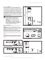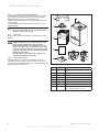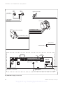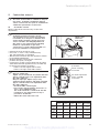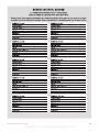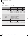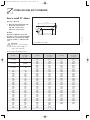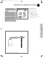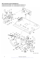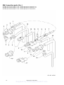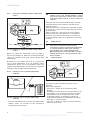
1
For the installer
Instructions for installation and servicing
ecoTEC plus
Wall hung open vent condensing boiler
GB
Supplied by HeatingSpares247.com
Contents
Contents
1
1.1
1.1.1
Page
1.4.15
1.4.16
1.4.17
1.4.18
1.4.19
1.4.20
1.4.21
1.5
1.6
1.7
1.8
1.9
Introduction . . . . . . . . . . . . . . . . . . . . . . . . . . .
Notes on the documentation . . . . . . . . . . . .
Other instructions supplied
with this appliance . . . . . . . . . . . . . . . . . . . . .
Retention of documents . . . . . . . . . . . . . . . .
Safety instructions and symbols . . . . . . . . .
ecoTEC plus boilers . . . . . . . . . . . . . . . . . . . .
General notes . . . . . . . . . . . . . . . . . . . . . . . . .
General information . . . . . . . . . . . . . . . . . . . .
Gas category . . . . . . . . . . . . . . . . . . . . . . . . . .
Gas safety (installation and use) regulations
Gas testing and certification . . . . . . . . . . . .
Control of substances hazardous to health
Insulation pads . . . . . . . . . . . . . . . . . . . . . . . .
Spare parts . . . . . . . . . . . . . . . . . . . . . . . . . . .
Manual handling guidance . . . . . . . . . . . . . . .
Gas leak or fault . . . . . . . . . . . . . . . . . . . . . . .
Clearances . . . . . . . . . . . . . . . . . . . . . . . . . . . .
Sheet metal parts. . . . . . . . . . . . . . . . . . . . . .
Sealed components . . . . . . . . . . . . . . . . . . . .
Electrical supply failure . . . . . . . . . . . . . . . . .
Protection against freezing . . . . . . . . . . . . .
Boilers installed in a compartment or
cupboard . . . . . . . . . . . . . . . . . . . . . . . . . . . . .
Boiler casing . . . . . . . . . . . . . . . . . . . . . . . . . .
Condensate drain . . . . . . . . . . . . . . . . . . . . . .
Pluming from flue terminal . . . . . . . . . . . . . .
Cleaning . . . . . . . . . . . . . . . . . . . . . . . . . . . . . .
Maintenance and servicing . . . . . . . . . . . . . .
Technical data . . . . . . . . . . . . . . . . . . . . . . . . .
Guarantee . . . . . . . . . . . . . . . . . . . . . . . . . . . .
Statutory requirements . . . . . . . . . . . . . . . . .
Regulations, rules and guidelines . . . . . . . .
CE mark . . . . . . . . . . . . . . . . . . . . . . . . . . . . . .
Benchmark. . . . . . . . . . . . . . . . . . . . . . . . . . . .
Gas council numbers . . . . . . . . . . . . . . . . . . .
2
2.1
2.1.2
2.1.3
Boiler specifications. . . . . . . . . . . . . . . . . . . .
Technical data . . . . . . . . . . . . . . . . . . . . . . . . .
Dimensions . . . . . . . . . . . . . . . . . . . . . . . . . . .
Installation . . . . . . . . . . . . . . . . . . . . . . . . . . . .
8
8
9
9
General requirements . . . . . . . . . . . . . . . . . .
Preliminary remarks for
room sealed appliances . . . . . . . . . . . . . . . . .
3.2
Related documents. . . . . . . . . . . . . . . . . . . . .
3.3
Installation site . . . . . . . . . . . . . . . . . . . . . . . .
3.4
Gas supply . . . . . . . . . . . . . . . . . . . . . . . . . . . .
3.5
Flue options. . . . . . . . . . . . . . . . . . . . . . . . . . .
3.5.1 Flue termination . . . . . . . . . . . . . . . . . . . . . . .
3.5.2 Internal flue installation . . . . . . . . . . . . . . . .
3.6
Air supply. . . . . . . . . . . . . . . . . . . . . . . . . . . . .
3.7
Cupboard or compartment ventilation . . . .
3.8
Domestic hot water cylinder. . . . . . . . . . . . .
3.9
Condensate drain . . . . . . . . . . . . . . . . . . . . . .
3.10
Heating system controls . . . . . . . . . . . . . . . .
3.11
Draining tap . . . . . . . . . . . . . . . . . . . . . . . . . . .
3.12
Safety valve . . . . . . . . . . . . . . . . . . . . . . . . . . .
3.13
Bypass . . . . . . . . . . . . . . . . . . . . . . . . . . . . . . .
3.14
Pump specification . . . . . . . . . . . . . . . . . . . . .
3.15
Cleanser and inhibitor . . . . . . . . . . . . . . . . . .
3.16
Open vented water system . . . . . . . . . . . . . .
3.17
Sealed water Systems . . . . . . . . . . . . . . . . . .
3.17.1 Safety valve . . . . . . . . . . . . . . . . . . . . . . . . . . .
3.17.2 Expansion vessel. . . . . . . . . . . . . . . . . . . . . . .
3.17.3 Pressure gauge . . . . . . . . . . . . . . . . . . . . . . . .
10
1.1.2
1.1.3
1.2
1.3
1.4
1.4.1
1.4.2
1.4.3
1.4.4
1.4.5
1.4.6
1.4.7
1.4.8
1.4.9
1.4.10
1.4.11
1.4.12
1.4.13
1.4.14
3
3.1
2
Contents
Page
4
4
3.17.4 Water make up . . . . . . . . . . . . . . . . . . . . . . . .
3.17.5 Filling a sealed water system . . . . . . . . . . . .
4
4
4
4
4
5
5
5
5
5
5
5
5
5
5
5
5
5
6
4
4.1
4.1.1
4.1.2
4.1.3
4.1.4
4.2
4.2.1
4.3
4.3.1
4.3.2
4.3.3
4.3.4
4.3.5
6
6
6
6
6
6
6
6
7
7
7
7
7
10
10
10
11
11
12
12
12
12
13
13
13
13
13
13
13
13
15
16
16
16
16
16
16
4.4.9
Boiler installation sequence . . . . . . . . . . . . .
17
17
Boiler location . . . . . . . . . . . . . . . . . . . . . . . . .
17
Sheet metal parts. . . . . . . . . . . . . . . . . . . . . .
17
Clearances . . . . . . . . . . . . . . . . . . . . . . . . . . . .
Timber frame buildings . . . . . . . . . . . . . . . . .
17
18
Contents included with delivery. . . . . . . . . .
18
Flue exit . . . . . . . . . . . . . . . . . . . . . . . . . . . . . .
Other flue options . . . . . . . . . . . . . . . . . . . . .
18
19
Fitting the boiler hanging bracket . . . . . . . .
19
Boiler fixing . . . . . . . . . . . . . . . . . . . . . . . . . . .
Removing the front casing . . . . . . . . . . . . . .
19
Gas connection . . . . . . . . . . . . . . . . . . . . . . . . 20
Water connections . . . . . . . . . . . . . . . . . . . . . 20
Condensate trap and syphonic drain . . . . .
Connection. . . . . . . . . . . . . . . . . . . . . . . . . . . . 20
Installing the flue system . . . . . . . . . . . . . . . 20
21
Electrical connections . . . . . . . . . . . . . . . . . .
Connections to main supply . . . . . . . . . . . . . 22
Wiring system . . . . . . . . . . . . . . . . . . . . . . . . . 22
Electrical board layout. . . . . . . . . . . . . . . . . . 23
Controls . . . . . . . . . . . . . . . . . . . . . . . . . . . . . . 25
External electrical controls. . . . . . . . . . . . . . 25
Connection details for external time switches
and boiler terminal strip . . . . . . . . . . . . . . . . 25
Vaillant optional plug in timer accessories. 25
Connection details using the
VR 65 control centre . . . . . . . . . . . . . . . . . . . 25
Thermostatic radiator valves . . . . . . . . . . . . 25
5
5.1
5.1.1
5.1.2
5.1.3
5.1.4
5.1.5
Commissioning (Part I) . . . . . . . . . . . . . . . . .
Preliminaries - all systems . . . . . . . . . . . . . .
Gas supply . . . . . . . . . . . . . . . . . . . . . . . . . . . .
Initial Lighting . . . . . . . . . . . . . . . . . . . . . . . . .
Ignition problems . . . . . . . . . . . . . . . . . . . . . .
Flue problems . . . . . . . . . . . . . . . . . . . . . . . . .
Testing - Gas . . . . . . . . . . . . . . . . . . . . . . . . . .
26
26
26
27
27
27
27
6
Natural Gas to LPG conversion . . . . . . . . . .
28
7
7.1
7.1.1
29
29
7.1.2
7.1.3
7.2
7.3
Functional checks commissioning (part II) .
Heating. . . . . . . . . . . . . . . . . . . . . . . . . . . . . . .
Domestic hot water . . . . . . . . . . . . . . . . . . . .
(If optional accessories are fitted). . . . . . . .
Pump exercise programme . . . . . . . . . . . . . .
Final flush of the heating system (hot) . . . .
Hand over to the user . . . . . . . . . . . . . . . . . .
Vaillant warranty. . . . . . . . . . . . . . . . . . . . . . .
29
29
30
30
30
8
8.1
8.1.1
8.1.2
8.1.3
8.1.4
8.1.5
8.1.6
8.1.7
8.1.8
8.1.9
8.1.10
8.1.11
8.1.12
Inspection and maintenance . . . . . . . . . . . . .
Initial inspection . . . . . . . . . . . . . . . . . . . . . . .
Safety instructions . . . . . . . . . . . . . . . . . . . . .
Maintenance . . . . . . . . . . . . . . . . . . . . . . . . . .
Functional check of boiler operation . . . . . .
General . . . . . . . . . . . . . . . . . . . . . . . . . . . . . . .
Spark electrode. . . . . . . . . . . . . . . . . . . . . . . .
Removing the burner . . . . . . . . . . . . . . . . . . .
Combustion chamber and heat exchanger..
Condensate drain . . . . . . . . . . . . . . . . . . . . . .
Inner casing panel seal check. . . . . . . . . . . .
Checking the expansion vessel (if fitted) . .
Re commissioning the boiler. . . . . . . . . . . . .
Test operation . . . . . . . . . . . . . . . . . . . . . . . . .
31
31
31
31
31
33
34
34
35
35
36
36
36
36
4.3.6
4.4
4.4.1
4.4.2
4.4.3
4.4.4
4.4.5
4.4.6
4.4.7
4.4.8
Installation and Servicing ecoTEC plus
Supplied by HeatingSpares247.com
Contents
Contents
Page
9
9.1
Combustion analysis . . . . . . . . . . . . . . . . . . .
Check CO2 content . . . . . . . . . . . . . . . . . . . . .
37
37
10
10.1
10.1.1
10.1.2
10.1.3
10.1.4
10.2
10.3
Trouble shooting . . . . . . . . . . . . . . . . . . . . . . .
Logical fault finding procedure. . . . . . . . . . .
Status codes . . . . . . . . . . . . . . . . . . . . . . . . . .
Diagnostic codes. . . . . . . . . . . . . . . . . . . . . . .
Fault codes. . . . . . . . . . . . . . . . . . . . . . . . . . . .
Fault memory . . . . . . . . . . . . . . . . . . . . . . . . .
Test programs . . . . . . . . . . . . . . . . . . . . . . . . .
Resetting parameter to factory settings . .
38
38
38
39
42
42
44
44
11
111.1
11.2
11.3
11.4
11.5
11.6
44
44
44
44
44
45
11.7
Parts replacement . . . . . . . . . . . . . . . . . . . . .
Safety instructions . . . . . . . . . . . . . . . . . . . . .
Replacing the burner . . . . . . . . . . . . . . . . . . .
Replacing the gas valve. . . . . . . . . . . . . . . . .
Replacing the fan . . . . . . . . . . . . . . . . . . . . . .
Replacing the heat exchanger . . . . . . . . . . .
Replacing the condense trap and siphonic
drain . . . . . . . . . . . . . . . . . . . . . . . . . . . . . . . . .
Replacing electronics and display . . . . . . . .
12
12.1
12.2
Recycling and disposal. . . . . . . . . . . . . . . . . .
Appliance . . . . . . . . . . . . . . . . . . . . . . . . . . . . .
Packaging. . . . . . . . . . . . . . . . . . . . . . . . . . . . .
46
46
46
13
Vaillant service . . . . . . . . . . . . . . . . . . . . . . . .
46
14
Appendix . . . . . . . . . . . . . . . . . . . . . . . . . . . . .
EC declaration of conformity . . . . . . . . . . . .
Benchmark gas boiler commissioning
checklist . . . . . . . . . . . . . . . . . . . . . . . . . . . . . .
Service interval record . . . . . . . . . . . . . . . . .
47
47
45
46
48
49
Installation and Servicing ecoTEC plus
Supplied by HeatingSpares247.com
3
1 Introduction
1
Introduction
1.1
Notes on the documentation.
To ensure clarity of information in instructions a
new European standard of advice and symbols is
being introduced. To ensure compliance with this
new standard the following details are included.
The following information is intended to help you
throughout the boilers entire instruction pack.
We assume no liability for any damage caused by
non-observance of these instructions.
1.1.1
Other instructions supplied with this
appliance.
For the owner:
Instructions for use no. 0020020829
Short operating instructions no. 838404
Warranty card with return envelope no. 802922
For the installer/service engineer:
Flue installation instructions no. 834449
1.2
ecoTEC plus boilers
The ecoTEC plus boilers are designed to provide
central heating from a fully pumped open-vented
or sealed water system. The central heating water
temperature can be adjusted on the boiler.
The domestic hot water can only be adjusted on the
boiler if it is installed with a Vaillant uniSTOR unvented
cylinder and relevant controls. Once the controls
are set the boiler operates automatically. A frost
protection programme is also included.
Please read these instructions and follow them
carefully for the correct and economical use of your
boiler.
These instructions are applicable to the following
ecoTEC plus boilers, available in Natural Gas.
All ecoTEC plus boilers can be converted to LPG.
APPLIANCE
MAXIMUM OUTPUT
The instructions for any accessories and controllers
used also apply.
ecoTEC plus 415
15kW
ecoTEC plus 418
18kW
The Benchmark gas boiler commissioning checklist
(in the installation manual) should be completed by the
installer and/or the commissioning engineer.
ecoTEC plus 428
28kW
ecoTEC plus 438
38kW
If, after reading these instructions, you have any
questions on the operation of the boiler, please contact
either your installer or Vaillant Technical Department.
1.1.2
Retention of documents
Please retain this literature and all related documents
so that they are available whenever they are required.
If you move please pass on the documents to the
buyer.
1.1.3
Safety instructions and symbols
Please observe the safety instructions in this literature
for the operation of the appliance.
Danger!
Immediate risk of serious injury or death!
Danger!
Risk of death from electric shock!
Danger!
Risk of burns or scalding!
Caution!
Potentially dangerous situations for the
product and environment.
Note!
Useful information and instructions.
•Symbol for a necessary task
Note!
This boiler must be installed and serviced by a
competent person in accordance with the Gas
Safety (Installation and Use) Regulations 1998.
In the UK ‘CORGI’ registered installers
undertake the work in compliance with safe
and satisfactory standard.
4
1.3
General notes
The boiler has been designed for use with a openvented central heating system, and comes fully
tested and assembled. The boiler is easily mounted
on any internal wall and can be installed with either a
horizontal or vertical RSF (room sealed fan assisted)
flue. The boiler uses a standard flue system (100 mm
or 125 mm outside diameter). Flue extensions and
additional bends and elbows are available for the
flue system to increase the flexibility. If desired, an
inhibitor may be used in the system. Guidance on the
use of inhibitors is contained in these instructions.
The boiler has a built in diagnostic system which
indicates the operational status of the boiler. This
feature provides key information to aid commissioning
and fault finding. The data badge is fitted to the
combustion chamber cover of the boiler. See text of
General Requirements for installation requirements or
notes.
The Valliant ecoTEC plus boilers have been
constructed in accordance with recognised safety
regulations. Nevertheless, danger to the life and
limb of the user or third parties can still occur or the
appliance or other material assets be damaged in the
event of improper use. The appliances are designed for
central heating systems. Any other use or extended
use is considered to be use other than intended. The
manufacturer/supplier is not liable for any resulting
damage. Intended use includes the observance of the
operating and installation manual and the adherence
to the inspection and maintenance conditions.
Caution!
Any incorrect use is forbidden.
The appliances must be installed by a competent
person, who is responsible for adhering to the existing
regulations, rules and guidelines.
Installation and Servicing ecoTEC plus
Supplied by HeatingSpares247.com
Introduction 1
1.4
General information
Thank you for choosing a Vaillant boiler. The
information given in this booklet will enable you to
obtain the best performance from your boiler.
The Benchmark logbook should be completed by the
installer and/or commissioning engineer and handed to
the user.
1.4.1
Gas category
The boiler is supplied factory set for use on Natural
Gas (G20). The ecoTEC plus boilers can be field
adjusted for use on LPG (propane G31), see section
7 for instructions or contact Vaillant Service, 0870
6060 777.
1.4.2
Gas safety (installation and use) regulations
In your own interests and that of safety, it is the Law
that ALL gas appliances are installed by a competent
person in accordance with the current issue of the
above regulations.
1.4.3
Gas testing and certification
The boiler is tested and certificated for safety and
performance. It is, therefore, important that no
alteration is made to the boiler.
1.4 4 Control of substances hazardous to health
Under Section 6 of The Health and Safety at Work Act
1974, we are required to provide information on
substances hazardous to health.
The adhesives and sealants used in this appliance are
cured and give no known hazard in this state.
1.4.5
Insulation pads
These can cause irritation to skin, eyes and the
respiratory tract.
If you have a history of skin complaint you may be
susceptible to irritation. High dust levels are usual only
if the material is broken.
Normal handling should not cause discomfort, but
follow normal good hygiene and wash your hands
before eating, drinking or going to the lavatory.
If you do suffer irritation to the eyes or severe
irritation to the skin seek medical attention.
1.4.6
Spare parts
Only original Vaillant spare parts may be used.
1.4.7
Manual handling guidance
During the appliance installation and the replacement
of the heat exchanger it will be necessary to employ
caution and assistance whilst lifting as the appliance
or component exceeds the recommended weight for a
one man lift.
In certain situations it may be required to use a
mechanical handling aid.
Take care to avoid trip hazards, slippery or wet
surfaces.
Danger
Smell of gas. Risk of poisoning and explosion
due to a malfunction
1.4.8 Gas leak or fault
If you smell gas or suspect a gas leak:
• Do not switch lights on or off.
• Do not use any other electrical switches.
• Do not use a telephone in the hazardous area.
• Do not use naked flames, such as matches or
cigarette lighters.
• Do not smoke.
• Turn off the gas supply at the gas meter.
• Open the windows and doors.
• Warn other residents.
• Get out of the house.
• Consult your gas supplier, service agent or other
competent person.
1.4.9
Clearances
If fixtures are positioned close to the boiler, space
must be left as shown in fig 4.1. Enough space must
also be left in front of the boiler to allow for servicing.
1.4.10 Sheet metal parts
This boiler contains metal parts (components) and care
should be taken when handling and cleaning, with
particular regard to edges.
1.4.11 Sealed components
Under no circumstances must the User interfere with
any sealed component as this could result in a
potentially dangerous situation arising.
Danger
This boiler must be earthed.
1.4.12 Electrical supply failure
The boiler will not work without an electrical supply.
Normal operation of the boiler should resume when
the electrical supply is restored.
Reset any external controls to resume normal
operation of the central heating.
If the boiler does not resume normal operation.
(The burner fails to ignite after five attempts).
The overheat thermostat may have operated.
Automatic ignition can only take place after you
manually reset the fault, refer to section 5.1.3. to reset.
Installation and Servicing ecoTEC plus
Supplied by HeatingSpares247.com
5
1 Introduction
1.4.13 Protection against freezing
The boiler has a built in frost protection programme as
long as the electricity and gas are left switched on.
This device operates the burner and system pump
when the temperature inside the boiler falls to 3°C.
Any other exposed areas of the system should be
protected by a separate frost thermostat.
If the mains electricity and gas are to be turned off for
any long periods during severe weather, it is
recommended that the whole system, including the
boiler, should be drained to avoid the risk of freezing.
Make sure that, if fitted, the immersion heater in the
cylinder is switched off.
If you have a sealed water system contact your
installation/ servicing company as draining, refilling
and pressurising MUST be carried out by a competent
person.
As a safety feature the boiler will stop working if the
condensate drain becomes blocked. During freezing
conditions this may be due to the forming of ice in the
condense drain external to the house. Release an ice
blockage by the use of warm cloths on the pipe. The
boiler should then restart. Contact your installation/
servicing company if the fault persists.
1.4.19 Maintenance and servicing
For the continued efficient and safe operation of the
boiler it is recommended that it is checked and
serviced at regular intervals. The frequency of
servicing will depend upon the installation conditions
and usage, but in general, once a year should be
enough.
If this appliance is installed in a rented property there
is a duty of care imposed on the owner of the property
by the current issue of the Gas Safety (Installation and
Use) Regulations, Section 35.
Servicing/maintenance should be carried out by a
competent person in accordance with the rules in force
in the countries of destination.
To obtain service, please call your installer or Vaillant
Service Solutions (0870 6060 777).
Please be advised that the installation engineer on
completion of commissioning and servicing should
complete the ‘Benchmark’ logbook.
All CORGI Registered Installers carry a CORGI ID
card, and have a registration number. Both should be
recorded in your boiler Logbook. You can check your
installer is CORGI registered by calling CORGI direct
on: - 01256 372300.
1.4.14
1.4.20 Technical data
Al dimensions are given in millimetres (except as
noted). The data label is positioned on the combustion
chamber cover. The Seasonal Efficiency Domestic
Boilers UK (SEDBUK) is:
All ecoTEC plus boilers : Class ‘A’.
The value is used in the UK Government’s Standard
Assessment Procedure (SAP) for energy rating of
dwellings. The test data from which it has been
calculated has been certified by B.S.I.
Boilers installed in a compartment or
cupboard
If the boiler is fitted into a compartment or cupboard it
does not require ventilation openings.
Do not use the compartment or cupboard for storage.
1.4.15 Boiler casing
Do not remove or adjust the casing in any way, as
incorrect-fitting may result in incorrect operation or
failure to operate at all.
1.4.16 Condensate drain
The condensate drain must not be modified or blocked.
1.4 .17 Pluming from flue terminal
All condensing boilers produce a plume of water
vapour from the flue terminal. This is due to the
high efficiency and hence low flue gas temperature.
This may increase in wet, damp weather but this is
completely normal and indicates that the boiler is
operating correctly.
1.4.18 Cleaning
This appliance contains metal parts and care should
be taken when handling and cleaning with particular
regard to edges.
The boiler casing can be cleaned using a mild liquid
detergent with a damp cloth, then a dry cloth to polish.
Do not use any form of abrasive or solvent cleaner as
you may damage the paint work.
6
1.4.21 Guarantee
Vaillant provide a full two year parts and labour
warranty for your appliance.
The appliance must be installed by a suitably
competent person in accordance with the gas
safety (installation and Use) Regulations 1998, and
the manufacture's instructions. In the UK ‘CORGI’
registered installers undertake the work in compliance
with safe and satisfactory standards.
Terms and conditions apply to the warranty, details of
which can be found on the warranty registration card
included with this appliance.
Failure to install and commission this appliance in
compliance with the manufacture's instructions may
invalidate the warranty (this does not affect your
statutory rights).
Installation and Servicing ecoTEC plus
Supplied by HeatingSpares247.com
Introduction 1
1.5
Statutory requirements
The appliance is suitable only for installation in GB and
IE and should be installed in accordance with the rules
in force. In GB the installation of the boiler must be
carried out by a competent person as described in the
following regulations:
The manufacturer’s instructions supplied.
The Gas Safety (Installation and Use) Regulations.
The appropriate Buildings Regulations either The
Building Regulations, The Building Regulations
(Scotland), The Building Regulations (Northern
Ireland).
The Water Fittings Regulations or Water bye laws in
Scotland. The Health and Safety at Work Act, Control
of Substances Hazardous to Health (COSHH).
The Current I.E.E. Wiring Regulations.
Where no specific instructions are given, reference
should be made to the relevant British Standard Code
of Practice. In IE, the installation must be carried out
by a competent person and installed in accordance
with the current edition of I.S.813 “Domestic Gas
Installations”, the current Building Regulations and
reference should be made to the current ETCI rules for
Electrical Installation.
In GB the following Codes of Practice apply:
BS4814, BS6798, BS5440 Part 1 and 2, BS5546 Part
1, BS5449, BS6891, BS6700, BS7074 Part 1 and 2,
BS7593, BS7671.
In IE: I.S.813, BS5546, BS 5449, BS 7074, BS 7593.
Manufacturer’s instructions must not be taken as
overriding statutory requirements.
Note: For further information, see the current issue of
the
Building Regulations, approved document L1 ( in the
UK) and the current issue of the following:
1) Central heating system specification (CheSS)
2) Controls for domestic central heating system and
hot water. BRECSU.
Certification
This boiler certificated to the current issue of EN 483
for performance and safety.
It is important that no alteration is made to the boiler,
without permission, in writing, from Vaillant.
Any alteration that is not approved by Vaillant, could
invalidate the warranty and could also infringe the
current issue of the Statutory Requirements.
1.6
Regulations, rules and guidelines.
This boiler meets the requirements of Statutory
Instrument, No. 3083 The Boiler (Efficiency)
Regulations, and therefore is deemed to meet the
requirements of Directive 92/42/EEC on the efficiency
requirements for new hot water boilers fired with liquid
or gaseous fuels.
Type test for purposes of Regulation 5 certified by:
Notified body 0087.
Product/production certified by: Notified body 0086.
1.7
CE mark
The CE mark on this appliance shows compliance with:
- Directive 90/396/EEC on the approximation of the
laws of the Member States relating to appliances
burning gaseous fuels.
- Directive 73/23/EEC on the harmonisation of the
Laws of the Member States relating to electrical
equipment designed for use within certain voltage
limits.
- Directive 89/336/EEC on the approximation of the
Laws of the Member States relating to
electromagnetic compatibility.
1.8
Benchmark
Vaillant Ltd. support the Benchmark initiative.
At the rear of the installation manual, you will
find a Benchmark gas boiler commissioning
checklist. It is very important that this is
completed correctly at the time of installation,
commissioning and hand over to the user.
1.9
Gas council numbers
Appliance
ecoTEC plus 415
ecoTEC plus 418
ecoTEC plus 428
ecoTEC plus 438
Installation and Servicing ecoTEC plus
Supplied by HeatingSpares247.com
Gas council numbers
41-044-53
41-044-54
41-044-55
41-044-57
7
2 Boiler specifications
2 Boiler specifications
2.1
Technical data
Description
Unit
ecoTEC plus 415
ecoTEC plus 418
ecoTEC plus 428
ecoTEC plus 438
Maximum CH heat input (net)
kW
15.3
18.9
28.6
38.4
CH heat output (80/60 °C)
kW
5.0 - 15.0
5.0 - 18.6
5.3 - 28.2
6.3 - 38.0
CH heat output (50/30 °C)
kW
5.3 - 16.2
5.3 - 20.0
5.7 - 30.6
6.8 - 41.0
A
A
A
A
90.5
90.4
90.6
90.8
NOx Class
5
5
5
5
"lP rating"
IPX4D
IPX4D
IPX4D
IPX4D
mbar
20
20
20
20
MJ/
37.8
37.8
37.8
37.8
SEDBUK Band
SAP Seasonal Efficiency
%
Inlet gas working pressure
required (natural gas)
Gas supply (G20) Gross CV (s.t.)
m3
Maximum gas rate
M3/h
1.61
2.0
3.02
4.06
Minimum gas rate
M3/h
0.53
0.53
0.56
0.71
Burner % CO2 (Case on)
%
9.3 + 0.2 - 0.5
9.3 + 0.2 - 0.5
9.3 + 0.2 - 0.5
9.0 + 0.2 - 0.5
Gas connection (compression)
mm
15
15
15
15
Water connections (compression)
mm
22
22
22
22
Condensate drain (internal
mm
19 min.
19 min.
19 min.
19 min.
Fuse ratings fan supply PCB
A
3.15 AT
3.15 AT
3.15 AT
3.15 AT
Main PCB
A
125 mAT
125 mAT
125 mAT
125 mAT
Minimum flow rate of water
L/min.
10.8
12.9
20.3
27.2
Weight
kg
3.1
3.1
3.3
3.3
Electrical supply
V~/
230/~50
230/~50
230/~50
230/~50
diameter)
through the boiler
HZ
External fuse
A
3
3
3
3
Power input
W
60
60
60
60
Case height
mm
600
600
600
600
Case width
mm
375
375
375
375
Case depth
mm
334
334
334
334
8
Installation and Servicing ecoTEC plus
Supplied by HeatingSpares247.com
Boiler specifications 2
Dimensions
FLUE
CL
5
26
160
1
6
48
33
FLUE
CL
2
4
FLUE
CL
OUTSIDE
WALL
FACE
176
FLUE
C
161 L
113
53
340
2.1.2
610
BOILER
CL
BOILER
CL
Fig. 2.1 Dimensions in mm
30
133
56
3
15mm GAS
CONNECTION
7
375
2.1.3
Installation
Legend:
1 Heating return pipe Ø 22
2 Heating flow pipe Ø 22
3 Gas connection Ø 15
4 Hanging bracket
5 Flue hole - flue system 303 933
6 Flue pipe connection
7 Condensate drain outlet connection (Ø 21)
1
5
6
2
7
3
4
Fig. 2.2 Function elements of boiler
Legend:
1 Flue pipe connection
2 Fan
3 Gas valve
4 Electronics box
5 Burner module
6 Ignition electrode
7 Condense trap
Installation and Servicing ecoTEC plus
Supplied by HeatingSpares247.com
9
3 General requirements
3
General requirements
3.1
Preliminary remarks for room sealed
appliances
This appliance should only be installed with a Vaillant
flue system.
Install the flue system as detailed in the separate flue
installation instructions supplied with this boiler.
3.2
Related documents
The installation of the boiler must be in accordance
with the relevant requirements of Gas Safety
(Installation and Use) Regulations 1998, Health and
Safety Document No. 635 (The Electricity at Work
Regulations 1989), BS7671 (IEE Wiring Regulations)
and the Water Supply (Water Fitting) Regulations 1999,
or The Water Bylaws 2000 (Scotland). It should also
be in accordance with the relevant requirements of
the Local Authority, Building Regulations, The Building
Regulations (Scotland), The Building Regulations
(Northern Ireland) and the relevant recommendations
of the following British Standards: BS 6700: Services
supplying water for domestic use within buildings and
their curtilages. BS 6798: Specification for installation
of gas fired boilers not exceeding 60 kW input.
BS 6891: Specification for installation of low pressure
gas pipe work up to 28 mm (R1) in domestic premises
(2nd family gas). BS 7593: Treatment of water in
domestic hot water central heating systems. Institute
of Gas Engineers Publication IGE/UP/7/1998: ”Guide
for gas installations in timber framed housing”.
IGE/UP1: Soundness testing and purging of industrial
and commercial gas installation. IGE/UP2: Gas
installation pipe work, boosters and compressors
on industrial and commercial premises. IGE/UP10.
Installation of gas appliances in industrial and
commercial premises. BS. 6644: Installation of gas
fired hot water boilers of rated inputs between 60
kW and 2 MW (2nd and 3rd family gases). BS. 5449:
Forced circulation hot water central heating systems
for domestic premises. Note: only up to 45 kW.BS.
6880: Low temperature hot water heating systems of
output greater than 45 kW.
Part 1 Fundamental and design considerations.
Part 2 Selection of equipment.
Part 3 Installation, commissioning and maintenance.
BS. 4814: Specification for: Expansion vessels using an
internal diaphragm, for sealed hot water heating
systems. BS. 5440: Installation and maintenance of
flues and ventilation for gas appliances of rated input
not exceeding 70 kW net (1st, 2nd and 3rd family
gases).
Part 1 Specification for installation of flues.
Part 2 Specification for installation and maintenance
of ventilation for gas appliances. European installation
directive
Caution!
The appliance must be installed and serviced
by a competent person as stated in the Gas
Safety (Installation and Use) Regulations 1998.
In IE, the installation must be in accordance
with the current edition of I.S.813
‘Domestic Gas Installations’, the current
Building Regulations and reference should be
made to the current ETCI rules for electrical
installation.
10
Caution!
When tightening or slackening screwed
connections always use suitable open-ended
spanners (not pipe wrench, or extensions, etc.).
Incorrect use and/or unsuitable tools can lead
to damage being caused (e.g. gas or water
leakage)!
3.3
Installation site
The location chosen for the boiler must permit
the provision of a satisfactory flue termination.
The location must also provide adequate space
for servicing and air circulation around the boiler.
The boiler may be installed in any room, although
particular attention is drawn to the requirements of
BS 7671 (IEE Regulations), the electrical provisions of
the Building Standards (Scotland) Regulations, and in
IE the current edition of IS 813 and the current ETCI
rules, in respect of the installation of a boiler in a room
containing a bath or shower.
Note!
If a room sealed boiler is installed in a room
with a bath or shower, electrical switches or
boiler controls using the mains power supply
must be placed at locations that cannot be
reached by the person in the bath or shower.
If the boiler is installed in an unusual location, special
procedures may be necessary and BS 5546 and BS
6798 give detailed guidance on this aspect. The boiler
must be mounted on a flat, vertical wall, which must be
sufficiently robust to take the weight of the boiler. The
boiler may be installed on a combustible wall, subject
to the requirements of the Local Authorities and
Building Regulations.
A compartment used to enclose the boiler must be
designed and constructed specifically for this purpose.
(An existing cupboard or compartment may be used
provided that it is modified for the purpose). Details
of essential features of cupboard/compartment design
including airing cupboard installations are given in BS
6798. If the boiler is to be fitted in a timber framed
building, it should be fitted in accordance with Institute
of Gas Engineers Publication IGE/UP/7/1998 “Guide
for Gas Installation in Timber Framed Housing”. Please
note the safety instructions below before deciding
where to install the boiler:
Caution
Do not !install the appliance in rooms prone
to frost. In rooms with aggressive steam
or dust, the appliance must be operated
independent of the ambient air.
When choosing the place of installation and while
operating the appliance, make sure that the air
supply is free of chemical substances containing
fluorine, chlorine, sulphur etc. Sprays, solvents and
cleaning agents, paints, adhesives etc. contain the
kind of substances that can lead to corrosion even in
the exhaust system when the appliance is operated
depending on the ambient air in the worst case
scenario. Particularly in hair-cutting salons, lacquering
and finishing, cleaning facilities, the appliance must be
operated independent of the ambient air! Otherwise,
a separate installation room is required to guarantee
that the air supply is free of the above mentioned
substances.
Installation and Servicing ecoTEC plus
Supplied by HeatingSpares247.com
General requirements 3
1435
10
550
3.4
Gas supply
The gas supplier should ensure the availability of an
adequate supply of gas. A gas meter may only be
connected to the service pipe by the supplier of gas or
their contractor. An existing meter should be checked
to ensure that it is capable of passing the rate of gas
supply required. Installation pipes should be fitted in
accordance with BS 6891. In IE the current edition of
IS 813. Pipe work from the meter to the boiler must be
of an adequate size. Do not use pipes of a smaller size
than the boiler gas connection (15 mm). The complete
installation must be checked for leaks and purged as
described in BS 6891.
3.5
Flue options
There are various flue systems to choose from, as
follows:
60/100 standard horizontal air/flue duct, see fig 3.1.
60/100 telescopic horizontal air/flue duct, see fig 3.2.
60/100 Vertical air/flue duct and terminal, see fig 3.3.
80/125 horizontal air/flue duct, see fig 3.4.
80/125 Vertical air/flue duct and terminal, see fig 3.5.
Flue extensions are available to extend the length,
both 90° bends and 45° elbows are also available.
40
880
Danger!
Vaillant appliances are certified only for
use with genuine Vaillant flue pipes.
Only use genuine Vaillant flue pipes.
Malfunctions can occur if you use other
accessories.
These may result in damage and injury.
You will find a list of genuine flue pipes in the
Vaillant installation manual for flue pipes.
The CE mark is valid only if the appliance is
operated with Vaillant flue pipes.
Fig. 3.3 Art. No. 303900
110 3
Refer to flue system installation instructions for full
details.
70
15
70
When extension pipes are used the flue system must
be designed to have a continuous fall to the boiler
of at least 3° to allow condensate to run out via the
drain.
Fig. 3.4 Art. No. 303209
754
87
48
30
650
74
65
30
13
48
70
65
880
405 - 610
1530
Fig. 3.1 Art. No. 303933
Fig. 3.2 Art. No. 303936
Fig. 3.5 Vertical Flue System Art. No. 303200
Installation and Servicing ecoTEC plus
Supplied by HeatingSpares247.com
11
3 General requirements
3.5.1
Flue termination
The following details refer to both flue systems.
a. The terminal must be located where the combustible
substances can escape freely at all times.
b. A plume of water vapour will sometimes be visible
from the flue terminal. Positions where this could be
a nuisance should be avoided.
c. If the terminal is fitted less than 2 m above a balcony,
above ground or above a flat roof to which people
have access then a suitable terminal guard must be
provided and fitted (made by Tower Flue Components,
Tonbridge, TN9 1TB, Model K3, plastic coated).
Note!
In addition, the terminal should not be nearer
than 150 mm to an opening in the building
fabric formed for the purpose of
accommodating a built-in element such as a
window.
BS 5440–1: It is recommended that the fanned flue
terminal should be positioned as follows:
a) at least 2 m from an opening in the building directly
opposite, and
b) so that the products of combustion are not directed
to discharge across a boundary.
1) Dimensions B, C and D: These clearances may be
reduced to 25 mm without affecting the
performance of the boiler. In order to ensure
that the condensate plume does not affect adjacent
surfaces the terminal should be extended as shown
in Fig. 3.7.
2) Dimension F:
This clearance may be reduced to 25 mm without
affecting the performance of the boiler. However,
in order to ensure that the condensate plume does
not affect adjacent surfaces a clearance of 300 mm
is preferred. For IE, recommendations are given in
the current edition of IS 813.
Fig. 3.6 Flue termination
Note!
Vertical flues must not terminate within
600mm of an openable window, air vent or
any other ventilation opening.
The flue assembly shall be so placed or shielded as to
prevent ignition or damage to any part of the building.
Terminal position
mm
A
Directly below an opening, above an opening or
horizontal to an opening, air brick, opening window,
etc.
300
B
Below gutters, soil pipes or drain pipes
75
C
Below eaves
200
D
Below balconies
200
E
From vertical drain pipes and soil pipes
25
F
From internal or external corners
300
G
Above ground, roof or balcony
300
H
From a surface facing a terminal
600
I
From a terminal facing a terminal
1200
J
From an opening in the car port (e.g. door, window)
into the dwelling
1200
K
Vertically from a terminal on the same wall
1500
L
Horizontally from a terminal on the same wall
300
M
Distance from adjacent wall for vertical Flue
500
Fig. 3.7 Flue termination under balcony/eves
3.5.2 Internal flue installation
The flue can be installed from inside the building when
access to the outside wall face is not practicable.
3.6
Air supply
Detailed recommendations for air supply are given in
BS 5440: Part 2.
It is not necessary to have an air vent in the room or
internal space in which the boiler is installed.
3.7
Cupboard or compartment ventilation
The boilers are very high efficiency appliances.
As a consequence the heat loss from the appliance
casing during operation is very low. For cupboard or
compartment installations it is therefore not necessary
to provide any high or low level permanent air vents
for cooling purposes.
Table 3.1 Flue terminal position for a fan assisted
concentric flue
12
Installation and Servicing ecoTEC plus
Supplied by HeatingSpares247.com
General requirements 3
3.8
Domestic hot water cylinder
Caution!
Single feed indirect cylinders are not suitable.
The domestic hot water cylinder must be of
the double feed fully indirect coil type. It must
be suitable for working at a gauge pressure of
0.35 bar above the safety valve setting.
Unvented hot water cylinder
3.8.1
The ecoTEC plus can be connected to an unvented
hot water cylinder. Vaillant offer a range of cylinders
called uniSTOR with capacities from 125 litres to 310
litres. All unvented domestic hot water cylinders must
be installed by a competent person to the current
building regulations and water regulations at the time
of installation.
For building regulations refer to G3 and for water
regulations guidance G17 to G24 and recommendation
R17 to R24.
For Ireland: The current issue of BS5546 and BS6700.
If fitting to an existing system the local authority
should be informed.
3.9
Condensate drain
A plastic drain pipe must be fitted to allow discharge
of condensate to a drain.
Condensate should, if possible, be discharged into the
internal household draining system. If this is not
practical, discharge can be made externally into the
household drainage system or a purpose designed soak
away, see Section 4.3.5 for more details.
3.10
Heating system controls
It is recommended that a programmer and room
thermostat control the boiler. Vaillant have a range of
optional easy fit controls available.
Thermostatic radiator valves must be installed,
however they must not be fitted in a room where the
room thermostat is located.
Note!
All systems must have at least one radiator
not fitted with a thermostatic valve.
Note!
For further information, see the current issue
of the Building Regulations, approved
document L1, and the following current
issues of:
1) Central heating system specification (CheSS)
and
2) Controls for domestic central heating
system and hot water. BRECSU.
3.11
Draining tap
A draining tap must be provided at all the lowest
points of the system, which will allow the entire system
and hot water system to be drained.
Draining taps shall be to the current issue of BS 2879.
3.12
Safety valve
A safety valve need not be fitted to an open-vented
system.
3.13
Bypass
A system bypass will be required fitted at least 1.5
metres away from the boiler, refer to the current issue
of central heating system specifications (CHeSS).
3.14
Pump specification
The pump should be fitted on the flow pipe from the
boiler and have isolating valves each side.
A variable duty pump should be set to give a
temperature difference of no greater than 20°C
Cleanser and inhibitor
3.15
In the case of an existing installation, it is ESSENTIAL
that prior to installing the new boiler the system
is thoroughly flushed. For optimum performance
after installation of a new system, the boiler and its
associated central heating system should also be
flushed. Flushing should be carried out in accordance
with BS7593: 1992 using a cleanser such as Sentinel
X300 or X400, or Fernox Superfloc.
For long-term corrosion protection, after flushing, an
inhibitor suitable for stainless steel heat exchangers
should be used, refer to the current issue of BS 5449
and BS 7593 on the use of inhibitors in central heating
systems. Examples are Sentinel X100 and Fernox.
Caution!
It is ESSENTIAL that the cleanser is fully
removed from the system after flushing and
before adding inhibitor. Take care to ensure
that all low points in the system are fully
drained.
For all systems follow the manufacture’s instructions,
but where new radiators are fitted do not leave the
cleanser in the system for longer than 24 hours.
For optimum performance the boiler and its
associated central heating system should be flushed in
accordance with BS7593: 1992 using a cleanser.
For optimum performance the boiler and its
associated central heating system should be flushed in
accordance with BS7593: 1992 using a cleanser.
For advice on the application of system cleansers and
inhibitors contact either;
Fernox, Alpha-Fry Technologies
Tandem House
Marlow Way
Beddington Farm Road
Croydon CR0 4XS
Tel: 0870 601 5000
Fernox technical help line
01799 550811
or:
Sentinel, GE Betz
Widnes
Cheshire, WA8 8UD
Tel: 0151 420 9595.
Installation and Servicing ecoTEC plus
Supplied by HeatingSpares247.com
13
3 General requirements
ecoTEC plus 415 pressure loss graph
ecoTEC plus 428 pressure loss graph
ecoTEC plus 418 pressure loss graph
ecoTEC plus 438 pressure loss graph
Fig. 3.8 Pressure loss
14
Installation and Servicing ecoTEC plus
Supplied by HeatingSpares247.com
General requirements 3
3.16
Open vented heating system
The boiler must be supplied from an unrestricted
water supply taken from a feed and expansion cistern
situated at a maximum height of 27 metres (90ft)
above the boiler.
The cold feed must be 15mm minimum size.
The vent must rise continuously and be unrestricted.
It is important that the relative positions of the pump,
cold feed and open vent are as shown in fig 3.9.
Fig. 3.9 Open vented system
Installation and Servicing ecoTEC plus
Supplied by HeatingSpares247.com
15
3 General requirements
3.17
Sealed water systems
The installation must comply with the appropriate
requirements of the current issue of BS4814, BS5449,
BS6759, BS6798 and BS7074 Part 1 and 2. For IE your
attention is drawn to the current edition of IS 813.
See fig 3.10 for a suggested layout.
3.17.1 Safety valve
A safety valve must be fitted to a sealed system.
It shall be preset, non-adjustable with a lift pressure
of 3-bar, incorporating seating of a resilient material, a
test device and a connection for drain.
The safety valve discharge pipe must be routed to
outside the building, must not discharge above an
entrance or window or any type of public access area,
be clear of any electrical fittings and positioned so
that any discharge can be seen.
3.17.2 Expansion vessel
A diaphragm type expansion vessel, conforming to
the current issue of BS4814 (see also BS7074 Part
1 and 2). For IE the current edition of IS 813, must
be connected at a point close to the inlet side of the
circulating pump, see the Typical installation, Fig. 3.10.
unless laid down differently by the manufacturer.
The expansion vessel volume depends on the total
water system volume and the initial system design
pressure. For any system an accurate calculation of
vessel size is given in the current issue of BS5449 and
BS7074 Part 1.
Example: For an initial design pressure of 0.7 bar, the
minimum total vessel volume required is 0.063 x Total
System Volume.
Note!
A higher initial design pressure requires a
larger volume expansion vessel.
The charge pressure must not be less than the
static head of the system, that is, the height of the
highest point of the system above the expansion
vessel.
3.17.3 Pressure gauge
A pressure gauge with a set pointer and covering
at least 0 to 4 bar (0 to 60 lb/in2) shall be fitted
permanently to the system in a position where it can
be seen when filling the system.
3.17.4 Water make up
Provision should be made for replacing water loss
from the system using a make up bottle mounted in
a position higher than the top point of the system,
connected through a non-return valve to the return
side of either the heating circuit or the hot water
cylinder.
Alternatively, provision for make up water should be
made using a proprietary filling loop.
3.17.5 Filling a sealed water system
Provision for filling the system at low level must be
made. This can be achieved by the use of a proprietary
filling loop.
Fig. 3.10 Typical installation
16
Installation and Servicing ecoTEC plus
Supplied by HeatingSpares247.com
Boiler installation sequence 4
4
4.1
Boiler installation sequence
Boiler location
Note!
This boiler is not suitable for outdoor
installation.
This boiler may be installed in any room,
although particular attention is drawn to the
installation of a boiler in a room containing a
bath or shower where reference must be made
to the relevant requirements.
This boiler is suitable for installation in
bathroom zones 2 and 3.
4.1.1
5
5
600
Sheet metal parts
Caution!
When installing the appliance, care should be
taken to avoid any possibility of personal injury
when handling sheet metal parts.
In GB this is the current I.E.E. WIRING REGULATIONS
and BUILDING REGULATIONS. In IE reference should
be made to the current edition of I.S.813 “Domestic
Gas Installations” and the current ETCI rules. The
boiler must be mounted on a flat wall, which is
sufficiently robust to take its total weight, see boiler
specifications 2.1.
4.1.2
Clearances
The boiler should be positioned so that at least the
minimum operational and servicing clearances are
provided, see fig 4.1.
Additional clearances may be beneficial around the
boiler for installation and servicing.
For flue installations where external access is not
practicable, consideration should be given for the
space required to insert the flue internally, which may
necessitate clearance larger than those specified in fig
4.1.
4.1.3
Timber frame buildings
If the boiler is to be installed in a timber frame building
it should be fitted in accordance with the Institute of
Gas Engineers document IGE/UP/7/1998. If in doubt
seek advice from the local gas undertaking or Vaillant.
*
150
5
5
5
200
*A removable compartment door can be
placed at least 5mm in front of the appliance
MINIMUM CLEARANCES FROM
PERMANENT SURFACES
Fig. 4.1 Distance during installation
Installation and Servicing ecoTEC plus
Supplied by HeatingSpares247.com
17
4 Boiler installation sequence
4.1.4
Contents included with delivery
The Vaillant ecoTEC plus is delivered pre-mounted in
a package unit. Check that all the parts have been
delivered intact (see fig. 4.2 and table 4.1.
DO NOT remove the boiler from the polystyrene base
at this stage.
Place aside the flue adaptor and connections pack
until required.
2
1
3
Note
Care should be taken not to scratch the white
surface of the boiler casing.
4 .2
Flue exit
Refer to flue system installation instructions for full
details.
4
Danger!
Vaillant appliances are certified only for use
with genuine Vaillant flue pipes. Only use
genuine Vaillant flue pipes. Malfunctions can
occur if you use other accessories. These may
result in damage and injury. You will find a list
of genuine flue pipes in the Vaillant installation
manual for flue pipes.
The CE mark is valid only if the appliance is
operated with Vaillant flue pipes.
4.2.1
Other flue options
Flue instructions for other flue systems such as
vertical RSF flues, flues run to the side of the boiler
and the use of additional bends etc. are detailed in the
flue installation instructions.
5
7
8
6
Fig. 4.2
Contents included with delivery
Item
Quantity
Description
1
1
Boiler
2
1
Hanging bracket
3
1
Flue connection adaptor
4
1
Instruction booklets
5
2
Guarantee card, envelope and log book
6
1
Template
7
1
Screws/wallplugs
8
1
Gas service valve, compression couplers
and condense drain pipe coupler
Table 4.1 Contents included with delivery
18
Installation and Servicing ecoTEC plus
Supplied by HeatingSpares247.com
Boiler installation sequence 4
4.3
Fitting the boiler hanging bracket
Reposition the wall template over the flue hole
ensuring the template is vertical and mark the position
of the fixing holes for the hanging bracket, see fig 4.3.
Mark and drill the fixing holes and secure the hanging
bracket. Fix the hanging bracket to the wall using
the screws supplied. Ensure the uppermost set of
screw positions are used (it may be necessary to use
additional or alternative fixings to ensure adequate
support).
160
Note!
If the boiler is to be fitted in a timber framed
building ensure that the bracket is secured to a
substantial part of the timber frame capable of
taking the weight of the boiler.
4.3.1
Boiler fixing
Lift the boiler into position in the following manner:
Lean the top of the boiler slightly to the wall and
position just above the hanging bracket. Allow the
boiler to slowly move downwards until engaged in the
hanging bracket.
4.3.2 Removing the front casing
Remove the front casing securing screws then lift the
case upwards off the two top retaining dowels, see fig
4.4.
Fig. 4.3 Boiler hanging bracket
RETAINING
DOWEL (2 OFF)
Note!
Take care not to damage the front casing.
FRONT
CASING
SCREW (2 OFF)
Fig. 4.4 Removing front casing
Installation and Servicing ecoTEC plus
Supplied by HeatingSpares247.com
19
4 Boiler installation sequence
4.3.3
Gas connection
Danger!
The gas connection may only be made by a
competent person.
The legal directives and the local regulations
for gas supply companies must be observed.
Caution!
Ensure a stress-relief assembly of the gas
pipes to avoid leakages!
Caution!
The gas regulating block may be tested for
leakage only with a maximum pressure of
150 mbar!
Higher testing pressures can damage the
gas fitting.
Caution!
When making final connection to the boiler, if
using soldered fittings, extra care should be
taken to avoid damage to isolation valves
through heat transfer.
Before connection check the supply of
local gas.
Note!
Ensure the gas supply pipe work is adequately
sized so that a 20 mbar gas pressure is
available at the boiler inlet at full flow rate.
• Tighten all connections.
• Check the gas connection with leak indicator
spray for leakage.
The gas supply can be connected from below, or
through the wall at the rear of the boiler. See fig 4.5.
and refer to section 3.4.
The whole of the gas installation, including the meter,
should be inspected, tested for soundness and purged
in accordance with the current issue of BS6891 and
in IE the current edition of I.S.813 “Domestic Gas
Installations”.
4.3.4
Water connections
Caution!
When making final connection to the boiler, if
using soldered fittings, extra care should be
taken to avoid damage through heat transfer.
of a least (45mm per metre) away from the boiler.
Condensate should, if possible be discharged into the
household internal drainage system.
The condensate is discharged periodically in ‘slugs’ by
siphonic action.
It is not necessary to provide air breaks or extra traps
in the discharge pipe as there is already a 75mm high
trap inside the boiler. Fitting an extra trap may cause
the boiler siphon to work incorrectly.
Refer to BS5546 or BS6798 for advice on disposal of
boiler condensate.
(a) Preferably the drain pipe should run and terminate
internally to the house soil and vent stack at least
450mm above the invert of the stack. There must be
an air break in the discharge pipe upstream of the trap.
This should be designed so that the condensate cannot
be discharged into the house if the condensate drain
pipe becomes blocked.
(b) Connecting into the internal discharge branch
(e.g. sink waste or washing machine) with an external
termination, the condensate drain pipe should have a
minimum diameter of 22mm with no length restriction
and should incorporate a trap with a 75mm (3)
seal. The connection should preferably made down
stream of the sink waste trap, if the connection is
only possible up stream, then an air break is needed
between the two traps. This is normally provided by
the sink waste.
(c) Termination in a gully (5) below grid level (6) and
above the water level. The external pipe length should
be kept as short as possible to minimise the risk of
freezing and should not be more than 3 metres.
(d) At a condensate absorption point (soak away) (7).
The external pipe length should not be more than 3
metres.
Refer to the latest issue of BS 6798 Specification
for installation of gas fired boilers of rate input not
exceeding 70kW net for further information.
Before operating the boiler the condensate trap must
be filled with water.
4.3.6 Installing the flue system
• Install the flue system (refer to the separate air/flue
duct installation instructions).
Provision is made for the water connections to be
made from above the boiler, see fig 4.6 (using the two
22mm compression couplers supplied). The position is
shown on the wall template.
Flush out the domestic hot water and the heating
systems before connecting to the boiler.
4.3.5
Condensate trap and siphonic drain
connection
Refer to fig 4.5.
The condensate drain connection is at the underside
rear of the boiler.
The condense drain is suitable for use with standard
"Push fit" overflow pipe and couplings DO NOT use
adhesive when connecting to the spigot (1) The
condense drain pipe (2) should be non corrosive
plastic. The drain pipe should have a continuous fall
20
Installation and Servicing ecoTEC plus
Supplied by HeatingSpares247.com
Boiler installation sequence 4
4.4
COUPLING
Fig. 4.5 Gas and condense connections
22mm compression is the
recommended fixing
for servicing.
Electrical connections
Danger!
This appliance must be earthed.
Electrocution caused by touching live parts
can be fatal. Before working on the appliance,
turn off the power supply and secure against
restart.
The boiler must be earthed.
All system components shall be of an approved type
and all wiring to current I.E.E. wiring regulations.
External wiring must be correctly earthed, polarised
and in accordance with the relevant standards.
In GB this is BS 7671.
In IE this is the current edition of I.S.813 “Domestic
Gas Installations”.
The boiler must be connected to a permanent 230V
ac, 50Hz supply.
Connection of the whole electrical system of the boiler,
including any heating controls, to the electrical supply
must be through one common isolator and must be
fused 3 Amp maximum.
Isolation should be by a double pole switched fused
spur box, with a minimum gap of 3mm for both poles.
The fused spur box should be readily accessible and
preferably adjacent to the appliance. It should be
identified as to its use.
Alternatively connection can be made through an
unswitched shuttered socket and 3A fused 3-pin plug
both to the current issue of BS 1363 may be used,
provided they are not used in a room containing a bath
or shower.
A 3 core flexible cord according to BS6500 tables 6, 8
or 16 (3 x 0.75 to 3 x 1.5mm2) should be used.
Caution!
This appliance must be wired in accordance
with these instructions. Any fault arising from
incorrect wiring cannot be put right under the
terms of the Vaillant guarantee.
Danger!
Mains connection terminals L and N remain
live “unless isolated at the fused spur or
electrical outlet supplying the boiler”.
Caution!
Do not connect any mains 230V power to the
connections 7-8-9 or BUS (+,-).
Note!
Ensure that all cables pass through grommets
in the outer casing and are securely fixed by
the cable clamps in the rear of the electronics
box. Ensure that the power supply is connected
such that the current carrying conductors
become taut before the earth conductor should
the supply cable slip from the cable clamp
Fig. 4.6 Water connections
Installation and Servicing ecoTEC plus
Supplied by HeatingSpares247.com
21
4 Boiler installation sequence
4.4.1
Connection to the main supply
• Lower the electronics box, see fig. 4.7.
Opening the electronics box
• Unclip the bottom of the electronics box cover and
hinge back to reveal the connection plugs.
• Feed the power supply flex into the appliance
and the electronics box through the cable clamps
provided.
4.4.2 Wiring system
• Connect the flex to the L, N and earth terminal
block, see fig 4.8.
Green/yellow (earth) wire
sign Blue (neutral) wire
Brown (live) wire
– boiler terminal Earth
– boiler terminal N
– boiler terminal L
UNCLIP
Caution!
Do not connect any mains 230V power to the
connections 7-8-9 or BUS (+,-).
Note!
Ensure that the wires are securely fixed in the
terminal block.
• Refit the electronics box cover by pushing
into place until it clips back into position.
• Raise the electronics box.
• Check the electrical installation by carrying out
short circuit, earth continuity and resistance to earth
tests and a check for correct polarity.
ELECTRONICS BOX
Fig. 4.7 Mains Supply Connection
X20
X2
9 I LN
- + 7 8 9 I LN 3 4 5
BUS 24V
230V
3 4 5
Mains supply
connection
LN
fuse T2E
250 Volts
LN
Pump
connection
Fig. 4.8 Mains Supply Connection
22
Installation and Servicing ecoTEC plus
Supplied by HeatingSpares247.com
Boiler installation sequence 4
4.4.3
Electrical board layout
eBUS accessory connection
Burner cable harness
X20
X31
X40
Accessory module connection
Diagnosis via eBUS
vrnet DIALOG
X2
X41
ext. flow or return probe
outer probe
ext. flow or return probe
- + 7 8 9
BUS
24V
Hydraulic cable harness
Connection for external
eBUS controller
Room thermostat 24V:
Connection 7, 8 and 9
No bi-directional
interface (analogue only)
Caution:
Do not connect
supply voltage!
Risk of damage
to electronics!
L N
Mains supply: 230V / 50Hz
3 4 5
230V
Room thermostat 230V / 50Hz
(remove bridge on connection)
Heating pump
2A fuse, slow
Igniter
X12
Connection: 230V
Supply for accessory module
Fig. 4.9 Connection wiring
Installation and Servicing ecoTEC plus
Supplied by HeatingSpares247.com
23
4 Boiler installation sequence
NTC
return
NTC
flow
Ignition electrode
X 20/8 blue
black link
X 20/7 black
X 20/5 red
Fan unit
X 20/16 blue (earth)
X 20/4 grey(PWM)
X 20/3 black (Hall signal)
X 20/17 red (24 Vdc)
Gas valve assembly
X 20/18 red (24 Vdc)
X 20/9 blue (earth)
green/yellow
Chassis earth
red
X20
black
Electronic control box
red
X2
- + 7 8 9
BUS 24V
Pump
connection
LN 3 4 5
230V
fuse T2E
250 Volts
green/yellow
green/yellow
Fig. 4.10 Mains Supply Connection
24
Installation and Servicing ecoTEC plus
Supplied by HeatingSpares247.com
Boiler installation sequence 4
4.4.4
Controls
Table 4.2 Vaillant controls (used in conjunction with the VR 65 accessory)
Controls
Item no.
Connection
VRC 400 (1-circuit controller, weather-controlled)
00 2001 0843
Installation in electronics box or wall-mounted (plug-and
play)
VRT 360 (room temperature controlled)
00 2001 0842
Wall-mounted, 2-wire bus (plug-and-play)
timeSWITCH 140 (timer)
306 760
Installation in electronics box (plug-and-play)
Accessory
Item no.
Connection
VR 65 control centre for UK cylinder installation
(eBUS)
307 215
System solution for UK cylinder connection
4.4.5 External electrical controls
The boiler terminals 3, 4 and 5 are for connecting
external electrical controls. Terminals 3 and 4 are
linked together when the boiler is supplied. If external
controls are used, this link must be removed, and the
controls connected to terminal 4. Terminal 5 is an
additional neutral connection for external neutrals
such as from the anticipator of a room thermostat.
4.4.6
Connection details for external switches and
boiler terminal strip.
See schematic layout, fig. 4.11.
4.4.7 Vaillant optional plug in timer accessories
Refer to the instructions supplied with the optional
accessories for connection details. Upon completion of
all electrical connections refit the terminal box cover
by pushing into place. The cover is secured by two
locking clips.
Connection details using the VR 65 control
centre
The Control Centre VR 65 is an eBUS system
component. In a storage unit cylinder installation, it
is responsible for the communication between the
ecoTEC plus boiler and external 2- or 3-way-valves.
Connect the VR 65 Control Centre as described in the
enclosed manual.
HEATING PUMP
CONNECTION
20 VDC
7 8 9 L N
3 4 5
N
LN
4.4.8
(DO NOT USE
7, 8, 9 IN UK!)
NOTE:
ALL CABLES
CONNECTED
TO THE
APPLIANCE
SHOULD BE
PERMANENTLY
FIXED TO
THE WALL
Remove link if
external 230v
controls are to
be fitted
230Vac SYSTEM
CONTROLS
• Zone valve
• Programmer
• Room thermostat
• cylinder thermostat
JUNCTION
BOX
3 AM P FUSE
DOUBLE
POLE
ISOLA TOR
E N L
230V ac 50Hz
PERMANENT
SUPPL Y
Fig. 4.11 Mains Supply and External Controls
Installation and Servicing ecoTEC plus
Supplied by HeatingSpares247.com
25
5 Commissioning (Part I)
5
Commissioning (Part I)
RETAINING
DOWEL (2 OFF)
Please ensure the “Benchmark” commissioning check
list is completed and left with the user.
5.1
Preliminaries - all systems
A competent person should carry out commissioning,
in accordance with the current issue of BS 6798.
Remove the two screws on the inner case then lift the
case upwards off the two top retaining dowels.
Drop down the electronics box into the service
position.
Remove the four screws from the chassis panel.
Remove the chassis panel by pulling it out at the top
from its retaining slots, see fig 5.1.
INNER
CASE
Note!
When replacing chassis panel ensure the
bottom fits behind lip.
Make sure that the system has been thoroughly
flushed out with cold water, prior to filling the system
refer to section 3.15 inhibitor cleaning.
Refill the system with water, making sure that all the
air is properly vented from the system and pump.
5.1.1
Gas supply
Isolate the boiler from the mains electrical supply.
The complete gas installation including the gas meter
must be isolated, tested for soundness and purged in
accordance with BS 6891, in IE the current edition of
IS 813.
The gas supply to the boiler can be purged by
slackening the union connection on the gas service
valve beneath the boiler, see fig 5.2. Ensure that there
is adequate ventilation, extinguish all naked flames
and do not smoke whilst purging.
After purging, the gas service union connection must
be re tightened and tested for soundness. (The boiler
itself does not require purging as this will be done by
the automatic burner sequence control).
The gas valve is factory set for natural gas (G20) and
should need no adjustment.
The supply pressure should be checked when the
boiler is firing at full rate. Check the inlet pressure at
the pressure test point on the gas valve shown in fig
5.3 the values should be between those shown below.
Natural gas:
DO NOT proceed with the adjustment or
attempt to put the unit into service if the inlet
working pressure lies outside the 17-25 mbar
range.
LPG:
DO NOT proceed with the adjustment or
attempt to put the unit into service if the inlet
working pressure is lower than 34 mbar.
CHASSIS
PANEL
SCREW
(2 OFF)
SCREW
(4 OFF)
ELECTRONICS
BOX
Fig. 5.1 Inner case and chassis removal
GAS
SERVICE
VALVE
OFF
UNION
CONNECTION
90°
ON
Caution!
Before operating the boiler check the type
plate and ensure that the correct gas type
Fig. 5.2 Gas service valve
26
Installation and Servicing ecoTEC plus
Supplied by HeatingSpares247.com
5 Commissioning (Part I)
OFFSET
ADJUSTMENT
THROTTLE
ELECTRICAL
PLUG
PRESSURE TEST
POINT
GAS CONTROL
VALVE
Fig. 5.3 Gas control valve
5.1.2
Initial Lighting
The lighting procedure of the boiler is fully automated.
To prepare the boiler for initial lighting first ensure
that all external controls are not calling for heat.
For access open the front flap by pulling at the centre
of the case strip.
Turn on the appliance at control (1), see fig 5.4.
When you turn on the appliance, the current operating
status appears in the display (2), see fig 5.4.
Adjust the control (1) anti-clockwise to its lowest
setting (The indent position just before off).
Turn on external heat demand to boiler.
The fan should start and after a few seconds the
ignition will commence.
Turn domestic hot water control knob (4) to max if
accessory VR 65 is fitted.
2
4
1
3
Fig. 5.4 Switching on the appliance
Note!
Allow the boiler to run on minimum until
commissioning is complete.
In the unlikely event that a problem occurs with the
operation of the ecoTEC boiler, the following points
should be checked:
Boiler fails to operate:
– Is the gas supply turned on?
– Is there enough water in the heating system?
– Is the electrical supply switched on?
– Is the control knob (1, fig 5.4) in the operating
position?
– Is there an ignition problem?
Caution!
Inappropriate modifications can cause damage.
If your boiler still does not operate then
please consult the trouble shooting section of
this literature.
5.1.3
Ignition problems
If the burner fails to ignite after five attempts, the
device does not start up and switches to “Fault”. This
is indicated by the fault code “F.28” or “F.29” in the
display.
The display also shows the flame symbol with a cross
through it (2), see fig 5.4.
Automatic ignition can only take place after you
manually reset the fault.
• To reset the fault, press the reset button (3), see fig
5.4. and hold it down for one second.
Caution!
If the boiler still shuts off after three
attempts of resetting, please consult the
trouble shooting section of this literature.
5.1.4
Flue problems
This appliance is fitted with a fan. If the fan does not
work properly, the appliance will switch itself off.
The display shows the symbols and and the fault
message “F.32”.
Note!
If contacting Vaillant Service Solutions please
remember to quote the fault code, as this will
help to pinpoint the fault.
5.1.5
Testing - gas
The boiler is supplied ready adjusted and no further
gas adjustments are necessary, however both the gas
inlet working pressure and the maximum gas rate
should be checked at least 10 minutes after the burner
has lit, see table 5.1.
The gas inlet working pressure can be checked at the
pressure test point on the gas valve (fig 5.3.). The gas
inlet working pressure should be between 17 mbar to
25 mbar when the boiler is firing at full rate, refer
section 9. After testing the inlet pressure remove
the U gauge, tighten the sealing screw and test for
soundness
Note!
The burner pressure cannot be measured
at the gas valve due to the fan/burner
design. Replace the inner and front casing
panels. Record appliance working gas inlet
pressure (mbar) in Benchmark Installation,
Model Max. nett
heat input
(kW)
415
15.26
418
18.9
428
28.6
438
38.35
Gas Rate
Natural gas (m3/h) Propane (kg/h)
nom. + 5% - 5% nom. + 5% - 5%
1.62 1.70 1.54 1.19 1.25 1.13
2.00 2.10 1.90 1.47 1.54 1.40
3.03 3.18 2.88 2.22 2.33 2.11
4.06 4.26 3.86 2.98 3.13 2.83
Table 5.1
Installation and Servicing ecoTEC plus
Supplied by HeatingSpares247.com
27
6 Natural gas to LPG conversion
6
Natural gas to LPG conversion
The ecoTEC plus is able to be field adjusted for use on
LPG – propane G31 gas. To enable conversion the use
of a combustion analyser is necessary.
Caution!
After converting from natural gas to LPG,
commission and check boiler function as
described in commissioning section of the
servicing and installation instructions.
NAT.GAS G20
CASE OFF
CO2%
ecoTEC
plus 415
ecoTEC
plus 418
ecoTEC
plus 428
ecoTEC
plus 438
CASE ON
CO2%
PROPANE G31
CASE OFF
CO2%
CASE ON
CO2%
THROTTLE
ADJUSTMENT
9.1+0.2-0.5 9.3+0.2-0.5 10.1+0.5-0.5 10.3+0.5-0.5
5 TURNS
9.1+0.2-0.5 9.3+0.2-0.5 10.1+0.0-1.0
10.3+0.0-1.0
5 TURNS
9.1+0.2-0.5 9.3+0.2-0.5 10.5+0.3-0.8 10.7+0.3-0.8
5 TURNS
8.8+0.2-0.5 9.0+0.2-0.5 9.8+0.2-0.8 10.0+0.2-0.8
8 TURNS
Table 6.1
Caution!
This conversion must only be carried
out by a competent person in accordance
with the Gas Safety (Installation and Use)
Regulation 1998. In the UK CORGI registered
installers undertake the work to
a safe and satisfactory standard.
"A" throttle –
"Pmax" rotate
to increase
Before starting any work.
Isolate the electrical supply to the boiler.
Turn off the gas supply at the gas service cock fitted
to the appliance.
Turn the gas valve “A” throttle screw (Ref fig.6.1) fully
clockwise.
Turn the “A” throttle screw back anti-clockwise the
required number of turns as stated in Table 9.1 for the
boiler installed.
Ensure the gas analyser is set to the correct fuel
setting propane.
To obtain conversion follow the procedure as listed
below.
Ensure that the gas supply pressure is = 34mbar.
The gas inlet working pressure can be checked at the
pressure test point on the gas valve (fig 5.3.).
Turn gas supply on.
Ensure there is an external heat demand.
Enter the test programs by holding the “+” key, see fig
6.2. and turning power on.
Press “+” until “P.1” is displayed for max rate.
Press “ i ” to operate appliance in this mode.
Allow appliance to stabilise.
Measure the CO2 at the combustion products test
point, see fig 9.1.
Check CO2 value (for case off) as stated in table 6.1 for
the boiler installed.
If required, using a screwdriver, adjust the “A” throttle
to obtain correct value. (rotating anti-clockwise to
increase).
Appliance will remain in this mode for 15 minutes or
exit by pressing “ i ” and “+” simultaneously.
Repeat the process above and select “P.2” for min
rate.
Press “ i ” to operate appliance in this mode.
Allow appliance to stabilise.
Check CO2 value (for case off) as stated in table 9.1 for
the boiler installed.
If required, using a 2mm allen key, adjust the “B”
offset to obtain correct value. (rotating clockwise to
increase)
After checking the combustion, exit by pressing “ i ”
and “+” simultaneously
Refit the chassis panel and the inner case.
(Note the CO2 will increase slightly).
28
"B" offset adjustment
"Pmin" rotate
to increase
Fig. 6.1 Gas control valve
Fig. 6.2 ecoTEC plus controls
Installation and Servicing ecoTEC plus
Supplied by HeatingSpares247.com
7 Functional checks commissioning (part II)
Commissioning and Service log.
7
Functional checks commissioning
(part II)
Functional checks
Procedure:
After installing and checking the gas supply pressure,
perform a function check before commissioning the
appliance and handing over to the user.
• Commission the appliance according to the relevant
operating manual.
• Check the gas supply pipe, flue system, heating
system and the hot water pipes for leaks.
• Check that the flue system has been installed
properly according to the flue system installation
manual.
• Check for ignition and an even flame on the burner.
• Perform a function check on the heating system (see
Section 7.1.).
• Perform a function check on the domestic hot water
system (If applicable optional accessories are fitted)
(see Section 7.1.1
7.1
Heating
• Switch on the appliance.
• Make sure that there is a heating demand.
• Press “i” to activate the status indicator.
As soon as a heat demand is received, the appliance
runs through the status indicators “S. 1” to “S. 3”, until
the appliance is running correctly in normal mode and
the display shows “S. 4”.
Fig. 7.2 Display indicator during heating mode
7.1.1
Domestic hot water (If optional VR65,
uniSTOR cylinder & Vaillant control are
installed)
• Switch on the appliance.
• Fully open the hot water tap.
• Press “i” to activate the status indicator.
If the water heating is working correctly, the display
shows the following: “S.24”.
Fig. 7.3 Display indicator during water heating
7.1.2
Pump exercise programme
After a power cut or every 23 hour in frost protection
mode the pump will run for one minute to prevent it
from sticking. This will also occur during
normal operating if there is no demand for more than
24 hours.
Fig. 7.1 Functional checks (appliance on)
Installation and Servicing ecoTEC plus
Supplied by HeatingSpares247.com
29
7 Functional checks commissioning (part II)
7.1.3
Final flush of the heating system (hot)
• Operate the appliance until the heating system is up
to temperature.
• Check the heating system for leaks.
• Connect a hose to the drain valve located at the
lowest position of the heating system.
• Shut off the appliance, open the drain valve and all
bleed valves on the radiators and allow the water to
flow out of the heating system and the boiler quickly
and fully.
• Close the drain valve.
• Fill the heating system again with water.
• If fitted to a sealed system.
Release water from the system until the system
design pressure is attained. (The actual reading
on the digital pressure gauge should ideally be 0.5
bar plus an additional pressure corresponding to
the highest point of the system above the base
of the boiler 10 m head equals an additional 1 bar
reading on the pressure gauge. The minimum
pressure should not be less than 1 bar in any
installation.) If the system is to be treated
with an inhibitor it should be applied at this stage
in accordance with the manufacturer’s instructions.
Further information can be obtained from Sentinel,
Betz Dearborn Ltd., Tel: 0151 420 9595, or Fernox,
Alpha–Fry technologies. Tel: 0870 8700362.
• Refit the boiler casing (see section 5.10)
7.2
7.3
Vaillant warranty
Vaillant provide a full parts and labour warranty for
this appliance.
The appliance must be installed by a competent
person in accordance with the Gas Safety (Installation
and Use) Regulations 1998, and the manufacturer’s
instructions. In the UK ‘CORGI’ registered installers
undertake the work in compliance with safe and
satisfactory standards.
All unvented domestic hot water cylinders must be
installed by a competent person to the prevailing
building regulations at the time of installation (G3).
Terms and conditions apply to the warranty, details of
which can be found on the warranty registration card
included with this appliance.
Failure to install and commission this appliance in
compliance with the manufacturer’s instructions
may invalidate the warranty (this does not affect the
customer’s statutory rights).
Handing over to the user
Note!
If fitted to a sealed system.
• Set the maximum radiator temperature control to
the desired setting.
• Set the maximum hot water temperature control to
the desired setting (If optional Vaillant accessories
are fitted).
• Instruct the user in the safe and efficient operation
of the boiler.
• Show the user how to operate any external controls.
• Explain to the user the importance of having the
boiler regularly serviced by a competent servicing
company.
To ensure regular servicing, it is strongly
recommended that arrangements are made for
a maintenance agreement. Please contact Vaillant
Service Solutions (0870 6060 777) for further
details.
• If applicable record central heating operating
pressure in the Benchmark gas boiler commissioning
checklist along with the heat input (kW) and
temperature difference between flow and return.
• Leave the user instructions and the installation
instructions with the user.
30
Installation and Servicing ecoTEC plus
Supplied by HeatingSpares247.com
Inspection and maintenance 8
8
Inspection and maintenance
8.1 Initial inspection
To ensure the continued safe and efficient operation
of the boiler it is recommended that it is checked and
serviced as necessary at regular intervals.
The frequency of servicing will depend upon the
particular installation conditions and usage, but in
general once per year should be adequate.
Danger!
It is law that all servicing work is carried out
by a competent person (CORGI registered).
Inspections/Maintenance work not carried out
by a competent person can result in damage to
property and personal injury.
Only genuine Vaillant spare parts may be used for
inspections, maintenance and repair work to ensure
the long term working order of all functions of your
Vaillant appliance. Any spare parts which might be
required are contained in the current spare parts
catalogues. Information can be obtained from Vaillant
Customer Service Centres.
8.1.1
Safety instructions
Important:
Before starting any maintenance work:
• Isolate the mains electricity supply by disconnecting
the plug at the socket outlet (if there is only an
isolating switch remove the fuse from the switch).
• Turn OFF the gas supply at the gas service valve
fitted to the boiler.
• When removing any water carrying components
ensure that water is kept away from all electrical
components.
• Always use new seals and O rings when parts are
replaced.
• Always test for gas soundness and always carry out
functional checks after any service work and after
replacing any gas carrying component.
• Always check earth continuity, polarity and
resistance to earth with a multimeter after
any service work and after replacing any electrical
component.
Danger!
Electrocution by touching live parts can be
fatal! The supply terminals in the appliance are
permanently live unless the appliance is
isolated from the electrical supply either by
removing the fuse from a fused spur or pulling
the plug out if connected to a socket outlet.
Protect the electronics box from spray water.
Before working on the appliance, turn off the
power supply and secure against restart!
Always perform the following steps after completing
any inspection tasks:
• Sealed system only. If necessary, refill the appliance
with cold water up to a pressure of approx. 1.5 bar
and bleed air from the entire heating system.
• Open the service valve of the gas supply pipe.
• Turn on the power supply and the main switch.
• Check the appliance for gas and water leaks.
• Fill and bleed air from the heating system again,
if necessary.
Note!
If it is necessary to keep the main switch
on for certain inspection and maintenance,
this is indicated in the description of the
maintenance task.
Note!
The boiler is fitted with a combustion analysis
test point. A suitable combustion analyser
can be connected to this point to establish
the combustion performance of the boiler.
Checking/adjustment of this value is required
in the following instances; replacement of
gas valve, conversion to or from Natural Gas/
LPG as part of the service schedule or if
incorrect combustion is suspected
(see section 9).
8.1.2
Maintenance
Before commencing any servicing or maintenance
work, carry out an initial inspection of the system as
follows:
• Inspect the flue, pipe work and electrical
connections for indications of damage or
deterioration.
• Inspect the air supply and ventilation arrangements
of the installation.
• Check the heating and water system, in particular
the condition of radiator valves, evidence of leakage
from the heating system and dripping hot water taps.
8.1.3
Functional check of boiler operation
• Carry out a functional check of the boiler operation
as previously detailed.
• Remove the appliance casing as detailed and operate
the boiler.
• Inspect the burner operation through the viewing
window.
• Check that the flames are evenly covering the
surface of the burner.
• Inspect for signs of excessive flame lift or sooting.
Installation and Servicing ecoTEC plus
Supplied by HeatingSpares247.com
31
8 Inspection and maintenance
Overview of the inspection and maintenance tasks
No.
Activity
Column 1
Inspection
must be
carried out
once a year
1
Check the air/ gas flue system and ensure it is not blocked, damaged and is fitted correctly.
x
2
Measure the gas rate during operation (see table 5.1. inside section 5 commissioning part I). If
the gas rate is lower than the minimum gas rate, follow the maintenance schedule in column
2.
x
3
Check combustion by measuring CO and CO2 values, compare to table 9.1. If the measurement
is outside the tolerances follow the maintenance schedule in column 2. If a flue gas analyser
is not available check the ignition and burner flame picture through the viewing window if
incomplete combustion is evident perform the maintenance schedule in column 2.
x
4
Isolate the appliance from the electrical mains supply, close the gas service valve.
5
Visually inspect the general heat exchanger area for signs of corrosion, sooting or other
forms of damage. If damage is evident perform the tasks in the maintenance schedule in
column 2.
6
Remove the burner module (as described in section 8.1.6.) if maintenance schedule is required
from steps 2, 3 or 5 above. Clean the primary heat exchanger. Fit new burner door seal
kit (observe the assembly instructions enclosed with the kit). Refit the burner module and
tighten the nuts.
Column 2
Maintenance
x
x
x
7
Check all appliance electrical connections and make adjustments, if necessary.
x
x
8
If applicable check/re-pressurise system expansion vessel as necessary.
x
x
9
Check the appliance generally, check for dirt/dust and clean if necessary.
x
x
10
Check and clean condensate trap and flexible condensate hose.
x
x
11
Perform a test operation of the appliance including the heating and hot water systems and
bleed thew system if necessary.
x
x
12
Measure the gas rate during operation and ensure it is inside the tolerances specified (see
table 5.1 inside section 5 commissioning part I).
x
13
Re-check combustion by measuring CO and CO2 values, compare to table 9.1. Ensure the
measurement is within the tolerances. If a flue gas analyser is not available check the ignition
and burner flame picture visually. through the viewing window.
x
14
Check boiler for leaks of any kind, rectify as necessary.
x
x
15
Complete gas boiler commissioning checklist (Benchmark).
x
x
Table 8.1 Inspection and maintenance steps
32
Installation and Servicing ecoTEC plus
Supplied by HeatingSpares247.com
Inspection and maintenance 8
8.1.4
General
All routine servicing requirements can be achieved by
the removal of the front casing, inner case and chassis
panel only.
Remove the two screws on the underside of the front
casing and lift off.
Remove the two screws on the front of inner case and
lift off, see fig 8.1.
Drop down the electronics box into the service
position.
Remove the four screws from the chassis panel, see
fig 8.2. Remove the chassis panel by pulling it out at
the top from its retaining slots.
Note!
When replacing chassis front panel ensure the
bottom fits behind lip.
RETAINING
DOWEL (2 OFF)
FRONT
CASING
Unless stated otherwise any part removed during
servicing should be replaced in the reverse order to
removal.
With the appliance operational carry out the following
functional checks:
1. Check the combustion, preferably with a flue gas
analyser, see section 9. If a flue gas analyser is not
available remove the outer and inner case, see figs 8.1
and 8.2, and taking care not to touch any components,
check the flame picture through the viewing window,
fig 8.3.
Should the flame show signs of lift, sooting or appear
yellow then it will be necessary to service the burner,
if the servicing does not correct the condition, then
proceed to the combustion test described in section 9.
2. Measure the gas rate during operation. If the gas
rate is lower than the minimum gas rate the burner
will require servicing.
Should the combustion measurement or flame and gas
valve be correct, then it is not necessary to remove
the burner assembly for a service.
3. Check the operational performance of the central
heating agrees with the technical specification.
SCREW (2 OFF)
Fig. 8.1 Panels
RETAINING
DOWEL (2 OFF)
INNER
CASE
CHASSIS
PANEL
SCREW
(2 OFF)
SCREW
(4 OFF)
ELECTRONICS
BOX
Fig. 8.2 Control panel
Installation and Servicing ecoTEC plus
Supplied by HeatingSpares247.com
33
8 Inspection and maintenance
8.1.5
Spark electrode
Disconnect the ignition lead and earth lead from the
igniter unit and two securing screws at the spark
electrode. Withdraw the spark electrode carefully from
the combustion chamber, see fig 8.4.
Inspect the tips for damage.
Clean away any debris and check the spark gap is
3.5 -4.5 mm.
Check the electrode gasket for signs of damage and
replace if necessary.
8.1.6
Removing the burner
Note!
If the functional checks did not indicate poor
combustion then it is not necessary to service
the burner.
Caution!
The burner door seal and combustion chamber
burner door securing nuts on the burner
module, see figs 8.6 and 8.7 must be replaced
each time the module is removed for example
during maintenance if the burner flange
insulation shows any signs of damage or small
cracks it must also be replaced.
Isolate the gas supply at the gas service cock.
Disconnect the gas supply at the gas service cock.
VIEWING
WINDOW
Fig. 8.3 Flame picture
Note!
Do not disconnect at the gas valve.
Remove the two gas pipe bracket securing
screws from underside of inner case,
see fig 8.5.
Drop down the electronics box into the
service position.
Remove the four screws from the chassis front,
see fig 8.2.
Remove the chassis front by pulling it out at
the top from its retaining slots.
Note!
When replacing chassis front panel ensure the
bottom fits behind lip.
Disconnect the gas valve electrical plug at the gas
valve.
Disconnect the electrical leads from the fan.
Remove the five combustion chamber burner door
securing nuts, these should be discarded and replaced
with the new nyloc nuts supplied in the burner door
seal kit.
Gently remove the fan, gas valve and burner assembly
from the combustion chamber complete with the gas
pipe bracket and seal, see fig 8.6.
Clean the burner with a soft brush taking great care
not to damage the front insulation. DO NOT use wire
or sharp instruments to clean the holes of the burner.
Inspect the burner for any signs of damage.
Remove and discard the burner door seal and replace
with new, see fig 8.7.
Removal of the burner is not necessary during a
normal service.
Fig. 8.4 Gas service cock
Fig. 8.5 Gas service cock
34
Installation and Servicing ecoTEC plus
Supplied by HeatingSpares247.com
8 Inspection and maintenance
Note!
If the burner has to be removed it will require a
new gasket when refitted.
SECTION THROUGH
BURNER DOOR SHOWING
POSITION OF SEAL
Note!
When replacing ensure that the sealing
grommet, situated below the gas valve is
correctly re-seated.
BURNER
DOOR
SEAL
8.1.7
Combustion chamber and heat exchanger
Refer to fig 8.8.
Remove loose debris from combustion chamber using
a soft brush and vacuum cleaner. Carefully flush any
remaining debris through the condensate trap (ensure
the water is kept away from electrical components).
BURNER
INSULATION
COMPACT
THERMAL
MODULE
FAN
GAS
VALVE
Fig. 8.7 Compact thermal module
EARTH SPADE
CONNECTOR
ELECTRODE
CONNECTOR
IGNITION
LEAD
BURNER DOOR
COMBUSTION
CHAMBER BURNER
DOOR SECURING
NUTS (5 OFF)
GAS VALVE
FAN
CHASSIS FRONT
RETAINING SLOTS
ELECTRICAL
LEAD
GAS PIPE
BRACKET
GAS VALVE
ELECTRICAL PLUG
Fig. 8.6 Fan, Gas valve and Burner
Installation and Servicing ecoTEC plus
Supplied by HeatingSpares247.com
35
8 Inspection and maintenance
8.1.8
Condensate drain
The condense drain does not normally need removing
during servicing.
To flush the condense drain carefully pour water into
the heat exchanger and check that water flows freely
to drain. If the condense drain is blocked, refer to parts
replacement section 11 for removal.
8.1.9
Inner casing panel seal check
Refer to fig 8.9.
Check the condition of the seal, replace as required.
To replace remove the old seal, thoroughly clean the
casing surfaces. Fit the new seal, it is supplied to the
correct length.
8.1.10
Checking the expansion vessel (If fitted).
Note!
It is not necessary to perform this check every
year a check every three years is sufficient.
• Release the pressure from the boiler.
• Remove valve cap from expansion vessel charge
point.
• Check that the internal charge pressure of the
expansion vessel is to the correct design pressure.
If the pressure is lower than this the vessel should
be re pressurised using an air pump.
• Refit the valve cap.
• Re pressurise boiler and heating system.
Fig. 8.8 Insulation
INNER
CASING
SEAL
8.1.11 Re commissioning the boiler
• Carry out electrical safety checks.
• Turn on the electrical supply.
• Open the boiler CH service valves.
• Carry out function checks of boiler operation as
previously detailed.
• Check gas rate as previously detailed.
• Check for water leaks.
• Refit case, ensuring that a good seal is obtained.
8.1.12 Test operation
Always perform the following checks after
completing any maintenance task:
• Commission the appliance according to the relevant
operating manual.
• Check the appliance for gas and water leaks.
• Check the air/flue gas system for leaks, check its
fastening
• Check for ignition and an even flame on the burner.
• Check that the heating system is working.
• Fill out the Benchmark gas boiler commissioning
checklist at the rear of this guide.
36
FRONT
CASING
Fig. 8.9 Panels
Installation and Servicing ecoTEC plus
Supplied by HeatingSpares247.com
Combustion analysis 9
9
Combustion analysis
Note!
The boiler is fitted with a combustion analysis
test point. A suitable combustion analyser
can be connected to this point to establish the
combustion performance of the boiler.
9.1
Check CO2 content
Refer to table 9.1 and if necessary set (air-ratio
adjustment).
Note!
Combustion analysis must be carried
out at annual service if a flue gas analyser
is available, if no analyser is available then
visual checks should be carried out as per
service schedule. Checking/adjustment of
this value is also required in the following
instances: replacement of gas valve,
conversion to or from natural gas/LPG or if
incorrect combustion is suspected!
• Remove the front and inner cover.
• Press the “+” and “-” keys simultaneously.
The “Full load mode” is activated.
• Wait at least 5 minutes until the appliance reaches
its operating temperature.
• Measure the CO2 content at the combustion
products test point, see fig 9.1.
• If necessary, set the corresponding flue gas value
(value with removed appliance front, see table 9.1)
by turning “A” throttle, see fig 9.2.
-> Turn to the left: higher CO2 content,
-> Turn to the right: lower CO2 content,
Note!
Only for natural gas:
Adjust only in increments of 1/8 turn and wait
approx. 1 minute after each adjustment until
the value stabilises.
Only for liquid gas: Adjust only in very
small increments (approx. 1/16 turn), and wait
approx. 1 minute after each adjustment until
the value stabilises.
• Check the CO2 content again.
• If necessary, repeat setting.• Press the “+”
and “-” keys simultaneously.
The “Full load mode” is turned off. The full
load mode is also turned off if no key is
pressed for 15 minutes.
• Attach the inner and front cover.
COMBUSTION
PRODUCTS
TEST POINT
Fig. 9.1 Test point
"A" throttle –
"Pmax" rotate
to increase
"B" offset adjustment
"Pmin" rotate
to increase
Fig. 9.2 Gas control valve
NAT.GAS G20
CASE OFF
CO2%
ecoTEC
plus 415
ecoTEC
plus 418
ecoTEC
plus 428
ecoTEC
plus 438
CASE ON
CO2%
PROPANE G31
CASE OFF
CO2%
CASE ON
CO2%
THROTTLE
ADJUSTMENT
9.1+0.2-0.5 9.3+0.2-0.5 10.1+0.5-0.5 10.3+0.5-0.5
5 TURNS
9.1+0.2-0.5 9.3+0.2-0.5 10.1+0.0-1.0
10.3+0.0-1.0
5 TURNS
9.1+0.2-0.5 9.3+0.2-0.5 10.5+0.3-0.8 10.7+0.3-0.8
5 TURNS
8.8+0.2-0.5 9.0+0.2-0.5 9.8+0.2-0.8 10.0+0.2-0.8
8 TURNS
Table 9.1
Installation and Servicing ecoTEC plus
Supplied by HeatingSpares247.com
37
10 Troubleshooting
10
Troubleshooting
10.1
Logical fault finding procedure
These checks must be carried out before attempting to
use the fault finding guide.
1. Carry out electrical safety checks (see section 4
‘Wiring system’).
2. Check that the external electricity supply to the
boiler is on, and a supply of 230 V~ is present between
boiler terminals ‘L’ and ‘N’.
3. Check that the gas supply to the boiler is on, that it
has been correctly purged and that an inlet pressure
of 20 mbar is available at the gas valve. (See section 5
‘Gas Supply’).
4. Ensure the heating system is full of water and the
system design pressure is attained. (sealed systems
only). If not, refill and vent the system. Ensure any flow
and return isolating valves (if fitted) are fully open.
5. Set the central heating temperature to maximum.
6. Set the domestic hot water temperature to
maximum (Only if additional Vaillant accessories are
fitted).
7. Check that all external controls are on and calling
for heat (if no external controls are fitted, boiler
terminals 3 and 4 must be linked). Check that the
boiler anti cycling economiser is not engaged.
10.1.1
Status codes
The status codes that you can see on the display
provides information about the current operating
condition of the appliance.
The display of the status codes can be called as
follows:
• Press the “i” key.
The display shows the status code, e.g. S.4 for
“Burner mode - Heating". The display of the status
codes can be cancelled as follows:
• Press the “i” key.
• Do not press any key for approx. 4 minutes.
The current heating flow temperature appears in the
display again.
Fig. 10.1 Display of status codes
Display
Meaning
Heating mode (all models):
S. 0
No heat demand
S. 1
Fan running
S. 2
Water pump running
S. 3
Ignition sequence
S. 4
Burner ignited
S. 5
Fan and pump running
S. 6
Fan over run
S. 7
Pump over run
S. 8
Anti cycling mode
Domestic hot water mode
(when accessories are fitted)
S.20
Warmstart demand
S.21
Fan running
S.22
Pump running
S.23
Ignition sequence
S.24
Burner ignited
S.25
Fan and water pump running
S.26
Fan over run
S.27
Pump over run
S.28
Anti cycling mode
Table 10.1 Status codes
38
Installation and Servicing ecoTEC plus
Supplied by HeatingSpares247.com
Troubleshooting 10
Display
Meaning
Charge hot water cylinder (when accessories are
fitted):
S.20
Warmstart demand
S.21
Fan running
S.22
Pump running
S.23
Ignition sequence
S.24
Burner ignited
S.25
Fan and water pump running
S.26
Fan over run
S.27
Pump over run
S.28
Anti cycling mode
All boilers:
S.30
No heating demand from external controls (clamp
3-4 open)
S.31
Central heating thermostat knob turned off or no
heat demand by the eBUS control unit
S.32
Heat exchanger antifreeze active, as fan speed
variation is too high. Appliance is within the waiting
time of the operation block function
S.34
Anti frost mode active
S.36
No heating demand from low voltage controls
(clamp 7-8-9)
S.41
Water pressure > 2,9 bar
S.42
Response from accessory module or defective
condensate pump is blocking burner operation
S.53
Appliance is within the waiting period of the
operation block function due to water shortage (VLRL spread too big)
S.54
Appliance is within the waiting period of the
operation block function due to water shortage
(temperature gradient)
S.96
Return-sensor check is running, demand (DHW or
heating) is blocked
S.98
10.1.2 Diagnostic codes
In the diagnostic mode, you can change certain
parameters or display more information. The
diagnostic information is divided into two diagnostic
levels. The second diagnostic level can be reached only
after entering a password.
Caution!
Access to the second diagnostic level must be
used exclusively by a qualified technician.
First Diagnostic level
• Press the “i” and “+” keys simultaneously.
The display shows “d.0”.
• Use the “+” or “–” keys to scroll through the desired
diagnostic numbers of the first diagnostic level (see
table 10.2).
• Press the “i” key. The display shows the relevant
diagnostic information.
• If necessary, use the “+” or “–” keys to change the
value (display flashes).
• Save the new value by holding down the “i” key for
approx. 5 seconds until the display no longer flashes.
You can end the diagnostic mode as follows:• Press
the “i” and “+” keys simultaneously.
• Do not press any key for approx. 4 minutes.
The current heating flow temperature appears in the
display again.
Second diagnostic level
• As described above in the first diagnostic level,
scroll through the diagnostic number d.97.
• Change the displayed value to 17 (password)
and press the “i” button. You are now in the second
diagnostic level where all information from the
first diagnostic level (see table 10.2) and the second
diagnostic level (see table 10.3) is displayed.
Scrolling and changing values and exiting the
diagnostic mode is done as described in the first
diagnostic level.
Note!
After exiting the second diagnostic level, if
you press “i” and “+” within 4 minutes, you
will directly reach the second diagnostic level
with out having to enter the password again.
Flow-/Return-sensor check is running, demand
(DHW or heating) is blocked
Table 10.1 Status codes (continued)
Installation and Servicing ecoTEC plus
Supplied by HeatingSpares247.com
39
10 Troubleshooting
Display
Meaning
Display value/adjustable value
d. 0
Heating part load
Adjustable heating part load in kW (factory setting:
max. output)
d. 1
Water pump over run time for heating mode
2 - 60 min (factory setting: 5 min)
d. 2
Max. burner anti cycling period at 20 °C Flow temperature
2 - 60 min (factory setting: 20 min)
d. 3
Hot water flow temperature reading (when accessories are
fitted)
in °C
d. 4
Current temperature for warm start sensor (when accessories
are fitted) Current storage tank sensor
in °C
d. 5
Flow temperature target value or return target value when
return regulation is set.
in °C, max. the value set in d.71 Limited by the eBUS
controller (if an eBUS controller is connected)
d. 6
Hot water temperature target value
in °C, 35 to 65 °C
d. 7
Warm start temperature target value (when accessories are
fitted) Storage temperature target value (system boiler only)
in °C, 40 to 65 °C in °C, 15 °C for left stop, then 40 to
70 °C
d. 8
External controls heat demand (terminals 3-4)
0 = open (no heat request) 1 = closed (heat request)
d. 9
Flow target temperature from external analogue regulator to
terminal 7-8-9/eBUS
in °C, minimum from ext. eBUS target value and target
value terminal 7
d.10
Status internal heating pump
1 = on, 0 = off
d.11
Status external heating pump
1 to 100 = on, 0 = off
d.12
Cylinder charging pump (via accessory module)
1 to 100 = on, 0 = off
d.13
Hot water circulation pump (via accessory module)
1 to 100 = on, 0 = off
d.22
Hot water demand
1 = on, 0 = off
d.23
Summer/Winter function
1 = Winter, 0 = Summer
d.25
Hot water activation via eBUS Control
1 = yes, 0 = no
d.30
Control signal for both gas valves
1 = on, 0 = off
d.33
Fan speed target value
in rpm/10
d.34
Fan speed actual value
in rpm/10
d.35
Position of diverter valve (when accessories are fitted)
0 = Heating; 100 = Hot water; 40 = Centre position
d.36
Hot water flow sensor
in l/min
d.40
Flow temperature Actual value
in °C
d.41
Return temperature Actual value
in °C
d.44
Digitised ionisation potential
Display range of 0 to 102, > 80 no flame, < 40 even
flame
d.47
Outside temperature (with weather compensating Vaillant
controller only)
Actual value in °C
d.67
Remaining burner anti cycling time
in min
d.76
Appliance variant (device specific number)
00 to 99
d.90
Digital regulator status
1 = identified, 0 = unidentified (eBUS Address <=10)
d.91
DCF status with connected external probe with DCF77 receiver
0 = no reception, 1 = reception, 2 = synchronised, 3 =
valid
d.97
Activation of the second diagnostic level
Password: 17
Table 10.2 Diagnostics codes of the first diagnostic level
40
Installation and Servicing ecoTEC plus
Supplied by HeatingSpares247.com
Troubleshooting 10
Display
Meaning
Display value/adjustable value
d.17
Heating flow/return regulation change over
0 = flow, 1 = return (factory setting: 0)
d.18
Pump mode (return)
0 = return, 1 = nonstop, 2 = winter (factory setting: 0)
d.19
Operating modes of the two-speed heating pump
0 = pre ignition speed 1, hot water or heating speed 2, overrun
speed 1
1 = pre ignition speed 1, hot water speed 2, heating speed 1
overrun speed 1
2 = like 1, but speed in heating mode dependent on heating part
load d. 0 (if d.0 is below 60% of full load, then pump speed 1,
other-wise speed 2)
3 = always speed 2 (factory setting: 2)
d.20
Maximum set value for target cylinder temperature
(system boilers only)
Setting range: 50 to 70 °C (factory setting: 65 °C)
d.27
Switching accessory relay 1 in the accessory
module
1 = Circulation pump (default)
2 = Ext. pump
3 = Storage charging pump
4 = Flue gas flap/extractor hood
5 = External gas valve
6 = External error message
d.28
Switching accessory relay 2 in the accessory
module
1 = Circulation pump
2 = Ext. pump (default)
3 = Storage charging pump
4 = Flue gas flap/extractor hood
5 = External gas valve
6 = External error message
d.50
Offset for minimum speed
in rpm/10, adjustment range: 0 to 300
d.51
Offset for maximum speed
in rpm/10, adjustment range: -99 to 0
d.58
From the third quarter of 2006: Activation of solar
reheating
Setting range:
0 to 30 = solar reheating disabled (factory setting) 3 = activation
of min. hot water target value = 60 °C for solar reheating
d.60
Number of safety temperature limiter cut offs
Quantity
d.61
Number of lock outs
Number of unsuccessful ignitions in the last attempt
d.64
Average ignition time
in seconds
d.65
Maximum ignition time
in seconds
d.68
Unsuccessful ignitions in the first attempt
Quantity
d.69
Unsuccessful ignitions in the second attempt
Quantity
d.70
Set diverter valve position
0 = Normal mode (factory setting)
1 = Centre position
2 = permanent heating position
d.71
Maximum setting of heater control knob
Adjustment range in °C: 40 to 85 (Factory setting: 75)
d.72
Pump overrun time after warm start
(combination boilers only) or charging an
electronically controlled hot water storage through
C1-C2 (system boilers only)
Adjustment range in sec: 0, 10, 20 to 600 Factory setting (when
accessories are fitted): 80 Factory setting for system boilers: 300
d.73
Offset for warm start target value
(when accessories are fitted)
Adjustment range: -15 K to +5 K (Factory setting: 0K)
d.75
Maximum charging time for a storage without own
controller (system boilers only)
Adjustment range in min: 20, 21, 22 to 90 (Factory setting: 45)
d.77
Storage partial load (storage charging capacity
limit, system boilers only)
Adjustment range in kW: appliance specific Factory setting: max
output
Table 10.3 Diagnostics codes of the second diagnostic level
Installation and Servicing ecoTEC plus
Supplied by HeatingSpares247.com
41
10 Troubleshooting
Display
Meaning
Display value/adjustable value
d.78
Storage charging temperature limit (target flow
temperature in storage mode, system boilers only)
Adjustment range in °C 55 to 90 (Factory setting: 80)
d.80
Heating operating hours
in h1)
d.81
Water heating operating hours (when accessories
are fitted)
in h1)
d.82
Cycles in heating mode
Quantity/1001) (3 corresponds 300)
d.83
Cycles in hot water operation
Quantity/1001) (3 corresponds 300)
d.84
Maintenance indicator: Number of hours until the
next maintenance
Adjustment range: 0 to 3000 h and “-” for disabled
Factory setting: “-” (300 corresponds to 3000 h)
d.93
DSN appliance variant setting
Adjustment range: 0 to 99
d.96
Factory setting
1 = Resetting adjustable parameters to factory setting
1) Five-digit numbers are saved with the diagnostics codes 80 to 83. If d.80, for example, is selected, only the first two digits of the
number are displayed (e. g. 10). The display switches to the last three digits (e. g. 947) by pressing “i”. In this example the number
of operating hours of the heating is 10947 h. The display returns to the selected diagnostics item by pressing “i” again.
Table 10.3 Diagnostics codes of the second diagnostic level (continued)
10.1.3 Fault codes
Fault codes take priority over all other display
functions in the event of a system fault occurring.If
multiple faults occur, the corresponding fault codes are
displayed alternately for about two seconds each.
10.1.4 Fault memory
The fault memory stores details of the ten most
recent faults.
• Press the ”i” and ”–” buttons simultaneously.
• Use the ”+” button to scroll back through the list of
memorised errors.
To cancel fault error memory display mode, proceed
as follows:
• Press the ”i” button below the display or
• Do not touch any key for about four minutes.
The display will now revert back to showing the
current flow temperature.
Code
Meaning
Cause
F. 0
Flow–NTC open circuit
NTC broken, NTC cable broken, Defective connection at NTC, Defective
connection at electronics
F. 1
Return–NTC open circuit
NTC broken, NTC cable broken, Defective connection at NTC, Defective
connection at electronics
F.10
Flow NTC short circuit
NTC defective, short circuit in cable harness, cable/casing short cut
F.11
Return NTC short circuit
NTC defective, short circuit in cable harness, cable/casing short cut
F.13
Tank NTC short circuit
NTC defective, short circuit in cable harness, cable/casing short cut
F.20
Safety temperature limiter by NTC
activated
Flow-NTC not correctly thermal-connected or defective; appliance does not
shut down
F.22
Dry fire
Too little water in the appliance, water pressure sensor defective, cable to
pump or water sensor defective, pump blocked or defective, pump output too
low
F.23
Water shortage, temperature difference
between flow and return NTC too large
Pump blocked or defective, pump output too low, flow and return NTC
interchanged
F.24
Water shortage, temperature rise too
quick
Pump blocked, insufficient pump output, air in appliance, water pressure too
low
Table 10.4 Error codes
42
Installation and Servicing ecoTEC plus
Supplied by HeatingSpares247.com
Troubleshooting 10
Code
Meaning
Cause
F.27
Incorrect sensing of flame
Flame detector defective
F.28
Appliance does not start: Attempts to ignite during start
failed
Faults in the gas supply such as:- - Gas meter or gas pressure
detector defective - Air in gas- Gas flow pressure too low - Fire
protection tap has disengaged Faults in the gas valve, wrong
gas setting, igniter (ignition transformer, ignition cable, ignition
plug) defective, ionisation current stopped (cable, electrode),
faulty earthing in appliance, electronics defective
F.29
Flame goes off during operation and subsequent
ignition attempts failed Gas supply temporarily stopped, faulty
earthing of appliance
F.32
Fan speed variation
Fan blocked, plug not inserted correctly on fan, hall sensor
defective, fault in cable harness, electronics defective
F.49
eBUS under voltage
Short circuit on eBUS, overload on eBUS or two power sources
on eBUS with different polarity
F.61
Gas–valve control defective
Short circuit/earth (ground) leak in cable harness to gas valves,
gas valve assembly defective (earth/ground leak from coils),
electronic control system defective
F.62
Gas valve shut off delay
Gas valve leaking, electronics defective
F.63
EEPROM error
Electronics defective
F.64
Electronics/NTC fault
Short-circuit in flow or return NTC or electronics defective
F.65
Electronics temperature too high
Electronics too hot due to external effect, electronics defective
F.67
Flame detector input signal is outside the limits (0 or 5
V)
Electronics defective
F.70
No valid DSN in display and/or main board
Spare part failure display and main board interchanged at
same time and device specific number not adjusted
F.71
Flow NTC reports constant value (stuck at)
Flow NTC is defective
F.72
Flow and/or return NTC fault
Flow and/or return NTC is defective (tolerances too big)
F.75
No pressure rise was detected on turning on the pump
Water pressure sensor or/and pump defective Air in the heating
system, quick bleeder defective Too little water in appliance;
check adjustable by-pass; connect external expansion vessel to
return
F.76
Overheating protection on primary heat exchanger
triggered
Cable or cable connection of fuse in the primary heat
exchanger defective, or primary heat exchanger defective
F.77
Condensate pump or feedback of accessories blocks
heating
Condensate pump defective or flume flap feedback triggered
F.78
Wrong configuration with accessory
link box VR65 connected to combination boiler
con
No communication to main board
Connection error display main board
Table 10.4 Error codes (continued)
Installation and Servicing ecoTEC plus
Supplied by HeatingSpares247.com
43
10 Troubleshooting
11 Parts Replacement
10.2
Test programs
Special functions can be triggered on the appliances
by activating various test programs.
These programs are given in detail in the Table 10.5.
• The test programs P.0 to P.6 will be started when
“Power ON” is turned on and the “+” key is pressed
for 5 s. The display shows “P.0”.
• Press the “+” key to start counting the test number
upwards.
• Press the “i” to operate the appliance now and to
start the test program.
• Press “i” and “+” simultaneously to exit the test
programs. You can also exit the test programs by not
pressing any key for 15 minutes.
Display
Meaning
P.0
Bleeding test program. The heating circuit and
hot water circuit (when accessories are fitted) is
bled via the automatic air vent (the cap on the
automatic air vent must be loosened).
P.1
Test program where the appliance is operated in
full load after successful ignition
P.2
Test program where the appliance is operated with
minimum gas volume (ignition gas volume) after
successful ignition
P.3
Not available
P.4
Not available
P.5
Test program for the safety temperature limit
check; appliance heats up by by-passing a
regulating shut down through the flow regulator
until the shut off temperature of 97 °C is achieved.
P.6
Filling test program. The diverter valve moves to
the centre position
Table 10.5 Test programs
10.3
Resetting parameter to factory settings
Besides the option to reset individual parameters
manually to the factory settings specified in tables
10.2 and 10.3, you can also reset all parameters
simultaneously.
• In the second diagnostic level, under the diagnostic
number “d.96” change the value to 1
(see section 10.1.2).
The parameters of all adjustable diagnostic
numbers now correspond to the factory settings.
11
Parts replacement
The tasks listed below in this section may be carried
out only by a qualified engineer.
• Only use genuine spare parts for repairs.
• Make sure the parts are correctly fitted and that
their original position and alignment are retained.
11.1
Safety instructions
Danger!
Each time the components are replaced,
comply with the safety instructions below
for your own safety and to avoid damage to the
appliance!
• Put the appliance out of operation.
Note!
Before starting any maintenance work: Isolate
the mains electricity supply by disconnecting
the plug at the socket outlet (if there is only
an isolating switch remove the fuse from the
switch).
Close the service valve in the gas supply.
Isolate the boiler flow and return if possible.
Empty the appliance if you want to replace water
bearing components of the appliance!
Make sure that no water drops on live components
(e.g. switch box etc.)!
Use only new seals and O-rings!
After completing the work, check for gas leaks and
perform a function check (see section 7)!
Always check earth continuity, polarity and resistance
to earth with a multimeter after any service work and
after exchanging any electrical component.
11.2
Replacing the burner.
For access refer to section 8.1.4.
Remove the burner refer to section 8.1.6
11.3
Replacing the gas valve
For access refer to section 8.1.4.
Remove the gas valve, fan and burner refer to the
relevant parts of section 8.1.6.
Before removing the gas valve note its position on the
fan. Remove the three securing screws, which fix the
gas valve, plastic swirl plate to the venturi on the fan.
Remove the gas valve.
Remove the gas supply pipe from the gas valve.
When refitting the gas valve take care as it can be
fitted more than one way.
After assembly test for gas soundness and purge
in accordance with the current issue of BS6891 or
in IE, the current edition of I.S.813 “Domestic Gas
Installations”.
11.4
Replacing the fan
Remove the gas valve refer to section 11.3.
Remove the venturi plate secured with three screws
and remove the two screws securing the fan to the gas
manifold, see fig 11.1.
Check the gasket and replace if necessary.
44
Installation and Servicing ecoTEC plus
Supplied by HeatingSpares247.com
Parts replacement 11
Note!
The ecoTEC plus 428 and 438 fan is secured
through an extension piece with two securing
screws, check and replace any seals or gaskets
if necessary.
11.5
Replacing the heat exchanger
For access refer to section 8.1.4.
Remove the gas valve, fan and burner refer to the
relevant parts of section 8.1.6.
Drain the boiler.
Remove the clip securing the clear condense pipe to
heat exchanger.
Pull to remove clamps (two at the top and one at the
bottom) to remove the heat exchanger, see fig 11.2.
GAS
MANIFOLD
Note!
There will be water in the heat exchanger.
Remove clear condense pipe connector from bottom of
heat exchanger.
Replacing the condense trap and siphonic
drain
Refer to fig 11.3.
Remove the clips securing the flexible tubes to the
adapter by twisting the clips slightly to disengage the
clip jaws from each other.
Remove flexible tubes from adapter.
Lift off the adapter.
Remove the drain connection downstream of the
condense trap.
Remove the two condense trap securing screws.
Lift up and carefully remove the condense trap taking
care not to spill any water which may be left in the
unit. As the unit is lifted remove the flexible pipe on
the outlet.
Remove any solids found.
Before removing the float note it’s orientation.
Remove the float to clean it.
Flush water through the trap to remove any remaining
solids.
Check for any debris in the outlet pipe of the
condensate drain and clean as necessary.
Reassemble and refit the condense trap.
GAS
CONTROL
VALVE
11.6
SECURING
SCREW
(2 OFF)
FAN
VENTURI
PLATE
SECURING
SCREW
(3 OFF)
Fig. 11.1 Fan removal
FLOW AND RETURN PIPES
Note!
If a replacement trap is required remove
spigot bung before fitting condensate drain
connection.
Using a suitable container, flush the heat exchanger
until the water appears clear in the container.
Reassemble adapter.
SECURING SCREWS
AND CLAMPS
(3 OFF)
HEAT EXCHANGER
Fig. 11.2 Heat exchanger removal
Installation and Servicing ecoTEC plus
Supplied by HeatingSpares247.com
45
11 Replacement parts
12 Recycling and disposal
13 Vaillant service
11.7
Replacing electronics and display
Danger!
Before replacing the component, comply with
the safety instructions in Section 11.1.
• Comply with the assembly and installation manuals
provided with the spare parts.
Replacing display or electronics
If you are replacing only one of the two components,
the parameter adjustment functions automatically.
On turning on the appliance, the new component
takes over the previously set parameters from the
components that are not replaced.
Appliance
Device specific number
ecoTEC plus 415
0
ecoTEC plus 418
1
ecoTEC plus 428
2
ecoTEC plus 438
3
Table 11.1 Device specific numbers
Replacing display and electronics
When replacing both components, after being turned
on, the appliance goes to fault and displays the error
message “F70”.
• In the second diagnostic level, under the diagnostic
number “d.93” enter the number of appliance variant
according to Table 11.1 (see section 10.1.2).
The electronics is now set to the appliance type and
the parameters of all adjustable diagnostics numbers
correspond to the factory settings.
ADAPTER
FLOAT
CONDENSE
TRAP
SCREW
SPIGOT
SPIGOT
BUNG
(remove
and discard)
12
Recycling and disposal
The design of all Vaillant products takes into account
the subsequent recycling and/or eventual safe
scrapping of each component used. Vaillant’s in–house
rules set strict standards in this respect. The selection
process used for choosing raw materials includes
full consideration of their recycling characteristics,
and of the breakdown and separation properties of
sub assemblies. We also take fully into account the
environmental and health hazards involved in recycling
and in the disposal of non–reusable waste items.
12.1
Appliance
The Vaillant ecoTEC plus consists largely (92 %) of
metal components designed for eventual recycling
by incorporation into the smelting process of a
steelworks. This gives these parts virtually unlimited
scope for subsequent re-use. All plastic materials are
duly identified to facilitate sorting and separation
when the time comes to recycle the unit.
12.2
Packaging
Vaillant endeavours to keep the amount of transport
packaging used for its equipment to the bare minimum
necessary. Subsequent re–use is taken into account
when selecting packaging materials. High–quality
cardboard has long been a valuable secondary raw
material for the card and paper industry. The sections
of EPS (Styropor®) are required in order to protect
equipment in transit. EPS is 100 % recyclable and
CFC–free. The foil–wrapping and securing straps are
likewise made of recyclable plastic.
13
Vaillant service
To ensure regular servicing, it is strongly
recommended that arrangements are made for a
Maintenance Agreement. Please contact Vaillant
Service Solutions (0870 6060 777).
Fig. 11.3 Condense trap
46
Installation and Servicing ecoTEC plus
Supplied by HeatingSpares247.com
Appendix 14
Installation and Servicing ecoTEC plus
Supplied by HeatingSpares247.com
47
48
Installation and Servicing ecoTEC plus
Supplied by HeatingSpares247.com
Installation and Servicing ecoTEC plus
Supplied by HeatingSpares247.com
49
Notes
50
Installation and Servicing ecoTEC plus
Supplied by HeatingSpares247.com
Notes
Installation and Servicing ecoTEC plus
Supplied by HeatingSpares247.com
51
Supplied by HeatingSpares247.com
0020020828_02 GB/08/2006 · Subject to alteration
834449_09GB_082006.qxd
10.08.2006
12:20
Seite 1
For the installer
Flue installation instructions
Air flue duct for use with ecoMAX
and ecoTEC boilers
ecoMAX 613/2 E
ecoMAX 618/2 E
ecoMAX 622/2 E
ecoMAX 635/ E
ecoMAX 824/2 E
ecoMAX 828/2 E
ecoMAX 835/ E
ecoMAX pro 18 E
ecoMAX pro 28 E
ecoTEC plus 415
ecoTEC plus 418
ecoTEC plus 428
ecoTEC plus 438
ecoTEC plus 612
ecoTEC plus 615
ecoTEC plus 618
ecoTEC plus 624
ecoTEC plus 824
ecoTEC plus 630
ecoTEC plus 831
ecoTEC plus 637
ecoTEC plus 837
ecoTEC pro 24
ecoTEC pro 28
GB
Supplied by HeatingSpares247.com
834449_09GB_082006.qxd
10.08.2006
12:20
Seite 2
Supplied by HeatingSpares247.com
834449_09GB_082006.qxd
10.08.2006
12:20
Seite 3
Pages 4 - 36
Standard Concentric Systems Ø 60/100
(Galvanized steel air duct/plastic flue duct)
PART 2
Pages 37 - 59
Optional Concentric System Ø 80/125
(Galvanized steel air duct/plastic flue duct)
Supplied by HeatingSpares247.com
PART 2 CONCENTRIC 80/125
PART 1
PART 1 CONCENTRIC 60/100
OVERVIEW
834449_09GB_082006.qxd
10.08.2006
12:20
Seite 4
CONTENTS: PART 1 CONCENTRIC 60/100
The air/flue duct must be installed by a suitably
qualified service provider, which is responsible
for observing the relevant specifications,
regulations and standards.
Page
¤
Requirements
Regulations and standards to be observed
Planning the air/flue duct
layout
Alternative termination accessories available
Maximum flue lengths for ecoMAX
Maximum flue lengths for ecoTEC
6
11
12
Installing the air/flue duct sliding sleeve
14
Installation of the horizontal air/flue duct
15
Installation of the black terminal kit
21
Installation of the variable termination kit
23
Installation of the vertical air/flue duct
28
Fitting air/flue duct extensions
4
5
How to add extensions
How to install elbows
Supplied by HeatingSpares247.com
31
32
10.08.2006
12:20
Seite 5
REQUIREMENTS
Regulations and
standards to be
observed
☞ Vaillant ecoMAX/ecoTEC boilers
are certified as heating boilers
with corresponding flue systems
according to EC Directive
90/396/EEC on gas-fired devices. This installation manual is
covered by this certification and is
referred to in the design approval
test certificate.
☞ These instructions should be read
in conjunction with the instructions
for installation and servicing
supplied with the boiler.
¤
☞ The air/flue duct operates at very
low temperatures therefore no
clearance is necessary between
the air duct and adjacent
services.
☞ Ensure while installation work is
being carried out that no debris
such as swarf, filings or fragments
of mortar are allowed to remain
in the air/flue duct.
☞ Ensure also that all legislation,
rules, regulations and directives
mentioned in the installation
instructions are observed.
☞ The installation of the boiler and
its flue must be carried out by a
competent person who is
registered with CORGI (The
Council for Registered Gas
Installers).
☞ The installation of the boiler and
flue must be in accordance with
the Gas Safety (Installation and
Use) Regulations 1998 and the
Building Regulations and
BS 5440 Part 1.
☞ The requirements for flue
termination detailed in the boiler
installation instructions must be
observed.
☞ Two types of flue system are
available for ecoMAX/ecoTEC
boilers. The standard concentric
flue system (100 mm outside
diameter) and a larger diameter
concentric system (125 mm
outside diameter) which allows
longer air/flue duct lengths to be
achieved.
Supplied by HeatingSpares247.com
5
PART 1 CONCENTRIC 60/100
834449_09GB_082006.qxd
834449_09GB_082006.qxd
10.08.2006
12:20
Seite 6
PLANNING THE AIR/FLUE DUCT LAYOUT
Alternative termination accessories available
303 900 = Vertical air/flue duct (black)
303 933 = Horizontal air/flue duct
303 936 = Horizontal telescopic air/flue duct
Optional connection accessories
303 900
303 933
303 936
Accy. No.
Air/flue duct extensions, concentric
470 mm - Ø 60/100
303 902
x
x
x
Air/flue duct extensions, concentric
970 mm - Ø 60/100
303 903
x
x
x
Air/flue duct extensions, concentric
1970 mm - Ø 60/100
303 905
x
x
x
Bends (PP), concentric (pack of 2)
45° - Ø 60/100
303 911
x
x
x
Elbow, concentric
87° - Ø 60/100
303 910
x
x
x
Flue support clips (pack of 5), Ø 100
303 821
x
x
x
Adjustable flue support clips (pack of 3); Ø 100
303 935
x
x
x
Sliding sleeve (PP) Ø 60/100
303 915
x
x
x
009076 black
x
x
x
Flexible pitched roof seal
303 980
x
Flat roof penetration collar
009 056
x
Telescopic extension
440 mm - 690 mm Ø 60/100
303 906
x
x
x
Telescopic offset section
303 919
x
x
x
Black terminal kit for horizontal air/flue duct
303 934
x
x
Variable termination kit - black *)
303 942
x
x
Extension pipe for variable termination kit VTK
Ø 60 mm 1 m - black *)
303 943
x
x
87° elbow for variable termination kit - black *)
303 944
x
x
303 945
x
x
Variable termination kit - white *)
303 946
x
x
Extension pipe for variable termination kit VTK
Ø 60 mm 1 m - white *)
303 947
x
x
87° elbow for variable termination kit - white *)
303 949
x
x
303 948
x
x
Adjustable roof tiles for pitched roof
45° bend for variable termination kit - black (2 pieces)
45° bend for variable termination kit - white (2 pieces)
*) delivered with support clips
6
Supplied by HeatingSpares247.com
834449_09GB_082006.qxd
10.08.2006
12:20
Seite 7
PLANNING THE AIR/FLUE DUCT LAYOUT
PART 1 CONCENTRIC 60/100
Air/flue duct extension 470 mm
Ø 60/100
Vaillant Accy. No.: 303 902
Air/flue duct extension 970 mm,
Ø 60/100
Vaillant Accy. No.: 303 903
GU_LAZ 70/0
Air/flue duct extension 1970 mm,
Ø 60/100
Vaillant Accy. No.: 303 905
Fig. 1.1: Extensions, Ø 60/100
Elbow, 87°, Ø 60/100
Vaillant Accy. No.: 303 910
27
27
18
27
18
18
Bends, 45° (pack of 2),
Ø 60/100
Vaillant Accy. No.: 303 911
Fig. 1.2: Elbow joints, Ø 60/100
Elbow, 87°, Ø 60/100
Only Part of:
Vaillant Accy. No.: 303 933
Vaillant Accy. No.: 303 936
Fig. 1.3: Elbow joints, Ø 60/100
GU_LAZ 72/0
13
65
☞ Use one clip per extension to
support the air/flue duct.
Fig. 1.4: Flue support clips, Ø 100/Ø 80
GU_LAZ 72/0
Flue support clips, Ø 100 (pack of 5)
Vaillant Accy. No.: 303 821
Supplied by HeatingSpares247.com
7
834449_09GB_082006.qxd
10.08.2006
12:20
Seite 8
PLANNING THE AIR/FLUE DUCT LAYOUT
250
Adjustable flue support clips, Ø 100
(pack of 3)
Vaillant Accy. No.: 303 935
Fig. 1.5: Flue support clips, Ø 100
Telescopic extension (PP), Ø 60/100
440 mm - 690 mm
Vaillant Accy. No.: 303 906
440 – 690
Fig. 1.6: Telescopic extension, Ø 60/100
33 – 56
Offset section, Ø 60/100
Vaillant Accy. No.: 303 919
Fig. 1.7: Offset section, Ø 60/100
303919_IAx
290 – 374
155
Sliding sleeve (PP), Ø 60/100
Vaillant Accy. No.: 303 915
Fig. 1.8: Sliding sleeve, Ø 60/100
8
Supplied by HeatingSpares247.com
10.08.2006
12:20
Seite 9
PLANNING THE AIR/FLUE DUCT LAYOUT
25
PART 1 CONCENTRIC 60/100
Adjustable roof tile for pitched roof
Vaillant Accy. No.: 009 076 (black)
132
5
8
GU_LAZ 41/0
49
Fig. 1.9: Adjustable roof tile for pitched roof
Flexible pitched roof seal (black)
Vaillant Accy. No.: 303 980
495
132
495
Fig. 1.10: Flexible pitched roof seal
Flat roof penetration collar
Vaillant Accy. No.: 009 056
130
153
834449_09GB_082006.qxd
390
Fig. 1.11: Flat roof penetration collar
Black terminal kit for horizontal
air/flue duct
Vaillant Accy. No.: 303 934
For 303 933 and 303 936 only
Fig. 1.12: Black terminal kit
Supplied by HeatingSpares247.com
9
834449_09GB_082006.qxd
10.08.2006
12:20
Seite 10
PLANNING THE AIR/FLUE DUCT LAYOUT
Variable termination kit - black
Vaillant Accy. No.: 303 942
For 303 933 and 303 936 only
Variable termination kit - white
Vaillant Accy. No.: 303 946
For 303 933 and 303 936 only
Fig. 1.13: Variable termination kit
Extension pipe for variable
termination kit Ø 60 mm 1 m - black
including 1 support clip
Vaillant Accy. No.: 303 943
Extension pipe for variable
termination kit Ø 60 mm 1 m - white
including 1 support clip
Vaillant Accy. No.: 303 947
Fig. 1.14: Extension Ø 60 1 m pipe
87° elbow for variable termination kit
- black
including 1 support clip
Vaillant Accy. No.: 303 944
87° elbow for variable termination kit
- white
including 1 support clip
Vaillant Accy. No.: 303 949
Fig. 1.15: 87° elbow
45° bend for variable termination kit
- black
Vaillant Accy. No.: 303 945
45° bend for variable termination kit
- white
Vaillant Accy. No.: 303 948
Fig. 1.16: 45° bend
10
Supplied by HeatingSpares247.com
834449_09GB_082006.qxd
10.08.2006
12:20
Seite 11
PLANNING THE AIR/FLUE DUCT LAYOUT
60
PART 1 CONCENTRIC 60/100
Flue support clip, Ø 60 mm
delivered with kits
Fig. 1.17: Flue support clip, Ø 60 mm
Maximum flue lengths for use with ecoMAX
ecoMAX
Accessories
613/2 E
618/2 E
622/2 E
824/2 E
828/2 E
635/ E
835/ E
pro 18 E
pro 28 E
8.0 m
incl.
1 elbow 87°
7.0 m
incl.
1 elbow 87°
8.0 m
incl.
1 elbow 87°
4.0 m
incl.
1 elbow 87°
10.0 m
incl.
1 elbow 87°
Accy. No.
Horizontal
303 933 Max. permitted
flue systems
concentric
flue length
Fig. 1.17
Maximum length of flue is reduced by 1.0 m for each additional 87° elbow
Maximum length of flue is reduced by 0.5 m for each additional 45° elbow
Variable
termination
kit
Vertical
flue systems
303 942 Max. permitted
303 946 concentric
flue length
only in Fig. 1.19
combination with
303 933
The maximum permitted concentric flue length given above is reduced as
follows:
-
Reduced
Reduced
Reduced
Reduced
by
by
by
by
0.5
0.5
0.5
0.5
m
m
m
m
for
for
for
for
the variable terminal
every 1 m VTK pipe
every 87° bend
2 x 45° bend
10.0 m
7.0 m
10.0 m
9.0 m
303 900 Max. permitted
12.0 m
concentric
flue length
Fig. 1.18
Maximum length of flue is reduced by 1.0 m for each additional 87° elbow
Maximum length of flue is reduced by 0.5 m for each additional 45° elbow
Supplied by HeatingSpares247.com
11
834449_09GB_082006.qxd
10.08.2006
12:20
Seite 12
PLANNING THE AIR/FLUE DUCT LAYOUT
Maximum flue lengths for use with ecoTEC
ecoTEC
plus 612
plus 615
plus 618
Accessories
Accy. No.
Horizontal
flue systems
303 933 Max. permitted
concentric
flue length
Fig. 1.18
plus 624
plus 824
plus 630
plus 831
plus 637
plus 837
pro 24
pro 28
plus
plus
plus
plus
415
418
428
438
10.0 m
8.0 m
8.0 m
8.0 m
8.0 m
5.5 m
incl.
incl.
incl.
incl.
incl.
incl.
1 elbow
1 elbow
1 elbow
1 elbow
1 elbow
1 elbow
87°
87°
87°
87°
87°
87°
Maximum length of flue is reduced by 1.0 m for each additional 87° elbow
Maximum length of flue is reduced by 0.5 m for each additional 45° elbow
Variable
termination
kit
303 942 Max. permitted
303 946 concentric
flue length
only in Fig. 1.20
combination with
303 933
The maximum permitted concentric flue length given above is reduced as
follows:
-
Reduced
Reduced
Reduced
Reduced
by
by
by
by
0.5
0.5
0.5
0.5
m
m
m
m
for
for
for
for
the variable terminal
every 1 m VTK pipe
every 87° bend
2 x 45° bend
The flue length ouside shall not exceed 10 m.
Vertical
flue systems
12.0 m
12.0 m
12.0 m
8.0 m
12.0 m
10.0 m
303 900 Max. permitted
concentric
flue length
Fig. 1.19
Maximum length of flue is reduced by 1.0 m for each additional 87° elbow
Maximum length of flue is reduced by 0.5 m for each additional 45° elbow
12
Supplied by HeatingSpares247.com
834449_09GB_082006.qxd
10.08.2006
12:20
Seite 13
Maximum flue length
Fig. 1.19: Vertical flue systems
Flue length outside
Fig. 1.18: Horizontal flue systems
LAS Euro B/S 074/0
LAS Euro B/S 074/0
Maximum flue length
PART 1 CONCENTRIC 60/100
PLANNING THE AIR/FLUE DUCT LAYOUT
Concentric flue length
Fig. 1.20: Horizontal flue system installed with vertical termination kit
Supplied by HeatingSpares247.com
13
834449_09GB_082006.qxd
10.08.2006
12:20
Seite 14
INSTALLING THE AIR/FLUE DUCT SLIDING SLEEVE
3
5
Fig. 2.0: Installing the sliding sleeve
14
☞ NOTE:
For installations where there is insufficient movement to allow fitting
of the flue into flue outlet, a sliding sleeve (Accy. No. 303 915) is
available. When using the sliding
sleeve both the air and flue ducts
of the last extension must be
shortened by a further 95 mm.
7
6
Schiebemuffe_neu
4
INSTALLING THE
AIR/FLUE DUCT SLIDING
SLEEVE
2
1
• Push the sliding sleeve (1) over the
cut end of the flue duct (2).
• Place the air duct clamp (7) over
the air duct.
• Pull back the sliding sleeve so that
it engages into the socket (3) of
the boiler (4). Ensure that the
sliding sleeve penetrates the
socket such that there is at least
20 mm engagement at both ends
of the sliding sleeve.
• Fit the air duct clamp over the air
ducts (5 and 6) of the
extension/terminal and boiler
outlet. Close the snap clamp.
• Drill two holes 3 mm diameter
through the air duct clamp (the
centre of the holes should be 6
mm from the edge of the clamp).
Ensure that the drill does not
penetrate the inner flue duct.
Screw the air duct clamp to the
air duct of the sleeve using the
screws provided.
• Complete the installation of the
flue as detailed in these
instructions.
Supplied by HeatingSpares247.com
834449_09GB_082006.qxd
10.08.2006
12:20
Seite 15
INSTALLATION OF THE HORIZONTAL AIR/FLUE DUCT
Horizontal air/flue duct
754
Accy No.: 303 933
(Length 0.75 m)
65
Contents of the accessory:
• Horizontal air/flue duct
• 87° elbow
• 1 x 48 mm air duct clamp
• 1 x 30 mm air duct clamp
• Internal trim ring Ø 100
• External wall seal.
30
13
Where extensions are used, these
must be installed with a slope at 3° ±
1° (equivalent to 50 mm ± 20 mm
rise per metre length) to ensure that
condensate dows not remain in the
sleeve.
48
Fig. 3.7: Horizontal air/flue conduit
Preparation
**
• Determine the installation site for
the boiler with reference to the
installation and servicing
instructions supplied with the
boiler.
• Ensure that all installation and
service clearances are available
and that the boiler flue can be
installed as detailed in these
instructions.
• Fix the paper template, supplied
with the boiler, to the wall
ensuring that the centreline of the
template is vertical using a
plumbline or spirit level.
87
5
3
4
1
Top outlet flue exiting to rear
2
• For installations where the air/flue
duct is to be installed directly to
the rear of the boiler, the
installation template details the
position of the flue exit hole for
horizontal top outlet installation.
* = 190 mm ecoMAX
combination and system boilers
* = 176 mm ecoMAX pro and ecoTEC plus
open vent
* = 125 mm ecoTEC plus
system & combination
Fig. 3.8
LAS Euro B/S 072/0GB
Top outlet flue exiting to side
• For installations where the air/flue
duct is to be installed to the side,
the position of the flue exit hole
can be determined by carefully
levelling across the wall from the
centre line of the air/flue duct hole
marked on the template (fig. 3.9).
• The position of the flue exit hole
should allow the flue to be
installed with a slight upward
slope of about 3° ± 1° (equivalent
to 50 mm ± 20 mm per metre of
flue duct). Calculate the required
rise according to the flue length
and mark the position of the flue
exit hole.
Supplied by HeatingSpares247.com
15
PART 1 CONCENTRIC 60/100
IMPORTANT:
The air/flue duct is not concentric
and the air duct has a slope of 1.5°
(if the air flue duct is not cut). The
hole through the wall can therefore
be drilled horizontally with no slope.
834449_09GB_082006.qxd
10.08.2006
12:20
Seite 16
INSTALLATION OF THE HORIZONTAL AIR/FLUE DUCT (TOP OUTLET)
• Once the position of the flue exit
hole has been determined, the
hole should be cut through the
wall using a core drill of 125 mm
diameter.
Note: If access can be gained to
the proposed flue exit point from
outside the dwelling, the hole can
be cut with a 107 mm core drill
and the flue external wall seal
fitted from outside the dwelling.
* = 190 mm ecoMAX combination and system boilers
* = 176 mm ecoMAX pro and ecoTEC plus open vent
* = 125 mm ecoTEC plus system & combination
Fig. 3.9
LAS Euro B/S 077/1
*
• Measure the distance from the
outside face of the wall to the
centre of the fan outlet on the
boiler (fig. 3.10).
This is dimension A.
• Cut the air duct and flue duct to
the lengths shown in (fig. 3.11).
• All flue sockets should point
towards the terminal.
Rear exit
• When cutting the air and flue
ducts it is important to remove any
burrs with a file, this ensures easy
fitting of the ducts and prevents
any rough edges from damaging
the flue seals.
Care should be taken not to
scratch the white surface of the air
duct.
87
*
A
87
Side exit
A
Fig. 3.10
LAS Euro B/S 078/0
* = 190 mm ecoMAX
combination and system boilers
* = 176 mm ecoMAX pro and ecoTEC plus
open vent
* = 125 mm ecoTEC plus
system & combination
• If the installation requires the use
of air/flue duct extensions,
additional bends or elbows refer
to the sections on pages 31 - 35.
• Secure the air duct sections
together by drilling a 3 mm
diameter hole through the location
hole in the end of the outer air
duct. (Ensure that the drill does
not pierce the inner flue duct).
Secure the air ducts together using
the screw provided.
A + 22 mm
Fig. 3.11
16
LAS Euro B/S 076/0
13 mm
Supplied by HeatingSpares247.com
834449_09GB_082006.qxd
10.08.2006
12:20
Seite 17
• Push the air/flue duct assembly
(1) including the flexible external
seal through the wall until the
seal clears the outside face of the
wall and pull air/flue duct back
towards the boiler until the
external seal touches the outside
wall (fig. 3.8 and fig 3.12).
87
13
Fig. 3.12
LAS Euro B/S 001/0GB
1
• Ensure that the air/flue duct (1) is
centred in the hole and the
terminal is correctly positioned
with the inlet grille at the bottom
(fig 3.8 and fig 3.12).
• Slide the internal trim ring (2) over
the air duct until it is flush with the
wall (fig. 3.8).
• At this stage it is necessary to
prepare and fit the boiler onto the
hanging bracket – refer to the
boiler installation instructions.
• Fit the elbow (3) to the boiler by
inserting the spigot of the flue
elbow into the flue socket on the
boiler and secure using the 30
mm air duct clamp (4) provided
(fig. 3.8).
• Pull the air/flue duct back through
the wall such that the flue duct
fully engages into the flue elbow
socket.
• Fit the 48 mm air duct clamp (5)
ensuring that it is positioned
centrally (fig. 3.8).
• Drill two holes 3 mm Ø through
the air duct of both the elbow/flue
and elbow/boiler clamps at the
most convienient holes on the air
duct clamps. (Ensure that the drill
does not penetrate the inner flue
duct). Screw the clamps to the air
ducts of the flue assembly, the
elbow and boiler using the
screws supplied.
• Slide the internal trim ring back to
the wall, securing in position with
a small amount of sealant if
required.
Caution!
If installed near a light, insects may
fly into the opening. Tell the
homeowner to clean the opening
regularly.
Supplied by HeatingSpares247.com
17
PART 1 CONCENTRIC 60/100
INSTALLATION OF THE HORIZONTAL AIR/FLUE DUCT (TOP OUTLET)
834449_09GB_082006.qxd
10.08.2006
12:20
Seite 18
INSTALLATION OF THE TELESCOPIC HORIZONTAL AIR/FLUE DUCT
IMPORTANT:
The air/flue duct is not concentric
and the air duct has a slope of 1.5°
(if the air flue duct is not cut). The
hole through the wall can therefore
be drilled horizontally with no slope.
Horizontal telescopic air/flue duct
405 - 610
Accy No.: 303 936
(Length 0.4 - 0.61 m)
48
65
Fig. 3.13: Horizontal air/flue conduit
LAS Euro B/S 037/0
30
13
Where extensions are used, these
must be installed with a slope at 3° ±
1° (equivalent to 50 mm ± 20 mm
rise per metre length) to ensure that
condensate dows not remain in the
sleeve.
Contents of the accessory:
• Horizontal telescopic air/flue duct
• 87° elbow
• 1 x 48 mm air duct clamp
• 1 x 30 mm air duct clamp
• Internal trim ring Ø 100
• External wall seal.
Preparation
**
• Determine the installation site for
the boiler with reference to the
installation and servicing
instructions supplied with the
boiler.
• Ensure that all installation and
service clearances are available
and that the boiler flue can be
installed as detailed in these
instructions.
• Fix the paper template, supplied
with the boiler, to the wall
ensuring that the centreline of the
template is vertical using a
plumbline or spirit level.
87
5
3
4
1
2
Top outlet flue exiting to rear
* = 190 mm ecoMAX
combination and system boilers
* = 176 mm ecoMAX pro and ecoTEC plus
open vent
* = 125 mm ecoTEC plus
system & combination
• For installations where the air/flue
duct is to be installed directly to
the rear of the boiler, the
installation template details the
position of the flue exit hole for
horizontal top outlet installation.
Fig. 3.14
18
LAS Euro B/S 072/0GB
Top outlet flue exiting to side
• For installations where the air/flue
duct is to be installed to the side,
the position of the flue exit hole
can be determined by carefully
levelling across the wall from the
centre line of the air/flue duct hole
marked on the template (fig. 3.15).
• The position of the flue exit hole
should allow the flue to be
installed with a slight upward
slope of about 3° ± 1° (equivalent
to 50 mm ± 20 mm per metre of
flue duct). Calculate the required
rise according to the flue length
and mark the position of the flue
exit hole.
Supplied by HeatingSpares247.com
834449_09GB_082006.qxd
10.08.2006
12:20
Seite 19
• Once the position of the flue exit
hole has been determined, the
hole should be cut through the
wall using a core drill of 125 mm
diameter.
Note: If access can be gained to
the proposed flue exit point from
outside the dwelling, the hole can
be cut with a 107 mm core drill
and the flue external wall seal
fitted from outside the dwelling.
Fig. 3.15
* = 190 mm ecoMAX combination and system boilers
* = 176 mm ecoMAX pro and ecoTEC plus open vent
* = 125 mm ecoTEC plus system & combination
LAS Euro B/S 077/1
*
Rear exit
*
A
1
2
LAS Euro B/S 078/0
A
Fig. 3.16
• Adjust the air duct and flue duct
to the lengths shown in (fig.
3.17).
• All flue sockets should point
towards the terminal.
87
Side exit
This is dimension A.
• Secure the air duct sections
together by drilling a 3 mm
diameter hole through the location
hole in the end of the outer air
duct (1). (Ensure that the drill does
not pierce the inner flue duct).
Secure the air ducts together using
the screw (1) provided. Place the
adhesive tape (2) across the gap
in the telescopic extensions.
(fig. 3.17)
87
* = 190 mm ecoMAX
combination and system boilers
* = 176 mm ecoMAX pro and ecoTEC plus
open vent
* = 125 mm ecoTEC plus
system & combination
• Measure the distance from the
outside face of the wall to the
centre of the fan outlet on the
boiler (fig. 3.16).
• Care should be taken not to
scratch the white surface of the air
duct.
• If the installation requires the use
of air/flue duct extensions,
additional bends or elbows refer
to the sections on pages 31 - 35.
A + 22 mm
Fig. 3.17
Supplied by HeatingSpares247.com
19
PART 1 CONCENTRIC 60/100
INSTALLATION OF THE TELESCOPIC HORIZONTAL AIR/FLUE DUCT
(TOP OUTLET)
834449_09GB_082006.qxd
10.08.2006
12:20
Seite 20
INSTALLATION OF THE TELESCOPIC HORIZONTAL AIR/FLUE DUCT
(TOP OUTLET)
• Push the air/flue duct assembly
(1) including the flexible external
seal through the wall until the
seal clears the outside face of the
wall and pull air/flue duct back
towards the boiler until the
external seal touches the outside
wall (fig. 3.14 and fig. 3.18).
87
13
Fig. 3.18
LAS Euro B/S 001/0GB
1
• Ensure that the air/flue duct (1) is
centred in the hole and the
terminal is correctly positioned
with the inlet grille at the bottom
(fig. 3.14 and fig. 3.18).
• Slide the internal trim ring (2) over
the air duct until it is flush with the
wall (fig. 3.14).
• At this stage it is necessary to
prepare and fit the boiler onto the
hanging bracket – refer to the
boiler installation instructions.
• Fit the elbow (3) to the boiler by
inserting the spigot of the flue
elbow into the flue socket on the
boiler and secure using the 30
mm air duct clamp (4) provided
(fig. 3.14).
• Pull the air/flue duct back through
the wall such that the flue duct
fully engages into the flue elbow
socket.
• Fit the 48 mm air duct clamp (5)
ensuring that it is positioned
centrally (fig. 3.14).
• Drill two holes 3 mm Ø through
the air duct of both the elbow/flue
and elbow/boiler clamps at the
most convienient holes on the air
duct clamps. (Ensure that the drill
does not penetrate the inner flue
duct). Screw the clamps to the air
ducts of the flue assembly, the
elbow and boiler using the
screws supplied.
• Slide the internal trim ring back to
the wall, securing in position with
a small amount of sealant if
required.
Caution!
If installed near a light, insects may
fly into the opening. Tell the
homeowner to clean the opening
regularly.
20
Supplied by HeatingSpares247.com
10.08.2006
12:20
Seite 21
INSTALLATION OF THE BLACK TERMINAL KIT
Black terminal kit
Accy. No.: 303 934
Contents of the accessory:
• Black terminal
• External wall seal
Fig. 3.19: Black kit
Assembly
Before installing the flue
duct
Fig. 3.20: Releasing the catches
• Use an 8 mm screwdriver to bend
the catches inwards (fig. 3.20).
• Pull the terminal together with the
flue duct out of the air duct (fig.
3.21).
• Unlock the catch between the
terminal and the flue duct by
twisting them against each other
(fig. 3.22).
• Pull the terminal off the flue duct.
• Push the new terminal into the flue
duct and click to lock.
☞ Please note: The catch on the top
of the terminal must lock firmly
into the notch in the flue duct
(fig. 3.23).
☞ Please note: Make sure the seal
fits tightly.
Fig. 3.21: Pulling out the terminal
• Push the flue duct and the terminal
back into the air duct and lock the
two catches (fig. 3.24).
Caution!
The seam of the air duct must be at
the top.
• Fit the horizontal air/flue duct as
described on pages 15 and 18.
Fig. 3.22: Unlocking the catch
Supplied by HeatingSpares247.com
21
PART 1 CONCENTRIC 60/100
834449_09GB_082006.qxd
834449_09GB_082006.qxd
10.08.2006
12:20
Seite 22
INSTALLATION OF THE BLACK TERMINAL KIT
Assembly
After installing the flue
duct
Danger!
Before starting work, shut down the
appliance and prevent it from being
switched on unintentionally.
Fig. 3.23: Flue duct
• Remove the wall seal from the
terminal.
• Use an 8 mm screwdriver to bend
the catches inwards (fig. 3.20).
• Pull the terminal together with the
flue duct out of the air duct (fig.
3.21).
Caution!
Do not twist the flue duct, because
this might detach the following flue
duct behind the terminal from the
spacer.
Fig. 3.24: Locking the catch
• Unlock the catch between the
terminal and the flue duct by
twisting them against each other
(fig. 3.22).
• Pull the terminal off the flue duct.
• Push the new terminal into the flue
duct and click to lock.
☞ Please note: The catch on the top
of the terminal must lock firmly
into the notch in the flue duct (fig.
3.23).
☞ Please note: Make sure the seal
fits tightly.
• Push the flue duct with the
terminal back in the air duct.
Carefully push the flue duct back
into the sleeve of the pipe or bend
behind it. Lock the two catches
(fig. 3.24).
• Fit the wall seal.
Danger!
Before starting up the appliance,
check that the entire flue pipe is
firmly seated and sealed.
22
Supplied by HeatingSpares247.com
834449_09GB_082006.qxd
10.08.2006
12:20
Seite 23
INSTALLATION OF THE VARIABLE TERMINATION KIT
Important:
The flue outlet of the variable termination must face directly upwards.
PART 1 CONCENTRIC 60/100
Flue Terminal Clearances
Minimum flue terminal clearances
are defined in BS5440, and these
must apply unless the boiler manufacturer has received approval to
quote smaller clearances that are
not safety critical. Vaillant have reduced flue terminal clearances
approved and these are given in the
boiler installation instructions. These
are the minimum clearances that
must apply to all installations, except
when a Variable Termination Kit
(VTK) is fitted.
Variable termination kit
Accy. No.:
303 942 (black)
303 946 (white)
Contents of the kit:
• Variable terminal
• 2 x 1m pipe
• 3 x pipe support clips
• 87° bend with bird protection
grille
Fig. 4.1: Variable termination kit
55
When a VTK is fitted to the horizontal flue, the terminal clearances for
the air inlet are reduced. The terminal clearances for the ‘new’ flue
outlet at the end of the VTK do not
change.
The minimum terminal clearances A,
B & C for the air inlet of the VTK are
reduced to 50 mm from an opening
such as a window, and 25mm from
an opening such as an airbrick. This
means that the terminal on the
horizontal flue becomes the air inlet
when a VTK is fitted, and hence can
be located less than 300mm from
an opening window or airbrick.
Fig. 4.2
Assembly
Before installing the flue
pipe
• Use an 8 mm screwdriver to bend
the catches inwards (fig. 4.3).
• Pull the terminal with the flue duct
out of the air duct (fig. 4.4).
Fig. 4.3: Releasing the catch
Fig. 4.4: Pulling out the variable terminal
Supplied by HeatingSpares247.com
23
834449_09GB_082006.qxd
10.08.2006
12:20
Seite 24
INSTALLATION OF THE VARIABLE TERMINATION KIT
• Unlock the catch between the
terminal and the flue duct by
twisting them against each other
(fig. 4.5).
• Pull the terminal out of the flue
duct.
• Push the variable terminal onto the
flue duct.
☞ Please note: The catch on the top
of the variable terminal must lock
firmly into the notch in the flue
duct (fig. 4.6).
Fig. 4.5: Unlocking the catch
Caution!
Make sure the seal fits tightly.
• Push the flue duct and the variable
terminal back into the air duct
and lock the two catches
(fig. 4.7).
☞ Please note: The seam of the air
duct must be at the top.
• Fit the horizontal ait/flue duct as
described on pages 15 and 18.
Caution!
It cannot be fitted from inside.
Sie
Fig. 4.6: Flue pipe
Fig. 4.7: Locking the catch
• Fit the rest of the variable
termination kit as described on
page 25.
Assembly
After installing the flue
duct
Danger!
Before starting work, shut down the
appliance and prevent it from being
switched on unintentionally.
• Remove the wall seal from the
terminal.
• Use an 8 mm screwdriver to bend
the catches inwards (fig. 4.3).
• Pull the terminal with the flue duct
out of the air duct (fig. 4.4).
Caution!
Do not twist the flue duct, because
this might detach the following flue
duct behind the terminal from the
spacer.
• Unlock the catch between the
terminal and the flue duct by
twisting them against each other
(fig. 4.5).
• Pull the terminal out of the flue
duct.
• Push the new variable terminal
onto the flue duct.
☞ Please note: The catch on the top
of the variable terminal must lock
firmly into the notch in the flue
duct (fig. 4.6).
☞ Please note: Make sure the seal
fits tightly.
• Push the flue duct with the
variable terminal back in the air
duct. Carefully push the flue duct
back into the sleeve of the duct or
bend behind it. Lock the two
catches (fig. 4.7).
• Fit the wall seal on the variable
terminal.
• Fit the rest of the VTK as
described on page 25.
24
Supplied by HeatingSpares247.com
834449_09GB_082006.qxd
10.08.2006
12:20
Seite 25
• Fit the pipes and bends, working
from the variable terminal to the
selected location for the flue exit
using support clips supplied fig
4.8, 4.9, 4.10 or 4.11.
Caution!
Pipe extensions must be fixed to the
wall using pipe clamps. Use one
clamp for each extension directly
beside the sleeve. Fit another clamp
to the extension after each 87° bend
(fig. 4.9).
Caution!
The extension pipe expands when
heated.
Leave 1 cm expansion space in each
sleeve.
☞ Please note: The maximum flue
lengths where the variable
termination kit is installed are
shown in the tables on pages 11
and 12.
☞ Please note: The parts are simply
pushed together (not bolted).
Caution!
Fasten the 87° bend with bird
protection grille using a separate
pipe clamp (fig. 4.9).
Caution!
If installed near a light, insects may
fly into the opening. Tell the
homeowner to clean the opening
regularly.
Danger!
Before starting up the appliance,
check that the entire flue pipe is
firmly seated and sealed.
Fig. 4.8: Installation of basic kit showing position of support clips
Caution!
During annual maintenance, check
the flue system for
- visible defects, such as
embrittlement or damage
-
tight connection of the pipes
dirt in the air intake and flue exits
due to leaves, insects etc.
Fig. 4.9: Bird protection grille
Supplied by HeatingSpares247.com
25
PART 1 CONCENTRIC 60/100
INSTALLATION OF THE VARIABLE TERMINATION KIT
834449_09GB_082006.qxd
10.08.2006
12:20
Seite 26
INSTALLATION OF THE VARIABLE TERMINATION KIT
Fig. 4.10: Installation of basic kit with two additional 87° bends showing position of support clips
Fig. 4.11: Installation of basic kit with two additional 45° bends showing position of support clips
26
Supplied by HeatingSpares247.com
834449_09GB_082006.qxd
10.08.2006
12:20
Seite 27
min 400 mm
min 100 mm
Routing around roof
eaves
When routing the variable
termination kit around the roof eaves,
additional lengths of M8 threaded
bar will be required for the support
brackets. Threaded bar can be
purchased from most local merchants.
• Change the bird protection grille
from the 87° elbow to the
extension installed at the end.
☞ If using the 87° elbow, use the
seal from the pipe extension.
• The final pipe extension must be
fixed to the wall using two support
clips with a minimum distance of
400 mm.
• Additional 45° bends may be
required.
Fig. 4.12: Routing around roof eaves
Supplied by HeatingSpares247.com
27
PART 1 CONCENTRIC 60/100
INSTALLATION OF THE VARIABLE TERMINATION KIT
834449_09GB_082006.qxd
10.08.2006
12:20
Seite 28
INSTALLATION OF THE VERTICAL AIR/FLUE DUCT
☞ Observe the maximum flue
lengths as detailed in table on
page 11.
Vertical air/flue duct
Accy. No.: 303 900 (black)
40
880
1435
550
Contents of the accessory:
• Vertical air/flue duct and terminal
assembly
• 40 mm air duct clamp
• Fixing bracket
☞ See page 6 et seq. for details of
air/flue duct elements.
Fig. 5.1: Vertical roof duct
The air/flue duct assembly may be
connected directly to the flue outlet
on top of the boiler.
In addition to the vertical air/flue
duct and terminal accessory, air/flue
duct extensions can be added to
increase the length of the flue.
Preparation
• Determine the installation site for
the boiler with reference to the
installation and servicing
instructions supplied with the
boiler.
• Ensure that all installation and
service clearances are available
and that the boiler flue can be
installed as detailed in these
instructions.
• Determine the point where the
vertical air/flue duct and terminal
assembly will penetrate the roof.
☞ Please note: The vertical air/flue
duct and terminal accessory
(Accy. No. 303 900) may be
shortened. The outer ‘white’ duct
should be shortened first, then the
inner flue duct cut so that it
protrudes 13 mm out of the air
duct. In case of installation
directly to the boiler without
elbows or bends, it is essential
that the roof tile/collar is vertically
aligned with the air/flue duct of
the boiler.
☞ Please note: If a 87° elbow is
connected directly to the boiler,
use the 40 mm air duct clamp
supplied with the vertical air flue
duct at this position.
28
Supplied by HeatingSpares247.com
834449_09GB_082006.qxd
10.08.2006
12:20
Seite 29
INSTALLATION OF THE VERTICAL AIR/FLUE DUCT
550
5
20
885
–5
0
1
0-5
6
Ø100
8
2
750
4
100- 110
*
3
8
* = 190 mm ecoMAX
combination and system boilers
* = 176 mm ecoMAX pro and ecoTEC plus open vent
* = 125 mm ecoTEC plus system & combination
Fig. 5.2: Fitting the appliance and the vertical roof duct to a building with a pitched roof
750 mm ecoMAX
combination and system boilers
530 mm ecoMAX pro and ecoTEC plus open vent
(top holes of bracket)
622 mm ecoTEC plus system & combination
7
• Determine the point where the
vertical air/flue duct and terminal
assembly will penetrate the roof.
• Fit the flexible pitched roof (Accy.
No. 303 980) tile (1).
• Working from above, insert the
vertical roof duct (5) through the
roofing tile and push it firmly into
place.
• Vertically align the roof duct and
attach it to the roof structure with
the fixing bracket (6) supplied.
• Fit the boiler hanging bracket (2).
• Install the appliance (3) with
reference to the installation and
servicing instructions supplied with
the boiler.
☞ See pages 33 et seq. for further
details on the installation of
extensions and elbows.
• Push the sliding sleeve (4) firmly
into place on the extension.
• Join the vertical roof duct (5) to
the extension (7).
• Join the sliding sleeve (4) to the
appliance’s connection piece (8).
☞ Using the sliding sleeve allows the
appliance to be easily removed
and replaced without dismantling
the flue.
• Drill two holes 3 mm Ø through
the air duct of the flue/boiler
clamp at the most convienient
holes on the air duct clamp.
(Ensure that the drill does not
penetrate the inner flue duct).
Screw the clamp to the air ducts
of the flue assembly and the boiler
using the screws supplied.
• Ensure that any air duct clamps
used are positioned centrally and
fixed to the air duct using the self
tapping screws supplied.
• Note: The air/duct clamp must not
be screwed to the bottom of the
vertical air/flue duct and terminal
accessory to allow for any slight
movement in the roof structure.
• Ensure that at least one pipe
clamp supports the air/flue duct
at each extension fitted.
Supplied by HeatingSpares247.com
29
PART 1 CONCENTRIC 60/100
Pitched roof installation
834449_09GB_082006.qxd
10.08.2006
12:20
Seite 30
INSTALLATION OF THE VERTICAL AIR/FLUE DUCT
Flat-roof installation
550
5
cold roof
warm roof
885
1
120
7
4
7
Fig. 5.3: Fitting the appliance and vertical flue duct to a building with a flat roof
30
100- 110
2
750
750 mm ecoMAX
combination and system boilers
530 mm ecoMAX pro and ecoTEC plus open vent
(top holes of bracket)
622 mm ecoTEC plus system & combination
6
Ø100
• Determine the point where the
vertical air/flue duct and terminal
assembly will penetrate the roof.
• Fit the flat roof penetration collar
(1).
• Stick the flat roof penetration
collar firmly into place with
adhesive in accordance with the
codes of practice for flat roofs
(CP 144) to ensure a watertight
seal.
• Working from above, insert the
vertical roof duct (5) through the
flat roof collar and push it firmly
into place.
• Vertically align the roof duct and
attach it to the roof structure with
the fixing bracket (6) supplied.
• Fit the boiler hanging bracket (2).
• Install the appliance (3) with
reference to the installation and
servicing instructions supplied with
the boiler.
☞ See pages 31 et seq. for further
details on the installation of
extensions and elbows.
• Push the sliding sleeve (4) firmly
into place on the extension.
• Join the vertical roof duct (5) to
the extension (7).
• Join the sliding sleeve (4) to the
appliance’s connection piece (8).
This permits easy separation
between the air/flue duct and the
appliance.
• Drill two holes 3 mm Ø through
the air duct of the flue/boiler
clamp at the most convienient
holes on the air duct clamp.
(Ensure that the drill does not
penetrate the inner flue duct).
Screw the clamp to the air ducts
of the flue assembly and the boiler
using the screws supplied.
• Ensure that any air duct clamps
used are positioned centrally and
fixed to the air duct using the self
tapping screws supplied.
• Note: The air/duct clamp must not
be screwed to the bottom of the
vertical air/flue duct and terminal
accessory to allow for any slight
movement in the roof structure.
• Ensure that at least one pipe
clamp supports the air/flue duct
at each extension fitted.
Supplied by HeatingSpares247.com
834449_09GB_082006.qxd
10.08.2006
12:20
Seite 31
FITTING AIR/FLUE DUCT EXTENSIONS
Use a saw, tin-snips, etc. to cut tubes
to size.
☞ No tools are required when
separating extensions for cutting to
size air and flue tubes separately.
When doing so, the flue conduit
should be twisted into a position
where the shoulders on the plastic
tube can be pushed through the
spacer-piece. After cutting to size,
refit the flue conduit and secure it
to the air conduit.
PART 1 CONCENTRIC 60/100
How to add extensions
70
L air
1.
2
1
2
L exhaust
27
2.
1
+ 40 mm
13
Fig. 6.1: Cutting tubes to size
☞ The seals are sensitive to mineral
oil-based grease products. For this
reason, the seals must not be
greased. If the seals need wetting
to aid in installation, use water
only.
Tip:
Start by measuring the required
length of air conduit* (Lair), and then
calculate the corresponding length of
flue conduit (Lexhaust) as follows:
Lexhaust
= Lair + 40 mm
Lexhaust
Lair
= length of flue conduit
= length of air conduit
* Minimum length of air-conduit
extension: 80 mm.
☞ De-burr and file down any rough
edges on the tubes before fitting in
order to prevent damage to the
seals. Remove all metal filings and
other debris.
Fig. 6.2: Loosening the flue conduit
Important:
You must fasten extensions to the
ceiling or wall using pipe clamps.
Use one clamp for each extension.
Important:
Where extensions are used, these
must be installed with a slope of 3°
±1° to ensure that condensate does
not remain in the sleeve (equivalent
to 50 mm ± 20 mm rise per metre
length).
☞ Do not use damaged or dented
tubes, as they will not form an
adequate seal.
☞ Ensure that the seals remain
correctly aligned when installing
the tubes. Do not fit damaged
seals.
☞ Secure the exhaust conduit with
the fixing device in order to ensure
that it is correctly centred relative
to the air conduit.
Supplied by HeatingSpares247.com
31
834449_09GB_082006.qxd
10.08.2006
12:20
Seite 32
FITTING AIR/FLUE DUCT EXTENSIONS
How to install
2x 87° elbows
2
1
Fig. 6.1: Arrangement of 2 x 87° elbows – View from above
• When using 2 x 87° elbows
follow fig. 6.1 to fig. 6.3 to avoid
obstructions on outer wall.
Note: The elbows must be
correctly aligned to avoid undue
stress on the joints and risk of
leakage.
The elbow fitted to the top of the
boiler (1) should be twisted by 3°
to ensure that the second 87° elbow (2) exits the wall perpendicular.
• When using elbows for long flue
runs in a corner follow fig. 6.4
and fig. 6.5 to avoid obtrsuctions.
☞ Note: The elbows must be
correctly aligned to avoid undue
stress on the joints an risk of
leakage.
The elbow fitted to the top of the
boiler (1) should be twisted by 3°
to ensure that the second 87° elbow (2) exits the wall perpendicular.
When using 87° elbow install with
a slope of 3° between wall and
air-flue pipe (fig. 6.4) or use 2 x
45° elbows (fig. 6.5).
2
1
*
*=3
Fig. 6.2: Arrangement of 2 x 87° elbows – View from front
2
*
1
*=3
Fig. 6.3: Arrangement of 2 x 87° elbows – View from side
32
Supplied by HeatingSpares247.com
834449_09GB_082006.qxd
10.08.2006
12:20
Seite 33
FITTING AIR/FLUE DUCT EXTENSIONS
90
☞ Note: The elbows must be
correctly aligned to avoid undue
stress on the joints an risk of
leakage.
The elbow fitted to the top of the
boiler (1) should be twisted by 3°
to ensure that the second 87° elbow (2) exits the wall perpendicular.
When using 87° elbow install with
a slope of 3° between wall and
air-flue pipe (fig. 6.4) or use 2 x
45° elbows (fig. 6.5).
*
2
1
max. 5 m
*=3
max. 5 m
Fig. 6.4: Long flue runs – using 87° elbow
90
1
max. 5 m
Fig. 6.5: Long flue elbow – Using 45° elbows
Supplied by HeatingSpares247.com
33
PART 1 CONCENTRIC 60/100
max. 5 m
• When using elbows for long flue
runs in a corner follow fig. 6.4
and fig. 6.5 to avoid obtrsuctions.
834449_09GB_082006.qxd
10.08.2006
12:20
Seite 34
FITTING AIR/FLUE DUCT EXTENSIONS
How to install 87° elbows
Accy. No.: 303 910
☞ Note: The elbow delilvered with
the flue kits 303 933 and
303 936 is not the same
dimension as shown here.
1 90
Offset
Example:
Length of air conduit
95
An offset of 400 mm is measured.
This value is then used, along with the
table below, to determine the length
of the air conduit ( = 190 mm in this
case).
95
10
GU_LAZ 102/2GB
Important:
This gives a corresponding
exhaust-conduit length of
190 + 40 = 230 mm.
10
Fig. 6.3: Installation of 87° elbows
Table 6.1: Length of surplus with 87° elbows
Offset
[in mm]
> 190 to
< 210 mm
0
> 215 to
< 265 mm
not
possible
> 270 to
< 290 mm
295
300
305
310
315
320
325
330
335
340
345
350
355
360
365
370
375
380
385
390
395
400
405
410
415
420
425
430
435
34
Length of
air conduit
[in mm]
80
85
90
95
100
105
110
115
120
125
130
135
140
145
150
155
160
165
170
175
180
185
190
195
200
205
210
215
220
225
Offset
[in mm]
Length of
air conduit
[in mm]
Offset
[in mm]
Length of
air conduit
[in mm]
440
445
450
455
460
465
470
475
480
485
490
495
500
505
510
515
520
525
530
535
540
545
550
555
560
565
570
575
580
585
590
595
600
605
610
615
620
625
230
235
240
245
250
255
260
265
270
275
280
285
290
295
300
305
310
315
320
325
330
335
340
345
350
355
360
365
370
375
380
385
390
395
400
405
410
415
630
635
640
645
650
655
660
665
670
675
680
685
690
695
700
705
710
715
720
725
730
735
740
745
750
755
760
765
770
775
780
785
790
795
800
420
425
430
435
440
445
450
455
460
465
470
475
480
485
490
495
500
505
510
515
520
525
530
535
540
545
550
555
560
565
570
575
580
585
590
Supplied by HeatingSpares247.com
10.08.2006
12:20
Seite 35
FITTING AIR/FLUE DUCT EXTENSIONS
How to install 45° elbows
10
Le
ng
th
of
a
ir
co
nd
ui
t
An offset of 400 mm is measured.
This value is then used, along with the
table below, to determine the length
of the air conduit (= 284 mm) and the
height (= 420 mm).
Important:
This gives a corresponding
exhaust-conduit length of
284 + 40 = 324 mm.
Fig. 6.4: Installation of 45° bends
Table 6.2: Length of surplus with 45° bends
Offset
[in mm]
Length of
air conduit
[in mm]
Height
[in mm]
Offset
[in mm]
Length of
air conduit
[in mm]
Height
[in mm]
Offset
[in mm]
Length of
air conduit
[in mm]
Height
[in mm]
90
95
100
0
0
0
210
215
220
325
330
335
340
345
350
355
360
365
370
375
380
385
390
395
400
405
410
415
420
425
430
435
440
445
450
455
460
465
470
475
480
485
490
495
500
505
510
515
520
320
327
334
341
348
355
362
369
376
383
390
397
404
412
419
426
433
440
447
454
461
468
475
482
489
496
503
511
518
525
532
539
546
553
560
567
574
581
588
595
445
450
455
460
465
470
475
480
485
490
495
500
505
510
515
520
525
530
535
540
545
550
555
560
565
570
575
580
585
590
595
600
605
610
615
620
625
630
635
640
525
530
535
540
545
550
555
560
565
570
575
580
585
590
595
600
605
610
615
620
625
630
635
640
645
650
655
660
665
670
675
680
602
610
617
624
631
638
645
652
659
666
673
680
687
694
701
709
716
723
730
737
744
751
758
765
772
779
786
793
800
808
815
822
645
650
655
660
665
670
675
680
685
690
695
700
705
710
715
720
725
730
735
740
745
750
755
760
765
770
775
780
785
790
795
800
not
possible
> 105 to
< 155 mm
160
165
170
175
180
185
190
195
200
205
210
215
220
225
230
235
240
245
250
255
260
265
270
275
280
285
290
295
300
305
310
315
320
86
93
100
107
115
122
129
136
143
150
157
164
171
178
185
192
199
206
214
221
228
235
242
249
256
263
270
277
284
291
298
306
313
280
285
290
295
300
305
310
315
320
325
330
335
340
345
350
355
360
365
370
375
380
385
390
395
400
405
410
415
420
425
430
435
440
Supplied by HeatingSpares247.com
35
PART 1 CONCENTRIC 60/100
Height
Accy. No.: 303 911
Example:
10
Offset
GU_LAZ 103/2GB
GU_LAZ 102/2GB
834449_09GB_082006.qxd
834449_09GB_082006.qxd
36
10.08.2006
12:20
Seite 36
Supplied by HeatingSpares247.com
834449_09GB_082006.qxd
10.08.2006
12:20
Seite 37
Page
¤
Requirements
Regulations and standards to be observed
38
Planning the air/flue duct
layout
Alternative termination accessories available
Maximum flue lengths for ecoMAX
Maximum flue lengths for ecoTEC
39
42
43
Changing the appliance
connection piece
45
Installation of the sliding sleeve
46
Installation of the horizontal air/flue duct
47
Installation of the vertical air/flue duct
52
Fitting air/flue duct extensions
How to add extensions
How to install elbows
Supplied by HeatingSpares247.com
55
56
37
PART 2 CONCENTRIC 80/125
The air/flue duct must be installed by a suitably
qualified service provider, which is responsible
for observing the relevant specifications,
regulations and standards.
PART 1 CONCENTRIC 60/100
CONTENTS: PART 2 CONCENTRIC 80/125
834449_09GB_082006.qxd
¤
10.08.2006
12:20
Seite 38
REQUIREMENTS
Regulations and
standards to be
observed
☞ Vaillant ecoMAX/ecoTEC boilers
are certified as heating boilers
with corresponding flue systems
according to EC Directive
90/396/EEC on gas-fired
devices. This installation manual is
covered by this certification and is
referred to in the design approval
test certificate.
☞ These instructions should be read
in conjunction with the instructions
for installation and servicing
supplied with the boiler.
☞ The air/flue duct operates at very
low temperatures therefore no
clearance is necessary between
the air duct and adjacent
services.
☞ Ensure while installation work is
being carried out that no debris
such as swarf, filings or fragments
of mortar are allowed to remain
in the air/flue duct.
☞ Ensure also that all legislation,
rules, regulations and directives
mentioned in the installation
instructions are observed.
☞ The installation of the boiler and
its flue must be carried out by a
competent person who is
registered with CORGI (The
Council for Registered Gas
Installers).
☞ The installation of the boiler and
flue must be in accordance with
the Gas Safety (Installation and
Use) Regulations 1998 and the
Building Regulations and
BS 5440 Part 1.
☞ The requirements for flue
termination detailed in the boiler
installation instructions must be
observed.
38
Supplied by HeatingSpares247.com
834449_09GB_082006.qxd
10.08.2006
12:20
Seite 39
PLANNING THE AIR/FLUE DUCT LAYOUT
Alternative termination
accessories available
303 200 = Vertical air/flue duct (black)
303 209 = Horizontal air/flue duct
303 926 = Appliance connection piece
303 200 303 209
Accy. No.
Air/flue duct extensions (PPs), concentric
470 mm - Ø 80/125
303 202
x
x
Air/flue duct extensions (PPs), concentric
970 mm - Ø 80/125
303 203
x
x
Air/flue duct extensions (PPs), concentric
1970 mm - Ø 80/125
303 205
x
x
Bends (PPs), concentric (pack of 2)
45° - Ø 80/125
303 211
x
x
Elbow (PPs), concentric
87° - Ø 80/125
303 210
x
x
Flue support clips (pack of 5), Ø 125
303 616
x
x
Sliding sleeve (PPs) Ø 80/125
303 215
x
x
009076 black
x
x
Flat roof penetration collar
009 056
x
x
Flexible pitched roof seal
303 980
x
Adjustable roof tiles for pitched roof
Supplied by HeatingSpares247.com
PART 2 CONCENTRIC 80/125
Optional connection accessories
39
834449_09GB_082006.qxd
10.08.2006
12:20
Seite 40
PLANNING THE AIR/FLUE DUCT LAYOUT
18
58
25
Appliance connection piece
Ø 80/125
Vaillant Accy. No.: 303 926
(with 2 measuring apertures)
Fig. 1.1: Appliance connection piece
Air/flue duct extension (PPs) 470 mm,
Ø 80/125
Vaillant Accy. No.: 303 202
Air/flue duct extension (PPs) 970 mm,
Ø 80/125
Vaillant Accy. No.: 303 203
GU_LAZ 70/0
Air/flue duct extension (PPs) 1970 mm,
Ø 80/125
Vaillant Accy. No.: 303 205
Fig. 1.2: Extensions, Ø 80/125
Elbow (PPs), 87°, Ø 80/125
Vaillant Accy. No.: 303 210
Bends (PPs), 45° (pack of 2),
Ø 80/125
Vaillant Accy. No.: 303 211
Fig. 1.3: Elbow joints, Ø 80/125
GU_LAZ 71/0
15
25
15
15
25
25
☞ Use one clip per extension to
support the air/flue duct.
Fig. 1.4: Flue support clips, Ø 125 or Ø 80
40
GU_LAZ 72/0
Flue support clips, Ø 125 (pack of 5)
Vaillant Accy. No.: 303 616
Supplied by HeatingSpares247.com
10.08.2006
12:20
Seite 41
PLANNING THE AIR/FLUE DUCT LAYOUT
Sliding sleeve (PPs), Ø 80/125
Vaillant Accy. No.: 303 215
164
GU_LAZ 76/0
120
Fig. 1.5: Sliding sleeve, Ø 80/125
Adjustable roof tiles for pitched roof
Vaillant Accy. No.: 009 076 (black)
132
5
PART 2 CONCENTRIC 80/125
25
8
GU_LAZ 41/0
49
Fig. 1.6: Adjustable roof tile for pitched roof
Flexible pitched roof seal (black)
Vaillant Accy. No.: 303 980
495
132
495
Fig. 1.7: Flexible pitched roof seal
Flat roof penetration collar
Vaillant Accy. No.: 009 056
153
130
390
Fig. 1.8: Flat roof penetration collar
GU_LAZ 42/0
834449_09GB_082006.qxd
Supplied by HeatingSpares247.com
41
834449_09GB_082006.qxd
10.08.2006
12:20
Seite 42
PLANNING THE AIR/FLUE DUCT LAYOUT
Maximum flue lengths for use with ecoMAX
ecoMAX
Accessories
Accy. No.
Horizontal
flue systems
303 209 Max. permitted
concentric
flue length
613/2 E
618/2 E
622/2 E
pro 18 E
pro 28 E
13.0 m
incl.
1 elbow 87°
25.0 m
incl.
1 elbow 87°
30.0 m
incl.
1 elbow 87°
20.0 m
incl.
1 elbow 87°
Maximum length of flue is reduced by 2.5 m for each additional 90° elbow.
Maximum length of flue is reduced by 1.0 m for each additional 45° elbow.
Vertical
flue systems
303 200 Max. permitted
concentric
flue length
14.0 m
27.0 m
31.0 m
20.0 m
Maximum length of flue is reduced by 2.5 m for each additional 90° elbow
Maximum length of flue is reduced by 1.0 m for each additional 45° elbow
ecoMAX
Accessories
Accy. No.
Horizontal
flue systems
303 209 Max. permitted
concentric
flue length
824/2 E
828/2 E
635/ E
835/ E
25.0 m
incl.
1 elbow 87°
30.0 m
incl.
1 elbow 87°
21.0 m
incl.
1 elbow 87°
Maximum length of flue is reduced by 2.5 m for each additional 87° elbow.
Maximum length of flue is reduced by 1.0 m for each additional 45° elbow.
Vertical
flue systems
303 200 Max. permitted
concentric
flue length
26.0 m
29.0 m
22.0 m
Maximum length of flue is reduced by 2.5 m for each additional 90° elbow
Maximum length of flue is reduced by 1.0 m for each additional 45° elbow
42
Supplied by HeatingSpares247.com
834449_09GB_082006.qxd
10.08.2006
12:20
Seite 43
PLANNING THE AIR/FLUE DUCT LAYOUT
Maximum flue lengths for use with ecoTEC
ecoTEC
Accessories
Accy. No.
303 209 Max. permitted
Horizontal
concentric
flue systems
flue length
plus
plus
plus
plus
plus
plus 612
plus 615
13.0 m
incl.
1 elbow 87°
618
624
630
824
831
25.0 m
incl.
1 elbow 87°
Maximum length of flue is reduced by 2.5 m for each additional 90° elbow.
303 200 Max. permitted
Vertical
concentric
flue systems
flue length
14.0 m
27.0 m
Maximum length of flue is reduced by 2.5 m for each additional 90° elbow
Maximum length of flue is reduced by 1.0 m for each additional 45° elbow
ecoTEC
Accessories
Accy. No.
Horizontal
flue systems
303 209 Max. permitted
concentric
flue length
plus 637
plus 837
pro 24
pro 28
21.0 m
incl.
1 elbow 87°
25.0 m
incl.
1 elbow 87°
plus
plus
plus
plus
415
418
428
438
20.0 m
incl.
1 elbow 87°
Maximum length of flue is reduced by 2.5 m for each additional 87° elbow.
Maximum length of flue is reduced by 1.0 m for each additional 45° elbow.
Vertical
flue systems
303 200 Max. permitted
concentric
flue length
23.0 m
27.0 m
20.0 m
Maximum length of flue is reduced by 2.5 m for each additional 90° elbow
Maximum length of flue is reduced by 1.0 m for each additional 45° elbow
Supplied by HeatingSpares247.com
43
PART 2 CONCENTRIC 80/125
Maximum length of flue is reduced by 1.0 m for each additional 45° elbow.
834449_09GB_082006.qxd
10.08.2006
12:20
Seite 44
PLANNING THE AIR/FLUE DUCT LAYOUT
LAS Euro B/S 074/0
Maximum flue length
Fig. 1.10
44
LAS Euro B/S 074/0
Maximum flue length
Fig. 1.9
Supplied by HeatingSpares247.com
834449_09GB_082006.qxd
10.08.2006
12:20
Seite 45
CHANGING THE APPLIANCE CONNECTION-PIECE
Installation
Accy No.: 303 926
2
1
The appliance is supplied ready-fitted
with the connection-piece for the
60/100 air/flue duct system.
• Loosen the four screws (2) and
pull the appliance connectionpiece (1) upwards to remove it.
• Refit the fixing screws (2).
Fig. 2.0: Fitting the appliance connection-piece
The seals are sensitive to
mineral oil-based grease
products.
For this reason, the seals must
not be greased. If the seals
need wetting to aid in
installation, use water only.
Supplied by HeatingSpares247.com
45
PART 2 CONCENTRIC 80/125
• Push the appliance connectionpiece with the selected connection
diameter down from above,
inserting the push-in end onto the
sleeve of the flue collecting
chamber. Now push the
appliance connection-piece
downwards until the flange comes
into contact with the low-pressure
chamber.
834449_09GB_082006.qxd
10.08.2006
12:20
Seite 46
INSTALLATION OF THE SLIDING SLEEVE
3
5
Fig. 3.0: Installing the sliding sleeve
46
☞ NOTE:
For installations where there is insufficient movement to allow fitting
of the flue into flue outlet, a sliding sleeve (Accy. No. 303 215) is
available. When using the sliding
sleeve both the air and flue ducts
of the last extension must be
shortened by a further 85 mm.
7
6
Schiebemuffe_neu
4
INSTALLING THE
AIR/FLUE DUCT SLIDING
SLEEVE
2
1
• Push the sliding sleeve (1) over the
cut end of the flue duct (2).
• Place the air duct clamp (7) over
the air duct.
• Pull back the sliding sleeve so that
it engages into the socket (3) of
the boiler (4). Ensure that the
sliding sleeve penetrates the
socket such that there is at least
20 mm engagement at both ends
of the sliding sleeve.
• Fit the air duct clamp over the air
ducts (5 and 6) of the
extension/terminal and boiler
outlet. Close the snap clamp.
• Drill two holes 3 mm diameter
through the air duct clamp (the
centre of the holes should be 6
mm from the edge of the clamp).
Ensure that the drill does not
penetrate the inner flue duct.
Screw the air duct clamp to the
air duct of the sleeve using the
screws provided.
• Complete the installation of the
flue as detailed in these
instructions.
Supplied by HeatingSpares247.com
834449_09GB_082006.qxd
10.08.2006
12:20
Seite 47
☞ Observe the maximum flue
lengths as detailed in table on
page 42.
1103
70
70
15
IMPORTANT:
The air/flue duct is not concentric
and the air duct has a slope of 1.5°
(if the air flue duct is not cut). The
hole through the wall can therefore
be drilled horizontally with no slope.
Horizontal air/flue duct
Vaillant Accy No.: 303 209
Contents of the accessory:
• Horizontal air/flue duct
• 87° elbow
• 2 x 70 mm air duct clamps
• 1 x internal plastic ring Ø 125
• 1 x external metal plate
☞ See page 39 et seq. for details of
air/flue duct elements.
Fig. 4.1: Horizontal air/flue conduit
PART 2 CONCENTRIC 80/125
Where extensions are used, these
must be installed with a slope at 3° ±
1° (equivalent to 50 mm ± 20 mm
rise per metre length) to ensure that
condensate dows not remain in the
sleeve.
GU_LAZ 82/0
INSTALLATION OF THE HORIZONTAL AIR/FLUE DUCT
Fig. 4.2: Example of installation with horizontal air/flue duct
Supplied by HeatingSpares247.com
47
834449_09GB_082006.qxd
10.08.2006
12:20
Seite 48
INSTALLATION OF THE HORIZONTAL AIR/FLUE DUCT Ø 80/125 WITH
EXTENSIONS
IMPORTANT:
The air/flue duct is not concentric
and the air duct has a slope of 1.5°
(if the air flue duct is not cut). The
hole through the wall can therefore
be drilled horizontally with no slope.
Where extensions are used, these
must be installed with a slope at 3° ±
1° (equivalent to 50 mm ± 20 mm
rise per metre length) to ensure that
condensate dows not remain in the
sleeve.
Preparation
Side flue installations
• Determine the installation site for
the boiler with reference to the
installation and servicing
instructions supplied with the
boiler.
• Ensure that all installation and
service clearances are available
and that the boiler flue can be
installed as detailed in these
instructions.
• Fix the paper template, supplied
with the boiler, to the wall
ensuring that the centreline of the
template is vertical using a
plumbline or spirit level.
• For installations where the air/flue
duct is to be installed to the side,
the position of the flue exit hole
can be determined as follows:
• Identify the correct measurement
as shown in fig. 4.3, carefully
measure the distance from the
bottom centre of the boiler
hanging bracket (centreline of the
two lower hanging bracket fixing
holes). This gives the position of
the centreline of the 127 mm flue
elbow and adaptor when
installed.
• The position of the flue exit hole
can be determined by carefully
levelling across the wall from this
mark.
• The position of the flue exit hole
should allow the flue to be
installed with an upwards slope
towards the terminal of
approximately 3° ± 1°, equivalent
to 50 mm ± 20 mm rise per metre
of flue length. Calculate the
required rise according to the flue
length and mark the position of
the flue exithole (fig 4.4).
Fig. 4.3
* = 190 mm ecoMAX combination and system boilers
* = 176 mm ecoMAX pro and ecoTEC plus open vent
* = 125 mm ecoTEC plus system & combination
Fig. 4.4
48
*
253
LAS Euro B/S 083/1
* = 253 mm ecoMAX
combination and system boilers
* = 210 mm ecoMAX pro and ecoTEC plus
open vent
(from top holes on bracket)
* = 238 mm ecoTEC plus
system & combination
LAS Euro B/S 077/1
*
Note: Due to the long lengths of flue
possible and the slope required, it
may be necessary to adjust the
location of the boiler installation
template. Please check that both the
boiler installation site and flue
termination are in accordance with
these instructions prior to drilling any
holes for the boiler hanging bracket.
• Once the position of the flue exit
hole has been determined, the
hole should be cut through the
wall using a core drill of 127 mm
diameter. The flue exit hole should
be cut with a rise towards outside
of 3°.
• Measure the distance from the
outside face of the wall to the
centre of the fan outlet on the
boiler (fig. 4.5).
This is dimension A.
• For installations where the
measured distance dimension A
(fig. 4.5) is greater than 960 mm,
an air/flue extension accessory
will be required. The number of
air/flue duct extensions which can
be used depends on the boiler.
Supplied by HeatingSpares247.com
834449_09GB_082006.qxd
10.08.2006
12:20
Seite 49
A
Fig. 4.5
Mark air duct here
10 mm
LAS Euro B/S 084/0
Dimension A + 20
Dimension
60 mm
mm
Fig. 4.6
15 mm
25 mm
Fig. 4.7
LAS Euro B/S 080/0
Mark flue duct here
• Taking each extension to be used,
fit the flue duct into the air duct
and secure using the 3 screws
provided.
• For ease of measuring and
marking the air/flue duct
extensions, assemble them loosely
together with the air/flue duct and
terminal assembly as shown
(fig. 4.6).
Note: The joints between the flue duct
sections are of a push-fit type, with
the flue duct spigot inserted into a
socket containing a sealing ring. For
ease of installation lubricate the seal
using soap solution prior to
assembling.
• Assemble the flue such that there
is a gap of about 10 mm between
each air duct, which will ensure
the correct flue duct penetration
into the flue sockets of 30 mm.
All flue sockets should point
towards the flue terminal.
• Measure from the flue terminal
and mark the air duct to a length
of:
Dimension A + 60 mm
• Take the extension(s) to be
shortened and remove the
3 screws. Separate the ducts.
Note: For assembly reasons do not
shorten any air duct to a length of
less than 100 mm. If necessary
shorten two adjacent extensions to
achieve the overall required length.
• Cut the air duct square and
remove any burrs.
• Refit the flue duct into the air duct
and secure using the 3 screws.
• Cut the flue duct as detailed in
fig. 4.7.
• When cutting the air and flue
ducts it is important to remove any
burrs with a file, this ensures easy
fitting of the ducts and prevents
any rough edges from damaging
the flue seals.
• Care should be taken not to
scratch the white surface of the air
duct.
• If the installation requires the use
of air/flue duct extensions,
additional bends or elbows refer
to the sections on pages 55 - 59.
• At this stage it is necessary to
prepare and fit the boiler onto the
hanging bracket – refer to the
boiler installation instructions.
• Fit the appliance flue outlet
adaptor to the boiler.
Supplied by HeatingSpares247.com
49
PART 2 CONCENTRIC 80/125
LAS Euro B/S 082/0
INSTALLATION OF THE HORIZONTAL AIR/FLUE DUCT Ø 80/125 WITH
EXTENSIONS
834449_09GB_082006.qxd
10.08.2006
12:20
Seite 50
INSTALLATION OF THE HORIZONTAL AIR/FLUE DUCT Ø 80/125 WITH
EXTENSIONS
220
3
15
Fig. 4.8: Installing the horizontal wall duct
50
LGU_LAZ 384/0_IT
1
• Push the assembled air/flue duct
and terminal assembly through the
flue exit hole until it protrudes
220 mm out from the outside
wall.
• Ensure that the terminal is
correctly positioned with the air
inlet grille at the bottom.
• Slide one of the two trim rings
over the air duct until it is flush
with the internal wall face.
Supplied by HeatingSpares247.com
834449_09GB_082006.qxd
10.08.2006
12:20
Seite 51
INSTALLATION OF THE HORIZONTAL AIR/FLUE DUCT (80/125 Ø)
Indirect installation
• Fit the wall mounting (2).
6
• Install the appliance (3) with
reference to the installation and
servicing instructions supplied with
the boiler.
253
4
**
82 - 90
• Join the 87° elbow to the
appliance connection piece.
750
2
*
3
7
* = 750 mm ecoMAX
combination and system boilers
* = 530 mm ecoMAX pro and ecoTEC plus open vent
(from top holes on bracket)
* = 622 mm ecoTEC plus system & combination
** = 253 mm ecoMAX
combination and system boilers
** = 210 mm ecoMAX pro and ecoTEC plus open vent
(from top holes on bracket)
* * = 238 mm ecoTEC plus system & combination
Fig. 4.9: Indirect installation
• Change the appliance connectionpiece (4) as described on
page 47.
• Push the sliding sleeve (7) firmly
into place on the appropriate
extensions (6).
• Install the extensions and join the
sliding sleeve to the 87° elbow.
☞
This section functions
subsequently as a separation
point.
• Join all separation points with the
air-conduit fixing collars (8).
☞ See pages 57 et seq. for further
details on the installation of
extensions and elbows.
☞ For horizontal flue installations
through sloping roofs, please
order the Horizontal Flue Flashing
from Ubbink (Nothants,
Tel: 01280 700211)
Supplied by HeatingSpares247.com
51
PART 2 CONCENTRIC 80/125
8
834449_09GB_082006.qxd
10.08.2006
12:20
Seite 52
INSTALLATION OF THE VERTICAL AIR/FLUE DUCT
Vertical air/flue duct
Accy. No.: 303 200 (black)
Contents of the accessory:
• Vertical air/flue duct and terminal
assembly
• Adapter (air) for Ø 110/125
• 70 mm air duct clamp
• Fixing bracket
Fig. 5.1: Vertical roof duct
GU_LAZ 81/0
880
70
1530
650
☞ Observe the maximum flue
lengths as detailed in table on
page 42.
☞ See page 41 et seq. for details of
air/flue duct elements.
The air/flue duct assembly may be
connected directly to the flue outlet
on top of the boiler.
In addition to the vertical air/flue
duct and terminal accessory, air/flue
duct extensions can be added to
increase the length of the flue.
Preparation
• Determine the installation site for
the boiler with reference to the
installation and servicing
instructions supplied with the
boiler.
• Ensure that all installation and
service clearances are available
and that the boiler flue can be
installed as detailed in these
instructions.
• Determine the point where the
vertical air/flue duct and terminal
assembly will penetrate the roof.
☞ Please note: The vertical air/flue
duct and terminal accessory (Accy.
No. 303 200) may be shortened.
The outer ‘white’ duct should be
shortened first, then the inner flue
duct cut so that it protrudes 15 mm
out of the air duct. In case of
installation directly to the boiler
without elbows or bends, it is
essential that the roof tile/collar is
vertically aligned with the air/flue
duct of the boiler.
52
Supplied by HeatingSpares247.com
834449_09GB_082006.qxd
10.08.2006
12:20
Seite 53
INSTALLATION OF THE VERTICAL AIR/FLUE DUCT
790
5
740
20
–5
0
1
0-5
6
Ø125
8
2
82 - 90
4
750
*
3
8
750 mm ecoMAX combination and system boilers
530 mm ecoMAX pro and ecoTEC plus open vent
(top holes of bracket)
622 mm ecoTEC plus system & combination
7
* = 190 mm ecoMAX
combination and system boilers
* = 176 mm ecoMAX pro and ecoTEC plus open vent
* = 125 mm ecoTEC plus system & combination
Fig. 5.2: Fitting the appliance and the vertical roof duct to a building with a pitched roof
• Determine the point where the
vertical air/flue duct and terminal
assembly will penetrate the roof.
• Fit the flexible pitched roof seal (1).
• Working from above, insert the
vertical roof duct (5) through the
roofing tile and push it firmly into
place.
• Vertically align the roof duct and
attach it to the roof structure with
the fixing bracket (6) supplied.
• Fit the boiler hanging bracket (2).
• Install the appliance (3) with
reference to the installation and
servicing instructions supplied with
the boiler.
☞ See pages 57 et seq. for further
details on the installation of
extensions and elbows.
• Push the sliding sleeve (4) firmly
into place on the extension.
• Join the vertical flue duct (5) to the
extension (7).
• Join the sliding sleeve (4) to the
appliance’s connection piece (8).
☞ Using the sliding sleeve allows the
appliance to be easily removed
and replaced without dismantling
the flue.
• Drill two holes 3 mm Ø through
the air duct of the flue/boiler
clamp at the most convienient
holes on the air duct clamp.
(Ensure that the drill does not
penetrate the inner flue duct).
Screw the clamp to the air ducts
of the flue assembly and the boiler
using the screws supplied.
• Ensure that any air duct clamps
used are positioned centrally and
fixed to the air duct using the self
tapping screws supplied.
• Note: The air/duct clamp must not
be screwed to the bottom of the
vertical air/flue duct and terminal
accessory to allow for any slight
movement in the roof structure.
• Ensure that at least one pipe
clamp supports the air/flue duct
at each extension fitted.
Supplied by HeatingSpares247.com
53
PART 2 CONCENTRIC 80/125
Pitched roof installation
834449_09GB_082006.qxd
10.08.2006
12:20
Seite 54
INSTALLATION OF THE VERTICAL AIR/FLUE DUCT
Flat-roof installation
650
5
cold roof
warm roof
880
1
120
6
2
7
4
7
Fig. 5.3: Fitting the appliance and vertical flue duct to a building with a flat roof
54
82 - 90
750 mm ecoMAX combinatin
and system boilers
530 mm ecoMAX pro and ecoTEC plus
open vent
(top holes of bracket)
622 mm ecoTEC plus
system &750
combination
Ø125
• Determine the point where the
vertical air/flue duct and terminal
assembly will penetrate the roof.
• Fit the flat roof penetration collar
(1).
• Stick the flat roof penetration
collar firmly into place with
adhesive in accordance with the
codes of practice for flat roofs
(CP 144) to ensure a watertight
seal.
• Working from above, insert the
vertical flue duct (5) through the
flat roof collar and push it firmly
into place.
• Vertically align the roof duct and
attach it to the roof structure with
the fixing bracket (6) supplied.
• Fit the boiler hanging bracket (2).
• Install the appliance (3) with
reference to the installation and
servicing instructions supplied with
the boiler.
☞ See pages 57 et seq. for further
details on the installation of
extensions and elbows.
• Push the sliding sleeve (4) firmly
into place on the extension.
• Join the vertical roof duct (5) to
the extension (7).
• Join the sliding sleeve (4) to the
appliance’s connection piece (8).
This permits easy separation
between the air/flue duct and the
appliance.
• Drill two holes 3 mm Ø through
the air duct of the flue/boiler
clamp at the most convienient
holes on the air duct clamp.
(Ensure that the drill does not
penetrate the inner flue duct).
Screw the clamp to the air ducts
of the flue assembly and the boiler
using the screws supplied.
• Ensure that any air duct clamps
used are positioned centrally and
fixed to the air duct using the self
tapping screws supplied.
• Note: The air/duct clamp must not
be screwed to the bottom of the
vertical air/flue duct and terminal
accessory to allow for any slight
movement in the roof structure.
• Ensure that at least one pipe
clamp supports the air/flue duct
at each extension fitted.
Supplied by HeatingSpares247.com
834449_09GB_082006.qxd
10.08.2006
12:20
Seite 55
FITTING AIR/FLUE DUCT EXTENSIONS
How to add extensions
Use a saw, tin-snips, etc. to cut tubes
to size.
L air
1.
2
25
2.
1
15
+ 40 mm
Fig. 6.1: Cutting tubes to size
☞ The seals are sensitive to mineral
oil-based grease products. For this
reason, the seals must not be
greased. If the seals need wetting
to aid in installation, use water
only.
Lexhaust
Lair
= length of flue conduit
= length of air conduit
* Minimum length of air-conduit
extension: 100 mm.
Fig. 6.2: Loosening the flue conduit
Important:
You must fasten extensions to the
ceiling or wall using pipe clamps.
Use one clamp for each extension.
Important:
Where extensions are used, these
must be installed with a slope of 3°
±1° to ensure that condensate does
not remain in the sleeve (equivalent
to 50 mm ± 20 mm rise per metre
length).
GU_LAZ 290/1
= Lair + 40 mm
2
L exhaust
Tip:
Start by measuring the required
length of air conduit* (Lair), and then
calculate the corresponding length of
flue conduit (Lexhaust) as follows:
Lexhaust
1
☞ De-burr and file down any rough
edges on the tubes before fitting in
order to prevent damage to the
seals. Remove all metal filings and
other debris.
☞ Do not use damaged or dented
tubes, as they will not form an
adequate seal.
☞ Ensure that the seals remain
correctly aligned when installing
the tubes. Do not fit damaged
seals.
☞ Secure the exhaust conduit with
the fixing device in order to ensure
that it is correctly centred relative
to the air conduit.
Supplied by HeatingSpares247.com
55
PART 2 CONCENTRIC 80/125
☞ No tools are required when
removing previously-fitted
extensions for cutting to size air
and flue tubes separately. When
doing so, the flue conduit should
be twisted into a position where
the shoulders on the plastic tube
can be pushed through the spacerpiece. After cutting to size, refit
the flue conduit and secure it to
the air conduit.
70
834449_09GB_082006.qxd
10.08.2006
12:20
Seite 56
FITTING AIR/FLUE DUCT EXTENSIONS
How to install
2x 87° elbows
2
1
• When using 2 x 87° elbows
follow fig. 6.1 to fig. 6.3 to avoid
obstructions on outer wall.
Note: The elbows must be
correctly aligned to avoid undue
stress on the joints and risk of
leakage.
The elbow fitted to the top of the
boiler (1) should be twisted by 3°
to ensure that the second 87° elbow (2) exits the wall perpendicular.
Fig. 6.1: Arrangement of 2 x 87° elbows – View from above
2
1
*
*=3
Fig. 6.2: Arrangement of 2 x 87° elbows – View from front
2
*
1
*=3
Fig. 6.3: Arrangement of 2 x 87° elbows – View from side
56
Supplied by HeatingSpares247.com
834449_09GB_082006.qxd
10.08.2006
12:20
Seite 57
FITTING AIR/FLUE DUCT EXTENSIONS
max. 5 m
• When using elbows for long flue
runs in a corner follow fig. 6.4
and fig. 6.5 to avoid obtrsuctions.
90
☞ Note: The elbows must be
correctly aligned to avoid undue
stress on the joints an risk of
leakage.
The elbow fitted to the top of the
boiler (1) should be twisted by 3°
to ensure that the second 87° elbow (2) exits the wall perpendicular.
When using 87° elbow install with
a slope of 3° between wall and
air-flue pipe (fig. 6.4) or use 2 x
45° elbows (fig. 6.5).
*
max. 5 m
PART 2 CONCENTRIC 80/125
2
1
*=3
max. 5 m
Fig. 6.4: Long flue runs – using 87° elbow
90
1
max. 5 m
Fig. 6.5: Long flue elbow – Using 45° elbows
Supplied by HeatingSpares247.com
57
834449_09GB_082006.qxd
10.08.2006
12:20
Seite 58
FITTING AIR/FLUE DUCT EXTENSIONS
How to install 87° elbows
Accy. No.: 303 210
Example:
Length of air conduit
95
Important:
This gives a corresponding
exhaust-conduit length of
190 + 40 = 230 mm.
10
95
10
GU_LAZ 102/2GB
An offset of 400 mm is measured.
This value is then used, along with the
table below, to determine the length
of the air conduit (= 190 mm in this
case).
1 90
Offset
Fig. 6.3: Installation of 90° elbows
Table 6.1: Length of surplus with 90° elbows
58
Offset
[in mm]
Length of
air conduit
[in mm]
Offset
[in mm]
Length of
air conduit
[in mm]
Offset
[in mm]
Length of
air conduit
[in mm]
200, 205
210,
0
0
> 210 to
< 310 mm
not
possible
310
315
320
325
330
335
340
345
350
355
360
365
370
375
380
385
390
395
400
405
410
415
420
425
430
435
440
445
450
455
460
465
470
475
480
485
490
495
500
100
105
110
115
120
125
130
135
140
145
150
155
160
165
170
175
180
185
190
195
200
205
210
215
220
225
230
235
240
245
250
255
260
265
270
275
280
285
290
505
510
515
520
525
530
535
540
545
550
555
560
565
570
575
580
585
590
595
600
605
610
615
620
625
630
635
640
645
650
655
660
665
670
675
680
685
690
695
700
705
710
715
720
725
295
300
305
310
315
320
325
330
335
340
345
350
355
360
365
370
375
380
385
390
395
400
405
410
415
420
425
430
435
440
445
450
455
460
465
470
475
480
485
490
495
500
505
510
515
730
735
740
745
750
755
760
765
770
775
780
785
790
795
800
805
810
815
820
825
830
835
840
845
850
855
860
865
870
875
880
885
890
895
900
905
910
915
920
925
930
935
940
520
525
530
535
540
545
550
555
560
565
570
575
580
585
590
595
600
605
610
615
620
625
630
635
640
645
650
655
660
665
670
675
680
685
690
695
700
705
710
715
720
725
730
Supplied by HeatingSpares247.com
834449_09GB_082006.qxd
10.08.2006
12:20
Seite 59
FITTING AIR/FLUE DUCT EXTENSIONS
How to install 45° elbows
Height
Accy. No.: 303 211
Example:
10
Le
ng
th
of
a
ir
co
nd
ui
t
An offset of 400 mm is measured.
This value is then used, along with the
table below, to determine the length
of the air conduit (= 284 mm) and the
height (= 420 mm).
10
Offset
GU_LAZ 103/2GB
Important:
This gives a corresponding
exhaust-conduit length of
284 + 40 = 324 mm.
Fig. 6.4: Installation of 45° bends
Offset
[in mm]
Length of
air conduit
[in mm]
Height
[in mm]
Offset
[in mm]
Length of
air conduit
[in mm]
Height
[in mm]
Offset
[in mm]
Length of
air conduit
[in mm]
Height
[in mm]
90
95
100
0
0
0
210
215
220
335
340
345
350
355
360
365
370
375
380
385
390
395
400
405
410
415
420
425
430
435
440
445
450
455
460
465
470
475
480
485
490
495
500
505
510
515
520
525
530
334
341
348
355
362
369
376
383
390
397
405
412
419
426
433
440
447
454
461
468
475
482
489
496
504
511
518
525
532
539
546
553
560
567
574
581
588
596
603
610
455
460
465
470
475
480
485
490
495
500
505
510
515
520
525
530
535
540
545
550
555
560
565
570
575
580
585
590
595
600
605
610
615
620
625
630
635
640
645
650
535
540
545
550
555
560
565
570
575
580
585
590
595
600
605
610
615
620
625
630
635
640
645
650
655
660
665
670
675
680
685
690
695
700
705
710
715
720
617
624
631
638
645
652
659
666
673
680
687
695
702
709
716
723
730
737
744
751
758
765
772
779
786
794
801
808
815
822
829
836
843
850
857
864
871
878
655
660
665
670
675
680
685
690
695
700
705
710
715
720
725
730
735
740
745
750
755
760
765
770
775
780
785
790
795
800
805
810
815
820
825
830
835
840
not
possible
> 100 to
< 170 mm
170
175
180
185
190
195
200
205
210
215
220
225
230
235
240
245
250
255
260
265
270
275
280
285
290
295
300
305
310
315
320
325
330
100
108
115
122
129
136
143
150
157
164
171
178
185
192
199
207
214
221
228
235
242
249
256
263
270
277
284
291
298
306
313
320
327
290
295
300
305
310
315
320
325
330
335
340
345
350
355
360
365
370
375
380
385
390
395
400
405
410
415
420
425
430
435
440
445
450
Supplied by HeatingSpares247.com
PART 2 CONCENTRIC 80/125
Table 6.2: Length of surplus with 45° bends
59
834449_09GB_082006.qxd
60
10.08.2006
12:20
Seite 60
Supplied by HeatingSpares247.com
834449_09GB_082006.qxd
10.08.2006
12:20
Seite 61
Supplied by HeatingSpares247.com
61
834449_09GB_082006.qxd
62
10.08.2006
12:20
Seite 62
Supplied by HeatingSpares247.com
834449_09GB_082006.qxd
10.08.2006
12:20
Seite 63
Supplied by HeatingSpares247.com
63
10.08.2006
12:20
Seite 64
834449_09 GB 082006
834449_09GB_082006.qxd
Supplied by HeatingSpares247.com
Spare part catalogue
0020010870.01 GB 03/2006
Wall-hung boilers ecoTEC plus 824, 831, 837, 612, 615, 618, 624, 630, 637 VUW 246/3-5
VUW 246/3-5 R1
VUW 316/3-5
VUW 316/3-5 R1
VUW 376/3-5 R1
VU 126/3-5
VU 126/3-5 R1
VU 156/3-5
VU 156/3-5 R1
VU 186/3-5
VU 186/3-5 R1
VU 246/3-5
VU 246/3-5 R1
VU 306/3-5
VU 306/3-5 R1
VU 376/3-5 R1
Supplied by HeatingSpares247.com
Supplied by HeatingSpares247.com
Content
ecoTEC plus 824 VUW 246/3-5 + R1
ecoTEC plus 831 VUW 316/3-5 + R1
ecoTEC plus 837 VUW 376/3-5 R1
General view of sheet
Page 3
04 Burner
Page 4
06 Heat exchanger
Page 6
07 Casing parts
Page 8
08 Connection parts (Hydroblock)
Page 10
08a Connection parts
Page 14
08b Connection parts (Acc.)
Page 16
12 Control box
Page 18
ecoTEC plus 612 VU 126/3-5 + R1
ecoTEC plus 615 VU 156/3-5 + R1
ecoTEC plus 618 VU 186/3-5 + R1
ecoTEC plus 624 VU 246/3-5 + R1
ecoTEC plus 630 VU 306/3-5 + R1
ecoTEC plus 637 VU 376/3-5 R1
General view of sheet
Page 21
04 Burner
Page 22
06 Heat exchanger
Page 26
07 Casing parts
Page 28
08 Connection parts (Hydroblock)
Page 30
08a Connection parts
Page 34
08b Connection parts (Acc.)
Page 36
12 Control box
Page 38
Notes
Page 40
In order to maintain the safe and efficient operation of this appliance, only genuine Vaillant spare parts must be used.
Subject to alteration !
Attention: Please take the gross price from the valid price list !
Supplied by HeatingSpares247.com
1
2
0020010870.01 GB 03/2006
Supplied by HeatingSpares247.com
General view of sheet
ecoTEC plus 824 VUW 246/3-5 + R1
ecoTEC plus 831 VUW 316/3-5 + R1
ecoTEC plus 837 VUW 376/3-5 R1
02-00-077
Subject to alteration !
Attention: Please take the gross price from the valid price list !
Supplied by HeatingSpares247.com
3
04 Burner
ecoTEC plus 824 VUW 246/3-5 + R1
ecoTEC plus 831 VUW 316/3-5 + R1
ecoTEC plus 837 VUW 376/3-5 R1
4
0020010870.01 GB 03/2006
Supplied by HeatingSpares247.com
04 Burner
ecoTEC plus 824 VUW 246/3-5 + R1
ecoTEC plus 831 VUW 316/3-5 + R1
ecoTEC plus 837 VUW 376/3-5 R1
Pos.
Art.-No
Part
02-04-038
Type, note
00
0020010641
conversion set
H -> P (not shown)
00
0020010642
conversion set
P -> H (not shown)
01
049324
burner
VUW 246/3-5, with parts 02, 03
01
049324
burner
VUW 246/3-5 R1, with parts 02, 03
01
049345
burner
VUW 316/3-5, with parts 02, 03
01
049345
burner
VUW 316/3-5 R1, with parts 02, 03
01
050430
burner
VUW 376/3-5 R1, with parts 02, 03
02
981103
sealing ring, cpl.
03
105900
screw, cpl. (set of 10)
04
114828
flanged nut
05
161245
inspection glass
06
090709
ignition/monitoring electrode
07
980961
gasket electrode
08
118883
screw
09
193590
ignition cable
10
193593
fan
11
981104
packing ring cpl.
12
193594
packingring cpl.
13
053470
gas valve
VUW 246/3-5, with parts 11, 14, 21
13
053470
gas valve
VUW 246/3-5 R1, with parts 11, 14, 21
13
053471
gas valve
VUW 316/3-5, with parts 11, 14, 21
13
053471
gas valve
VUW 316/3-5 R1, with parts 11, 14, 21
13
053500
gas valve
VUW 376/3-5 R1, with parts 11, 14, 21
14
981142
packingring (set of 10)
16
193586
harness
VUW 246/3-5
16
193586
harness
VUW 246/3-5 R1
16
193586
harness
VUW 316/3-5
16
193586
harness
VUW 316/3-5 R1
16
0020025036
harness
VUW 376/3-5 R1
17
193595
insulation
with parts 02, 03
18
-
-
not available as spare part, see pos. 30
19
981107
packing ring cpl.
20
193597
screw, cpl. (set of 10)
21
0020025929
sealing gasket
22
193599
air inlet duct, cpl.
VUW 246/3-5, with part 23
22
193599
air inlet duct, cpl.
VUW 246/3-5 R1, with part 23
22
103404
air inlet duct, cpl.
VUW 316/3-5, with part 23
22
103404
air inlet duct, cpl.
VUW 316/3-5 R1, with part 23
22
0020025039
air inlet duct, cpl.
VUW 376/3-5 R1, with part 23
23
981111
packingring cpl.
24
103405
support, cpl.
25
235756
screw
26
-
-
not available as spare part, see pos. 30
27
180945
gas pipe
with part 28
28
0020010868
adaptor piece (gas valve)
29
982319
O-ring seal
30
0020010867
flange (set)
with parts 11, 12
Subject to alteration !
Attention: Please take the gross price from the valid price list !
with parts 02, 03, 04, 05, 07, 08, 12, 14, 17, 19, 20, 21
Supplied by HeatingSpares247.com
5
06 Heat exchanger
ecoTEC plus 824 VUW 246/3-5 + R1
ecoTEC plus 831 VUW 316/3-5 + R1
ecoTEC plus 837 VUW 376/3-5 R1
6
0020010870.01 GB 03/2006
Supplied by HeatingSpares247.com
06 Heat exchanger
ecoTEC plus 824 VUW 246/3-5 + R1
ecoTEC plus 831 VUW 316/3-5 + R1
ecoTEC plus 837 VUW 376/3-5 R1
Pos.
Art.-No
Part
02-06-046
Type, note
01
103409
heat exchanger
VUW 246/3-5, with parts 02, 03, 04, 05, 06
01
0020018181
heat exchanger
VUW 246/3-5 R1, with parts 02, 03, 04, 05, 06
01
103411
heat exchanger
VUW 316/3-5, with parts 02, 03, 04, 05, 06
01
0020018182
heat exchanger
VUW 316/3-5 R1, with parts 02, 03, 04, 05, 06
01
0020025040
heat exchanger
VUW 376/3-5 R1, with parts 02, 03, 04, 05, 06
02
981227
packingring
03
193595
insulation
04
0020025929
sealing gasket
05
103415
packingring (set of 10)
06
103417
clip (set of 10)
07
-
-
see main component 08a
08
-
-
not available as spare part, see pos. 09
09
180985
siphonic condensate trap
with part 08
10
180989
support, cpl. (set of 2)
with part 11
11
178968
screw (set of 10)
12
-
-
not necessary
Subject to alteration !
Attention: Please take the gross price from the valid price list !
Supplied by HeatingSpares247.com
7
07 Casing parts
ecoTEC plus 824 VUW 246/3-5 + R1
ecoTEC plus 831 VUW 316/3-5 + R1
ecoTEC plus 837 VUW 376/3-5 R1
8
0020010870.01 GB 03/2006
Supplied by HeatingSpares247.com
07 Casing parts
ecoTEC plus 824 VUW 246/3-5 + R1
ecoTEC plus 831 VUW 316/3-5 + R1
ecoTEC plus 837 VUW 376/3-5 R1
Pos.
Art.-No
01
180932
Part
02-07-073
flue adapter 60/100
02
147392
cap (set of 5)
03
981232
packingring
04
981233
packingring
05
180935
covering, cpl.
VUW 246/3-5, with parts 06, 07, 08, 09, 10, 11
05
180935
covering, cpl.
VUW 246/3-5 R1, with parts 06, 07, 08, 09, 10, 11
05
180935
covering, cpl.
VUW 316/3-5, with parts 06, 07, 08, 09, 10, 11
05
180935
covering, cpl.
VUW 316/3-5 R1, with parts 06, 07, 08, 09, 10, 11
05
180937
covering, cpl.
VUW 376/3-5 R1, with parts 06, 07, 08, 09, 10, 11
06
118096
badge, cpl.
07
180940
cover
with parts 09, 10, 11
08
180944
hinge
with part 11
09
180941
magnet, cpl. (set of 2)
10
180942
handle
11
193538
screw (set of 10)
12
180988
cover cpl.
13
180987
support, cpl.
14
139231
screw
15
500046
screw
16
-
-
not necessary
17
-
-
not necessary
Subject to alteration !
Attention: Please take the gross price from the valid price list !
Type, note
with parts 02, 03, 04
Supplied by HeatingSpares247.com
9
08 Connection parts (Hydroblock)
ecoTEC plus 824 VUW 246/3-5 + R1
ecoTEC plus 831 VUW 316/3-5 + R1
ecoTEC plus 837 VUW 376/3-5 R1
10
0020010870.01 GB 03/2006
Supplied by HeatingSpares247.com
08 Connection parts (Hydroblock)
ecoTEC plus 824 VUW 246/3-5 + R1
ecoTEC plus 831 VUW 316/3-5 + R1
ecoTEC plus 837 VUW 376/3-5 R1
Pos.
Art.-No
Part
02-08-115
Type, note
01
178965
support
02
178969
packingring (set of 10)
03
193535
packingring (set of 10)
04
178991
packingring (set of 10)
05
981142
packingring (set of 10)
06
178973
DHW heat exchanger, 20 plates
VUW 246/3-5, with parts 02, 07
06
178973
DHW heat exchanger, 20 plates
VUW 246/3-5 R1, with parts 02, 07
06
178973
DHW heat exchanger, 20 plates
VUW 316/3-5, with parts 02, 07
06
178973
DHW heat exchanger, 20 plates
VUW 316/3-5 R1, with parts 02, 07
06
07
0020025041
178967
DHW heat exchanger, 36 plates
screw, cpl. (set of 10)
VUW 376/3-5 R1, with parts 02, 07
08
193536
guide, phe (set of 2)
09
179031
connection piece,cpl.
10
193537
packingring (set of 10)
11
178992
clip (set of 10)
12
154150
clip
13
178993
packingring (set of 10)
14
179030
filter, cpl.
with parts 10, 11
15
253595
CH pressure sensor
with parts 12, 13
16
179033
pipe
with parts 10, 26
17
179034
pipe
with part 26
18
178988
flow sensor, cpl. (black)
with parts 04, 11, 19, 22
19
178966
clip
20
179032
connection piece,cpl.
with parts 05, 11, 22
21
012975
water quantity limitator (8.1 l/min)
VUW 246/3-5
21
012975
water quantity limitator (8.1 l/min)
VUW 246/3-5 R1
21
0020018069
water quantity limitator (10.4 l/min)
VUW 316/3-5
21
0020018069
water quantity limitator (10.4 l/min)
VUW 316/3-5 R1
21
012993
water quantity limitator (13 l/min)
VUW 376/3-5 R1
22
981163
packingring (set of 10)
23
179037
pipe
with parts 05, 21, 26, 46
24
178978
diverter valve cpl.
with parts 02, 03, 07, 10, 11
25
179036
pipe
with parts 10, 26
26
981140
packingring (set of 10)
27
179035
connection piece,cpl.
with part 26
28
178983
pump, cpl. (Vaillant 2004)
VUW 246/3-5, with parts 02, 03, 10, 11, 13, 29, 31, 34, 47
28
178983
pump, cpl. (Vaillant 2004)
VUW 246/3-5 R1, with parts 02, 03, 10, 11, 13, 29, 31, 34, 47
28
178983
pump, cpl. (Vaillant 2004)
VUW 316/3-5, with parts 02, 03, 10, 11, 13, 29, 31, 34, 47
28
178983
pump, cpl. (Vaillant 2004)
VUW 316/3-5 R1, with parts 02, 03, 10, 11, 13, 29, 31, 34, 47
28
29
0020025042
104521
pump, cpl.
automatic air vent
VUW 376/3-5 R1, with parts 02, 03, 10, 11, 13, 29, 31, 34, 47
30
178980
bypass
with part 12
31
193539
packingring (set of 10)
32
193534
pump head, cpl.
VUW 246/3-5
32
193534
pump head, cpl.
VUW 246/3-5 R1
32
193534
pump head, cpl.
VUW 316/3-5
32
193534
pump head, cpl.
VUW 316/3-5 R1
32
-
-
VUW 376/3-5 R1, not available as spare part
33
178981
clip
34
178985
pressure relief valve, cpl. (3 bar)
Subject to alteration !
Attention: Please take the gross price from the valid price list !
with parts 02, 03, 04, 05, 07, 08, 10, 19, 22, 26, 44
with parts 03, 07, 10, 11, 12, 13, 14
with part 11
Supplied by HeatingSpares247.com
11
08 Connection parts (Hydroblock)
ecoTEC plus 824 VUW 246/3-5 + R1
ecoTEC plus 831 VUW 316/3-5 + R1
ecoTEC plus 837 VUW 376/3-5 R1
12
0020010870.01 GB 03/2006
Supplied by HeatingSpares247.com
08 Connection parts (Hydroblock)
ecoTEC plus 824 VUW 246/3-5 + R1
ecoTEC plus 831 VUW 316/3-5 + R1
ecoTEC plus 837 VUW 376/3-5 R1
Pos.
Art.-No
Part
02-08-115
Type, note
35
-
-
36
981165
packingring (set of 10)
not available as spare part, see pos. 34
37
980765
grommet
38
509120
packingring (set of 10)
39
509121
packingring (set of 10)
40
193587
harness
VUW 246/3-5
40
193587
harness
VUW 246/3-5 R1
40
193587
harness
VUW 316/3-5
40
193587
harness
VUW 316/3-5 R1
40
0020025038
harness
VUW 376/3-5 R1
41
103429
NTC-sensor (DHW outlet pipe)
flow
42
103430
NTC-sensor (DHW heat exchanger)
heat exchanger
43
178984
support, cpl.
44
235715
screw
45
193598
nut (set of 4)
46
074514
filter, cpl.
47
235756
screw
Subject to alteration !
Attention: Please take the gross price from the valid price list !
Supplied by HeatingSpares247.com
13
08a Connection parts
ecoTEC plus 824 VUW 246/3-5 + R1
ecoTEC plus 831 VUW 316/3-5 + R1
ecoTEC plus 837 VUW 376/3-5 R1
14
0020010870.01 GB 03/2006
Supplied by HeatingSpares247.com
08a Connection parts
ecoTEC plus 824 VUW 246/3-5 + R1
ecoTEC plus 831 VUW 316/3-5 + R1
ecoTEC plus 837 VUW 376/3-5 R1
Pos.
Art.-No
01
180946
Part
02-08-120
connection tube, cpl.
02
193537
packingring (set of 10)
03
103415
packingring (set of 10)
04
103417
clip (set of 10)
05
178992
clip (set of 10)
06
180948
connection tube, cpl.
07
193539
packingring (set of 10)
08
180949
connection tube, cpl.
09
178993
packingring (set of 10)
10
981149
packingring (set of 10)
11
154150
clip
12
181051
expansion vessel, cpl.
13
193592
NTC sensor (CH flow/CH return)
14
193586
harness
VUW 246/3-5
14
193586
harness
VUW 246/3-5 R1
14
193586
harness
VUW 316/3-5
14
193586
harness
VUW 316/3-5 R1
14
0020025036
harness
VUW 376/3-5 R1
15
180982
pressure gauge
16
981155
packingring (set of 10)
17
085751
pressure gauge clip
18
-
not necessary
19
0020025045
connection tube, cpl.
Subject to alteration !
Attention: Please take the gross price from the valid price list !
Type, note
with parts 02, 03
with parts 03, 07
with parts 09, 10
10 Liter, with part 10
with parts 10, 11, 16, 17
Supplied by HeatingSpares247.com
15
08b Connection parts (Acc.)
ecoTEC plus 824 VUW 246/3-5 + R1
ecoTEC plus 831 VUW 316/3-5 + R1
ecoTEC plus 837 VUW 376/3-5 R1
16
0020010870.01 GB 03/2006
Supplied by HeatingSpares247.com
08b Connection parts (Acc.)
ecoTEC plus 824 VUW 246/3-5 + R1
ecoTEC plus 831 VUW 316/3-5 + R1
ecoTEC plus 837 VUW 376/3-5 R1
Pos.
Art.-No
01
082782
Part
02-08-125
gas shut-off valve, cpl.
01
082782
gas shut-off valve, cpl.
VUW 246/3-5 R1
01
082782
gas shut-off valve, cpl.
VUW 316/3-5
01
082782
gas shut-off valve, cpl.
VUW 316/3-5 R1
01
082794
gas shut-off valve, cpl. 36kW
VUW 376/3-5 R1
02
0020010290
pipe
with part 03
03
981140
packingring (set of 10)
04
0020010291
service cock, cpl.
05
0020010292
handle (set of 2)
06
981146
packingring (set of 10)
07
0020010293
flexible tube, cpl.
08
981165
packingring (set of 10)
09
0020010294
valve, cpl.
10
981154
packingring (set of 10)
11
154150
clip
12
0020010295
valve, cpl.
with parts 03, 05, 10, 11
13
0020010296
service cock
with part 03
14
0020010297
pipe
with part 15
15
0020010298
packingring (set of 10)
16
-
-
not available as spare part
17
-
-
not necessary
Subject to alteration !
Attention: Please take the gross price from the valid price list !
Type, note
VUW 246/3-5
with parts 03, 05, 06
with parts 06, 08
with parts 08, 10, 11
Supplied by HeatingSpares247.com
17
12 Control box
ecoTEC plus 824 VUW 246/3-5 + R1
ecoTEC plus 831 VUW 316/3-5 + R1
ecoTEC plus 837 VUW 376/3-5 R1
18
0020010870.01 GB 03/2006
Supplied by HeatingSpares247.com
12 Control box
ecoTEC plus 824 VUW 246/3-5 + R1
ecoTEC plus 831 VUW 316/3-5 + R1
ecoTEC plus 837 VUW 376/3-5 R1
Pos.
Art.-No
Part
02-12-046
01
193582
casing, cpl.
02
251955
fuse 2.0 AT (set of 10)
03
117319
knobs, cpl. grey (3 knobs)
04
0020028736
printed circuit board
05
117321
display
06
180982
pressure gauge
Type, note
2.0 AT
with part 02
06a
085751
pressure gauge clip
06b
981155
packingring (set of 10)
07
193586
harness
VUW 246/3-5, appliance
07
193586
harness
VUW 246/3-5 R1, appliance
07
193586
harness
VUW 316/3-5, appliance
07
193586
harness
VUW 316/3-5 R1, appliance
07
0020025036
harness
VUW 376/3-5 R1, appliance
07
193587
harness
VUW 246/3-5, hydraulik
07
193587
harness
VUW 246/3-5 R1, hydraulik
07
193587
harness
VUW 316/3-5, hydraulik
07
193587
harness
VUW 316/3-5 R1, hydraulik
07
0020025038
harness
VUW 376/3-5 R1, hydraulik
08
078533
cable fixation
09
-
-
not necessary
10
-
-
not necessary
11
-
-
not necessary
12
193583
support, cpl.
VUW 246/3-5
12
193583
support, cpl.
VUW 246/3-5 R1
12
193584
support, cpl.
VUW 316/3-5
12
193584
support, cpl.
VUW 316/3-5 R1
12
193585
support, cpl.
VUW 376/3-5 R1
13
-
-
not necessary
14
-
-
not necessary
Subject to alteration !
Attention: Please take the gross price from the valid price list !
Supplied by HeatingSpares247.com
19
20
0020010870.01 GB 03/2006
Supplied by HeatingSpares247.com
General view of sheet
ecoTEC plus 612 VU 126/3-5 + R1, ecoTEC plus 615 VU 156/3-5 + R1
ecoTEC plus 618 VU 186/3-5 + R1, ecoTEC plus 624 VU 246/3-5 + R1
ecoTEC plus 630 VU 306/3-5 + R1, ecoTEC plus 637 VU 376/3-5 R1
02-00-077
Subject to alteration !
Attention: Please take the gross price from the valid price list !
Supplied by HeatingSpares247.com
21
04 Burner
ecoTEC plus 612 VU 126/3-5 + R1, ecoTEC plus 615 VU 156/3-5 + R1
ecoTEC plus 618 VU 186/3-5 + R1, ecoTEC plus 624 VU 246/3-5 + R1
ecoTEC plus 630 VU 306/3-5 + R1, ecoTEC plus 637 VU 376/3-5 R1
22
0020010870.01 GB 03/2006
Supplied by HeatingSpares247.com
04 Burner
ecoTEC plus 612 VU 126/3-5 + R1, ecoTEC plus 615 VU 156/3-5 + R1
ecoTEC plus 618 VU 186/3-5 + R1, ecoTEC plus 624 VU 246/3-5 + R1
ecoTEC plus 630 VU 306/3-5 + R1, ecoTEC plus 637 VU 376/3-5 R1
Pos.
Art.-No
Part
02-04-038
Type, note
00
0020010641
conversion set
H -> P (not shown)
00
0020010642
conversion set
P -> H (not shown)
01
049324
burner
VU 126/3-5, with parts 02, 03
01
049324
burner
VU 126/3-5 R1, with parts 02, 03
01
049324
burner
VU 156/3-5, with parts 02, 03
01
049324
burner
VU 156/3-5 R1, with parts 02, 03
01
049324
burner
VU 186/3-5, with parts 02, 03
01
049324
burner
VU 186/3-5 R1, with parts 02, 03
01
049345
burner
VU 246/3-5, with parts 02, 03
01
049345
burner
VU 246/3-5 R1, with parts 02, 03
01
050430
burner
VU 306/3-5, with parts 02, 03
01
050430
burner
VU 306/3-5 R1, with parts 02, 03
01
050430
burner
VU 376/3-5 R1, with parts 02, 03
02
981103
sealing ring, cpl.
03
105900
screw, cpl. (set of 10)
04
114828
flanged nut
05
161245
inspection glass
06
090709
ignition/monitoring electrode
07
980961
gasket electrode
08
118883
screw
09
193590
ignition cable
10
193593
fan
11
981104
packing ring cpl.
12
193594
packingring cpl.
13
053488
gas valve
VU 126/3-5, with parts 11, 14, 21
13
053488
gas valve
VU 126/3-5 R1, with parts 11, 14, 21
13
053488
gas valve
VU 156/3-5, with parts 11, 14, 21
13
053488
gas valve
VU 156/3-5 R1, with parts 11, 14, 21
13
053470
gas valve
VU 186/3-5, with parts 11, 14, 21
13
053470
gas valve
VU 186/3-5 R1, with parts 11, 14, 21
13
053471
gas valve
VU 246/3-5, with parts 11, 14, 21
13
053471
gas valve
VU 246/3-5 R1, with parts 11, 14, 21
13
053500
gas valve
VU 306/3-5, with parts 11, 14, 21
13
053500
gas valve
VU 306/3-5 R1, with parts 11, 14, 21
13
053500
gas valve
VU 376/3-5 R1, with parts 11, 14, 21
14
981142
packingring (set of 10)
16
193586
harness
VU 126/3-5
16
193586
harness
VU 126/3-5 R1
16
193586
harness
VU 156/3-5
16
193586
harness
VU 156/3-5 R1
16
193586
harness
VU 186/3-5
16
193586
harness
VU 186/3-5 R1
16
193586
harness
VU 246/3-5
16
193586
harness
VU 246/3-5 R1
16
0020025036
harness
VU 306/3-5
16
0020025036
harness
VU 306/3-5 R1
16
0020025036
harness
VU 376/3-5 R1
17
193595
insulation
with parts 02, 03
18
-
-
not available as spare part, see pos. 30
19
981107
packing ring cpl.
with parts 11, 12
Subject to alteration !
Attention: Please take the gross price from the valid price list !
Supplied by HeatingSpares247.com
23
04 Burner
ecoTEC plus 612 VU 126/3-5 + R1, ecoTEC plus 615 VU 156/3-5 + R1
ecoTEC plus 618 VU 186/3-5 + R1, ecoTEC plus 624 VU 246/3-5 + R1
ecoTEC plus 630 VU 306/3-5 + R1, ecoTEC plus 637 VU 376/3-5 R1
24
0020010870.01 GB 03/2006
Supplied by HeatingSpares247.com
04 Burner
ecoTEC plus 612 VU 126/3-5 + R1, ecoTEC plus 615 VU 156/3-5 + R1
ecoTEC plus 618 VU 186/3-5 + R1, ecoTEC plus 624 VU 246/3-5 + R1
ecoTEC plus 630 VU 306/3-5 + R1, ecoTEC plus 637 VU 376/3-5 R1
Pos.
Art.-No
20
193597
Part
02-04-038
screw, cpl. (set of 10)
21
0020025929
sealing gasket
22
193599
air inlet duct, cpl.
VU 126/3-5, with part 23
22
193599
air inlet duct, cpl.
VU 126/3-5 R1, with part 23
22
193599
air inlet duct, cpl.
VU 156/3-5, with part 23
22
193599
air inlet duct, cpl.
VU 156/3-5 R1, with part 23
22
193599
air inlet duct, cpl.
VU 186/3-5, with part 23
22
193599
air inlet duct, cpl.
VU 186/3-5 R1, with part 23
22
103404
air inlet duct, cpl.
VU 246/3-5, with part 23
22
103404
air inlet duct, cpl.
VU 246/3-5 R1, with part 23
22
103404
air inlet duct, cpl.
VU 306/3-5, with part 23
22
103404
air inlet duct, cpl.
VU 306/3-5 R1, with part 23
22
0020025039
air inlet duct, cpl.
VU 376/3-5 R1, with part 23
23
981111
packingring cpl.
24
103405
support, cpl.
25
235756
screw
26
-
-
not available as spare part, see pos. 30
27
180945
gas pipe
with part 28
28
0020010868
adaptor piece (gas valve)
29
982319
O-ring seal
30
0020010867
flange (set)
Subject to alteration !
Attention: Please take the gross price from the valid price list !
Type, note
with parts 02, 03, 04, 05, 07, 08, 12, 14, 17, 19, 20, 21
Supplied by HeatingSpares247.com
25
06 Heat exchanger
ecoTEC plus 612 VU 126/3-5 + R1, ecoTEC plus 615 VU 156/3-5 + R1
ecoTEC plus 618 VU 186/3-5 + R1, ecoTEC plus 624 VU 246/3-5 + R1
ecoTEC plus 630 VU 306/3-5 + R1, ecoTEC plus 637 VU 376/3-5 R1
26
0020010870.01 GB 03/2006
Supplied by HeatingSpares247.com
06 Heat exchanger
ecoTEC plus 612 VU 126/3-5 + R1, ecoTEC plus 615 VU 156/3-5 + R1
ecoTEC plus 618 VU 186/3-5 + R1, ecoTEC plus 624 VU 246/3-5 + R1
ecoTEC plus 630 VU 306/3-5 + R1, ecoTEC plus 637 VU 376/3-5 R1
Pos.
Art.-No
Part
02-06-046
Type, note
01
103409
heat exchanger
VU 126/3-5, with parts 02, 03, 04, 05, 06
01
0020018181
heat exchanger
VU 126/3-5 R1, with parts 02, 03, 04, 05, 06
01
103409
heat exchanger
VU 156/3-5, with parts 02, 03, 04, 05, 06
01
0020018181
heat exchanger
VU 156/3-5 R1, with parts 02, 03, 04, 05, 06
01
103409
heat exchanger
VU 186/3-5, with parts 02, 03, 04, 05, 06
01
0020018181
heat exchanger
VU 186/3-5 R1, with parts 02, 03, 04, 05, 06
01
103411
heat exchanger
VU 246/3-5, with parts 02, 03, 04, 05, 06
01
0020018182
heat exchanger
VU 246/3-5 R1, with parts 02, 03, 04, 05, 06
01
103412
heat exchanger
VU 306/3-5, with parts 02, 03, 04, 05, 06
01
0020018183
heat exchanger
VU 306/3-5 R1, with parts 02, 03, 04, 05, 06
01
0020025040
heat exchanger
VU 376/3-5 R1, with parts 02, 03, 04, 05, 06
02
981227
packingring
03
193595
insulation
04
0020025929
sealing gasket
05
103415
packingring (set of 10)
06
103417
clip (set of 10)
07
-
-
see main component 08a
08
-
-
not available as spare part, see pos. 09
09
180985
siphonic condensate trap
with part 08
10
180989
support, cpl. (set of 2)
with part 11
11
178968
screw (set of 10)
12
-
-
not necessary
Subject to alteration !
Attention: Please take the gross price from the valid price list !
Supplied by HeatingSpares247.com
27
07 Casing parts
ecoTEC plus 612 VU 126/3-5 + R1, ecoTEC plus 615 VU 156/3-5 + R1
ecoTEC plus 618 VU 186/3-5 + R1, ecoTEC plus 624 VU 246/3-5 + R1
ecoTEC plus 630 VU 306/3-5 + R1, ecoTEC plus 637 VU 376/3-5 R1
28
0020010870.01 GB 03/2006
Supplied by HeatingSpares247.com
07 Casing parts
ecoTEC plus 612 VU 126/3-5 + R1, ecoTEC plus 615 VU 156/3-5 + R1
ecoTEC plus 618 VU 186/3-5 + R1, ecoTEC plus 624 VU 246/3-5 + R1
ecoTEC plus 630 VU 306/3-5 + R1, ecoTEC plus 637 VU 376/3-5 R1
Pos.
Art.-No
01
180932
Part
02-07-073
flue adapter 60/100
02
147392
cap (set of 5)
03
981232
packingring
04
981233
packingring
05
180935
covering, cpl.
VU 126/3-5, with parts 06, 07, 08, 09, 10, 11
05
180935
covering, cpl.
VU 126/3-5 R1, with parts 06, 07, 08, 09, 10, 11
05
180935
covering, cpl.
VU 156/3-5, with parts 06, 07, 08, 09, 10, 11
05
180935
covering, cpl.
VU 156/3-5 R1, with parts 06, 07, 08, 09, 10, 11
05
180935
covering, cpl.
VU 186/3-5, with parts 06, 07, 08, 09, 10, 11
05
180935
covering, cpl.
VU 186/3-5 R1, with parts 06, 07, 08, 09, 10, 11
05
180935
covering, cpl.
VU 246/3-5, with parts 06, 07, 08, 09, 10, 11
05
180935
covering, cpl.
VU 246/3-5 R1, with parts 06, 07, 08, 09, 10, 11
05
180936
covering, cpl.
VU 306/3-5, with parts 06, 07, 08, 09, 10, 11
05
180936
covering, cpl.
VU 306/3-5 R1, with parts 06, 07, 08, 09, 10, 11
05
180937
covering, cpl.
VU 376/3-5 R1, with parts 06, 07, 08, 09, 10, 11
06
118096
badge, cpl.
07
180940
cover
with parts 09, 10, 11
08
180944
hinge
with part 11
09
180941
magnet, cpl. (set of 2)
10
180942
handle
11
193538
screw (set of 10)
12
180988
cover cpl.
13
180987
support, cpl.
14
139231
screw
15
500046
screw
16
-
-
not necessary
17
-
-
not necessary
Subject to alteration !
Attention: Please take the gross price from the valid price list !
Type, note
with parts 02, 03, 04
Supplied by HeatingSpares247.com
29
08 Connection parts (Hydroblock)
ecoTEC plus 612 VU 126/3-5 + R1, ecoTEC plus 615 VU 156/3-5 + R1
ecoTEC plus 618 VU 186/3-5 + R1, ecoTEC plus 624 VU 246/3-5 + R1
ecoTEC plus 630 VU 306/3-5 + R1, ecoTEC plus 637 VU 376/3-5 R1
30
0020010870.01 GB 03/2006
Supplied by HeatingSpares247.com
08 Connection parts (Hydroblock)
ecoTEC plus 612 VU 126/3-5 + R1, ecoTEC plus 615 VU 156/3-5 + R1
ecoTEC plus 618 VU 186/3-5 + R1, ecoTEC plus 624 VU 246/3-5 + R1
ecoTEC plus 630 VU 306/3-5 + R1, ecoTEC plus 637 VU 376/3-5 R1
Pos.
Art.-No
Part
02-08-121
Type, note
01
509142
support
02
178969
packingring (set of 10)
03
193535
packingring (set of 10)
04
178967
screw, cpl. (set of 10)
05
509143
connection piece,cpl.
06
178992
clip (set of 10)
07
154150
clip
08
193537
packingring (set of 10)
10
253595
CH pressure sensor
11
178993
packingring (set of 10)
12
179033
pipe
with parts 08, 26
13
179036
pipe
with parts 08, 26
14
509119
connection piece,cpl.
with parts 02, 04, 06, 08, 15
15
178980
bypass
with part 07
16
193539
packingring (set of 10)
17
178983
pump, cpl. (Vaillant 2004)
VU 126/3-5, with parts 02, 06, 08, 10, 19, 20, 21, 29
17
178983
pump, cpl. (Vaillant 2004)
VU 126/3-5 R1, with parts 02, 06, 08, 10, 19, 20, 21, 29
17
178983
pump, cpl. (Vaillant 2004)
VU 156/3-5, with parts 02, 06, 08, 10, 19, 20, 21, 29
17
178983
pump, cpl. (Vaillant 2004)
VU 156/3-5 R1, with parts 02, 06, 08, 10, 19, 20, 21, 29
17
178983
pump, cpl. (Vaillant 2004)
VU 186/3-5, with parts 02, 06, 08, 10, 19, 20, 21, 29
17
178983
pump, cpl. (Vaillant 2004)
VU 186/3-5 R1, with parts 02, 06, 08, 10, 19, 20, 21, 29
17
178983
pump, cpl. (Vaillant 2004)
VU 246/3-5, with parts 02, 06, 08, 10, 19, 20, 21, 29
17
178983
pump, cpl. (Vaillant 2004)
VU 246/3-5 R1, with parts 02, 06, 08, 10, 19, 20, 21, 29
17
178983
pump, cpl. (Vaillant 2004)
VU 306/3-5, with parts 02, 06, 08, 10, 19, 20, 21, 29
17
178983
pump, cpl. (Vaillant 2004)
VU 306/3-5 R1, with parts 02, 06, 08, 10, 19, 20, 21, 29
17
18
0020025042
193534
pump, cpl.
pump head, cpl.
VU 376/3-5 R1, with parts 02, 06, 08, 10, 19, 20, 21, 29
VU 126/3-5
18
193534
pump head, cpl.
VU 126/3-5 R1
18
193534
pump head, cpl.
VU 156/3-5
18
193534
pump head, cpl.
VU 156/3-5 R1
18
193534
pump head, cpl.
VU 186/3-5
18
193534
pump head, cpl.
VU 186/3-5 R1
18
193534
pump head, cpl.
VU 246/3-5
18
193534
pump head, cpl.
VU 246/3-5 R1
18
193534
pump head, cpl.
VU 306/3-5
18
193534
pump head, cpl.
VU 306/3-5 R1
18
-
-
VU 376/3-5 R1, not available as spare part
19
104521
automatic air vent
20
193539
packingring (set of 10)
21
178985
pressure relief valve, cpl. (3 bar)
with part 06
22
-
-
not available as spare part, see pos. 21
23
980765
grommet
24
178984
support, cpl.
25
178981
clip
26
981140
packingring (set of 10)
27
193598
nut (set of 4)
28
235715
screw
29
235756
screw
Subject to alteration !
Attention: Please take the gross price from the valid price list !
with parts 02, 03, 07, 08, 26, 28
with parts 03, 04, 06, 07, 08
with parts 06, 11
Supplied by HeatingSpares247.com
31
08 Connection parts (Hydroblock)
ecoTEC plus 612 VU 126/3-5 + R1, ecoTEC plus 615 VU 156/3-5 + R1
ecoTEC plus 618 VU 186/3-5 + R1, ecoTEC plus 624 VU 246/3-5 + R1
ecoTEC plus 630 VU 306/3-5 + R1, ecoTEC plus 637 VU 376/3-5 R1
32
0020010870.01 GB 03/2006
Supplied by HeatingSpares247.com
08 Connection parts (Hydroblock)
ecoTEC plus 612 VU 126/3-5 + R1, ecoTEC plus 615 VU 156/3-5 + R1
ecoTEC plus 618 VU 186/3-5 + R1, ecoTEC plus 624 VU 246/3-5 + R1
ecoTEC plus 630 VU 306/3-5 + R1, ecoTEC plus 637 VU 376/3-5 R1
Pos.
Art.-No
Part
02-08-121
Type, note
30
193589
harness
VU 126/3-5
30
193589
harness
VU 126/3-5 R1
30
193589
harness
VU 156/3-5
30
193589
harness
VU 156/3-5 R1
30
193589
harness
VU 186/3-5
30
193589
harness
VU 186/3-5 R1
30
193589
harness
VU 246/3-5
30
193589
harness
VU 246/3-5 R1
30
193589
harness
VU 306/3-5
30
193589
harness
VU 306/3-5 R1
30
0020025037
harness
VU 376/3-5 R1
31
509120
packingring (set of 10)
32
509121
packingring (set of 10)
Subject to alteration !
Attention: Please take the gross price from the valid price list !
Supplied by HeatingSpares247.com
33
08a Connection parts
ecoTEC plus 612 VU 126/3-5 + R1, ecoTEC plus 615 VU 156/3-5 + R1
ecoTEC plus 618 VU 186/3-5 + R1, ecoTEC plus 624 VU 246/3-5 + R1
ecoTEC plus 630 VU 306/3-5 + R1, ecoTEC plus 637 VU 376/3-5 R1
34
0020010870.01 GB 03/2006
Supplied by HeatingSpares247.com
08a Connection parts
ecoTEC plus 612 VU 126/3-5 + R1, ecoTEC plus 615 VU 156/3-5 + R1
ecoTEC plus 618 VU 186/3-5 + R1, ecoTEC plus 624 VU 246/3-5 + R1
ecoTEC plus 630 VU 306/3-5 + R1, ecoTEC plus 637 VU 376/3-5 R1
Pos.
Art.-No
01
180946
Part
02-08-120
connection tube, cpl.
01
180946
connection tube, cpl.
VU 126/3-5 R1, with parts 02, 03
01
180946
connection tube, cpl.
VU 156/3-5, with parts 02, 03
01
180946
connection tube, cpl.
VU 156/3-5 R1, with parts 02, 03
01
180946
connection tube, cpl.
VU 186/3-5, with parts 02, 03
01
180946
connection tube, cpl.
VU 186/3-5 R1, with parts 02, 03
01
180946
connection tube, cpl.
VU 246/3-5, with parts 02, 03
01
180946
connection tube, cpl.
VU 246/3-5 R1, with parts 02, 03
01
180947
connection tube, cpl.
VU 306/3-5, with parts 02, 03
01
180947
connection tube, cpl.
VU 306/3-5 R1, with parts 02, 03
01
180947
connection tube, cpl.
VU 376/3-5 R1, with parts 02, 03
02
193537
packingring (set of 10)
03
103415
packingring (set of 10)
04
103417
clip (set of 10)
05
178992
clip (set of 10)
06
180948
connection tube, cpl.
07
193539
packingring (set of 10)
08
180949
connection tube, cpl.
09
178993
packingring (set of 10)
10
981149
packingring (set of 10)
11
154150
clip
12
181051
expansion vessel, cpl.
13
193592
NTC sensor (CH flow/CH return)
14
193586
harness
VU 126/3-5
14
193586
harness
VU 126/3-5 R1
14
193586
harness
VU 156/3-5
14
193586
harness
VU 156/3-5 R1
14
193586
harness
VU 186/3-5
14
193586
harness
VU 186/3-5 R1
14
193586
harness
VU 246/3-5
14
193586
harness
VU 246/3-5 R1
14
0020025036
harness
VU 306/3-5
14
0020025036
harness
VU 306/3-5 R1
14
0020025036
harness
VU 376/3-5 R1
15
180982
pressure gauge
16
981155
packingring (set of 10)
17
085751
pressure gauge clip
18
-
not necessary
19
0020025045
connection tube, cpl.
Subject to alteration !
Attention: Please take the gross price from the valid price list !
Type, note
VU 126/3-5, with parts 02, 03
with parts 03, 07
with parts 09, 10
10 Liter, with part 10
with parts 10, 11, 16, 17
Supplied by HeatingSpares247.com
35
08b Connection parts (Acc.)
ecoTEC plus 612 VU 126/3-5 + R1, ecoTEC plus 615 VU 156/3-5 + R1
ecoTEC plus 618 VU 186/3-5 + R1, ecoTEC plus 624 VU 246/3-5 + R1
ecoTEC plus 630 VU 306/3-5 + R1, ecoTEC plus 637 VU 376/3-5 R1
36
0020010870.01 GB 03/2006
Supplied by HeatingSpares247.com
08b Connection parts (Acc.)
ecoTEC plus 612 VU 126/3-5 + R1, ecoTEC plus 615 VU 156/3-5 + R1
ecoTEC plus 618 VU 186/3-5 + R1, ecoTEC plus 624 VU 246/3-5 + R1
ecoTEC plus 630 VU 306/3-5 + R1, ecoTEC plus 637 VU 376/3-5 R1
Pos.
Art.-No
01
082782
Part
02-08-125
gas shut-off valve, cpl.
01
082782
gas shut-off valve, cpl.
VU 126/3-5 R1
01
082782
gas shut-off valve, cpl.
VU 156/3-5
01
082782
gas shut-off valve, cpl.
VU 156/3-5 R1
01
082782
gas shut-off valve, cpl.
VU 186/3-5
01
082782
gas shut-off valve, cpl.
VU 186/3-5 R1
01
082782
gas shut-off valve, cpl.
VU 246/3-5
01
082782
gas shut-off valve, cpl.
VU 246/3-5 R1
01
082782
gas shut-off valve, cpl.
VU 306/3-5
01
082782
gas shut-off valve, cpl.
VU 306/3-5 R1
01
082794
gas shut-off valve, cpl. 36kW
VU 376/3-5 R1
02
-
-
not necessary
03
981140
packingring (set of 10)
04
-
-
not necessary, see pos. 13
05
-
-
not necessary
06
-
-
not necessary
07
-
-
not necessary
08
-
-
not necessary
09
-
-
not necessary
10
-
-
not necessary
11
-
-
not necessary
12
-
-
not necessary
13
0020010296
service cock
with part 03
14
0020010297
pipe
with part 15
15
0020010298
packingring (set of 10)
16
-
-
not available as spare part
17
-
-
not necessary
Subject to alteration !
Attention: Please take the gross price from the valid price list !
Type, note
VU 126/3-5
Supplied by HeatingSpares247.com
37
12 Control box
ecoTEC plus 612 VU 126/3-5 + R1, ecoTEC plus 615 VU 156/3-5 + R1
ecoTEC plus 618 VU 186/3-5 + R1, ecoTEC plus 624 VU 246/3-5 + R1
ecoTEC plus 630 VU 306/3-5 + R1, ecoTEC plus 637 VU 376/3-5 R1
38
0020010870.01 GB 03/2006
Supplied by HeatingSpares247.com
12 Control box
ecoTEC plus 612 VU 126/3-5 + R1, ecoTEC plus 615 VU 156/3-5 + R1
ecoTEC plus 618 VU 186/3-5 + R1, ecoTEC plus 624 VU 246/3-5 + R1
ecoTEC plus 630 VU 306/3-5 + R1, ecoTEC plus 637 VU 376/3-5 R1
Pos.
Art.-No
Part
02-12-046
01
193582
casing, cpl.
02
251955
fuse 2.0 AT (set of 10)
03
117319
knobs, cpl. grey (3 knobs)
04
0020028736
printed circuit board
05
117321
display
06
180982
pressure gauge
Type, note
2.0 AT
with part 02
06a
085751
pressure gauge clip
06b
981155
packingring (set of 10)
07
193586
harness
VU 126/3-5, appliance
07
193586
harness
VU 126/3-5 R1, appliance
07
193586
harness
VU 156/3-5, appliance
07
193586
harness
VU 156/3-5 R1, appliance
07
193586
harness
VU 186/3-5, appliance
07
193586
harness
VU 186/3-5 R1, appliance
07
193586
harness
VU 246/3-5, appliance
07
193586
harness
VU 246/3-5 R1, appliance
07
0020025036
harness
VU 306/3-5, appliance
07
0020025036
harness
VU 306/3-5 R1, appliance
07
0020025036
harness
VU 376/3-5 R1, appliance
07
193589
harness
VU 126/3-5, hydraulik
07
193589
harness
VU 126/3-5 R1, hydraulik
07
193589
harness
VU 156/3-5, hydraulik
07
193589
harness
VU 156/3-5 R1, hydraulik
07
193589
harness
VU 186/3-5, hydraulik
07
193589
harness
VU 186/3-5 R1, hydraulik
07
193589
harness
VU 246/3-5, hydraulik
07
193589
harness
VU 246/3-5 R1, hydraulik
07
193589
harness
VU 306/3-5, hydraulik
07
193589
harness
VU 306/3-5 R1, hydraulik
07
0020025037
harness
VU 376/3-5 R1, hydraulik
08
078533
cable fixation
09
-
-
not necessary
10
-
-
not necessary
11
-
-
not necessary
12
193583
support, cpl.
VU 126/3-5
12
193583
support, cpl.
VU 126/3-5 R1
12
193583
support, cpl.
VU 156/3-5
12
193583
support, cpl.
VU 156/3-5 R1
12
193583
support, cpl.
VU 186/3-5
12
193583
support, cpl.
VU 186/3-5 R1
12
193583
support, cpl.
VU 246/3-5
12
193583
support, cpl.
VU 246/3-5 R1
12
193584
support, cpl.
VU 306/3-5
12
193584
support, cpl.
VU 306/3-5 R1
12
193585
support, cpl.
VU 376/3-5 R1
13
-
-
not necessary
14
-
-
not necessary
Subject to alteration !
Attention: Please take the gross price from the valid price list !
Supplied by HeatingSpares247.com
39
Notes
40
0020010870.01 GB 03/2006
Supplied by HeatingSpares247.com
Supplied by HeatingSpares247.com
0020010870.01 GB 03/2006 Subject to alteration ! / Attention: Please take the gross price from the valid price list !
Supplied by HeatingSpares247.com
For the owner
Instructions for use
ecoTEC plus
Wall hung open vent condensing boiler
GB
Supplied by HeatingSpares247.com
Contents
Appliance characteristics
Contents
Appliance characteristics
Appliance characteristics . . . . . . . . . . . . . . . . . . . . . 2
The Vaillant ecoTEC plus boilers are compact, wall
hung condensing open vented boiler, designed to
provide central heating from a fully pumped
open-vented or sealed water system and hot water
where a separate indirect hot water cylinder is
incorporated to the system.
The central heating water temperature can be adjusted
on the boiler. The domestic hot water temperature can
also be adjusted on the boiler if the applicable optional
accessories are fitted. Once the controls are set the
boiler operates automatically. A frost protection
programme is also included.
Please read these instructions and follow them
carefully for the correct and economical use of your
boiler.
1
1.1
1.1.2
1.2
1.3
Introduction . . . . . . . . . . . . . . . . . . . . . . . . . . . . .
Notes on the documentation . . . . . . . . . . . . . . .
Retention of the documents. . . . . . . . . . . . . . . .
Symbols used in this manual . . . . . . . . . . . . . . .
CE marking . . . . . . . . . . . . . . . . . . . . . . . . . . . . . .
3
3
3
3
3
2
2.1
2.2
2.3
2.4
2.5
Safety. . . . . . . . . . . . . . . . . . . . . . . . . . . . . . . . . . .
Setup and adjustments . . . . . . . . . . . . . . . . . . . .
What to do in an emergency . . . . . . . . . . . . . . .
Safety instructions . . . . . . . . . . . . . . . . . . . . . . .
Modifications in and around the boiler . . . . . . .
Installation and setting . . . . . . . . . . . . . . . . . . . .
3
3
3
4
4
4
3
3.1
3.1.1
Information on installation and operation . . . .
Factory guarantee . . . . . . . . . . . . . . . . . . . . . . . .
Two year guarantee for ecoTEC plus
appliances . . . . . . . . . . . . . . . . . . . . . . . . . . . . . . .
Registering with us . . . . . . . . . . . . . . . . . . . . . . .
Immediate help. . . . . . . . . . . . . . . . . . . . . . . . . . .
Intended use . . . . . . . . . . . . . . . . . . . . . . . . . . . . .
Care . . . . . . . . . . . . . . . . . . . . . . . . . . . . . . . . . . . .
Recycling and disposal . . . . . . . . . . . . . . . . . . . .
The appliance . . . . . . . . . . . . . . . . . . . . . . . . . . . .
Packaging . . . . . . . . . . . . . . . . . . . . . . . . . . . . . . .
5
5
Operation. . . . . . . . . . . . . . . . . . . . . . . . . . . . . . . .
Overview of controls on ecoTEC plus . . . . . . . .
Initial checks before turning on . . . . . . . . . . . . .
Opening the gas service valve . . . . . . . . . . . . . .
Turning the boiler on . . . . . . . . . . . . . . . . . . . . . .
Domestic hot water . . . . . . . . . . . . . . . . . . . . . . .
Setting the water temperature . . . . . . . . . . . . .
Heating operation . . . . . . . . . . . . . . . . . . . . . . . .
Setting the maximum radiator
temperature control. . . . . . . . . . . . . . . . . . . . . . .
4.5.2 Setting a room or outside
temperature controller . . . . . . . . . . . . . . . . . . . .
4.6 Pump excercise . . . . . . . . . . . . . . . . . . . . . . . . . .
Status displays . . . . . . . . . . . . . . . . . . . . . . . . . . .
4.7
4.8 Troubleshooting . . . . . . . . . . . . . . . . . . . . . . . . . .
4.8.1 Ignition problems . . . . . . . . . . . . . . . . . . . . . . . . .
4.8.2 Flue problems . . . . . . . . . . . . . . . . . . . . . . . . . . . .
4.9 Turning off the boiler. . . . . . . . . . . . . . . . . . . . . .
4.10 Frost protection . . . . . . . . . . . . . . . . . . . . . . . . . .
4.11 Maintenance and customer service. . . . . . . . . .
6
6
7
7
7
7
7
7
3.1.3
3.1.4
3.2
3.3
3.4
3.4.1
3.4.2
4
4.1
4.2
4.2.1
4.3
4.4
4.4.1
4.5
4.5.1
2
5
5
5
5
5
5
5
5
These instructions are applicable to the following
ecoTEC plus boilers, available in Natural Gas.
All ecoTEC plus boilers can be converted to LPG.
APPLIANCE
MAXIMUM
OUTPUT
ecoTEC plus 415
15kW
ecoTEC plus 418
18kW
ecoTEC plus 428
28kW
ecoTEC plus 438
38kW
8
8
8
8
9
9
9
9
10
10
Instructions for Use, Installation and Servicing ecoTEC plus
Supplied by HeatingSpares247.com
Introduction 1
Safety 2
1
Introduction
1.1
Notes on the documentation
To ensure clarity of information in instructions a
new European standard of advice and symbols is
being introduced. To ensure compliance with this
new standard the following details are included.
The following information is intended to help you
throughout the boilers entire instruction pack.
We assume no liability for any damage caused by
non-observance of these instructions.
1.1.1 Other instruction supplied with this appliance.
For the owner:
Short operating instructions no. 838404
Warranty card with return envelope no. 802922
For the installer/service engineer:
Instructions for installation and servicing
no. 0020020828
Flue installation instructions no. 834449
The instructions for any accessories and controllers
used also apply.
The Benchmark gas boiler commissioning checklist
(in the installation manual) should be completed by the
installer and/or the commissioning engineer.
If, after reading these instructions, you have any
questions on the operation of the boiler, please contact
either your installer or Vaillant Technical Department.
1.1.2
Retention of the documents
Please store this literature and all related documents
so that they are available whenever they are required.
If you move please pass on the documents to the
buyer.
1.2
Symbols used in this manual
Please observe the safety instructions in this literature
for the operation of the appliance.
Danger!
Immediate risk of serious injury or death.
Danger!
Risk of death from electric shock!
Danger!
Risk of burns or scalding!
Caution
Potentially dangerous situations for the
product and environment.
Note!
Useful information and instructions.
1.3
CE marking
The purpose of CE marking is to certify that the boiler
complies with the requirements of the directives
covering gas fired appliances (Council directive
90/396/EEC) and electromagnetic compatibility
(Council directive 89/336/EEC).
These appliances also comply with the requirements of
the directive on operating efficiency (Council directive
92/42/EEC)
Vaillant Ltd. support the Benchmark initiative.
At the rear of the installation manual, you will find
a Benchmark gas boiler commissioning checklist. It
is very important that this is completed correctly at
the time of installation, commissioning and handover
to the user.
2
Safety
2.1
Setup and adjustments
Insallation and adjustment of the boiler as well as
service, maintenance and repair of the boiler may only
be carried out by a competent person in accordance
with the Gas Safety (Installation and Use) Regulations
1998. (In the U.K. “CORGI” registered installers
undertake the work to a safe and satisfactory
standard). If the boiler is installed in a compartment
do not obstruct any purpose provided ventilation
openings, and do not use the compartment for storage
purposes.
2.2
What to do in an emergency
Danger!
Smell of gas. Risk of poisoning and explosion
due to a malfunction
If you smell gas or suspect a gas leak:
• Do not switch lights on or off.
• Do not use any other electrical switches.
• Do not use a telephone in the hazardous area.
• Do not use naked flames, such as matches or
cigarette lighters.
• Do not smoke.
• Turn off the gas supply at the gas meter.
• Open the windows and doors.
• Warn other residents.
• Get out of the house.
• Consult your gas supplier, service agent or other
competent person.
• Symbol for a necessary task
Instructions for Use ecoTEC plus
Supplied by HeatingSpares247.com
3
2 Safety
2.3
Safety instructions
Always observe the following safety instructions and
regulations.
Danger!
Inflammable mixtures of gas and air may
explode. Do not use or store explosive or easily
flammable substances such as petrol or paint
in the same room as the appliance.
Danger!
Risk of poisoning and explosion due to a
malfunction. Never put the safety devices out
of operation or tamper with them so as to
impair their function.
2.4
Modifications in and around the boiler
No modifications may be made to the following items:
- The boiler
- The gas, water and electrical supply
- The flue system
- The safety valve for the heating water
- Any structural changes around the appliance that
could affect the operational safety of the boiler.
Caution!
Inappropriate modifications can cause damage.
Never tamper with the boiler or other parts
of the system. Never attempt to perform
maintenance or repairs yourself.
- Do not damage or remove seals on components.
Only authorised engineers or our customer service
may remove sealed components.
Danger!
Risk of scalding.
The water coming out of the tap can be very
hot.
Caution!
Risk of damage.
Do not use sprays, solvents, chlorinated
cleaning agents, paint, adhesives or similar
substances in the vicinity of the appliance.
These substances can cause corrosion,
including the flue system.
4
2.5
Installation and setting
Caution!
The appliance must be installed and serviced
by a Competent Person as stated in the
Gas Safety (Installation and Use) Regulations
1998. In IE, the installation must be in
accordance with the current edition of I.S.813
‘Domestic Gas Installations’, the current
Building Regulations and reference should
be made to the current ETCI rules for electrical
installation.
Caution!
The appliance may only be operated with its
case properly and permanently
closed. Otherwise, in unfavourable conditions,
material damage or even injury or death can
result.
Frost protection
Your boiler is equipped with a frost protection
function: If the heating water temperature drops
below 5 °C when the electrical supply to the boiler is
on, then the boiler goes into operation and heats the
boiler circuit to approx. 30°C.
Note!
It cannot be guaranteed that water will
circulate throughout the entire heating system.
If the boiler is not operated for several hours during
very cold weather there is the possibility of the system
freezing. Please ensure that if you are absent during a
period of frost the central heating remains in operation
and all rooms are kept above freezing point.
It must be remembered, however, that the boiler will be
automatically switched off by the built in monitoring
devices if certain faults occur, e.g. interruption in
the gas or electricity supply or faults in the flue gas
system. To overcome this possibility you can drain both
the central heating system and boiler.
Note!
Frost protection and monitoring devices can
only function when the electrical supply to the
boiler is on.
Instructions for Use ecoTEC plus
Supplied by HeatingSpares247.com
Information on installation and operation 3
3
3.1
Information on installation
and operation
Factory guarantee
3.1.1
Two year guarantee for ecoTEC plus
appliances
Vaillant undertakes to rectify any manufacturing
defect that occurs within twenty-four months of the
installation date. For the 2nd year of the guarantee
to be valid an annual service must be carried out by a
CORGI registered installer one year after installation.
The cost of this annual service is not included in the
guarantee.
3.1.3
Registering with us
Registration is simple. Just complete the Guarantee
Registration Card and return to Vaillant within 30 days
of installation. Your details will then be automatically
registered within the Vaillant scheme.
Note!
No receipt will be issued.
3.1.4
Immediate help
If your Vaillant boiler develops a fault your first action
should be to contact your installer, as his professional
assessment is needed under the terms of our
Guarantee. If you are unable to contact your installer,
phone Vaillant Service Solutions: 0870 6060 777
3.3
Care
• Clean the exterior of your appliance with a damp
cloth and a little soap.
Note!
Do not use scouring or cleaning agent, which
might damage the housing or plastic fittings.
3.4
Recycling and disposal
Both your Vaillant ecoTEC boiler and its packaging
consist mainly of recyclable raw materials.
3.4.1
The appliance
Do not dispose of your Vaillant ecoTEC boiler or any
of its accessories with household waste. Make sure
the old appliance and any existing accessories are
disposed of properly.
3.4.2 Packaging
Please leave the disposal of the transport packaging to
the expert company which installed the appliance.
Note!
Please observe the applicable national legal
regulations.
3.2
Intended use
Vaillant ecoTEC boilers are state-of-the-art appliances
which have been constructed in accordance with
recognised safety regulations. Nevertheless, there
is a risk of injury or death to the user or others and
damage to the appliance or other property in the
event of misuse or use for which the appliance is not
intended. This appliance is designed to generate heat
for connected hot water central heating systems.
Any other use is considered to be use other than
intended. The manufacturer/supplier is not liable for
any resulting damage. The user alone bears the risk.
Intended use includes the observance of the operating
and installation manual and all other applicable
documents, as well as adherence to the maintenance
and inspection conditions.
Caution!
Any incorrect use is forbidden.
Instructions for Use ecoTEC plus
Supplied by HeatingSpares247.com
5
4 Operation
4 Operation
Fan speed malfunction.
4.1
Fan speed malfunction.
Overview of controls on ecoTEC plus
1
8
2
7
3
6 5
4
Fig. 4.1 ecoTEC plus controls
For access to the controls open the front flap by
pulling at the centre of the case strip.
1 Display indicating the current heating flow
temperature, the operating mode or additional
information.
2 The “i” information button.
3 Built in control/timer (if fitted).
4 “+” button for moving forward in the display.
5 “-” button for moving back in the display.
6 “Reset” button.
7 Maximum radiator temperature control.
8 Optional maximum hot water temperature control
available only when additional optional accessories
are fitted (VR 65, VRT 360, VRC 400).
Advanced multifunctional display system
1
As long as this symbol appears in the display, a
heating flow temperature is set by the
vrnetDIALOG accessory, which means the
appliance uses temperatures other than those
set using the controls (7) and (8).
This condition can only be ended:
- using vrnetDIALOG or
- by a change in temperature at controllers (7)
or (8) of more than = + K.
-
This condition cannot be ended:
- with the “Reset” button (6) or
- by turning the appliance off or on.
Heating mode active.
Illuminated: Heating mode.
Flashing: Anti cycling mode active.
Hot water supply active.
Illuminated: Heating of an indirect hot water
cylinder turned on.
Flashing: Heating demand from the hot water
cylinder, burner on if optional accessories are
fitted.
External pump is running.
Gas valve is activated.
Flame with cross:
Boiler is at lock out and will display fault code.
Flame without cross:
Normal burner operation.
Fig. 4.2 Display on ecoTEC plus
The ecoTEC plus appliance is fitted with a digital
information and analysis system. This system provides
information on the operating status of your appliance.
During normal operation, the display (1) shows the
current heating flow temperature (in this example
45 °C). In the event of a fault, an error code appears
instead of the temperature. The display also gives the
following information:
1 Indication of the current heating flow temperature or
display of a status or error code
6
Instructions for Use ecoTEC plus
Supplied by HeatingSpares247.com
Operation 4
4.2
Initial checks before turning on
4.2.1
Opening the gas service valve
• Ensure the gas service valve is open.
• Ensure the electrical supply to the boiler is turned
on.
4.4
Domestic hot water
The control of domestic hot water is only available if
you have fitted the optional accessories (VR 65,
VRT 360, VRC 400.
The boiler must only be used when the heating system
contains water.
4.4.1
Setting the water temperature
2
3
OFF
1
90°
ON
Fig. 4.3 Opening the gas service valve
4.3
Turning the boiler on
2
Fig. 4.5 Setting the water temperature
• Switch on the appliance as described in section 4.3.
• The domestic hot water temperature can be adjusted
using the hot water temperature control (3).
• Turn the control clockwise to increase the temperature
and anti-clockwise to decrease the temperature. This
corresponds to:
- left limit approx.
35 °C
- right limit max.
65 °C.
4.5
Heating operation
The boiler must only be used when the heating system
contains water.
1
Fig. 4.4 Switching on the appliance
• Turn on appliance at control (1).
When you switch on the appliance, the current operating
status appears in the display (2).
To adjust the appliance according to your
requirements, read sections 4.4 and 4.5, which
describe the setting options for hot water supply and
heating.
Caution!
Risk of damage.
The boiler frost protection and monitoring
systems are only active when the electrical
supply to the boiler is on and it is not
disconnected from the main power supply.
Instructions for Use ecoTEC plus
Supplied by HeatingSpares247.com
7
4 Operation
4.5.1
Setting the maximum radiator temperature
control
Note!
Vaillant offer room thermostat/time control
accessories which give accurate and economic
room temperature control as well as improved
comfort.
The boiler will now operate automatically to provide
central heating for the conditions selected on the
external controls.
After the boiler stops operating the pump will continue
to operate for a short period to fully disperse the heat
from the boiler.
After a power cut or every 23 hour in frost setting
/summer mode the pump will run for one minute to
prevent it from sticking. This will also occur during
normal operating if there is no demand for more than
24 hours.
2
1
4.6
Note!
The boiler incorporates an anti-cycling
economiser control to prevent energy wasteful
on and off operation of the boiler for short
periods when in the central heating mode.
When turning the room thermostat to a higher
setting there may be a short delay before the
boiler operates.
Fig. 4.6 Setting the maximum radiator temperature
control
When you adjust the temperature, the set value is
shown in the display (2). After five seconds the display
returns to standard mode (the current heating flow
temperature).
Normally you can adjust the knob (1) continuously
up to a flow temperature of 75 °C. However, higher
temperatures can be set on your appliance, have your
engineer make adjustments so that you can operate the
heating system at higher flow temperatures.
4.5.2
Pump exercise
4.7
Status displays
2
1
Setting a room or outside temperature
controller
1
Fig. 4.8 Status displays
2
Fig. 4.7 Setting a room or outside temperature
controller
• Set the room thermostat (1) and/or the thermostatic
radiator valves (2) according to the instructions
supplied with the control(s).
8
The status displays provide information on the
operating
status of the appliance.
• Press the “i” button (1) to activate the status
displays.
The display (2) then shows the current status code,
for example “S. 4” for burner operation. The table
below explains the most important status codes.
In switching phases, for example on starting up
again after the flame was extinguished, the status
message “S.” briefly appears.
• Press the “i” button (1) again to switch the display
back to normal mode.
Instructions for Use ecoTEC plus
Supplied by HeatingSpares247.com
Operation 4
Display
4.8.1
Meaning
Displays during heating operation
S. 0
No heat required
S. 1
Pump running
S. 3
Ignition sequence (heating operation)
S. 4
Burner ignited
S. 6
Fan and pump overrun
S. 7
Pump overrun
S. 8
Anti cycling mode (after heating operation)
S.30
Room thermostat no heating demand
S.31
Summer mode active
S.34
Frost protection mode
Displays in cylinder charging mode
(with optional accessories fitted)
S.20
Cylinder charging request
S.24
Cylinder charging burner on
Table 4.1 Status codes (selection, a complete set of
status codes can be found in the installation and
servicing manual)
4.8
Troubleshooting
In the unlikely event that a problem occurs with the
operation of the ecoTEC boiler, the following points
should be checked:
Boiler fails to operate:
– Is the gas supply turned on?
– Is there enough water in the heating system?
– Is the electrical supply switched on?
– Is there an ignition problem?
Caution!
Inappropriate modifications can cause damage.
If your boiler still does not operate then please
consult your installer or Vaillant Service
Solutions (0870 6060 777).
1
Ignition problems
Fig. 4.9 Troubleshooting
If the burner fails to ignite after five attempts, the
device does not start up and switches to “Fault”. This
is indicated by the fault code “F.28” or “F.29” in the
display.
The display also shows the flame symbol with a cross
through it (1).
Automatic ignition can only take place after you
manually reset the fault.
• To reset the fault, press the reset button (2) and
hold it down for one second.
Caution!
If the boiler still shuts off after three attempts
of resetting, please consult your installer or
Vaillant Service Solutions.
4.8.2 Flue problems
This appliance is fitted with a fan. If the fan does not
work properly, the appliance will switch itself off.
The display shows the symbols and and the fault
message “F.32”.
Note!
If contacting Vaillant Service Solutions please
1
remember to quote the fault code, as this will
help to pinpoint the fault.
4.9
Turning off the boiler
Fig. 4.10 Switching off the appliance
• Turn the main on/off control (1) fully anti clockwise.
Caution!
The boiler frost protection and monitoring
systems are only active when the electrical
supply to the boiler is on and it is not
disconnected from the main power supply.
To ensure that these protection devices remain active,
switch your boiler on and off using the external
controller.
2
Note!
If the appliance is switched off for a long time
(for example when you are on holiday) you
should also turn off the gas supply and the
electrical supply.
Instructions for Use ecoTEC plus
Supplied by HeatingSpares247.com
9
4 Operation
4.10
Frost protection
The frost protection feature only protects the boiler.
Any other parts of the system liable to frost damage
should be protected accordingly.
Caution!
The boiler frost protection and monitoring
systems are only active when the electrical
supply to the boiler is on and it is not
disconnected from the main power supply.
Frost protection function
The boiler has a frost protection function.
If the heating flow temperature falls below 5 °C when
the electrical supply to the boiler is on, the appliance
starts up and heats the boiler to 30 °C.
Caution!
Parts of the system may freeze.
The frost protection function cannot guarantee
that water flows through the entire heating
system.
4.11
Maintenance and customer service
Inspection and maintenance
Permanent operational readiness, reliability and a long
service life require inspections and maintenance work
to be regularly carried out by a competant person or
Vaillant.
For further details please contact Vaillant Service
Solutions: (0870 6060777).
Danger!
Risk of injury and damage due to improper
handling.
Never attempt to perform maintenance or
repairs on the appliance yourself.
Have a specialist heating company do the work.
We recommend signing a service agreement.
The reliability of the appliance can be impaired,
resulting in damage to property or personal
injury if maintenance work is not carried out.
Regular servicing ensures maximum efficiency and
economical operation of your boiler.
10
Instructions for Use ecoTEC plus
Supplied by HeatingSpares247.com
Instructions for Use ecoTEC plus
Supplied by HeatingSpares247.com
11
Supplied by HeatingSpares247.com
0020020829_02 GB/08/2006 · Subject to alteration