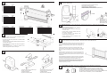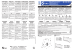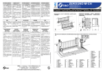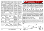
1
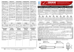
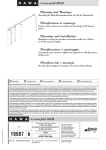
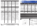
SICUREZZA GENERALE
GENERAL SAFETY
SECURITE GENERALE
ALLGEMEINE SICHERHEIT
SEGURIDAD GENERAL
• L’automatismo SMART è conforme
ai requisiti imposti dalle direttive
2006/95/CEE (bassa tensione)
e 2004/108/CEE (compatibilità
elettromagnetica).
• I collegamenti elettrici devono
essere effettuati nel rispetto delle
disposizioni legislative vigenti.
• L’installatore deve istruire
l’utilizzatore sul corretto
funzionamento dell’automatismo,
sulla manovra manuale
d’emergenza e sui possibili rischi
durante il funzionamento.
• Prima di effettuare qualsiasi
intervento sull’impianto togliere
l’alimentazione elettrica.
• The SMART automatism conforms
to the requirements laid down
by the EEC directives 2006/95
(low voltage) and 2004/108
(electromagnetic compatibility).
• All electrical connections must be
done in compliance with current
laws.
• The installer must instruct the user
on how to use the automatism
correctly, on the manual emergency
manoeuvre and on the possible
risks during operation.
• Always disconnect the electricity
before attempting any work on the
system.
• L’automatisme SMART est conforme
aux prescriptions des directives
2006/95/CEE (basse tension)
et 2004/108/CEE(compatibilité
électromagnétique).
• Les branchements électriques
doivent être conformes à la
législation en vigueur en la matière.
• L’installateur doit informer
l’utilisateur sur le fonctionnement
de l’automatisme, sur la manœuvre
manuelle d’arrêt d’urgence et sur
les risques liés au fonctionnement.
• Coupez l’arrivée de courant
électrique avant toute intervention
sur l’automatisme.
• Der Automatismus SMART entspricht den
Vorgaben der Richtlinien 2006/95/EWG
(Niederspannung) und 2004/108/EWG
(elektromagnetische Verträglichkeit).
• Beim Anschluss an die Stromversorgung
sind die geltenden Gesetze zu befolgen.
• Der Installateur hat den Anwender
bezüglich des korrekten Betriebs des
Automatismus, der manuellen Bedienung
bei Störungen und Notfällen sowie
bezüglich der möglichen Gefahren während
des Betriebs zu unterrichten.
• Vor jeglichen Eingriffen an der Anlage ist
die Stromversorgung zu unterbrechen.
• El automatismo SMART cumple
los requisitos impuestos por las
directivas 2006/95/CEE (baja tensión)
y 2004/108/CEE (compatibilidad
electromagnética).
• Las conexiones eléctricas deben
efectuarse cumpliendo las
disposiciones de ley vigentes.
• El instalador debe instruir al usuario
sobre el funcionamiento correcto
del automatismo, maniobra manual
de emergencia y posibles riesgos
durante el funcionamiento.
• Antes de cualquier operación en la
instalación, cortar la alimentación
eléctrica.
USO
USE
UTILISATION
BETRIEB
USO
SMART-400
INTRODUZIONE
Il libretto di INSTALLAZIONE USO
E MANUTENZIONE è destinato agli
installatori, agli utilizzatori ed agli
operatori della manutenzione.
Leggere attentamente il libretto prima
di installare il prodotto, utilizzarlo e prima
di eseguire manutenzione ordinaria o
straordinaria.
Le operazioni che, se non effettuate
correttamente, possono presentare
rischi, sono indicate con i simboli:
ENTRETIEN
ORDINAIRE
ORDENTLICHE
WARTUNG
MANTENIMIENTO
ORDINARIO
(OGNI SEI MESI)
(EVERY 6 MONTHS)
(TOUS LES 6 MOIS)
(ALLE 6 MONATE)
(CADA 6 MESES)
• La manutenzione deve essere
eseguita solo da personale
qualificato.
• Controllare l’allineamento cancellomotoriduttore e la distanza (1-2 mm)
tra gola del pignone e cresta della
cremagliera.
• Pulire le guide di scorrimento delle
ruote del cancello, ingrassare
leggeremente il pignone del motoriduttore e la cremagliera.
• Verificare manualmente che lo
scorrimento del cancello sia regolare e privo di attriti.
• Controllare la stabilità dei
finecorsa meccanici applicati
sulla guida a terra.
• Controllare il corretto funzionamento della centralina, e dei dispositivi
di sicurezza.
• Controllare che la forza del motore,
in fase di chiusura, non superi i limiti indicati nelle normative vigenti.
• Controllare visivamente che il
cancello, le staffe di fissaggio e la
struttura esistente siano in buone
condizioni.
• Maintenance must be carried out
by qualified personnel only.
• Check alignment of the gate/gear
reducer and the distance (1-2 mm)
between the grooved pinion and the
crest of the rack.
• Clean the guides along which the
gate runs, lightly grease the gear
reducer’s pinion and the rack.
• Manually check that the gate runs
along the guides smoothly without
any friction.
• Check the stability of the
mechanical stops applied on
the ground guide.
• Check that the control unit and
safety devices are all in proper
working order.
• Visually check that the gate, fixing
brackets and existing structure are
in good condition.
• Check that motor force in the closing
phase does not exceed the limits
indicated in the current standards.
• L’entretien doit être effectué
seulement par un personnel
qualifié.
• Contrôler l’alignement porte motoréducteur et la distance (1-2
mm) entre gorge du pignon et crête
de la crémaillère.
• Nettoyer les guides de déplacement des roues de la porte,
graisser légèrement le pignon du
motoréducteur et la crémaillère.
• S’assurer manuellement que le déplacement de la porte est régulier
et s’effectue sans frottement.
• Contrôlez la stabilité des butées
mécaniques de fin de course
appliquées sur le guide au sol.
• Contrôler le fonctionnement de
la centrale et des dispositifs de
sécurité.
• Contrôlez si la force du moteur, en
phase de fermeture, ne dépasse
pas les limites prévues par la
législation en vigueur.
• Visually check that the gate, fixing • S’assurer visuellement que la
brackets and existing structure are porte, les brides de fixation et la
structure existante sont en bon
in good condition.
état.
• Die Wartung hat ausschließlich
durchFachpersonal zu erfolgen.
• Die Fluchtung Tor-Getriebemotor
und den Abstand (1-2 mm)
zwischen Ritzelkehle und
Zahnstangenspitze überprüfen.
• Die Führungsschienen der Torräder
reinigen und den Getriebemotorritzel und die Zahnstange leicht
schmieren.
• Von Hand überprüfen, dass das Tor
korrekt und ohne Reibung auf den
Führungsschienen gleitet.
• Die Stabilität der an den
Bodenführungsschienen
angebrachten mechanischen
Endanschläge überprüfen.
• Die Funktionstüchtigkeit der Steuereinheit und der Sicherheitsvorrichtungen überprüfen.
• Kontrollieren, dass die Motorkraft
während des Schliessvorgangs
nicht die von den geltenden Gesetzen vorgeschriebenen Grenzwerte
überschreitet.
• Per Sichtkontrolle überprüfen, dass
das Tor, die Verankerungsbügel und
die vorhandene Struktur in gutem
Zustand sind.
• El mantenimiento debe ser efectuado
sólo por personal cualificado.
• Comprobar la alineación entre la
cancela y el motorreductor y la
distancia (1-2 mm) entre el canal del
piñón y la cresta de la cremallera.
• Limpiar las guías de deslizamiento de
las ruedas de la cancela, engrasar
ligeramente el piñón del motorreductor y la cremallera.
• Comprobar manualmente que la
cancela se deslice libremente y sin
rozamientos.
• Comprobar la estabilidad de los
finales de carrera mecánicos
aplicados en la guía en el suelo.
• Comprobar que la centralita y los
dispositivos de seguridad funcionen
correctamente.
• Comprobar que la fuerza del motor, en
fase de cierre, no supere los límites
de las normas vigentes.
• Comprobar visualmente que la
cancela, las bridas de sujeción y la
estructura existente estén en buen
estado.
FOLGORAZIONE SCHIACCIAMENTO
La O&O s.r.l. non è responsabile per
danni arrecati a persone, animali o cose
dovuti ad applicazioni che superano
i limiti indicati nella scheda tecnica
allegata o dall’uso diverso da quello per
cui il prodotto è stato progettato.
INTRODUCTION
The INSTALLATION, USE AND
MAINTENANCE handbook is for
installers, users and maintenance
engineers.
Please read it carefully before
installing the appliance, before using
it and before routine or extraordinary
maintenance work.
Operations that, if not carried out
correctly, can be risky, are indicated with
the following symbols:
ELECTROCUTION
CRUSHING
O&O s.r.l. is not liable for injury to
people or animals or damage to things in
the case of applications that exceed the
limits specified on the enclosed technical
data sheet or by a use different from
what the appliance has been designed.
Società soggetta ad attività di direzione e coordinamento di SOMFY S.A.
Company subject to management and coordination activities by SOMFY S.A.
ELECTROCUTION
Das INSTALLATIONS-, BETRIEBSUND WARTUNGSHANDBUCH ist
für die Installateure, Anwender und
Wartungsfachmänner bestimmt.
Das Handbuch ist vor der Installation
des Produkts sowie vor der ordentlichen
und außerordentlichen Wartung sorgfältig
zu lesen.
Wenn die durch folgende Symbole
gekennzeichneten Eingriffe nicht korrekt
durchgeführt werden, kann es zu
Gefahrsituationen kommen:
El folleto de INSTALACIÓN, USO
Y MANTENIMIENTO se destina a
instaladores, usuarios y operadores de
mantenimiento.
Leer detenidamente el folleto antes de
instalar el producto, utilizarlo y efectuar el
mantenimiento ordinario o extraordinario.
Las operaciones que, si no son
efectuadas correctamente, pueden
conllevar riesgos, vienen indicadas con
los símbolos:
ECRASEMENT
La société O&O s.r.l. décline toute
responsabilité en cas de dégâts à des
personnes, animaux ou biens provoqués
par des applications
dépassant les
limites prévues dans la fiche technique
jointe ou par un usage différent de celui
pour lequel l’automatisme a été conçu.
ELECTROCUCIÓN APLASTAMIENTO
STROMSCHLAG QUETSCHUNG
Die Firma O&O s.r.l. haftet nicht für Personen-, Tier- oder Sachschäden, die auf eine
unsachgemäße Anwendung des Produkts
sowie auf das Überschreiten der im technischen Blatt angegebenen Grenzwerte
zurückzuführen sind.
La O&O s.r.l. no es responsable de
daños causados a personas, animales o
cosas, debidos a aplicaciones que superen
los límites indicados en la ficha técnica
adjunta o debidos a utilización diferente
de aquella apra la cual el producto fue
proyectado.
GENERALITA’
GENERAL
GENERALITES
ALLGEMEINES
GENERALIDAD
Il motoriduttore SMART-400 a 24Vdc è
stato progettato per automatizzare cancelli
scorrevoli fino a 400 kg di peso nel rispetto
delle normative europee. E’adatto ad un
utilizzo di tipo residenziale.
The SMART-400 gear reducer 24Vdc
is designed to automate sliding gates
weighing up to 400 kg in compliance with
European standards. It is suitable for use
in residential areas.
Le motoréducteur SMART-400 24Vdc
a été conçu pour l’automation de portes
coulissantes de 400 kg maximum dans le
respect des normes européennes. Il est
adapté à une utilisation de type résidentiel.
Der Getriebemotor SMART -400 24Vdc
wurde für die Automation von Schiebetoren
mit einem Gewicht bis zu 400 kg entwickelt,
erfüllt die EU-Normen und ist für den Einsatz
in Wohnanlagen geeignet.
El motorreductor SMART-400 24Vcc ha
sido específicamente pensado para mover
cancelas correderas de hasta 400 kg de peso,
en el respeto de las normativas europeas. Es
apto para un uso de tipo residencial.
SCHEDA TECNICA - TECHNICAL DATA SHEET - FICHE TECHNIQUE - TECHNISCHES BLATT - FICHA TÉCNICA
230Vac ± 10% 50/60 Hz
MOTORE • MOTOR • MOTEUR • MOTOR • MOTOR
24Vdc
POTENZA ASSORBITA • ABSORBED POWER • PUISSANCE ABSORBÉE • LEISTUNGSAUFNAHME • POTENCIA ABSORBIDA
70W
VELOCITA • SPEED • VITESSE • GESCHWINDIGKEIT • VELOCIDAD
12 m/min
COPPIA • TORQUE • COUPLE • DREHMOMENT • PAR
20Nm
PESO MAX ANTA • MAX LEAF WEIGHT • POIDS MAXI VANTAIL • MAX GEWITCH TORFLÜGEL • PESO MÁX HOJA
400 kg
CENTRALINA • CONTROL UNIT • CENTRALE • STEUEREINHEIT• CENTRALITA
LOG-SB
SICUREZZA ALL’URTO • IMPACT SAFETY • SECURITE AU CHOC • STOSSSICHERHEIT • SEGURIDAD AL CHOQUE
ENCODER
CONDIZIONI AMBIENTALI • ENVIRONMENTAL CONDITIONS • CONDITIONS AMBIANTES • UMGEBUNGSBEDINGUNGEN • CONDICIONES AMBIENTALES
-15 +40 °C
GRADO DI PROTEZIONE • PROTECTION LEVEL • INDICE DE PROTECTION • SCHUTZGRAD • GRADO DE PROTECCIÓN
1
DIMENSIONI D’INGOMBRO • OVERALL DIMENSIONS •
DIMENSIONS HORS-TOUT • ABMESSUNGEN •
MEDIDAS
300
O&O s.r.l. - Via Europa, 2 - 42015 CORREGGIO (R.E.) Italy
tel. +39 (0)522 740111 - fax +39 (0)522 631290
http://www.oeo.it - email: [email protected]
Cette notice est destinée aux
installateurs, aux utilisateurs et aux
techniciens chargés de l’entretien.
Lisez attentivement cette notice, avant
d’installer l’automatisme, de l’utiliser
et avant de procéder à son entretien
ordinaire ou extraordinaire.
Les opérations présentant des
risques si elles ne sont pas effectuées
correctement sont signalées avec les
symboles :
INTRODUCCIÓN
EINLEITUNG
AVANT-PROPOS
ALIMENTAZIONE • POWER • ALIMENTATION • STROMVERSORGUNG• ALIMENTACIÓN
Cod. 035336 Rev.000 del 25/04/10
ROUTINE
MAINTENANCE
EN FR DE ES
INSTALLAZIONE USO E MANUTENZIONE •
INSTALLATION USE AND MAINTENANCE • POSE, MODE D’EMPLOI ET
ET ENTRETIEN • INSTALLATION, GEBRAUCH UND WARTUNG • INSTALACIÓN USO Y MANTENIMIENTO
• Seguire tassativamente le • It is essential to follow the • Suivez scrupuleusement les • Die in dem beigestellten Blatt • Seguir tajantemente las indicaciones
i n d i c a z i o n i c o n t e n u t e n e l instructions given in the enclosed prescriptions reportées sur la feuille “ALLGEMEINE SICHERHEITSVOR- presentadas en la hoja adjunta
foglio allegato “AVVERTENZE “GENERAL INSTRUCTIONS FOR jointe “REGLES GENERALES DE SCHRIFTEN” enthaltenen Anleitungen “ADVERTENCIAS GENERALES
GENERALI PER LA SICUREZZA”. SAFETY” sheet.
sind strikt zu befolgen.
PARA LA SEGURIDAD”.
SECURITE”.
• In caso di manovra manuale seguire • In the case of a manual manoeuvre, • En cas de manœuvre manuelle, • Beim manuellen Manövrieren sind • En caso de maniobra manual seguir
le indicazioni descritte al punto 7.
follow the indications described in suivez les indications décrites au die unter Punkt 7 beschriebenen las indicaciones del punto 7.
• Consultare il manuale d’installazione point 7.
• Consultar el manual de instalación y
paragraphe 7.
Anleitungen zu beachten.
e uso della centralina LOG-SB.
• Consult the LOG-SB control unit’s • Consulter le manuel d’installation et
uso de la centralita LOG-SB.
• Die Installations und Bedienungsaninstallation and operating manual.
d’utilisation de la centrale LOG-SB. leitungen der Steuereinheit LOG-SB
nachschlagen.
MANUTENZIONE
ORDINARIA
IT
AUTOMAZIONE PER CANCELLI SCORREVOLI 24V
AUTOMATION FOR SLIDING GATES 24V
AUTOMATION POUR PORTES COULISSANTES 24V
AUTOMATION FÜR SCHIEBETORE 24V
AUTOMACIÓN PARA CANCELAS CORREDERAS 24V
325
190
2
IP 24
DISPOSIZIONE • LAYOUT • DISPOSITION • DISPOSITION •
DISPOSICIÓN
• Apertura a DESTRA
• Opening on the RIGHT
• Ouverture à DROITE
• Öffnen nach RECHTS
• Apertura a la DERECHA
• Apertura a SINISTRA
• Opening on the LEFT
• Ouverture à GAUCHE
• Öffnen nach LINKS
• Apertura a la IZQUIERDA
3
1)
2)
3)
4)
4)
5)
6)
7)
6
NOTA CAVI • CABLE NOTE • CONNEXION CABLE • BEMERKUNG ZU KABEL ANSCHLÜSSEN • NOTA CABLES
Linea Monofase
Fotocellula Trasmettente
Fotocellula Ricevente
Lampeggiante 24V
Antenna
Selettore a chiave
Battuta chiusura
Battuta apertura
MONTARE LA CREMAGLIERA • MOUNT THE RACK • MONTEZ LA CREMAILLERE • MONTAGE DER ZAHNSTANGE
MONTAR LA CREMALLERA
•
•
•
•
•
2 x 1,5 + T
2 x 0,5
4 x 0,5
2 x 0,5
RG58 (4m)
3 x 0,5
2 x 0,5
2 x 0,5
Accoppiamento pignone-cremagliera (modulo 4)
Rack-to-pinion coupling (module 4)
Assemblage pignon-crémalière (module 4)
Zwischen Zahnstange und dem Antriebsritzel (Ritzelmodul 4)
Acoplamento piñon-cremaliera (módulo 4)
7
1
3
1 ÷ 2 mm
6
1)
2)
3)
4)
4)
5)
6)
7)
Single-phase line
Transmitter photocell
Receiver photocell
Flashing light 24V
Antenna
Key selector
Closing sensitive edge
Opening sensitive edge
2 x 1,5 + T
2 x 0,5
4 x 0,5
2 x 0,5
RG58 (4m)
3 x 0,5
2 x 0,5
2 x 0,5
4
76
2
5
100
7
1)
2)
3)
4)
4)
5)
6)
7)
Ligne monophasée
Photocellule émettrice
Photocellule réceptrice
Clignotant 24V
Antenne
Sélecteur à clé
Capteur fermeture
Capteur ouverture
4
2 x 1,5 + T
2 x 0,5
4 x 0,5
2 x 0,5
RG58 (4m)
3 x 0,5
2 x 0,5
2 x 0,5
•
•
•
•
•
25
1)
2)
3)
4)
4)
5)
6)
7)
Einphasenleitung
Senderfotozelle
Empfängerfotozelle
Blinkleuchte 24V
Antenne
Schlüsselschalter
Anschlag beim Schließen
Anschlag beim Öffnen
2 x 1,5 + T
2 x 0,5
4 x 0,5
2 x 0,5
RG58 (4m)
3 x 0,5
2 x 0,5
2 x 0,5
1)
2)
3)
4)
4)
5)
6)
7)
Línea monofásica
Fotocélula transmisor
Fotocélula receptor
Indicador intermitente 24V
Antena
Selector de llave
Disp. sensible a la presión
Tope de abertura
BASAMENTO • BASE • BASE • BASIS • BASE
MANOVRA MANUALE • MANUAL MANOEUVRE • MANOEUVRE MANUELLE • MANUELLES MANÖVRIEREN
MANIOBRA MANUAL
• Prima di effettuare qualsiasi intervento sull’impianto
togliere l’alimentazione elettrica.
• Always disconnect the electricity before attempting any
work on the system.
• Coupez l’arrivée de courant électrique avant toute
intervention sur l’automatisme.
• Vor jeglichen Eingriffen an der Anlage ist die
Stromversorgung zu unterbrechen.
14
• Antes de cualquier operación en la instalación, cortar
la alimentación eléctrica.
• Fissare la piastra di base con tasselli ad espansione oppure
annegare le zanche nel calcestruzzo.
• Secure the base plate with expansion bolts or embed the fishtail
clamps in concrete.
2 x 1,5 + T
2 x 0,5
4 x 0,5
2 x 0,5
RG58 (4m)
3 x 0,5
2 x 0,5
2 x 0,5
160
75
330
25
Allineamento cremagliera
Rack alignment
Alignement crémaillère
Fluchtung der Zahnstange
Alineación de la cremallera
76
8
90°
MONTAGGIO ARRESTI MECCANICI • INSTALL MECHANICAL STOPS ASSEMBLY • MONTAGE DES BUTÉES MÉCANIQUES •
MONTAGE DER MECHANISCHEN SPERREN • MONTAJE DE LOS TOPES MECÁNICOS
• Fixer la plaque de base à l’aide de chevilles à expansion ou enfouir
les agrafes dans le béton.
Installare sulla guida di scorrimento a terra gli arresti meccanici di finecorsa
opportunamente dimensionati alla massa del cancello. Gli arresti meccanici servono come riferimento di finecorsa per le manovre di apertura e di
chiusura.
• Die Grundplatte mit Dübeln befestigen oder die Verankerungsklauen
in Beton eingießen.
• Fijar la placa de fundación con tornillos de expansión o bien
introducir las grapas de anclaje en el hormigón.
5
Install the mechanical end of travel stops on the sliding guides on the
ground. Their size must be suitable for the gate’s weight. The mechanical
stops act as an end of travel reference for the opening and closing manoeuvres.
MONTAGGIO • ASSEMBLY • MONTAGE • MONTAGE • MONTAJE
Installez les butées mécaniques de fin de course correctement dimensionnées en fonction du poids de la porte sur le guide de coulissement au sol.
Les butées mécaniques servent de point de fin de course pour l’ouverture
et la fermeture.
An den Bodenführungsschienen die für das Gewicht des Tors geeigneten
mechanischen Endanschlagsperren installieren. Die mechanischen Sperren dienen als Endanschlag beim Öffnen und Schließen des Tors.
Instalar en la guía de deslizamiento en el suelo los topes mecánicos de
final de carrera oportunamente dimensionados para la masa de la cancela.
Los topes mecánicos sirven de referencia de final de carrera para las
maniobras de apertura y de cierre.
9
•
•
•
•
•
Regolazione orizzontale e fissaggio
Horizontal adjustement unit and anchorage
Réglage orizontal et fixation
Horizontale Einstellung
Regulación horizontal y fijación
•
•
•
•
•
Regolazione verticale o messa in bolla
Vertical adjustement and unit leveling
Réglage vertical ou mise à niveau
Vertikale Einstellung
Regulación vertical y nivelación
COLLEGAMENTI ELETTRICI • ELECTRICAL CONNECTIONS • BRANCHEMENTS ELECTRIQUES •
ELEKTRISCHE ANSCHLÜSSE • CONEXIONES ELÉCTRICAS
• Consultare il manuale d’installazione e uso della centralina LOG-SB
• Consult the LOG-SB control unit’s installation and operating manual
• Consulter le manuel d’installation et d’utilisation de la centrale LOG-SB
• Die Installations und Bedienungsanleitungen der Steuereinheit LOG-SB nachschlagen.
• Consultar el manual de instalación y uso de la centralita LOG-SB